Article

A New Strengthening Process for Carbon-Fiber-Reinforced Thermoplastic Polyphenylene Sulfide (CFRTP-PPS) Interlayered Composite by Electron Beam Irradiation to PPS Prior to Lamination Assembly and Hot Press

1
Graduate School of Engineering, Tokai University, Hiratsuka 259-1292, Japan
2
Graduate School of Science & Technology, Tokai University, Hiratsuka 259-1292, Japan
3
Faculty of Liberal Arts and Science, Tokyo City University, Yokohama 224-8551, Japan
4
Kanagawa Institute of Industrial Science and Technology (KISTEC), Ebina 243-0435, Japan
5
Laboratory of Tribology and Dynamics of Systems (LTDS), Ecole Centrale de Lyon, 69134 Ecully, CEDEX, France
*
Author to whom correspondence should be addressed.
Materials 2023, 16(7), 2823; https://doi.org/10.3390/ma16072823
Submission received: 30 January 2023 / Revised: 18 March 2023 / Accepted: 30 March 2023 / Published: 1 April 2023
(This article belongs to the Special Issue Future Perspectives on Carbon Fibers and Their Composites)

Abstract

:
Impact by hailstone, volcanic rock, bird strike, or also dropping tools can cause damage to aircraft materials. For maximum safety, the goal is to increase Charpy impact strength (auc) of a carbon-fiber-reinforced thermoplastic polyphenylene sulfide polymer (CFRTP-PPS) composite for potential application to commercial aircraft parts. The layup was three cross-weave CF plies alternating between four PPS plies, [PPS-CF-PPS-CF-PPS-CF-PPS], designated [PPS]4[CF]3. To strengthen, a new process for CFRP-PPS was employed applying homogeneous low voltage electron beam irradiation (HLEBI) to both sides of PPS plies prior to lamination assembly with untreated CF, followed by hot press under 4.0 MPa at 573 K for 8 min. Experimental results showed a 5 kGy HLEBI dose was at or near optimum, increasing auc at each accumulative probability, Pf. Optical microscopy of 5 kGy sample showed a reduction in main crack width with significantly reduced CF separation and pull-out; while, scanning electron microscopy (SEM) and electron dispersive X-ray (EDS) mapping showed PPS adhering to CF. Electron spin resonance (ESR) of a 5 kGy sample indicated lengthening of PPS chains as evidenced by a reduction in dangling bond peak. It Is assumed that 5 kGy HLEBI creates strong bonds at the interface while strengthening the PPS bulk. A model is proposed to illustrate the possible strengthening mechanism.

1. Introduction

Carbon-fiber-reinforced polymers (CFRPs) have been increasingly utilized for commercial airplanes and space vehicles, among many other articles, due to being lightweight and having a high strength-to-weight ratio. CFs are often used for reinforcement due to their high strength, surface area, and conductivity along with inertness and stability at high temperature. Along with advanced airplane materials, potential applications of CF are: CO2 capture for reducing climate change [1]; battery electrodes applied to EVs [2]; and advancement of utilizations for thermally conductive carbon-reinforced composites [3]. Besides CF [4,5], several types of carbon reinforcements have been used, including: carbon nanotubes [6,7], carbon nanofibers [8], graphite, graphene, carbon black [9], and ultrathin carbon nanotube (CNT) veils to enhance interlaminar toughness [10].
For aerospace, a popular resin of choice has been thermoset (TS) epoxy; however, the CFRPTSs are very difficult to recycle causing serious harm to the environment if disposed of improperly, and have a long solidification time during fabrication, requiring high energy consumption. CFRP thermoplastics (CFRTPs), on the other hand, have been a viable alternative since they reduce waste by being able to be repeatedly formed and remelted, allowing recyclability to contribute to environmental sustainability.
TP resins have been increasingly used for commercial airplane parts [9,11,12], one of which is polyphenylene sulfide (PPS) with formula (C6H4S)n as shown in Figure 1a. CFRTP-PPS is widely used and has application value for articles such as: ailerons, leading edge access panels, keel beam main ribs in the A340-500/600, landing flap rib in the Dornier 328, and the main landing gear door of the Fokker 50. PPS resin continues to gain attention as one of the “High Performance TPs”, similar to polyetheretherketone (PEEK) and polyetherketoneketone (PEKK) [11], that has increased rigidity due to aromatic rings inhibiting excessive backbone chain movement and increased intermolecular forces giving it strength. In PPS, sulfur (S) groups connect aromatic groups, allowing flexibility [11,13]. PPS is a widely utilized semicrystalline engineering TP polymer [9] with many advantages such as superior toughness, high modulus, tensile strength, and creep as well as excellent dimensional and high temperature stability, inherent flame resistance, and good electrical properties [4,14]. It is resistant to harsh environments [4,15] such as gasoline, oil, road salt, and exhaust gasses in high-temperature environments that airplane parts can encounter [4]. Crystallinity of PPS can reach ~60% contributing to its strength [9]. PPS has a glass transition temperature (Tg) of 358 K (85 °C) and high melting temperature (Tm) of ~558 K (~285 °C) [14], and can withstand higher temperatures of ~473 K (~200 °C) [11]. PPS has been used for large-scale CFRTP-PPS parts such as 3D-printed composite articles [16]; including, that of continuous CF with nominal Vf of 30 to 50%, reaching ultimate tensile strength of 1930 +/− 150 MPa [17]. CFRTP-PPS is well-researched, with recent studies that include: effect of cooling rate on elastic modulus and ultimate tensile strength [18]; heat treatment process to remove CF fabric sizing on laminates showing that Charpy impact strength was more dependent on CF volume fraction [19]; and an inventory analysis on CFRTP-PPS manufacture in the aerospace industry, exemplifying the urgent need to lower environmental impact [20].
But CFRTPs have some disadvantages, such as: (1) high processing temperature with high TP melt viscosity of 200 to 600 Pas, making flow into intricate spaces between CFs difficult [23]; and (2) TP does not adhere well to CF from their inert surfaces. Therefore, two aims of this study are: (1) to construct the laminated structure [PPS-CF-PPS-CF-PPS-CF-PPS] with alternating PPS and CF plies to minimize required melt flow distance of PPS through CF ply thickness (~230 µm) during hot press; and (2) to overcome the latter, we activate PPS plies with low voltage 100 keV-class homogeneous electron beam irradiation (HLEBI) prior to lamination assembly and hot press.
To give a background, CFRTPs are generally weaker than CFRPTSs, mostly from poor adhesion at the CF/TP polymer interface in the form of sparse point contacts distributed heterogeneously along the CF surface [24]. As a result, treating the CF surface to strengthen the CF/TP interface has been a focus of a wide body of research, including: introduction of functional groups to the CF for increased chemical bonding [25]; electrochemical and plasma treatments [26]; electrochemical oxidation [27]; and acidic functional groups [28]. Various methods have been used to strengthen the CF/PPS interface in CFRTP-PPS composites [4,5]. In CFRTP-PPS injection-molded composites, addition of 5 wt% animated polyphenylene sulfide (PPS-NH2) with weight ratio (CF:PPS:PPS-NH2 = 20:75:5) has been found to increase tensile, flexural strength, and flexural modulus 11.4, 11.0, and 22.7%, respectively, over that without PPS-NH2 [4]. This was attributed to higher adhesion from the -NH2 groups bonding with epoxy, -C-OH, and -C-O-C- groups in the CF sizing [4]. In another study, addition of the sizing agent component carboxylic polyphenylene sulfide (PPS-COOH) to the CF surface increased interfacial shear strength of CFRTP-PPS 27 and 15% higher than untreated and plasma treated, respectively [5]. Chen, Mohanty and Misra (2021) provide a comprehensive review of carbon reinforcements in PPS composites [9].
It follows that HLEBI is an increasingly used surface treatment that does not require chemicals and can be applied to large sheets. Applying HLEBI to sample surfaces has been shown to improve fracture toughness of several CF and glass fiber (GF) FRPs [29,30,31,32,33,34,35]. Moreover, HLEBI has been utilized to directly activate CF [24,36,37,38,39,40,41] and GF [42] to increase mechanical properties of FRP. HLEBI is reported to strengthen glasses [43,44] and BMCs [33] by generating dangling bonds at low bond dissociation energy (BDE) sites with repulsive force between electrons, creating internal compressive forces. In CF [28] and PPS, HLEBI decreases dangling bond density, probably due to 6-membered rings of conjugated carbon atoms. However, a novelty of this study is that we use HLEBI to treat the matrix of PPS, not the CFs. Figure 1b shows sites in PPS where BDE of aromatic-S (AR-S) bond is much lower (~285 kJmol−1) than AR-H at 461 kJmol−1 [14]. Since monomers are connected by sulfide (-S-) groups, reducing AR-S dangling bonds would assumably lengthen PPS chains, strengthening the PPS structure. Moreover, charge transfer would occur from the activated PPS to the CFs, enhancing adhesion at the CF/PPS interface and strengthening the interlayered [PPS]4[CF]3 composite.
Up to now, there has been few studies of HLEBI to strengthen CFRTP-PPS composites. One study was found applying 32 to 90 kGy HLEBI to CFRTP-PPS; however, data appear inconclusive due to few data points [45]. Therefore, the goal of this study is to demonstrate that, for a [PPS]4[CF]3 interlayered composite of three CF plies alternated between four PPS plies [PPS-CF-PPS-CF-PPS-CF-PPS], the new process of applying HLEBI to PPS plies prior to lamination assembly with untreated CF plies and hot press can increase the important mechanical property of impact strength for potential application to airplane parts. A model is proposed to explain the strengthening mechanism by HLEBI in PPS plies themselves, and the CF/PPS interface.

2. Experimental Procedure

2.1. Preparation of Sized CF and PPS

Plain cross-weave CF (TR3110M) plies from Mitsubishi Rayon Ltd., Tokyo, Japan were used with listed areal weight of 198 to 200 gm−2, and nominal thickness of 230 µm [46]. The CFs were provided with typical epoxy film sizing coating with nano-thickness and whose composition was determined by proton-NMR (AVANCE500, Neutron Magnetic Resonance, Shimazu, Kyoto) [47]. Branched type PPS was used (B-063S, TOSO Co. Ltd., Tokyo, Japan) that has been utilized for automobile parts such as gears, fuel, and other fluid transport tubes and ducts, along with electrical systems. Branched type PPS was chosen because it is reported to have higher molecular weight (M.W.) and better mechanical properties such as higher ductility than that of normal PPS which has a M.W. of ~18,000 [14]. Specific mechanical and other properties of the provided PPS are not listed and are proprietary.

2.2. Composite Fabrication

CFRTP-PPS composite fabrication consisted of four basic steps as shown in Figure 2:
Step 1: HLEBI was applied homogeneously to both side surfaces of PPS sheets (see the next section). Step 1 is eliminated for untreated samples.
Step 2: Laminate assembly was carried out with 3 plies of sized untreated CF placed alternately between 4 plies of PPS to obtain a lay-up of [PPS-CF-PPS-CF-PPS-CF-PPS], designated here as [PPS]4[CF]3.
Step 3: Samples were then cured by one-directional hot press (IMC-185A, Imoto Machinery Co., Ltd., Tokyo, Japan) at 4.0 MPa and 573 K for 8 min.
Step 4: Samples were cut to size: length, width, and thickness of 80 × 10 × 1.5 mm.
The HLEBI samples were compared to a control without HLEBI (eliminating Step 1). Volume fraction, Vf of CFs in the laminate samples was 0.55 (55%). Nine samples each were tested for each data set of: untreated, 5, 10, 20, and 30 kGy HLEBI conditions.

2.3. Conditions of HLEBI

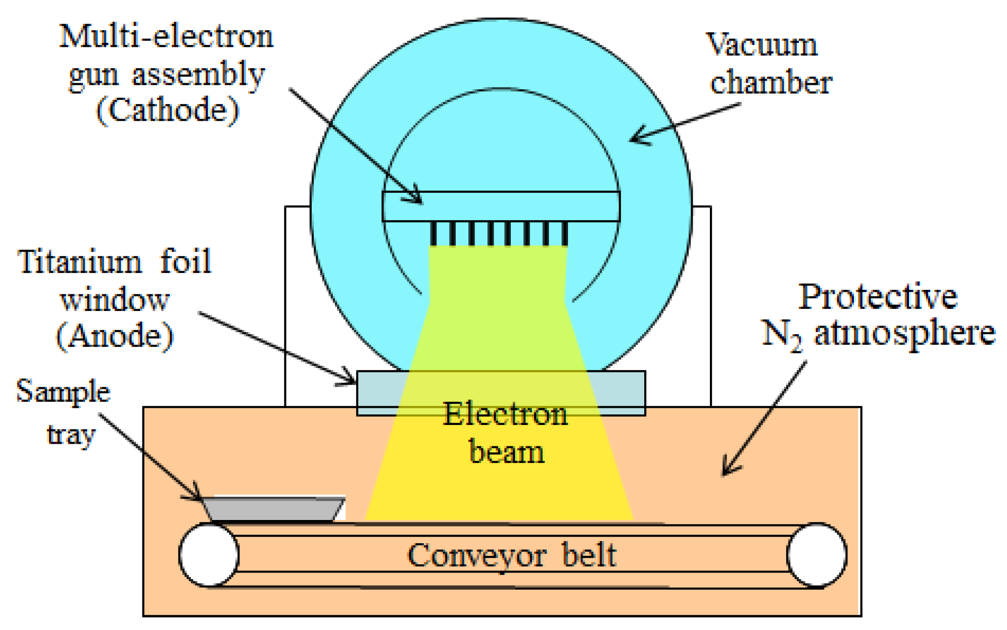
PPS plies were treated by HLEBI on both sides by an electron–curtain processor (Type CB175/15/180L, Energy Science Inc., Woburn, MA, USA, Iwasaki Electric Group Co., Ltd., Tokyo, Japan) prior to lamination assembly with untreated sized CFs. Acceleration voltage, and distance between sample and Ti thin film window were 170 kV and 25 mm, respectively. Figure 3 shows a schematic of the electron curtain processor. HLEBI setup and parameters are described in detail in [38].
Based on the density of PPS (1350 kgm−3) [48], electron beam penetration depth, Dth, is calculated to be 164 μm [49]. Within Dth, dangling bonds (Figure 1b) are reported to be formed [29,33,42] or reduced [29,36,37] depending on the material treated. During lamination assembly and hot press, charge transfer should occur from PPS into the highly conductive CF. Note HLEBI was applied to PPS plies only, not CF plies.

2.4. Charpy Impact Test

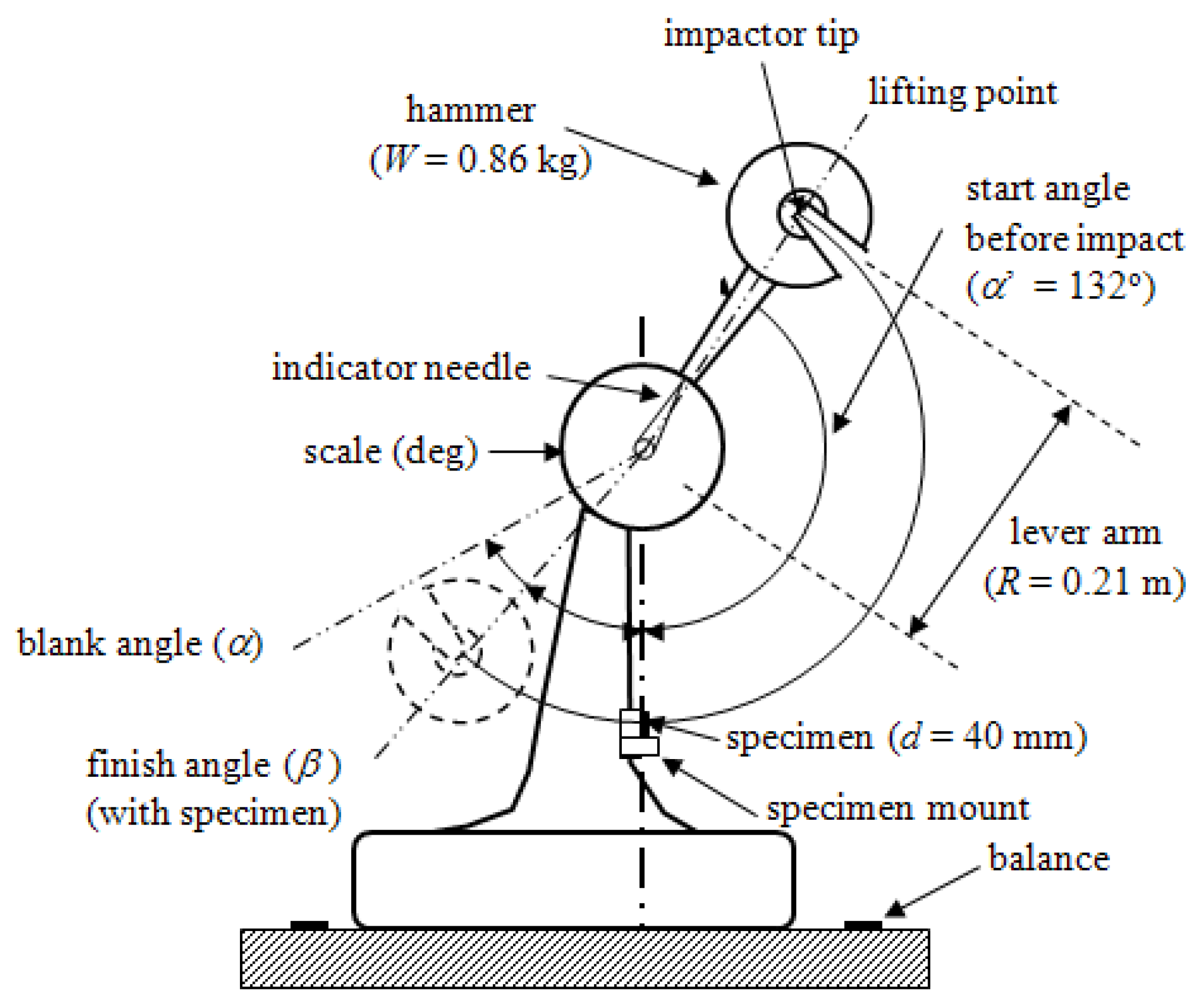
The Charpy impact test is typically used to give a rough or better estimation to screen candidate airplane materials for further testing such as impact drop tower, compression after impact (CAI), edge delamination strength (EDS), and tensile, to name a few. Charpy impact tests were carried out using a standard impact fracture energy measurement system (Shimadzu Corporation No.51735) in accordance with Japanese Industrial Standard, (JIS K 7077) [20,36,50]. Figure 4 illustrates a schematic. Impact fracture energy, E (kJ) is calculated by Equation (1) [32,50]:
E = WR[(cosβ-cosα) − (cosα′-cosα)][(α + β)/(α-α′)]
Here, E, W, R, β, α, and α′ are: impact fracture energy (kJ); hammer mass (kg); length (m) of hammer weight point from rolling center; maximum angle after impact (Radians); start angle before impact (a = 2.3 Radians or 132°); and maximum angle of blank test, respectively. Angles are read by mechanical indicator needle in Figure 4.
Three blank tests are conducted to calibrate the impactor for environmental conditions such as atmospheric pressure, temperature, and humidity. Charpy impact strength (kJ m−2) is calculated by Equation (2):
auc = E/(bt)
Here, E, b (=10 ± 0.2 mm) and t (=1.5 ± 0.15 mm) are: impact fracture energy (J), sample width (mm), and thickness (mm). The distance d between supporting points in the specimen holder was 40 mm.

2.5. Accumulative Probability

Accumulative probability (Pf) is a statistical calculation to rank samples from weakest to strongest, assigning numeric strength between 0.0 and 1.0. Pf is calculated in Equation (3) based on the median rank method [52]:
Pf = (i − 0.3)/(Ns + 0.4)
Here, Ns and i are the total number of samples (9) and rank order integer of Charpy impact strength of each sample (1 to 9). For i of 1, 5, and 9, Pf are 0.07, 0.50, and 0.93, respectively.

2.6. Microscopy and Energy Dispersive Spectroscopy (EDS)

To examine sample surfaces, an optical microscope (12.7: 1 optical zoom ratio, Nikon Model SMZ1270i, Tokyo, Japan) was used, along with a JEOL SEM (Model JCM-6000PLUS, Tokyo, Japan) with EDS to obtain elemental mapping (acceleration voltage 10 kV; irradiation current 7.47500 nA).

2.7. Electron Spin Resonance (ESR) Spectroscopy

To detect dangling bonds in PPS before and after HLEBI, PPS samples were analyzed by an electron spin resonance spectrometer (ESR, JES-FA2000, Nippon Denshi, Ltd., Tokyo, Japan). ESR detects spins of unpaired electrons (ms = +/−1/2) since electrons have spin quantum number and magnetic moment. Magnetic moments of the unpaired electrons align themselves parallel or antiparallel to an applied magnetic field, resulting in output peak at a specific magnetic field, B [33].

3. Results

3.1. Relationship between HLEBI to PPS and Impact Strength of [PPS]4[CF]3 Samples

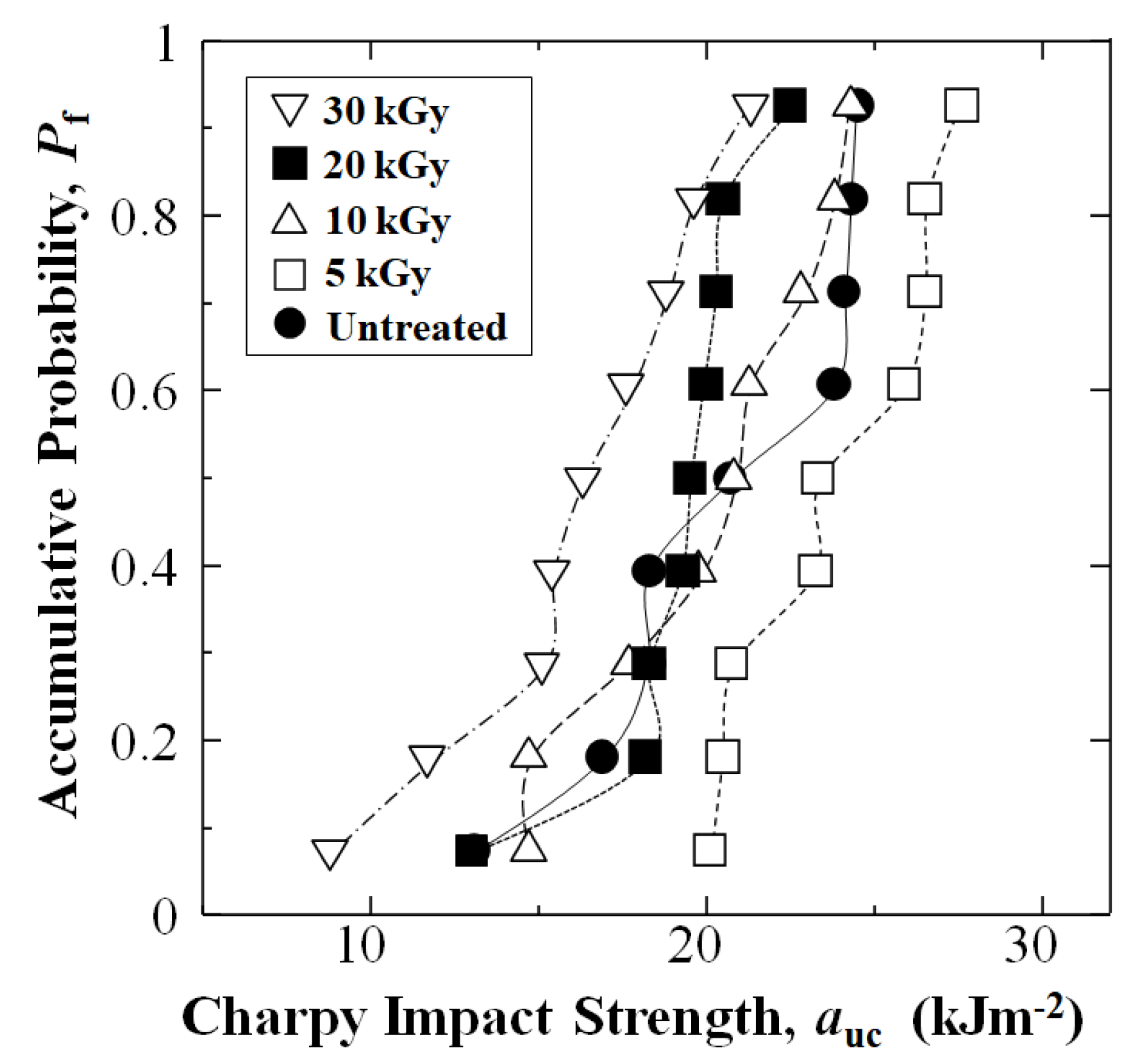
Figure 5 and Table 1 show experimental results of changes in Charpy impact strength (auc) of the CFRTP-PPS [PPS]4[CF]3 composite as a function of accumulative probability (Pf) for data sets of untreated and HLEBI treated of 5, 10, 20, and 30 kGy, respectively. Namely, the small dose of 5 kGy appears to be at or near the optimum for improving impact resistance since it raised auc at each Pf. Importantly, the 5 kGy dose increased auc significantly (53%) for the weakest samples in the datasets (Pf = 0.07) from 13.1 to 20.1 kJ m−2, indicating increased reliability and safety.
However, Figure 5 and Table 1 show that as the HLEBI dose was increased from 10 to 30 kGy the auc was decreased; the 30 kGy resulting in the lowest auc due to excess radiation damage.
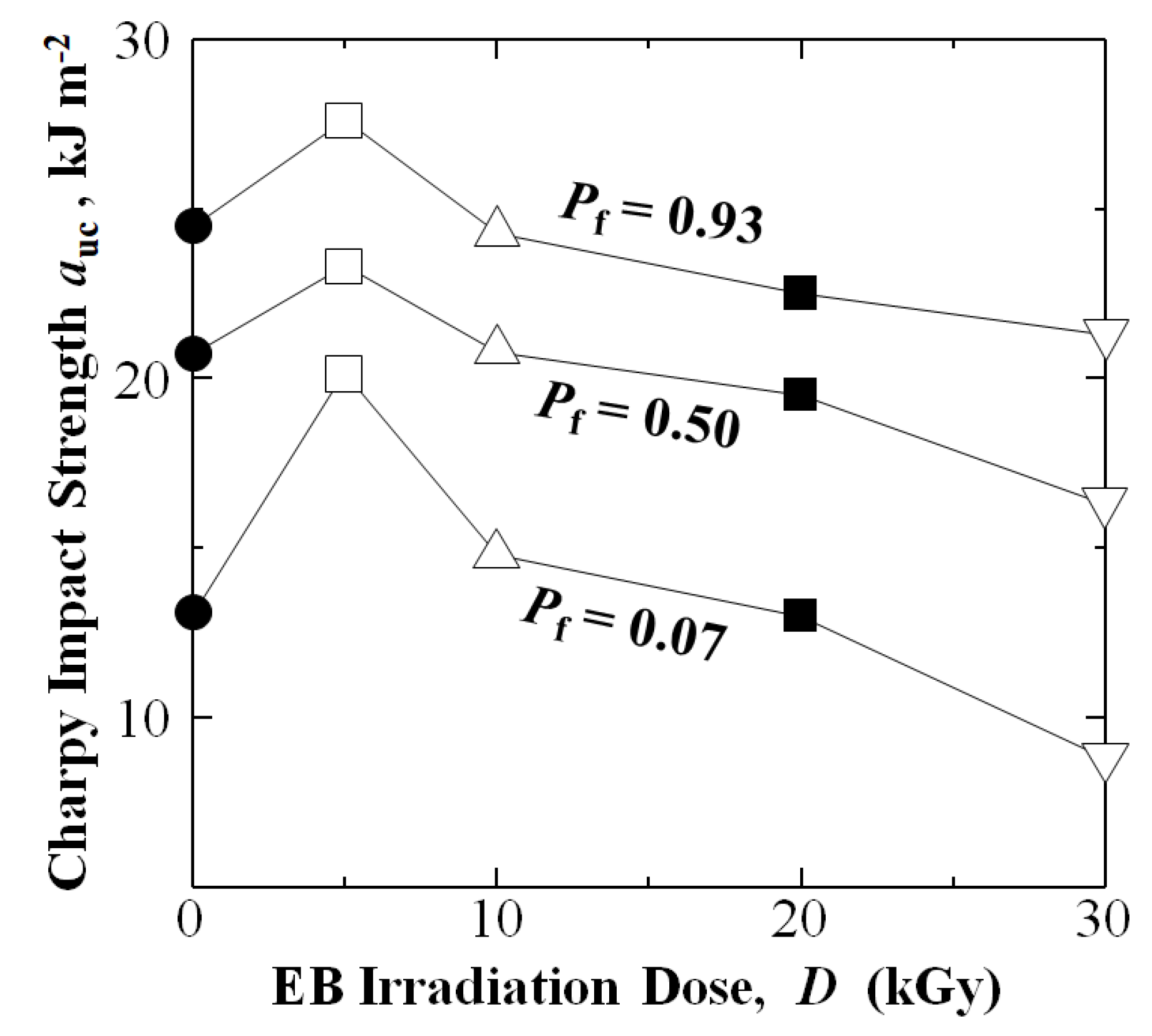
Figure 6 plots auc of [PPS]4[CF]3 for low-, median-, and high-Pf of 0.07, 0.50, and 0.93, respectively, showing auc at maximum at 5 kGy, then decreasing as the dose is increased from 10 to 30 kGy. The 5 kGy HLEBI dose increased auc to 20.1, 23.3, and 27.6 kJ m−2, respectively, which are 53%, 12%, and 13% higher than those untreated samples at 13.1, 20.7, and 24.5 kJ m−2 (Figure 6 and Table 1). In contrast, the 10 kGy dose increased auc slightly at low-Pf of 0.07 from 13.1 to 14.7 kJ m−2; while, resulting in slight to no change compared to untreated samples at Pf = 0.50 from 20.7 to 20.8 kJ m−2 and at Pf = 0.93 from 24.5 to 24.3 kJ m−2.
The 20 kGy reduced auc to 13.0, 19.5, and 22.5 kJ m−2; and 30 kGy lowered auc further to 8.9, 16.3, and 21.3 kJ m−2 at Pf of 0.07, 0.50, and 0.93, respectively.

3.2. Determination of Statistically Lowest Impact Strength, as (auc at Pf = 0)

The statistically lowest impact strength, as (auc at Pf = 0), is calculated by the 3-dimensional Weibull calculation [53] for each data set. In industry, for a batch of manufactured products, the as calculation is commonly used to determine the statistically weakest part to estimate safety limits and reliability in quality control (QC).
When the equation is assumed to be applicable to the experimental auc, the Pf depends on risk of fracture [32,53]. The as, coefficient m, and the constant aIII, are key parameters for predicting the required strength for new structural materials,
Pf = 1 − exp[–([aucas]/aIII)m]
with linear form:
ln(−ln(1 − Pf)) = mln(aucas) − mlnaIII
where m is shape parameter, and aIII is scale parameter or characteristic strength [54].
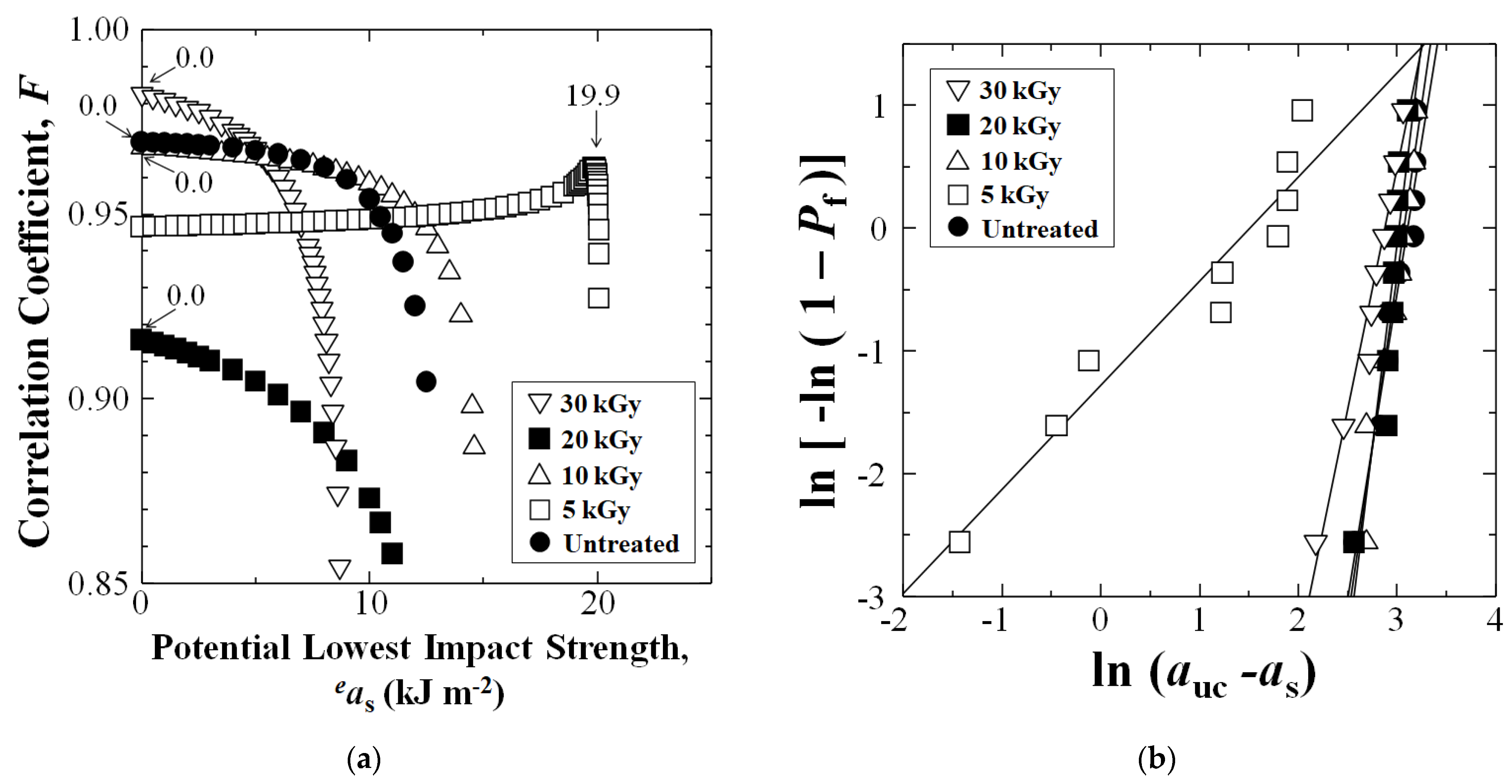
Figure 7a shows when linear form Equation (5) is iterated to the highest correlation coefficient F, the as is obtained. Iteration is done with Microsoft Excel 97-2003 inputting potential lowest impact values eas until F is at a maximum. The 5 kGy HLEBI data set (squares) exhibited the highest as at 19.9 kJ m−2, indicating that the 5 kGy HLEBI increases safety and reliability of [PPS]4[CF]3 samples. Figure 7b shows linear plots between ln (aucas) and ln [−ln(1 − Pf)] whose slopes and y-intercepts are m and − mlnaIII, respectively.
Average auc and standard deviations (in brackets) for untreated, 5, 10, 20, and 30 kGy HLEBI data sets are 20.4 (4.1), 23.8 (2.9), 20.0 (3.6), 19.1 (2.6), and 16.1 (3.9) kJ m−2, respectively. However, the focus here is plotting Pf vs. auc, as shown in Figure 5, since it indicates type of scatter. Standard deviation does not indicate if some specimens have much lower auc than the rest, or if the bulk of scatter is in stronger specimens. Therefore, Figure 5 and Figure 7a clearly show that the 5 kGy HLEBI improved auc at all Pf over untreated; and the as (auc at Pf = 0) of 19.9 kJ m−2 is the maximum over all other data sets, which exhibited as of 0 kJ m−2.

3.3. Optical Microscopy Observation

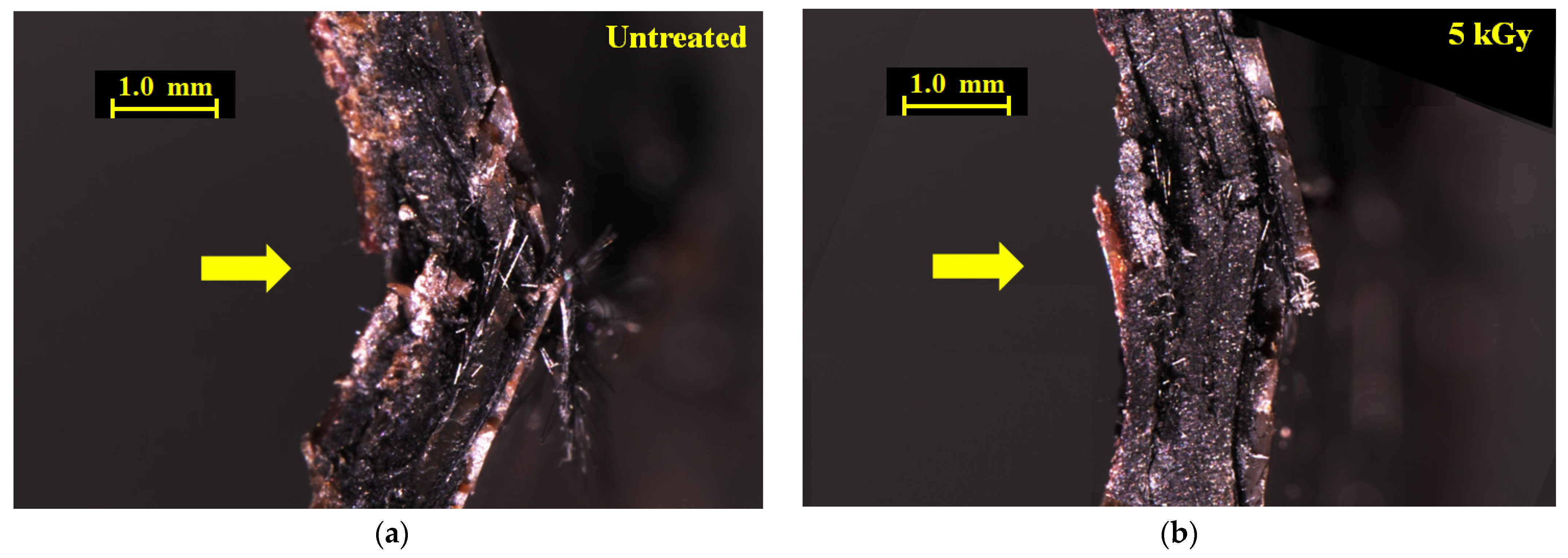
To explain strengthening of the [PPS]4[CF]3 samples by HLEBI, Figure 8a,b show optical microscopy photos of impacted untreated and 5 kGy [PPS]4[CF]3 samples, respectively. Side views are shown, arrows indicating impact direction. Most evident is that plies of the 5 kGy sample maintained cohesion within the interlayered structure with little or no CF separation or pullout compared with untreated samples. The 5 kGy sample is bent to a much lower degree, indicating increased rigidity in the interlayered system. On the other hand, the untreated sample shows ply separation with CFs protruding out from the tensile surface of the impact zone, and a high degree of damage within its interlayered structure.
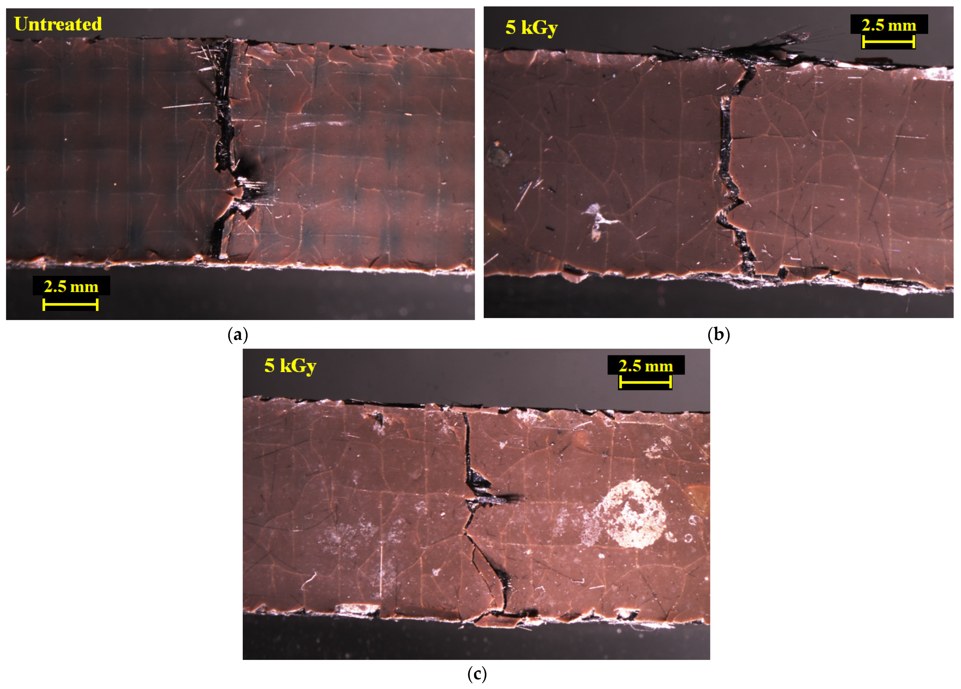
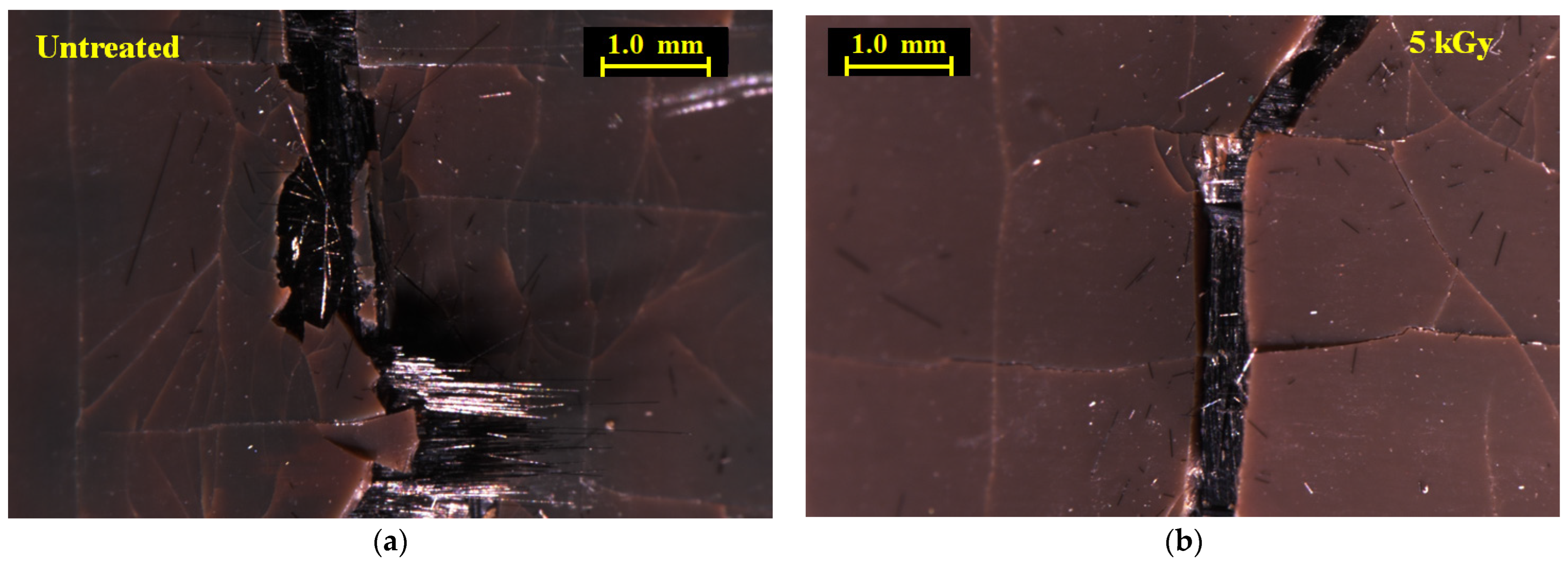
Figure 9a–c show photos of the tensile side surface for untreated and two 5 kGy samples. Notably, Figure 9 shows that the main cracks across the outer PPS ply of the 5 kGy samples are narrower than those of untreated samples. Here, little or no CFs are seen projecting from the main crack, although some CFs are projecting from the specimen side (top) in Figure 9b. Figure 10a,b show closeups from Figure 9a,b. Most evident is in the 5 kGy sample, where the CF ply under the outer PPS ply exhibits consolidation with no CF separation observed and the CF cross-weave can be clearly seen. In contrast, in untreated sample CF plies, under the main crack are damages with separation and pull-out. The 5 kGy HLEBI apparently prevented the main crack from propagating from the outer PPS ply into the adjoining CF ply. In summary, Figure 8, Figure 9 and Figure 10 indicate increased adhesion at the CF/PPS interface as the 5 kGy HLEBI leads to increased resistance to CF pull-out and improved impact strength.

3.4. SEM and EDS Observation

To explain damage reduction in Figure 8, Figure 9 and Figure 10 by HLEBI, SEM, and EDS, analyses were carried out. Figure 11 shows SEM photomicrographs of untreated (a) and 10 kGy (b) fracture surfaces. Figure 10b shows that HLEBI increases PPS/CF adhesion, as evidenced by PPS adhering to CF at point contacts, although it could not be found in the untreated sample.
Figure 12 shows EDS element mappings for untreated (a), 5 kGy (b), and 10 kGy (c) samples, respectively, where red and green represent oxygen (O) Kα and sulfur (S) Kα and Kβ emissions. Here, S represents PPS resin. The untreated sample shows clean CF surfaces, whereas the 5 kGy apparently shows retention of S (PPS) on the CF extending with the CF shape. In addition, the 10 kGy indicates PPS adhering to and spanning between CFs, along with point contacts on the CFs. Overall, Figure 11 and Figure 12 show that HLEBI can increase PPS/CF adhesion. However, while the 10 kGy dose increases PPS/CF adhesion, it lowers auc below that of 5 kGy by excess radiation damage which is described in the next section.

3.5. Increasing Fiber Pull-Out Resistance and ESR Results

As mentioned earlier, HLEBI is reported to increase fiber pull-out resistance between CF and TPs in CFRTP-PEEK [55], CFRTP-ABS [41], and CFRTP-PC [40]. In short fiber CFRTP-PEEK, SEM observation of fracture surfaces showed that HLEBI increases the area of PEEK adhering to CF, with PEEK spanning between CFs for more consolidated structure [55].
To characterize the strengthening mechanism on the molecular scale, ESR analysis of untreated and HLEBI-treated PPS plies was carried out. This is because ESR has been widely implemented as a tool to characterize reaction mechanisms in polymer systems detecting free radicals during chain growth, or depolymerization reactions [56]. Dangling bonds are free radicals that are typically immobile [56].
Figure 13 shows experimental results of ESR analysis of PPS untreated, along with HLEBI treated at 5, 10, 15, and 20 kGy. Table 2 shows a summary. Based on BDE, intensity change in ESR signals of PPS in Figure 13 can be explained. Three peaks were detected, labelled “1”, 2”, and “3”: Peak 1 being the large peak whose inflection point is at magnetic field B at 320.3 mT. Although ESR peaks cannot generally determine the kind of dangling bonds, B of Peak 1 at 320.3 mT is assumed to represent spontaneous AR-S dangling bonds; while, Peaks 2 and 3 at B = 319.9 and 319.5 mT are assumed to represent AR-H. This is because AR-S has significantly lower BDE of 285 kJ mol−1 compared with AR-H at 461 kJ mol−1 [22]. Note both Peaks 2 and 3 only appear at higher HLEBI treatments of 10 kGy and above, and the Peak 2 is higher intensity than Peak 3.
Figure 13 shows that Peak 1 was reduced by 5 kGy HLEBI, indicating decreasing AR-S dangling bond density. Since ESR detects free radicals, the mechanism is assumed to be chain lengthening to strengthen the PPS matrix. In addition, the heat energy of HLEBI apparently acted to recover the AR-S bonds. Moreover, upon lamination assembly and hot press, charge would transfer to the CF/PPS interface and into the highly conductive CF, enhancing adhesion by free radicals bonding to the CF and its sizing.
However, Peaks 2 and 3 in Figure 13 at B = 319.9 and 319.5 mT, without inflection points, probably represent AR-H dangling bonds. Spontaneous dangling bonds cannot be found; the BDE of AR-H (461 kJ mol−1) being 64% higher than that of AR-S (285 kJ mol−1) [21]. As shown in Figure 13, spontaneous AR-H dangling bonds do not appear to occur naturally in untreated PPS, as evidenced by absence of Peaks 2 and 3 at 319.9 and 319.5 mT. At the low dfose of 5 kGy, the Peaks 2 and 3 were not detected. However, since higher HLEBI doses of 10 to 20 kGy-HLEBI increase intensities of Peaks 2 and 3, they probably increase AR-H dangling bond density.
On the contrary, the higher dose of 10 kGy HLEBI resulted in an AR-S peak at maximum intensity, indicating maximum AR-S dangling bond density. This indicates an increase in free radicals [56], apparently shortening PPS chains and lowering molecular weight of the PPS, acting to lower the auc. Likewise, 15 and 20 kGy peaks were higher than untreated and 5 kGy samples. Conversely, AR-H dangling bonds were generated as shown by the appearance of Peaks 2 and 3 only at higher doses of 10, 15, and 20 kGy. This may have also acted to weaken the auc.
Table 2 summarizes relationship between HLEBI dose, AR-S, AR-H dangling bonds, and auc at Pf = 0.50.

4. Discussion

4.1. Dangling Bond Formation

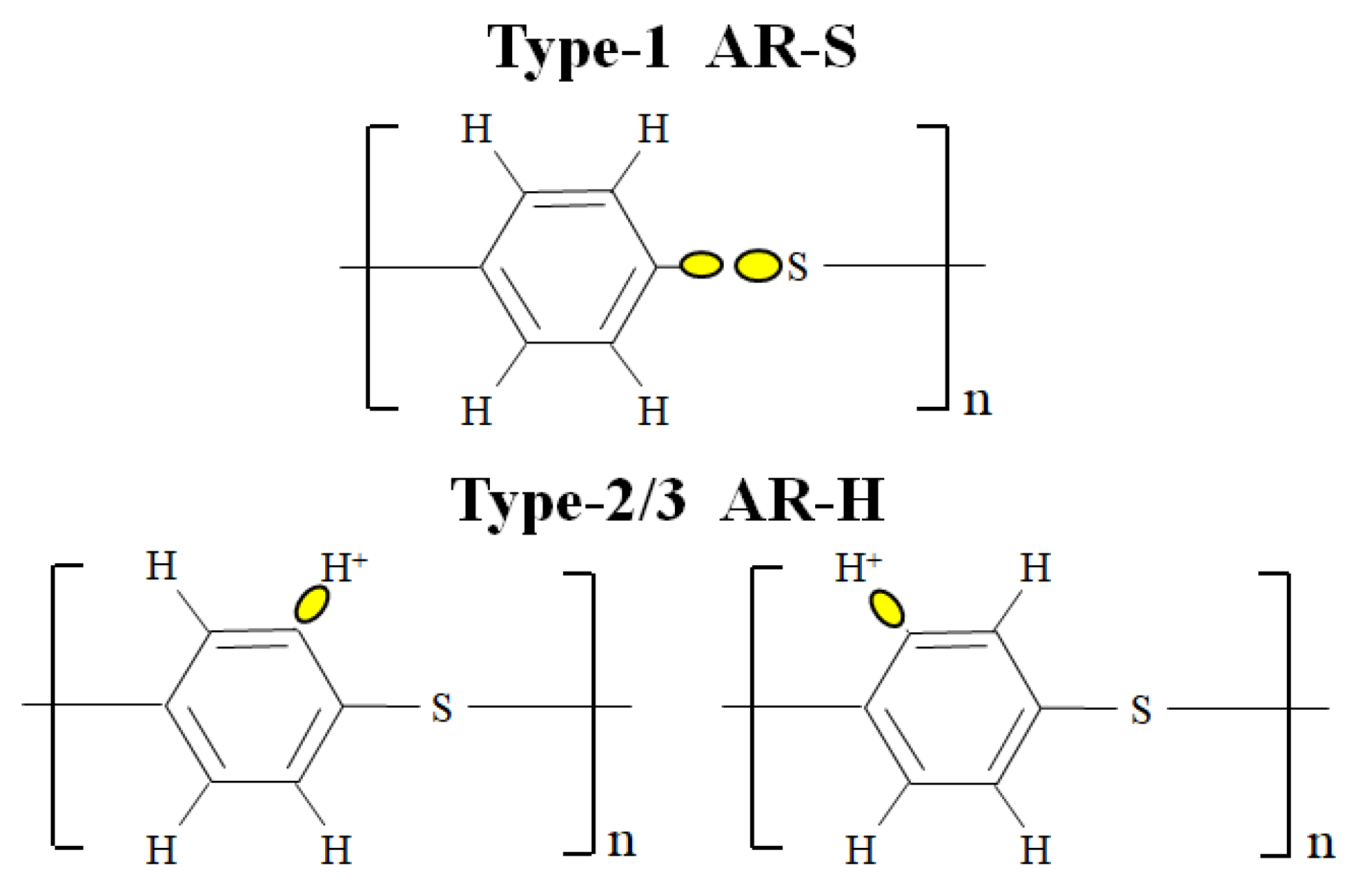
Figure 14 illustrates the three types of dangling bonds in PPS: AR-S designated “Type 1”; with AR-H designated “Type 2” and “Type 3”. Types 1, 2, and 3 refer to Peaks 1, 2, and 3 in Figure 13. Types 2 and 3 are regarded as identical, having identical location within the PPS macromolecule. The differences in B = 319.9 and 319.5 mT and their intensities in Figure 13 may be due to slightly different electrical configurations in the vicinity of the AR-H dangling bonds, brought about by movement probabilities between PPS macromolecules or within PPS macromolecules themselves, which is beyond the scope of this study. Henceforth, both Types 2 and 3 of AR-H will be referred to here as “Type 2/3” dangling bonds.

4.2. Model of Proposed Strengthening Mechanism by HLEBI in PPS Plies and at CF-PPS Interface

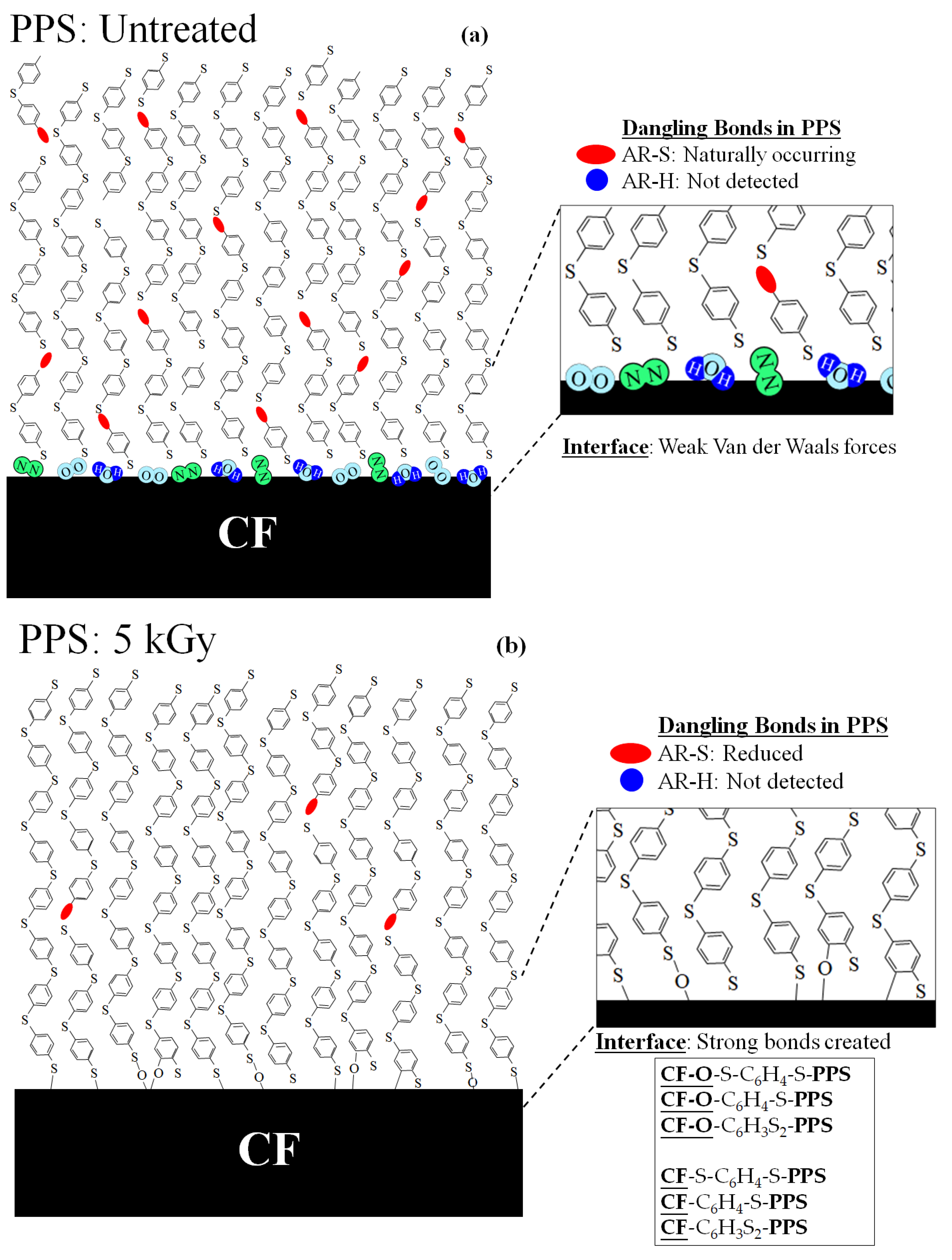
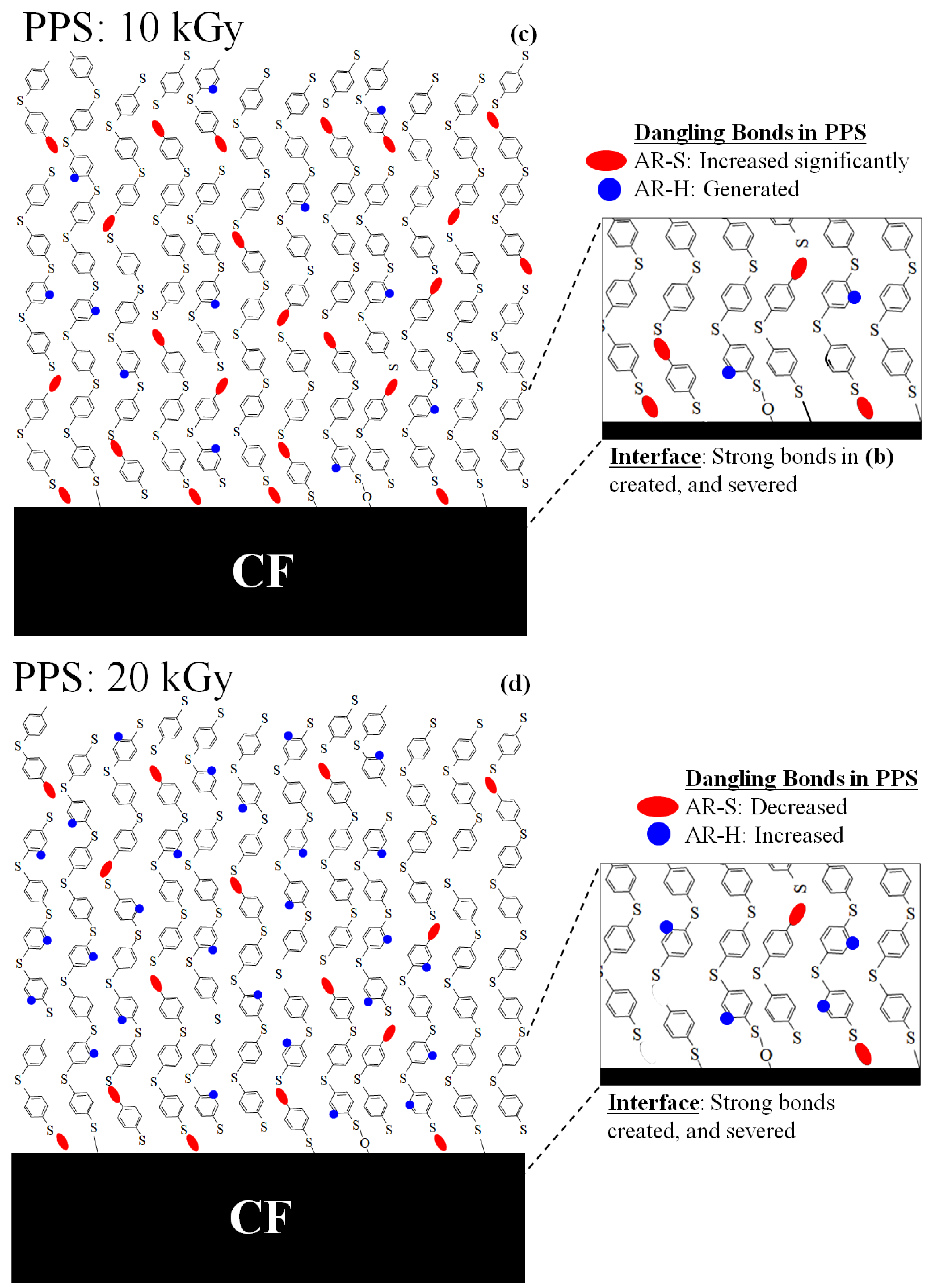
Figure 15 illustrates a molecular model of a proposed strengthening mechanism for [PPS]4[CF]3 by HLEBI in the PPS matrix and at CF/PPS interface. When Type-1 and Type 2/3 dangling bonds (Figure 14) correspond to 1st, 2nd, and 3rd ESR peaks (Figure 13), respectively, the strengthening mechanism of [PPS]4[CF]3 composite can be explained.
PPS: Untreated
Figure 15a illustrates untreated PPS with naturally occurring AR-S dangling bonds (ellipses) with no AR-H dangling bonds (dots). At the interface, weak Van der Waals forces from H2O, O2, and N2 gas molecules creating some adhesions are depicted.
PPS: 5 kGy
Figure 15b illustrates a reduced number of Type 1 AR-S dangling bonds in PPS by the 5 kGy HLEBI, with AR-H dangling bonds as non-existent. Decreased AR-S dangling bonds are assumed to be chain lengthening to strengthen the PPS matrix. In addition, at the interface, 5 kGy HLEBI is assumed to generate strong bonds, possibly covalent, from charge transfer from activated PPS to the highly conductive CF. Bonding of PPS is assumed to be with oxygen (O) in CF sizing or CF itself. Examples would be: CF-O-S-C6H4-S-PPS, CF-O-C6H4-S-PPS, and CF-O-C6H3S2-PPS; and with CF itself as CF-S-C6H4-S-PPS, CF-C6H4-S-PPS, and CF-C6H3S2-PPS, where “CF-O” is sizing, “CF” is CF surface, and “-C6Hx-“ is -AR-.
As mentioned earlier, similar to PPS, CF has naturally occurring dangling bonds that are reduced by HLEBI [30]. When HLEBI is directly applied to CFs, it has been reported to raise bending fracture strain [43,57], along with deformation resistivity, tensile strength, and strain of CF itself [44]. Since this study was with HLEBI applied to PPS only, it can be assumed that charge transfer occurs from PPS to CF to enhance the CF as well, to collectively strengthen the [PPS]4CF]3 composite.
PPS: 10 kGy
Figure 15c illustrates for the 10 kGy dose, increased AR-S and the appearance of AR-H dangling bond densities. The increased AR-S dangling bonds are apparently PPS chains being shortened. This, together with AR-H generation, apparently weakens the PPS matrix. In addition, at the CF/PPS interface, strong bonds are apparently created but also severed by the excess HLEBI dose; the net number is apparently reduced from that at 5 kGy. Therefore, the 10 kGy dose reduces auc.
PPS: 20 kGy
Figure 15d illustrates decreased AR-S dangling bonds at a 20 kGy dose compared to the 10 kGy, but still higher than untreated samples, again indicating shortened PPS chains. This, accompanied by an increase in AR-H dangling bonds, is assumed to weaken the PPS bulk below that at 10 kGy. At the CF/PPS interface, a higher number of strong bonds are apparently severed by the excess HLEBI dose, reducing auc below that at 10 kGy. At a higher dose of 30 kGy, it is assumed that AR-S and AR-H dangling bonds would be higher, since auc is reduced further.
Overall, Figure 15 illustrates the 5 kGy HLEBI dose apparently works best to strengthen the PPS itself in concert with the CF/PPS interface, increasing auc of the multilayered [PPS]4[CF]3 composite.

5. Conclusions

Since impacts such as hailstone, volcanic rock, bird strike, or also dropping tools can damage aircraft materials, a new strengthening process for an interlayered composite typically used in aerospace of carbon-fiber-reinforced thermoplastic polyphenylene sulfide polymer (CFRTP-PPS) was proposed to raise impact strength. This research aims to have application for commercial aircraft parts. Experimental results showed that when homogeneous low voltage electron beam irradiation (HLEBI) was applied to both sides of PPS plies prior to lamination assembly with untreated CF plies, and hot press, Charpy impact strength was increased. Samples were three CF plies alternating between four PPS plies, [PPS-CF-PPS-CF-PPS-CF-PPS] designated as [PPS]4[CF]3.
(1)
Applying 5 kGy-HLEBI to PPS improved Charpy impact strength (auc) at accumulative fracture probabilities Pf of 0.07, 0.50, and 0.93: from 13.1, 20.7, and 24.5 kJ m−2 to 20.1, 23.3, and 27.6 kJ m−2, respectively; increases of 53%, 12%, and 13%. The auc was improved most at the low-Pf of 0.07 (53%), indicating increased reliability by strengthening of the weakest samples in the data set.
(2)
The 3-dimensional Weibull analysis, often used for QC, showed the 5 kGy-HLEBI data set exhibited the highest as at Pf = 0 at 19.9 kJ m−2, indicating an increase in safety and reliability of the 5 kGy [PPS]4[CF]3 samples.
(3)
Optical microscopy along with SEM and EDS showed the 5 kGy HLEBI dose increased PPS/CF adhesion and increased cohesion within the interlayered structure to raise the impact strength.
(4)
A model was constructed to explain strengthening of PPS plies themselves and increased adhesion at the CF/PPS interface. (1) In the PPS matrix, reduced AR-S dangling bond density (which exists naturally in untreated PPS) acts to lengthen the chains as evidenced by a reduction in ESR peak with an inflection point at 320.3 mT. (2) At the CF/PPS interface, strong bonding is maximized in the form of CF-O-S-C6H4-S-PPS, CF-O-C6H4-S-PPS and CF-O-C6H3S2-PPS; and with CF itself, as CF-S-C6H4-S-PPS, CF-C6H4-S-PPS and CF-C6H3S2-PPS, where “CF-O” is sizing, “CF” is CF surface, and “-C6Hx-“ = -AR-. On the CF surface, EDS results detected sulfur, while SEM detected PPS remaining. This is instead of the weak intermolecular bonding CF(H2O, N2, O2)PPS of untreated samples. Since HLEBI doses above 10 kGy appear to degrade the composite, carefulness is always recommended in adjusting for optimum HLEBI dose for practical applications.
(5)
Specific future plans for this research are proprietary. However, in general, included are investigating specimens with different geometries, materials, tests, or treatments.

Author Contributions

Conceptualization, Y.N., H.K. and M.C.F.; methodology, Y.N., H.K., K.T., K.S. and E.M.; software, K.T., K.S., E.M. and H.K.; validation, M.C.F., H.K. and Y.N.; formal analysis, K.T. and H.K.; investigation, Y.N. and M.C.F.; resources, H.K., H.T.U., M.S. and Y.N.; data curation, H.K., M.C.F. and Y.N.; writing—original draft preparation, K.T., M.C.F., Y.N. and H.K.; writing—review and editing, M.C.F. and Y.N.; visualization, Y.N., M.C.F. and H.K.; supervision, M.S., Y.N., H.T.U. and H.K.; project administration, M.S., Y.N. and H.K.; funding acquisition, H.K., M.S. and Y.N. All authors have read and agreed to the published version of the manuscript.

Funding

This work was supported by the JST (Japan Science and Technology Agency) Project Title: Developments of Dissimilar Metal Joining Technology with Carbon Fiber: Grant No. [04-203].

Institutional Review Board Statement

Not applicable.

Informed Consent Statement

Not applicable.

Data Availability Statement

Data are available upon request from the corresponding author. There was no obligation to make the data publicly available during the course of this project.

Acknowledgments

The authors wish to thank Yasuo Miyamoto and Yoshiki Oda (ESR) of Tokai University, Shonan Campus for their useful help. We thank the library staff at Tokyo City University, Yokohama Campus for their great assistance. Our sincere gratitude also goes to Eye Electron Beam Co, Ltd. (Ghoda, Saitama, Japan) for their kind support with this project.

Conflicts of Interest

The authors declare no conflict of interest.

References

  1. Chiang, Y.-C.; Chen, Y.-J.; Wu, C.-Y. Effect of Relative Humidity on Adsorption Breakthrough of CO2 on Activated Carbon Fibers. Materials 2017, 10, 1296. [Google Scholar] [CrossRef] [Green Version]
  2. Kamedulski, P.; Lukaszewicz, J.P.; Witczak, L.; Szroeder, P.; Ziolkowski, P. The Importance of Structural Factors for the Electrochemical Performance of Graphene/Carbon Nanotube/Melamine Powders towards the Catalytic Activity of Oxygen Reduction Reaction. Materials 2021, 14, 2448. [Google Scholar] [CrossRef] [PubMed]
  3. Irshad, H.M.; Hakeem, A.S.; Raza, K.; Baroud, T.N.; Ehsan, M.A.; Ali, S.; Tahir, M.S. Design, Development and Evaluation of Thermal Properties of Polysulphone–CNT/GNP Nanocomposites. Nanomaterials 2021, 11, 2080. [Google Scholar] [CrossRef] [PubMed]
  4. Zhang, K.; Zhang, G.; Liu, B.; Wang, X.; Long, S.; Yang, J. Effect of aminated polyphenylene sulfide on the mechanical properties of short carbon fiber reinforced polyphenylene sulfide composites. Compos. Sci. Technol. 2014, 98, 57–63. [Google Scholar] [CrossRef]
  5. Dong, Y.; Yu, T.; Wang, X.-J.; Zhang, G.; Lu, J.-H.; Zhang, M.-L.; Long, S.-R.; Yang, J. Improved interfacial shear strength in polyphenylene sulfide/carbon fiber composites via the carboxylic polyphenylene sulfide sizing agent. Compos. Sci. Technol. 2020, 190, 108056. [Google Scholar] [CrossRef]
  6. Díez-Pascual, A.M.; Naffakh, M. Towards the development of poly(phenylene sulphide) based nanocomposites with enhanced mechanical, electrical and tribological properties. Maters. Chem. Phys. 2012, 135, 348–357. [Google Scholar] [CrossRef] [Green Version]
  7. Soni, S.K.; Thomas, B.; Swain, A.; Roy, T. Functionally graded carbon nanotubes reinforced composite structures: An extensive review. Compos. Struct. 2022, 299, 116075. [Google Scholar] [CrossRef]
  8. Yang, X.; Chen, Y.; Zhang, C.; Duan, G.; Jiang, S. Electrospun carbon nanofibers and their reinforced composites: Preparation, modification, applications, and perspectives. Compos. B Eng. 2023, 249, 110386. [Google Scholar] [CrossRef]
  9. Chen, G.; Mohanty, A.K.; Misra, M. Progress in research and applications of polyphenylene sulfide blends and composites with carbons. Compos. Part B 2021, 209, 108553. [Google Scholar] [CrossRef]
  10. Ou, Y.; Wu, L.; Yi, X.; Mao, D. Understanding Mode I interlaminar toughening of unidirectional CFRP laminates interleaved with aligned ultrathin CNT fiber veils: Thickness and orientation effects. Compos. B Eng. 2023, 254, 110578. [Google Scholar] [CrossRef]
  11. Mahat, K.B.; Alarifi, I.; Alharbi, A.; Asmatulu, R. Effects of UV Light on Mechanical Properties of Carbon Fiber Reinforced PPS Thermoplastic Composites. Macromol. Symp. 2016, 365, 157–168. [Google Scholar] [CrossRef]
  12. McKague, L. Thermoplastic Resins; Composites Consulting Inc.: DeSoto, TX, USA, 1990; Volume 1, p. 132. [Google Scholar]
  13. Newaz, G.M. Advances in Thermoplastic Matrix Composite Materials; ASTM International: Philadelphia, PA, USA, 1989; Volume 1, p. 1. [Google Scholar]
  14. Rahate, A.S.; Nemade, K.R.; Waghuley, S.A. Polyphenylene sulfide (PPS): State of the art and applications. Rev. Chem. Eng. 2013, 29, 471–489. [Google Scholar] [CrossRef]
  15. Zhu, C.; Zhang, J.; Qiu, S.; Jia, Y.; Wang, L.; Wang, H. Tailoring the pore size of polyphenylene sulfide nonwoven with bacterial cellulose (BC) for heat-resistant and high-wettability separator in lithium-ion battery. Comp. Comm. 2021, 24, 100659. [Google Scholar] [CrossRef]
  16. Kishore, V.; Chen, X.; Hassen, A.A.; Lindahl, J.; Kunc, V.; Duty, C. Post-process annealing of large-scale 3D printed polyphenylene sulfide composites. Addit. Manuf. 2020, 35, 101837. [Google Scholar] [CrossRef]
  17. Parker, M.; Inthavong, A.; Lew, E.; Waddell, S.; Ezeokeke, N.; Matsuzaki, R.; Arola, D. 3D printing of continuous carbon fiber reinforced polyphenylene sulfide: Exploring printability and importance of fiber volume fraction. Addit. Manuf. 2022, 54, 102763. [Google Scholar] [CrossRef]
  18. Oshima, S.; Higuchi, R.; Kato, M.; Minakuchi, S.; Yokozeki, T.; Aoki, T. Cooling rate-dependent mechanical properties of polyphenylene sulfide (PPS) and carbon fiber reinforced PPS (CF/PPS). Compos. A Appl. Sci. Manuf. 2023, 164, 107250. [Google Scholar] [CrossRef]
  19. Kiss, P.; Glinz, J.; Stadlbauer, W.; Burgstaller, C.; Archodoulaki, V.M. The effect of thermally desized carbon fibre reinforcement on the flexural and impact properties of PA6, PPS and PEEK composite laminates: A comparative study. Compos. B Eng. 2021, 215, 108844. [Google Scholar] [CrossRef]
  20. Lacoma, V.; Bailleul, J.-L.; Moisan, S.; Vincent, G.; Binetruy, C.; Kerbrat, O. Inventory analysis of the carbon fibres reinforced polyphenylene sulfide thermo-stamping manufacturing process. J. Clean. Prod. 2023, 393, 136337. [Google Scholar] [CrossRef]
  21. Benson, S.W. Bond energies. J. Chem. Educ. 1965, 42, 502–518. [Google Scholar] [CrossRef]
  22. James, A.; Lord, M. Macmillan’s Chemical and Physical Data; The Macmillan Press, Ltd.: London, UK; Basingstoke, UK, 1992; pp. 484–485. ISBN 0-333-51167-0. [Google Scholar]
  23. Gardiner, G. Thermoplastic Composite the Inside Story. High Perform. Compos. 2009, 1, 8. [Google Scholar]
  24. Nishi, Y.; Kitagawa, S.; Faudree, M.C.; Uchida, H.T.; Kanda, M.; Takase, S.; Kaneko, S.; Endo, T.; Tonegawa, A.; Salvia, M.; et al. Improvements of strength of layered polypropylene reinforced by carbon fiber by its sizing film and electron beam under protective nitrogen gas atmosphere. In Carbon Related Materials; Kaneko, S., Aono, M., Pruna, A., Can, M., Mele, P., Ertugrul, M., Endo, T., Eds.; Springer: Singapore, 2021; pp. 279–302. [Google Scholar]
  25. Tang, L.-G.; Kardos, J.L. A review of methods for improving the interfacial adhesion between carbon fiber and polymer matrix. Polym. Compos. 1997, 18, 100–113. [Google Scholar] [CrossRef]
  26. Jones, C. Effects of electrochemical and plasma treatments on carbon fibre surfaces. Surf. Interf. Anal. 1993, 20, 357–367. [Google Scholar] [CrossRef]
  27. Pittman, C.U., Jr.; Jiang, W.; Yue, Z.R.; Gardner, S.; Wang, L.; Toghiani, H.; Leon y Leon, C.A. Surface properties of electrochemically oxidized carbon fibers. Carbon 1999, 37, 1797–1807. [Google Scholar] [CrossRef]
  28. Park, S.J.; Kim, B.J. Roles of acidic functional groups of carbon fiber surfaces in enhancing interfacial adhesion behavior. Mater Sci Eng A 2005, 408, 269–274. [Google Scholar] [CrossRef]
  29. Takei, H.; Salvia, M.; Vautrin, A.; Tonegawa, A.; Nishi, Y. Effects of electron beam irradiation on elasticity of CFRTP (CF/PEEK). Mater. Trans. 2011, 52, 734–739. [Google Scholar] [CrossRef] [Green Version]
  30. Nishi, Y.; Takei, H.; Iwata, K.; Salvia, M.; Vautrin, A. Effects of electron beam irradiation on impact value of carbon fiber reinforced thermoplastic polyetheretherketone. Mater. Trans. 2009, 50, 2826–2832. [Google Scholar] [CrossRef] [Green Version]
  31. Nomura, R.; Kanda, M.; Faudree, M.C.; Jimbo, I.; Nishi, Y. Improving impact value of interlayered glass fiber chopped strand mat reinforced thermoplastic polypropylene externally irradiated by homogeneous low potential electron beam. Mater. Trans. 2014, 57, 1915–1921. [Google Scholar] [CrossRef] [Green Version]
  32. Nishi, Y.; Kobayashi, H.; Salvia, M. Effects of Electron Beam Irradiation on Charpy Impact Value of GFRP. Mater. Trans. 2007, 48, 1924–1927. [Google Scholar] [CrossRef] [Green Version]
  33. Faudree, M.; Nishi, Y.; Gruskiewicz, M. Effects of electron beam irradiation on Charpy impact value of short glass fiber (GFRP) samples with random distribution of solidification texture angles from zero to 90 degrees. Mater. Trans. 2012, 53, 1412–2310. [Google Scholar] [CrossRef] [Green Version]
  34. Mizutani, A.; Nishi, Y. Improved strength in carbon fiber reinforced plastics due after electron beam irradiation. Mater. Trans. 2003, 44, 1857–1860. [Google Scholar] [CrossRef] [Green Version]
  35. Nishi, Y.; Inoue, K.; Salvia, M. Improvement of Charpy Impact of Carbon Fiber Reinforced Polymer by Low Energy Sheet Electron Beam Irradiation. Mater. Trans. 2006, 47, 2846–2851. [Google Scholar] [CrossRef] [Green Version]
  36. Nishi, Y.; Toriyama, T.; Oguri, K.; Tonegawa, A.; Takayama, K. High fracture resistance of carbon fiber treated by electron beam irradiation. J. Mater. Res. 2001, 16, 1632–1635. [Google Scholar] [CrossRef]
  37. Nishi, Y.; Mizutani, A.; Kimura, A.; Toriyama, T.; Oguri, K.; Tonegawa, A. Effects of sheet electron beam irradiation on aircraft design stress of carbon fiber. J. Mater. Sci. 2003, 38, 89–92. [Google Scholar] [CrossRef]
  38. Kimura, H.; Takeda, K.; Uchida, H.T.; Faudree, M.C.; Sagawa, K.; Kaneko, S.; Salvia, M.; Nishi, Y. Strengthening process by electron beam to carbon fiber for impact strength enhancement of interlayered thermoplastic polypropylene carbon fiber composite. Materials 2022, 15, 7620. [Google Scholar] [CrossRef]
  39. Faudree, M.C.; Uchida, H.T.; Kimura, H.; Kaneko, S.; Salvia, M.; Nishi, Y. Advances in Titanium/Polymer Hybrid Joints by Carbon Fiber Plug Insert: Current Status and Review. Materials 2022, 15, 3220. [Google Scholar] [CrossRef] [PubMed]
  40. Hasegawa, H.; Faudree, M.C.; Enomoto, Y.; Takase, S.; Kimura, A.; Tonegawa, A.; Jimbo, I.; Salvia, M.; Nishi, Y. Enhanced tensile strength of Titanium/Polycarbonate joint connected by electron beam activated cross-weave carbon fiber cloth insert. Mater. Trans. 2017, 58, 1606–1615. [Google Scholar] [CrossRef] [Green Version]
  41. Hasegawa, H.; Faudree, M.C.; Matsumuara, Y.; Jimbo, I.; Nishi, Y. Tensile Strength of a Ti/Thermoplastic ABS Matrix CFRTP Joint Connected by Surface Activated Carbon Fiber Cross-Weave Irradiated by Electron Beam. Mater. Trans. 2016, 57, 1202–1208. [Google Scholar] [CrossRef] [Green Version]
  42. Nomura, R.; Kanda, M.; Faudree, M.C.; Jimbo, I.; Nishi, Y. Internal activation of thermoplastic polypropylene GFRTP composite by homogeneous low energy electron beam irradiation (HLEBI) of the interlayered glass fiber chopped strand mats (GF-CSM) prior to assembly. Mater. Trans. 2016, 57, 417–422. [Google Scholar] [CrossRef] [Green Version]
  43. Nishi, Y.; Iwata, K. Effects of electron beam irradiation on impact value for soda glass. Mater. Trans. 2005, 46, 2241–2245. [Google Scholar] [CrossRef] [Green Version]
  44. Iwata, K.; Nishi, Y. Effects of electron beam irradiation on impact value of borosilicate glass. Mater Trans 2010, 51, 121–127. [Google Scholar] [CrossRef] [Green Version]
  45. Strong, A.B.; Black, S.R.; Bryce, G.R.; Olcott, D.D. Crosslinking of thermoplastic composites using electron beam radiation. Soc. Adv. Mater. Process Eng. (SAMPE) Q. 1991, 22, 45–54. [Google Scholar]
  46. Technical Sheet for CF. Available online: https://shop.lab-cast.com/?pid=93479046 (accessed on 15 March 2023).
  47. Kitagawa, S.; Kimura, H.; Takase, S.; Tsuyuki, N.; Kitahara, D.; Takahashi, A.; Faudree, M.C.; Uchida, H.T.; Tonegawa, A.; Kanda, M.; et al. Tensile strength of polypropylene reinforced by carbon fiber covered with and without sizing epoxy film. Trans. Mat. Res. Soc. Jpn. 2018, 43, 125–128. [Google Scholar] [CrossRef] [Green Version]
  48. Sastri, V.R. Ch. 8 High temperature engineering thermoplastics. In Plastics in Medical Devices: Properties, Requirements and Applications, 2nd ed.; Elsevier: Amsterdam, The Netherlands, 2014; pp. 173–213. [Google Scholar]
  49. Christenhusz, R.; Reimer, L. Schichtdickenabhangigkeit der warmerzeugungdurch elektronenbestrahlung im energiebereich zwischen 9 und 100 keV (Layer thickness dependency of heat generation by electron irradiation in the energy range between 9 and 100 keV). Z. Angew. Phys. 1967, 23, 396–404. [Google Scholar]
  50. Japanese Industrial Standard JIS K 7077; Testing Method for Charpy Impact Strength Ofcarbon Fiber Reinforced Plastics. Japanese Standards Association: Tokyo, Japan, 1991.
  51. Faudree, M.C.; Nishi, Y.; Gruskiewicz, M.; Salvia, M. A New Glass Fibered Reinforced Composite with Improved Charpy Impact Properties at Low and High Temperatures beyond the Extremes of Aircraft Flight. Mater. Trans. 2018, 59, 1280–1287. [Google Scholar] [CrossRef] [Green Version]
  52. Nishida, T.; Yasuda, E. Evaluation of Dynamic Properties of Ceramics (In Japanese, Ceramics No Rikigaku Tokusei Hyouka); Nikkan Kogaku Shimbun Sha: Tokyo, Japan, 1986; pp. 50–51. (In Japanese) [Google Scholar]
  53. Weibull, W. A Statistical Theory of the Strength of Materials; Ingeniörs vetenskaps akademien; nr. 153; (Generalstabens litografiska anstalts förlag); Engineer Science Academy, Lithographic Institution Publisher: Stockholm, Sweden, 1939; pp. 16–22. [Google Scholar]
  54. Ichikawa, M. Some Problems in Application of Three-Parameter Weibull Distributions to Reliability Evaluation of Ceramics. Jpn. Soc. Mech. Engrs. (JSME) Intl. J. 1992, 35, 12–21. [Google Scholar]
  55. Nishi, Y.; Ourahmoune, R.; Kanda, M.; Quan, J.; Faudree, M.C.; Salvia, M. Improvement of Bending Modulus and Impact Value in Injection-Molded Short Carbon Fiber Reinforced Polyetheretherketone with Homogeneous Low-Voltage Electron Beam Irradiation. Mater. Trans. 2014, 55, 1304–1310. [Google Scholar] [CrossRef] [Green Version]
  56. Schlick, S.; Jeschke, G. 2.08 Electron Spin Resonance Spectroscopy. In Polymer Science: A Comprehensive Reference; Matyjaszewski, K., Möller, M., Eds.; Elsevier Science: Amsterdam, The Netherlands, 2012; pp. 221–253. ISBN 978-0-08-087862-1. [Google Scholar]
  57. Nishi, Y.; Mizutani, A.; Uchida, N. Electron Beam Strengthening for Carbon Fiber-Reinforced Composite Materials. J. Thermoplast. Compos. Mater. 2004, 17, 289–302. [Google Scholar] [CrossRef]
Figure 1. Constitutional formula of PPS: for untreated (a) and with reported bonding dissociation energies (BDE) [21,22] at dangling bond sites (b). For (b), ‘AR-’ is the neighboring aromatic ring (-C6H5), where the ~285 [21] and ~461 kJ mol−1 [22] bonds are referred to here as “AR-S” and “AR-H”, respectively.
Materials 16 02823 g001
Figure 2. Fabrication steps for HLEBI-treated [PPS]4[CF]3 interlayered composite.
Materials 16 02823 g002
Figure 3. Schematic diagram of electron curtain processer. (Iwasaki Electric Group Co., Ltd., Tokyo, Japan).
Materials 16 02823 g003
Figure 4. Schematic of the Charpy impact machine (Shimadzu Corporation No.51735, Tokyo, Japan) taken from Faudree, Nishi, Gruskiewicz, Salvia (2018) [51]. Angles α ανδ β are exaggerated for clarity.
Materials 16 02823 g004
Figure 5. Plot of accumulative probability, Pf vs. Charpy impact strength, auc (kJ m−2) as a function of HLEBI dose.
Materials 16 02823 g005
Figure 6. Effect of HLEBI irradiation dose on experimental impact strength (auc) at low- (Pf = 0.07), median- (0.50), and high- (0.93) fracture probabilities for untreated and HLEBI-irradiated [PPS]4[CF]3 samples, respectively.
Materials 16 02823 g006
Figure 7. Iteration of potential lowest imact strength (eas) to obtain statistically lowest impact strength as (auc at Pf = 0) when correlation coefficient F reaches the maximum (arrows) (a); and linear relationships between ln(aucas) and ln[-ln(1 − Pf)] from the 3-dimensional Weibull calculation (b).
Materials 16 02823 g007
Figure 8. Optical microscope photos of damage zones (side view) of untreated (a) and 5 kGy (b) [PPS]4[CF]3 samples, respectively. Arrows show Charpy impact direction.
Materials 16 02823 g008
Figure 9. Optical microscope photos of tensile sides of untreated (a) and 5 kGy [PPS]4[CF]3 samples (b,c), respectively.
Materials 16 02823 g009
Figure 10. Optical microscope photos of tensile side of untreated (a) and 5 kGy (b) [PPS]4[CF]3 samples, respectively, showing a close-up of the main crack.
Materials 16 02823 g010
Figure 11. SEM photomicrographs of untreated (0 kGy) (a) and 10 kGy (b) [PPS]4[CF]3 samples, respectively.
Materials 16 02823 g011
Figure 12. EDS mapping of fracture surfaces of untreated (a) 5 kGy (b) and 10 kGy (c) [PPS]4[CF]3 samples, respectively.
Materials 16 02823 g012
Figure 13. ESR signals of untreated samples (0 kGy) and those with the HLEBI dose (kGy) to PPS. Peaks 1, 2, and 3 corresponding to dangling bonds are indicated.
Materials 16 02823 g013
Figure 14. Constitutional formula of PPS with three types of dangling bonds assumed from Figure 13.
Materials 16 02823 g014
Figure 15. Proposed model of a strengthening mechanism by HLEBI within the PPS matrix and at the CF/PPS interface for: (a) untreated, (b) 5 kGy, (c) 10 kGy, and (d) 20 kGy [PPS]4[CF]3 samples, respectively. AR-S and AR-H dangling bonds are modelled as red ellipses and blue dots, respectively. Note that the number of bonds shown is arbitrary; the purpose is just to model trends by the HLEBI.
Materials 16 02823 g015aMaterials 16 02823 g015b
Table 1. Charpy impact strength, auc (kJ m−2) and Pf for individual specimens from the data in Figure 5.
Pfauc (kJ m−2)
Unt’d5 kGy10 kGy20 kGy30 kGy
0.0713.120.114.713.08.8
0.1816.920.514.718.211.7
0.2918.320.817.718.315.1
0.3918.323.319.819.315.4
0.5020.723.320.819.516.3
0.6123.825.921.320.017.6
0.7124.126.522.820.318.8
0.8224.326.523.820.519.6
0.9324.527.624.322.521.3
Table 2. Summary of the effect of the HLEBI dose on ESR signal intensities in PPS and auc at Pf = 0.50 of the [PPS]4[CF]3 composite. BDE values of AR-S and AR-H (kJmol−1) from [21,22] are shown.
HLEBI Dose
(kGy)
AR-S
Peak 1
~285 kJmol−1
AR-H
Peaks 2 and 3
~461 kJmol−1
auc at Pf = 0.50
(kJ m−2)
0YESNO20.7
5<UNTREATEDNO23.3
10>>UNTREATEDYES20.8
15>UNTREATEDYES-
20>UNTREATEDYES19.5
Disclaimer/Publisher’s Note: The statements, opinions and data contained in all publications are solely those of the individual author(s) and contributor(s) and not of MDPI and/or the editor(s). MDPI and/or the editor(s) disclaim responsibility for any injury to people or property resulting from any ideas, methods, instructions or products referred to in the content.