
A Review of Transition Metal Sulfides as Counter Electrodes for Dye-Sensitized and Quantum Dot-Sensitized Solar Cells

 ,
,  ,
,  , and
, and
Abstract
:1. Introduction
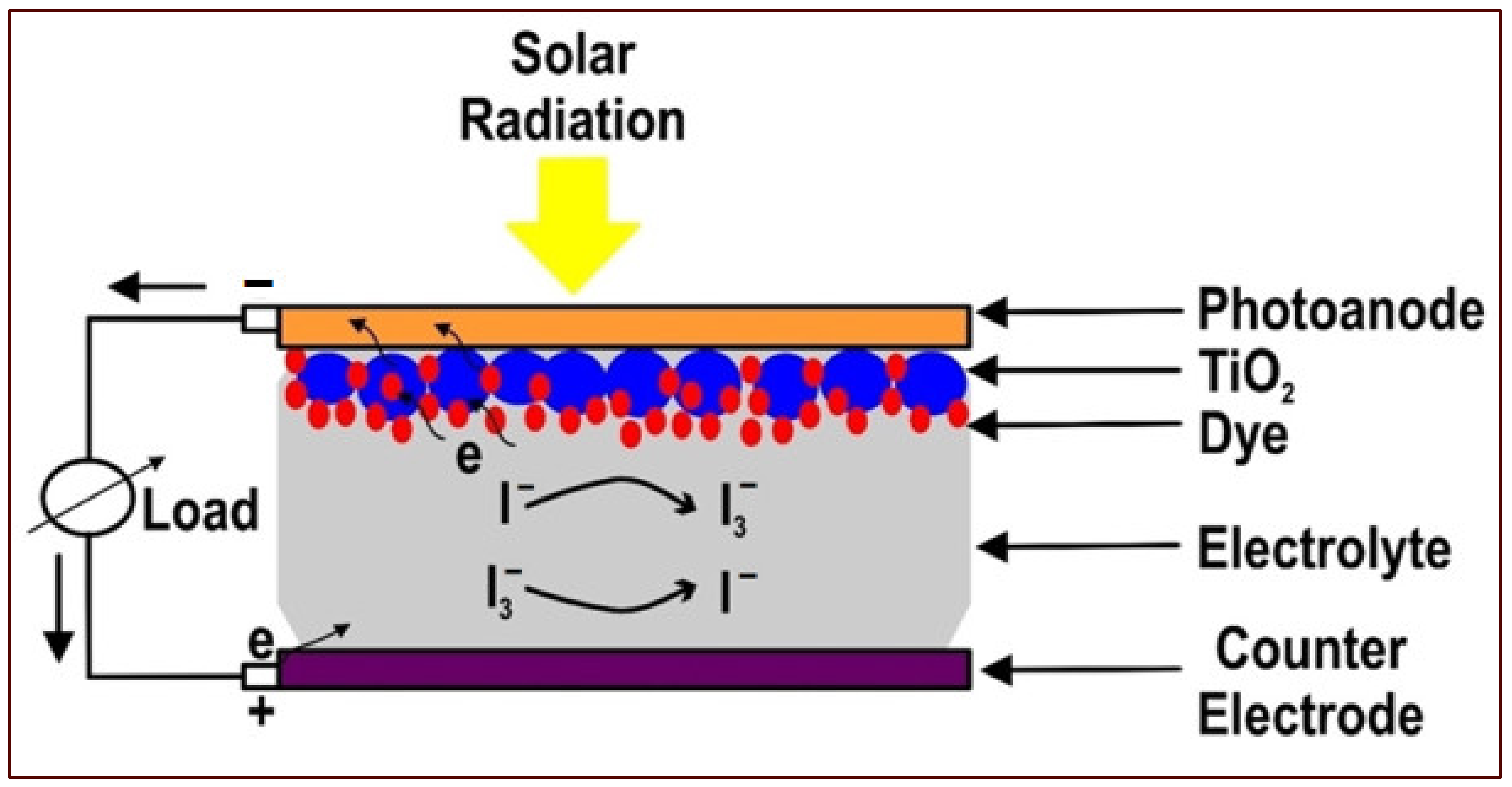
2. DSSCs
- A working electrode consists of a transparent conductive oxide (TCO) glass substrate sheet treated with a mesoporous oxide layer to activate electronic conduction.
- Molecular dye covalently bonded to the TCO for enhancement of light absorption.
- Redox mediator-based electrolyte to enable regeneration of oxidized dye molecules.
- Cathode electrodes consisting of TCO are mainly coated with platinum (Pt) to facilitate the collection of electrons.
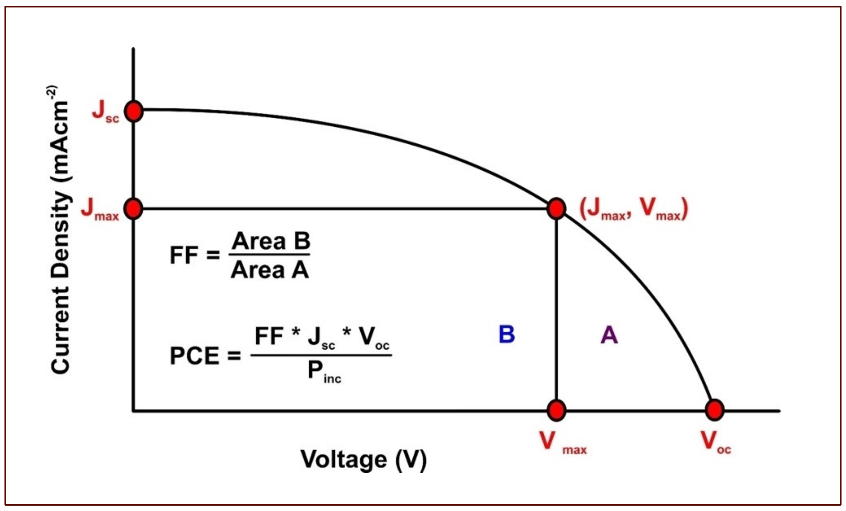
- Incident photon to current conversion efficiency (IPCE)
- Short circuit current (Isc)
- Open circuit voltage (Voc)
- Maximum power output (Pmax), which is a product of maximum voltage (Vmax) and maximum current (Imax)
- Overall efficiency (η), which represents the percentage of solar energy converted into electrical energy
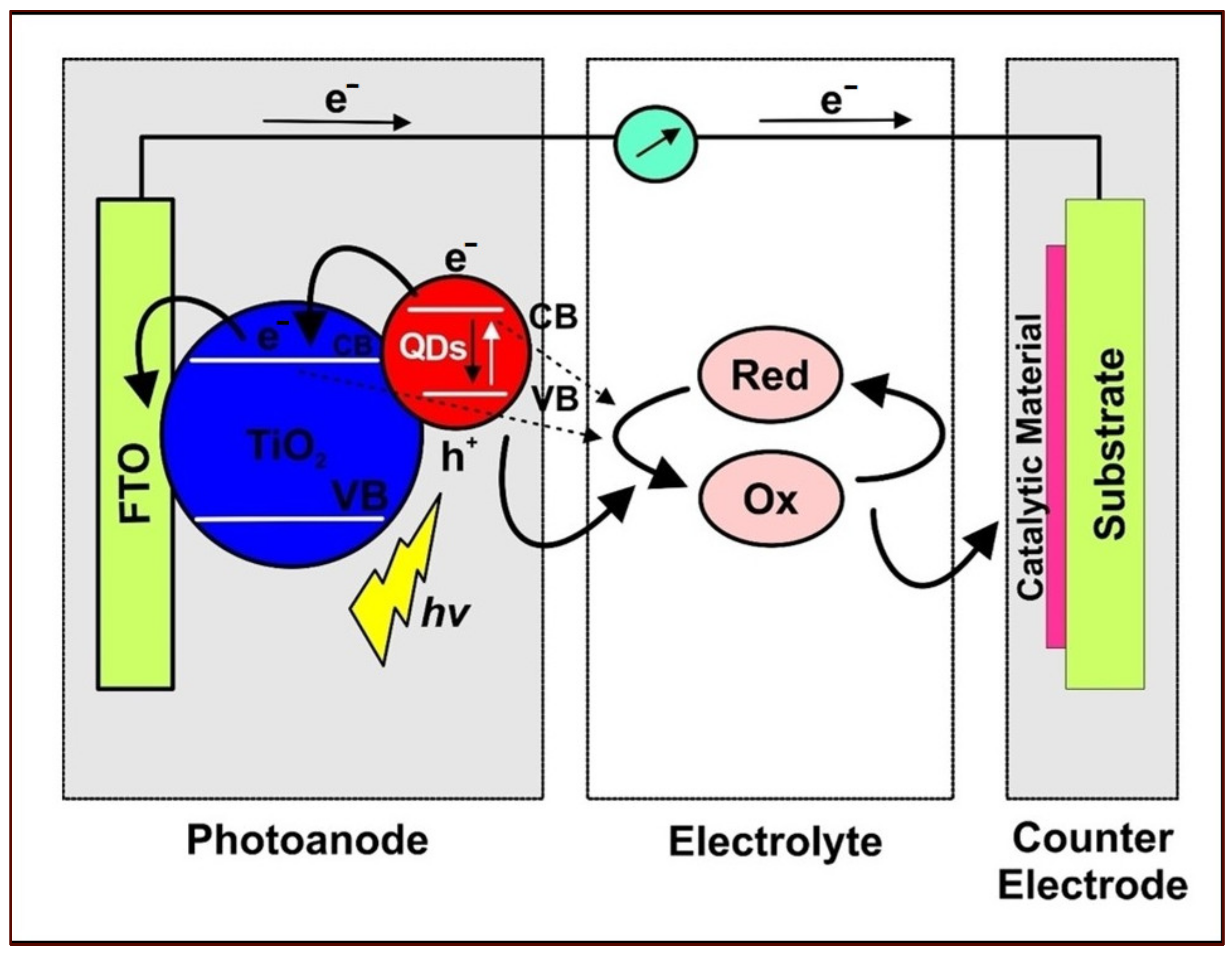
3. QDSSC
4. Transition Metal Chalcogenides (TMCs) Compounds-Based CE Catalysts
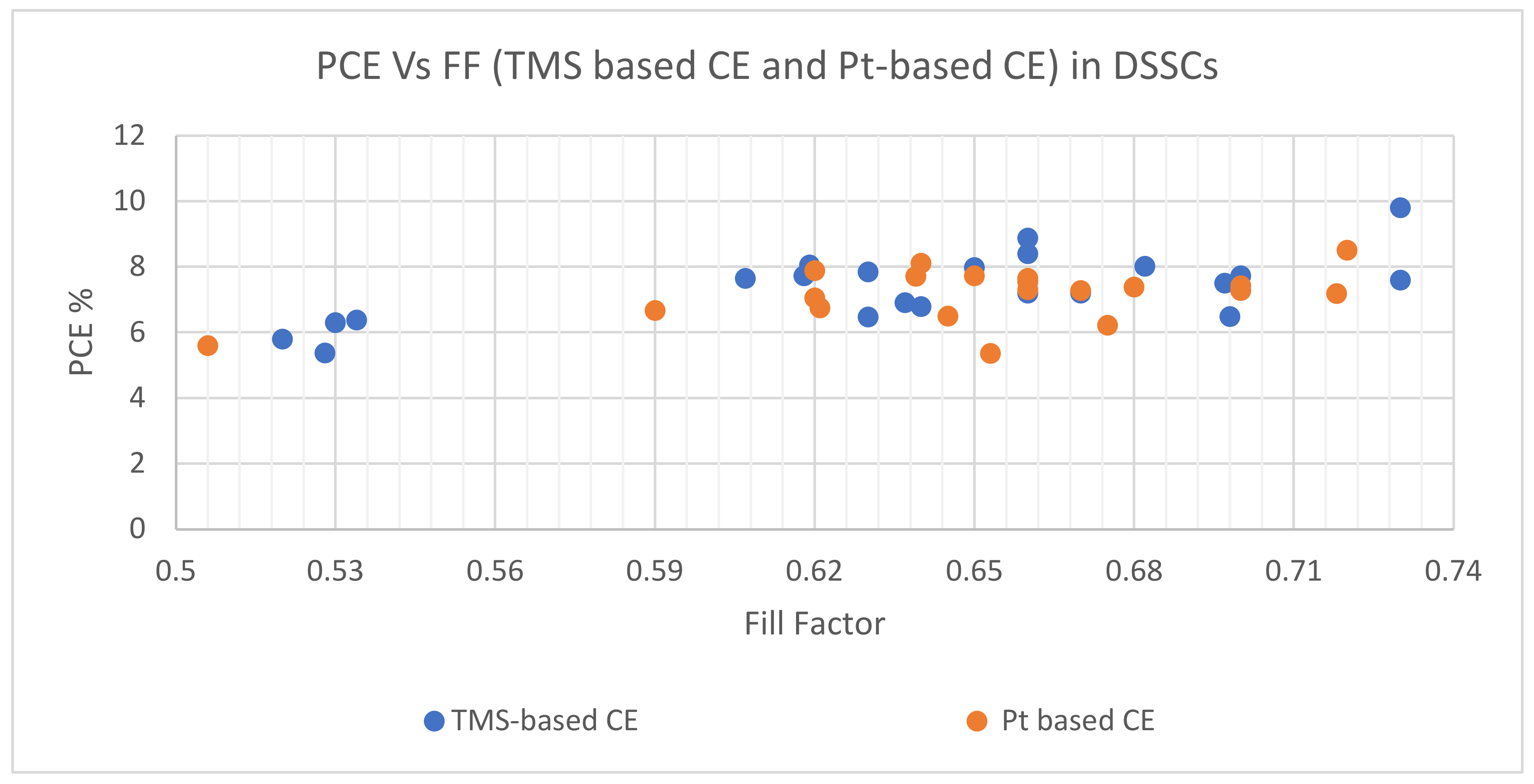
4.1. The TMS-Based CEs Applications in DSSCs
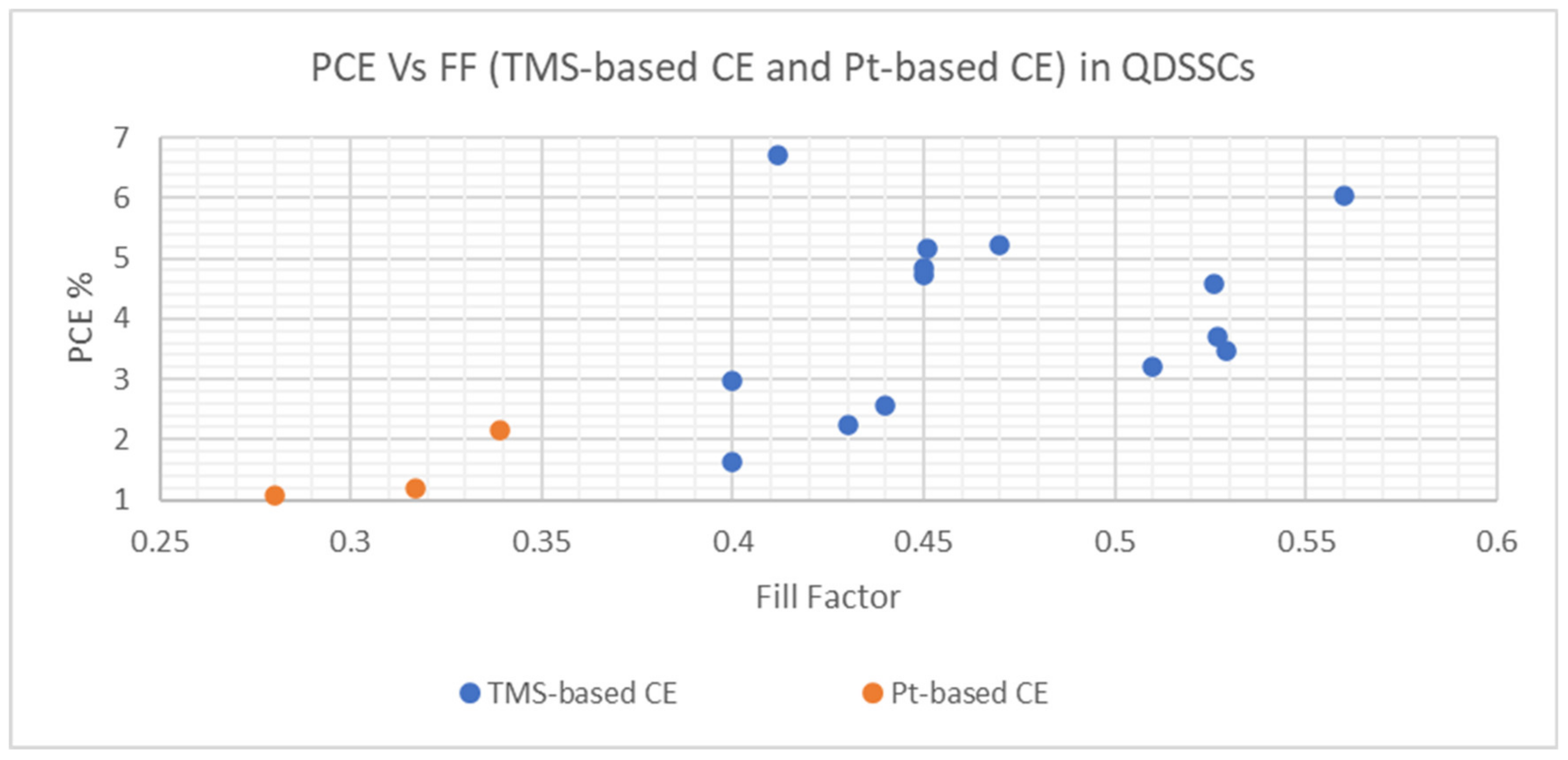
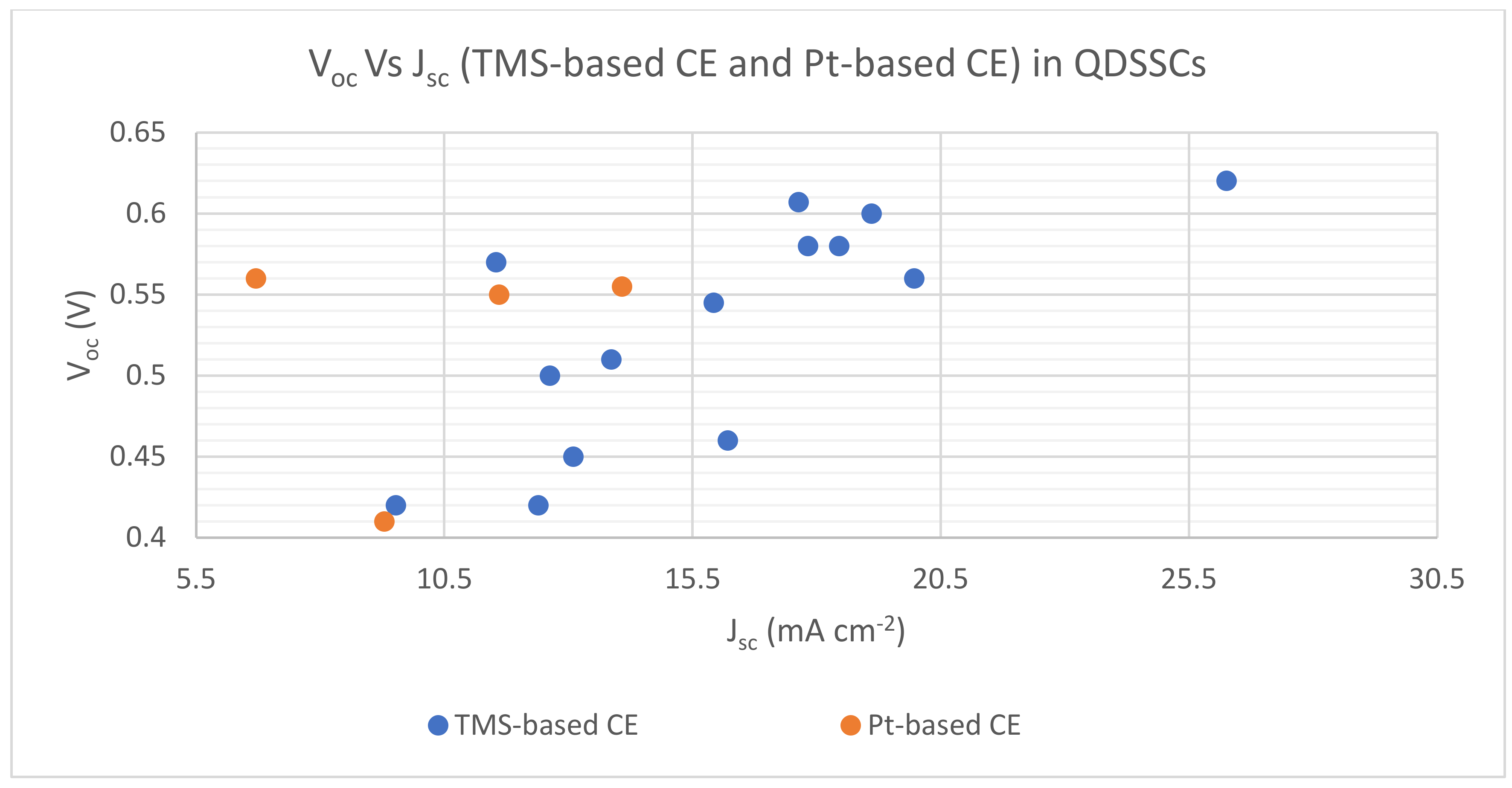
4.2. TMS-Based CEs Applications in QDSSCs
5. Conclusions and Perspectives
Author Contributions
Funding
Institutional Review Board Statement
Informed Consent Statement
Data Availability Statement
Acknowledgments
Conflicts of Interest
Nomenclature
| CB | Conduction Band |
| CBD | Chemical Bath Deposition |
| CE | Counter Electrode |
| CNTs | Carbon Nanotubes |
| DSSCs | Dye-Sensitized Solar Cells |
| FTO | Fluorine-Doped-Tin Oxide |
| GH | Graphene Hydrogel |
| GP | Graphite Paper |
| HTS | Hierarchical TiO2 Spheres |
| HOMO | Highest Occupied Molecular Orbital |
| IPCE | Incident-Photon-To-Electron Conversion Efficiency |
| LUMO | Lowest Occupied Molecular Orbital |
| MEG | Multiple Excitons Generation |
| NPs | Nanoparticles |
| NSs | Nanosheets |
| NRs | Nanorods |
| NTs | Nanotubes |
| PCE | Power Conversion Efficiency |
| Pt | Platinum |
| PV | Photovoltaic |
| QDs | Quantum Dots |
| QDSSCs | Quantum Dot-Sensitized Solar Cells |
| SILAR | Successive Ionic Layer Adsorption and Reaction |
| TCO | Transparent Conductive Oxide |
| TMCs | Transition Metal Chalcogenides |
| TMDs | Transition Metal Dichalcogenides |
| TMSs | Transition Metal Sulfides |
| VB | Valence Band |
| Jsc | Short-Circuit Current Density |
| Rct | Charge Transfer Resistance |
| Voc | Open Circuit Voltage |
References
- Lee, W.; Kang, S.H.; Min, S.K.; Sung, Y.E.; Han, S.H. Co-sensitization of vertically aligned TiO2 nanotubes with two different sizes of CdSe quantum dots for broad spectrum. Electrochem. Commun. 2008, 10, 1579–1582. [Google Scholar] [CrossRef]
- Hasanuzzaman, M.; Rahim, N.A.; Hosenuzzaman, M.; Saidur, R.; Mahbubul, I.M.; Rashid, M.M. Energy savings in the combustion-based process heating in industrial sector. Renew. Sustain. Energy Rev. 2012, 16, 4527–4536. [Google Scholar] [CrossRef]
- Hosenuzzaman, M.; Rahim, N.A.; Selvaraj, J.; Hasanuzzaman, M.; Malek, A.B.M.A.; Nahar, A. Global prospects, progress, policies, and environmental impact of solar photovoltaic power generation. Renew. Sustain. Energy Rev. 2015, 41, 284–297. [Google Scholar] [CrossRef]
- Nguyen, K.Q. Alternatives to grid extension for rural electrification: Decentralized renewable energy technologies in Vietnam. Energy Policy. 2007, 35, 2579–2589. [Google Scholar] [CrossRef]
- European Commission. Renewable Energy Targets. 2022. Available online: https://ec.europa.eu/energy/en/topics/renewable-energy (accessed on 15 November 2022).
- Gentilini, D.; D’Ercole, D.; Gagliardi, A.; Brunetti, A.; Reale, A.; Brown, T.; Di Carlo, A. Analysis and simulation of incident photon to current efficiency in dye sensitized solar cells. Superlattices Microstruct. 2010, 47, 192–196. [Google Scholar] [CrossRef]
- Maddah, H.A.; Berry, V.; Behura, S.K. Biomolecular photosensitizers for dye-sensitized solar cells: Recent developments and critical insights. Renew. Sustain. Energy Rev. 2020, 121, 109678. [Google Scholar] [CrossRef]
- Mekhilef, S.S.; Saidur, R. A review on solar energy use in industries. Renew. Sustain. Energy Rev. 2011, 15, 1777–1790. [Google Scholar] [CrossRef]
- Farjana, S.H.; Mahmud, M.A.P.; Huda, N. Solar process heat integration in lead mining process. Case Stud. Therm. Eng. 2020, 22, 100768. [Google Scholar] [CrossRef]
- Ahmed, F.; Al Amin, A.Q.; Hasanuzzaman, M.; Saidur, R. Alternative energy resources in Bangladesh and future prospect. Renew. Sustain. Energy Rev. 2013, 25, 698–707. [Google Scholar] [CrossRef]
- Hasan, M.A.; Sumathy, K. Photovoltaic thermal module concepts and their performance analysis: A review. Renew. Sustain. Energy Rev. 2010, 14, 1845–1859. [Google Scholar] [CrossRef]
- Gong, J.; Sumathy, K.; Qiao, Q.; Zhou, Z. Review on dye-sensitized solar cells (DSSCs): Advanced techniques and research trends. Renew. Sustain. Energy Rev. 2017, 68, 234–246. [Google Scholar] [CrossRef]
- Wang, D.; Yin, F.; Du, Z.; Han, D.; Tang, J. Recent progress in quantum dot-sensitized solar cells employing metal chalcogenides. J. Mater. Chem. A 2019, 7, 26205–26226. [Google Scholar] [CrossRef]
- Chapin, D.M.; Fuller, C.S.; Pearson, G.L. A new silicon p-n junction photocell for converting solar radiation into electrical power. J. Appl. Phys. 1954, 25, 676–677. [Google Scholar] [CrossRef]
- Jean, J.; Brown, P.R.; Jaffe, R.L.; Buonassisi, T.; Bulović, V. Pathways for solar photovoltaics. Energy Environ. Sci. 2015, 8, 1200–1219. [Google Scholar] [CrossRef]
- Saga, T. Advances in crystalline silicon solar cell technology for industrial mass production. NPG Asia Mater. 2010, 2, 96–102. [Google Scholar] [CrossRef] [Green Version]
- Ooyama, Y.; Harima, Y. Molecular designs and syntheses of organic dyes for dye-sensitized solar cells. Eur. J. Org. Chem. 2009, 18, 2903–2934. [Google Scholar] [CrossRef]
- Pi, X.; Zhang, L.; Yang, D. Enhancing the efficiency of multicrystalline silicon solar cells by the inkjet printing of silicon-quantum-dot ink. J. Phys. Chem. C 2012, 116, 21240–21243. [Google Scholar] [CrossRef]
- Dekkers, H.F.W.; Carnel, L.; Beaucarne, G. Carrier trap passivation in multicrystalline Si solar cells by hydrogen from SiNx:H layers. Appl. Phys. Lett. 2006, 89, 2004–2007. [Google Scholar] [CrossRef]
- Lipiński, M.; Panek, P.; Witek, Z.; Beltowska, E.; Ciach, R. Double porous silicon layer on multi-crystalline Si for photovoltaic application. Sol. Energy Mater. Sol. Cells 2002, 72, 271–276. [Google Scholar] [CrossRef]
- Devadiga, D.; Selvakumar, M.; Shetty, P.; Santosh, M.S. Recent progress in dye sensitized solar cell materials and photo-supercapacitors: A review. J. Power Sources 2021, 493, 229698. [Google Scholar] [CrossRef]
- Kouhnavard, M.; Ikeda, S.; Ludin, N.; Khairudin, N.A.; Ghaffari, B.; Mat-Teridi, M.; Ibrahim, M.; Sepeai, S.; Sopian, K. A review of semiconductor materials as sensitizers for quantum dot-sensitized solar cells. Renew. Sustain. Energy Rev. 2014, 37, 397–407. [Google Scholar] [CrossRef]
- Green, M.A. Thin-film solar cells: Review of materials, technologies and commercial status. J. Mater. Sci. Mater. Electron. 2007, 18 (Suppl. S1), 15–19. [Google Scholar] [CrossRef]
- Shockley, W.; Queisser, H.J. Detailed balance limit of efficiency of p-n junction solar cells. J. Appl. Phys. 1961, 32, 510–519. [Google Scholar] [CrossRef]
- Richhariya, G.; Kumar, A.; Tekasakul, P.; Gupta, B. Natural dyes for dye sensitized solar cell: A review. Renew. Sustain. Energy Rev. 2017, 69, 705–718. [Google Scholar] [CrossRef]
- Beard, M.C.; Luther, J.M.; Nozik, A.J. The promise and challenge of nanostructured solar cells. Nat. Nanotechnol. 2014, 9, 951–954. [Google Scholar] [CrossRef] [PubMed]
- Kumar, D.; Wong, K.T. Organic dianchor dyes for dye-sensitized solar cells. Mater. Today Energy 2017, 5, 243–279. [Google Scholar] [CrossRef]
- O’regan, B.; Gratzelt, M. A low-cost, high-efficiency solar cell based on dye-sensitized colloidal Ti02 films. Nature 1991, 353, 737–740. [Google Scholar] [CrossRef]
- Yella, A.; Lee, H.W.; Tsao, H.N.; Yi, C.; Chandiran, A.K.; Nazeeruddin, M.K.; Diau, E.W.G.; Yeh, C.Y.; Zakeeruddin, S.M.; Grätzel, M. Porphyrin-sensitized solar cells with cobalt (II/III)-based redox electrolyte exceed 12 percent efficiency. Science 2011, 334, 629–634. [Google Scholar] [CrossRef]
- Graetzel, M. Dye-sensitized solar cells. J. Photochem. Photobiol. C Photochem. Rev. 2003, 4, 145–153. [Google Scholar] [CrossRef]
- Mathew, S.; Yella, A.; Gao, P.; Humphry-Baker, R.; Curchod, B.F.E.; Ashari-Astani, N.; Tavernelli, I.; Rothlisberger, U.; Nazeeruddin, K.; Graetzel, M. Dye-sensitized solar cells with 13% efficiency achieved through the molecular engineering of porphyrin sensitizers. Nat. Chem. 2014, 6, 242–247. [Google Scholar] [CrossRef] [Green Version]
- Kalyani, N.T.; Dhoble, S.J.; Vengadaesvaran, B.; Arof, A.K. Sustainability, recycling, and lifetime issues of energy materials. In Energy Materials; Elsevier: Amsterdam, The Netherlands, 2021; pp. 581–601. [Google Scholar] [CrossRef]
- Voiry, D.; Mohite, A.; Chhowalla, M. Phase engineering of transition metal dichalcogenides. Chem. Soc. Rev. 2015, 44, 2702–2712. [Google Scholar] [CrossRef]
- Gong, J.; Liang, J.; Sumathy, K. Review on dye-sensitized solar cells (DSSCs): Fundamental concepts and novel materials. Renew. Sustain. Energy Rev. 2012, 16, 5848–5860. [Google Scholar] [CrossRef]
- Mathews, P.; King, J.; Stafford, F.; Frizzell, R. Performance of III-V solar cells as indoor light energy harvesters. IEEE J. Photovolt. 2016, 6, 230–235. [Google Scholar] [CrossRef]
- James, S.; Contractor, R. Study on Nature-inspired Fractal Design-based Flexible Counter Electrodes for Dye-Sensitized Solar Cells Fabricated using Additive Manufacturing. Sci. Rep. 2018, 8, 17032. [Google Scholar] [CrossRef] [Green Version]
- Sharma, K.; Sharma, V.; Sharma, S.S. Dye-Sensitized Solar Cells: Fundamentals and Current Status. Nanoscale Res. Lett. 2018, 13, 1–46. [Google Scholar] [CrossRef]
- Bavarian, M.; Nejati, S.; Lau, K.K.S.; Lee, D.; Soroush, M. Theoretical and experimental study of a dye-sensitized solar cell. Ind. Eng. Chem. Res. 2014, 53, 5234–5247. [Google Scholar] [CrossRef]
- Yeoh, M.E.; Chan, K.Y. Recent advances in photo-anode for dye-sensitized solar cells: A review. Int. J. Energy Res. 2017, 41, 2446–2467. [Google Scholar] [CrossRef]
- Tennakone, K.; Kumara, G.R.R.A.; Kottegoda, I.R.M.; Perera, V.P.S. An efficient dye-sensitized photoelectrochemical solar cell made from oxides of tin and zinc. Chem. Commun. 1999, 15–16. [Google Scholar] [CrossRef]
- Sayama, K.; Sugihara, H.; Arakawa, H. Photoelectrochemical properties of a porous Nb2O5 electrode sensitized by a ruthenium dye. Chem. Mater. 1998, 10, 3825–3832. [Google Scholar] [CrossRef]
- Law, M.; Greene, L.E.; Johnson, J.C.; Saykally, R.; Yang, P. Nanowire dye-sensitized solar cells. Nat. Mater. 2005, 4, 455–459. [Google Scholar] [CrossRef] [PubMed]
- Sugathan, V.; John, E.; Sudhakar, K. Recent improvements in dye sensitized solar cells: A review. Renew. Sustain. Energy Rev. 2015, 52, 54–64. [Google Scholar] [CrossRef]
- Tian, H.; Sun, L. Iodine-free redox couples for dye-sensitized solar cells. J. Mater. Chem. 2011, 21, 10592–10601. [Google Scholar] [CrossRef]
- Wang, M.; Chamberland, N.; Breau, L.; Moser, J.E.; Humphry-Baker, R.; Marsan, B.; Zakeeruddin, S.M.; Grätzel, M. An organic redox electrolyte to rival triiodide/iodide in dye-sensitized solar cells. Nat. Chem. 2010, 2, 385–389. [Google Scholar] [CrossRef] [PubMed] [Green Version]
- Li, T.C.; Spokoyny, A.M.; She, C.; Farha, O.K.; Mirkin, C.A.; Marks, T.J.; Hupp, J.T. Ni(III)/(IV) Bis(dicarbollide) as a fast, noncorrosive redox shuttle for dye-sensitized solar cells. J. Am. Chem. Soc. 2010, 132, 4580–4582. [Google Scholar] [CrossRef]
- Yen, Y.S.; Chou, H.H.; Chen, Y.C.; Hsu, C.Y.; Lin, J.T. Recent developments in molecule-based organic materials for dye-sensitized solar cells. J. Mater. Chem. 2012, 22, 8734–8747. [Google Scholar] [CrossRef]
- Wu, M.; Ma, T. Platinum-free catalysts as counter electrodes in dye-sensitized solar cells. ChemSusChem 2012, 5, 1343–1357. [Google Scholar] [CrossRef]
- Murakami, T.N.; Grätzel, M. Counter electrodes for DSC: Application of functional materials as catalysts. Inorg. Chim. Acta 2008, 361, 572–580. [Google Scholar] [CrossRef]
- Jun, H.K.; Careem, M.A.; Arof, A.K. Quantum dot-sensitized solar cells-perspective and recent developments: A review of Cd chalcogenide quantum dots as sensitizers. Renew. Sustain. Energy Rev. 2013, 22, 148–167. [Google Scholar] [CrossRef]
- Vogel, R.; Pohl, K.; Weller, H. Sensitization of highly porous, polycrystalline TiO2 electrodes by quantum sized CdS. Chem. Phys. Lett. 1990, 174, 241–246. [Google Scholar] [CrossRef]
- Vogel, R.; Hoyer, P.; Weller, H. Quantum-sized PbS, CdS, Ag2S, Sb2S3, and Bi2S3 particles as sensitizers for various nanoporous wide-bandgap semiconductors. J. Phys. Chem. 1994, 98, 3183–3188. [Google Scholar] [CrossRef]
- Rühle, S.; Shalom, M.; Zaban, A. Quantum-dot-sensitized solar cells. ChemPhysChem 2010, 11, 2290–2304. [Google Scholar] [CrossRef]
- Yu, W.W.; Qu, L.; Guo, W.; Peng, X. Erratum: Experimental Determination of the Extinction Coefficient of CdTe, CdSe and CdS Nanocrystals. Chem. Mater. 2004, 16, 560. [Google Scholar] [CrossRef] [Green Version]
- Im, J.H.; Lee, C.R.; Lee, J.W.; Park, S.W.; Park, N.G. 6.5% Efficient Perovskite Quantum-Dot-Sensitized Solar Cell. Nanoscale 2011, 3, 4088–4093. [Google Scholar] [CrossRef] [PubMed] [Green Version]
- Ip, A.H.; Thon, S.M.; Hoogland, S.; Voznyy, O.; Zhitomirsky, D.; Debnath, R.; Levina, L.; Rollny, L.R.; Carey, G.H.; Fischer, A.; et al. Hybrid passivated colloidal quantum dot solids. Nat. Nanotechnol. 2012, 7, 577–582. [Google Scholar] [CrossRef] [PubMed]
- Wang, W.; Feng, W.; Du, J.; Xue, W.; Zhang, L.; Zhao, L.; Li, Y.; Zhong, X. Cosensitized Quantum Dot Solar Cells with Conversion Efficiency over 12%. Adv. Mater. 2018, 30, 1705746. [Google Scholar] [CrossRef] [PubMed]
- Zaban, A.M.O.I.; Mićić, O.I.; Gregg, B.A.; Nozik, A.J. Photosensitization of nanoporous TiO2 electrodes with InP quantum dots. Langmuir 1998, 14, 3153–3156. [Google Scholar] [CrossRef]
- Hoyer, P.; Könenkamp, R. Photoconduction in porous TiO2 sensitized by PbS quantum dots. Appl. Phys. Lett. 1995, 66, 349–351. [Google Scholar] [CrossRef]
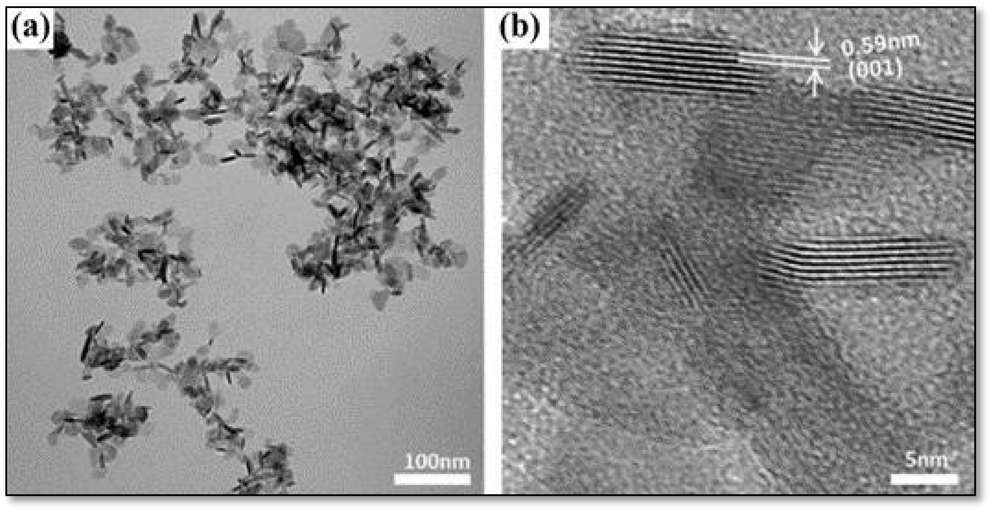
- Wang, X.; Xie, Y.; Bateer, B.; Pan, K.; Zhou, Y.; Zhang, Y.; Wang, G.; Zhou, W.; Fu, H. Hexagonal FeS nanosheets with high-energy (001) facets: Counter electrode materials superior to platinum for dye-sensitized solar cells. Nano Res. 2016, 9, 2862–2874. [Google Scholar] [CrossRef]
- Al-Janabi, A.S.; Hussin, M.; Abdullah, M. Stability, thermal conductivity and rheological properties of graphene and MWCNT in nanolubricant using additive surfactants. Case Stud. Therm. Eng. 2021, 28, 101607. [Google Scholar] [CrossRef]
- Shombe, G.B.; Khan, M.D.; Zequine, C.; Zhao, C.; Gupta, R.K.; Revaprasadu, N. Direct solvent free synthesis of bare α-NiS, β-NiS and α-β-NiS composite as excellent electrocatalysts: Effect of self-capping on supercapacitance and overall water splitting activity. Sci. Rep. 2020, 10, 3260. [Google Scholar] [CrossRef] [Green Version]
- Tang, Z.; Yang, H. Transition Metal Chalcogenides for Energy Storage and Conversion; Elsevier Inc.: Amsterdam, The Netherlands, 2019. [Google Scholar] [CrossRef]
- Lynch, B.B.; Kelliher, A.P.; Anderson, B.D.; Japit, A.; Spencer, M.A.; Rizvi, M.H.; Sarac, M.F.; Augustyn, V.; Tracy, J.B. Sulfidation and selenidation of nickel nanoparticles. Carbon Energy 2021, 3, 582–589. [Google Scholar] [CrossRef]
- Gao, M.R.; Jiang, J.; Yu, S.H. Solution-based synthesis and design of late transition metal chalcogenide materials for oxygen reduction reaction (ORR). Small 2012, 8, 13–27. [Google Scholar] [CrossRef] [PubMed]
- Kershaw, S.V.; Susha, A.S.; Rogach, A.L. Narrow bandgap colloidal metal chalcogenide quantum dots: Synthetic methods, heterostructures, assemblies, electronic and infrared optical properties. Chem. Soc. Rev. 2013, 42, 3033–3087. [Google Scholar] [CrossRef]
- Popoola, K.; Gondal, M.A.; AlGhamdi, J.M.; Qahtan, T.F. Photofabrication of Highly Transparent Platinum Counter Electrodes at Ambient Temperature for Bifacial Dye Sensitized Solar Cells. Sci. Rep. 2018, 8, 12864. [Google Scholar] [CrossRef] [PubMed] [Green Version]
- Zhou, R.; Guo, W.; Yu, R.; Pan, C. Highly flexible, conductive and catalytic Pt networks as transparent counter electrodes for wearable dye-sensitized solar cells. J. Mater. Chem. A 2015, 3, 23028–23034. [Google Scholar] [CrossRef]
- Mustafa, M.N.; Shafie, S.; Zainal, Z.; Sulaiman, Y. A Novel Poly(3,4-ethylenedioxythiophene)-graphene Oxide/Titanium Dioxide Composites Counter Electrode for Dye-Sensitized Solar Cell. J. Nanomater. 2017, 2017, 4045672. [Google Scholar] [CrossRef] [Green Version]
- Hessein, A.; Wang, F.; Masai, H.; Matsuda, K.; El-Moneim, A.A. Improving the stability of CdS quantum dot sensitized solar cell using highly efficient and porous CuS counter electrode. J. Renew. Sustain. Energy 2017, 9, 023504. [Google Scholar] [CrossRef]
- Gao, C.; Han, Q.; Wu, M. Review on transition metal compounds based counter electrode for dye-sensitized solar cells. J. Energy Chem. 2018, 27, 703–712. [Google Scholar] [CrossRef] [Green Version]
- Indhumathy, M.; Prakasam, A. Controllable Synthesis of NiS/rGO Hybrid Composite: An Excellent Counter Electrode for Dye Sensitized Solar Cell. J. Clust. Sci. 2019, 31, 91–98. [Google Scholar] [CrossRef]
- Durga, K.; Rao, S.S.; Reddy, A.E.; Gopi, C.V.V.M.; Kim, H.J. Achieving copper sulfide leaf like nanostructure electrode for high performance supercapacitor and quantum-dot sensitized solar cells. Appl. Surf. Sci. 2018, 435, 666–675. [Google Scholar] [CrossRef]
- Chen, M.; Shao, L.L. Review on the recent progress of carbon counter electrodes for dye-sensitized solar cells. Chem. Eng. J. 2016, 304, 629–645. [Google Scholar] [CrossRef]
- Zhang, H.; Ji, X.; Liu, N.; Zhao, Q. Synergy effect of carbon nanotube and graphene hydrogel on highly efficient quantum dot sensitized solar cells. Electrochim. Acta 2019, 327, 134937. [Google Scholar] [CrossRef]
- Wu, C.S.; Chang, T.W.; Teng, H.; Lee, Y.L. High performance carbon black counter electrodes for dye-sensitized solar cells. Energy 2016, 115, 513–518. [Google Scholar] [CrossRef]
- Zou, X.; Zhang, Y. Noble metal-free hydrogen evolution catalysts for water splitting. Chem. Soc. Rev. 2015, 44, 5148–5180. [Google Scholar] [CrossRef]
- Alvarez-Galvan, M.C.; Campos-Martin, J.M.; Fierro, J.L.G. Transition metal phosphides for the catalytic hydrodeoxygenation of waste oils into green diesel. Catalysts 2019, 9, 293. [Google Scholar] [CrossRef] [Green Version]
- Liu, Z.; Liu, H.; Gu, X.; Feng, L. Oxygen evolution reaction efficiently catalyzed by a quasi-single-crystalline cobalt fluoride. Chem. Eng. J. 2020, 397, 125500. [Google Scholar] [CrossRef]
- Khan, Y.; Sadia, H.; Ali Shah, S.Z.; Khan, M.N.; Shah, A.A.; Ullah, N.; Ullah, M.F.; Bibi, H.; Bafakeeh, O.T.; Khedher, N.B.; et al. Classification, synthetic, and characterization approaches to nanoparticles, and their applications in various fields of nanotechnology: A review. Catalysts 2022, 12, 1386. [Google Scholar] [CrossRef]
- Hussein, K. Applications of nanotechnology in renewable energies—A comprehensive overview and understanding. Renew. Sustain. Energy Rev. 2015, 42, 460–476. [Google Scholar] [CrossRef]
- Mao, S.S.; Shen, S.; Guo, L. Nanomaterials for renewable hydrogen production, storage and utilization. Prog. Nat. Sci. Mater. Int. 2012, 22, 522–534. [Google Scholar] [CrossRef] [Green Version]
- Serrano, E.; Rus, G.; García-Martínez, J. Nanotechnology for sustainable energy. Renew. Sustain. Energy Rev. 2009, 13, 2373–2384. [Google Scholar] [CrossRef]
- Notarianni, M.; Liu, J.; Vernon, K.; Motta, N. Synthesis and applications of carbon nanomaterials for energy generation and storage. Beilstein J. Nanotechnol. 2016, 7, 149–196. [Google Scholar] [CrossRef] [PubMed] [Green Version]
- Kulkarni, P.; Nataraj, S.K.; Balakrishna, R.G.; Nagaraju, D.H.; Reddy, M.V. Nanostructured binary and ternary metal sulfides: Synthesis methods and their application in energy conversion and storage devices. J. Mater. Chem. A 2017, 5, 22040–22094. [Google Scholar] [CrossRef]
- Al-Enizi, M.; Nafady, A.; El-Halwany, M.M.; Brooks, R.M.; Abutaleb, A.; Yousef, A. Electrospun carbon nanofiber-encapsulated NiS nanoparticles as an efficient catalyst for hydrogen production from hydrolysis of sodium borohydride. Int. J. Hydrogen Energy 2019, 44, 21716–21725. [Google Scholar] [CrossRef]
- Fadil, N.A.; Saravanan, G.; Ramesh, G.V.; Matsumoto, F.; Yoshikawa, H.; Ueda, S.; Tanabe, T.; Hara, T.; Ishihara, S.; Murakami, H.; et al. Synthesis and electrocatalytic performance of atomically ordered nickel carbide (Ni3C) nanoparticles. Chem. Commun. 2014, 50, 6451–6453. [Google Scholar] [CrossRef]
- Wang, M.; Anghel, A.M.; Marsan, B.; Ha, N.-L.C.; Pootrakulchote, N.; Zakeeruddin, S.M.; Grätzel, M. CoS supersedes Pt as efficient electrocatalyst for triiodide reduction in dye-sensitized solar cells. J. Am. Chem. Soc. 2009, 131, 15976–15977. [Google Scholar] [CrossRef]
- Jiang, W.; Li, G.R.; Gao, X.P. Erratum: (Highly ordered TiN nanotube arrays as counter electrodes for dye-sensitized solar cells. Chem. Commun. 2009, 44, 6720–6722. [Google Scholar] [CrossRef]
- Quy, V.H.V.; Park, J.H.; Kang, S.H.; Kim, H.; Ahn, K.S. Improved electrocatalytic activity of electrodeposited Ni3S4 counter electrodes for dye- and quantum dot-sensitized solar cells. J. Ind. Eng. Chem. 2019, 70, 322–329. [Google Scholar] [CrossRef]
- Sun, H.; Qin, D.; Huang, S.; Guo, X.; Li, D.; Luo, Y.; Meng, Q. Dye-sensitized solar cells with NiS counter electrodes electrodeposited by a potential reversal technique. Energy Environ. Sci. 2011, 4, 2630–2637. [Google Scholar] [CrossRef]
- Zhang, Q.; Mei, L.; Cao, X.; Tang, Y.; Zeng, Z. Intercalation and exfoliation chemistries of transition metal dichalcogenides. J. Mater. Chem. A 2020, 8, 15417–15444. [Google Scholar] [CrossRef]
- Zhao, P.; Feng, X.; Huang, D.; Yang, G.; Astruc, D. Basic concepts and recent advances in nitrophenol reduction by gold- and other transition metal nanoparticles. Coord. Chem. Rev. 2015, 287, 114–136. [Google Scholar] [CrossRef]
- Theerthagiri, J.; Senthil, R.A.; Nithyadharseni, P.; Lee, S.J.; Durai, G.; Kuppusami, P.; Madhavan, J.; Choi, M.Y. Recent progress and emerging challenges of transition metal sulfides based composite electrodes for electrochemical supercapacitive energy storage. Ceram. Int. 2020, 46, 14317–14345. [Google Scholar] [CrossRef]
- Patil, S.A.; Mengal, N.; Memon, A.A.; Jeong, S.H.; Kim, H.-S. CuS thin film grown using the one pot, solution-process method for dye-sensitized solar cell applications. J. Alloys Compd. 2017, 708, 568–574. [Google Scholar] [CrossRef]
- Yue, G.; Lin, J.Y.; Tai, S.Y.; Xiao, Y.; Wu, J. A catalytic composite film of MoS2/graphene flake as a counter electrode for Pt-free dye-sensitized solar cells. Electrochim. Acta 2012, 85, 162–168. [Google Scholar] [CrossRef]
- Khoo, S.Y.; Miao, J.; Yang, H.B.; He, Z.; Leong, K.C.; Liu, B.; Tan, T.T.Y. One-Step Hydrothermal Tailoring of NiCo2S4 Nanostructures on Conducting Oxide Substrates as an Efficient Counter Electrode in Dye-Sensitized Solar Cells. Adv. Mater. Interfaces 2015, 2, 2–10. [Google Scholar] [CrossRef]
- Zhang, Y.; Peng, Z.; Guan, S.; Fu, X. Novel Β-NiS film modified CdS nanoflowers heterostructure nanocomposite: Extraordinarily highly efficient photocatalysts for hydrogen evolution. Appl. Catal. B Environ. 2018, 224, 1000–1008. [Google Scholar] [CrossRef]
- Xu, J.; Zhang, L.; Xu, G.; Sun, Z.; Zhang, C.; Ma, X.; Qi, C.; Zhang, L.; Jia, D. Facile synthesis of NiS anchored carbon nanofibers for high-performance supercapacitors. Appl. Surf. Sci. 2018, 434, 112–119. [Google Scholar] [CrossRef]
- Yan, X.; Tong, X.; Ma, L.; Tian, Y.; Cai, Y.; Gong, C.; Zhang, M.; Liang, L. Synthesis of porous NiS nanoflake arrays by ion exchange reaction from NiO and their high performance supercapacitor properties. Mater. Lett. 2014, 124, 133–136. [Google Scholar] [CrossRef]
- Muthu, N.S.; Gopalan, M. Polyethylene glycol-assisted growth of Ni3S4 closely packed nanosheets on Ni-foam for enhanced supercapacitor device. J. Solid State Electrochem. 2019, 23, 2937–2950. [Google Scholar] [CrossRef]
- He, H.; Chen, C.; Chen, Z.; Li, P.; Ding, S. Ni3S2 @ S-carbon nanotubes synthesized using NiS2 as sulfur source and precursor for high performance sodium-ion half/full cells. Sci. China Mater. 2019, 63, 216–228. [Google Scholar] [CrossRef] [Green Version]
- Parveen, N.; Ansari, S.G.A.; Ansari, S.G.A.; Fouad, H.; El-Salam, N.M.A.; Cho, M.H. Solid-state symmetrical supercapacitor based on hierarchical flower-like nickel sulfide with shape-controlled morphological evolution. Electrochim. Acta 2018, 268, 82–93. [Google Scholar] [CrossRef]
- Jeevanandam, J.; Barhoum, A.; Chan, Y.S.; Dufresne, A.; Danquah, M.K. Review on nanoparticles and nanostructured materials: History, sources, toxicity and regulations. Beilstein J. Nanotechnol. 2018, 9, 1050–1074. [Google Scholar] [CrossRef] [PubMed] [Green Version]
- Zhang, X.; Cheng, X.; Zhang, Q. Nanostructured energy materials for electrochemical energy conversion and storage: A review. J. Energy Chem. 2016, 25, 967–984. [Google Scholar] [CrossRef]
- Mourdikoudis, S.; Pallares, R.M.; Thanh, N.T.K. Characterization techniques for nanoparticles: Comparison and complementarity upon studying nanoparticle properties. Nanoscale 2018, 10, 12871–12934. [Google Scholar] [CrossRef] [PubMed] [Green Version]
- Wu, M.; Wang, Y.; Lin, X.; Yu, N.; Wang, L.; Wang, L.; Hagfeldtc, A.; Ma, T. Economical and effective sulfide catalysts for dye-sensitized solar cells as counter electrodes. Phys. Chem. Chem. Phys. 2011, 13, 19298–19301. [Google Scholar] [CrossRef] [PubMed]
- He, Q.; Huang, S.; Zai, J.; Tang, N.; Li, B.; Qiao, Q.; Qian, X. Efficient Counter Electrode Manufactured from Ag2S Nanocrystal Ink for Dye-Sensitized Solar Cells. Chem. A Eur. J. 2015, 21, 15153–15157. [Google Scholar] [CrossRef]
- Zhang, X.; Guo, W.; Pan, C. Transparent conducting oxide-free and Pt-free flexible dye-sensitized solar cells employing CuS-nanosheet networks as counter electrodes. J. Mater. Chem. A 2016, 4, 6569–6576. [Google Scholar] [CrossRef]
- Sun, P.; Yao, F.; Ban, X.; Huang, N.; Sun, X. Directly hydrothermal growth of antimony sulfide on conductive substrate as efficient counter electrode for dye-sensitized solar cells. Electrochim. Acta 2015, 174, 127–132. [Google Scholar] [CrossRef]
- Yue, G.; Liu, X.; Mao, Y.; Zheng, H.; Zhang, W. A promising hybrid counter electrode of vanadium sulfide decorated with carbon nanotubes for efficient dye-sensitized solar cells. Mater. Today Energy 2017, 4, 58–65. [Google Scholar] [CrossRef]
- Bai, Y.; Zong, X.; Yu, H.; Chen, Z.G.; Wang, L. Scalable low-cost SnS2 nanosheets as counter electrode building blocks for dye-sensitized solar cells. Chem. A Eur. J. 2014, 20, 8670–8676. [Google Scholar] [CrossRef]
- Yang, B.; Zuo, X.; Xiao, H.; Zhou, L.; Yang, X.; Li, G.; Wu, M.; Ma, Y.; Jin, S.; Chen, X. SnS2 as low-cost counter-electrode materials for dye-sensitized solar cells. Mater. Lett. 2014, 133, 197–199. [Google Scholar] [CrossRef]
- Hu, Z.; Xia, K.; Zhang, J.; Hu, Z.; Zhu, Y. In situ growth of novel laminar-shaped Co3S4 as an efficient counter electrode for dye-sensitized solar cells. RSC Adv. 2014, 4, 42917–42923. [Google Scholar] [CrossRef]
- Jin, J.; Zhang, X.; He, T. Self-assembled CoS2 nanocrystal film as an efficient counter electrode for dye-sensitized solar cells. J. Phys. Chem. C 2014, 118, 24877–24883. [Google Scholar] [CrossRef]
- Huo, J.; Zheng, M.; Tu, Y.; Wu, J.; Hu, L.; Dai, S. A high performance cobalt sulfide counter electrode for dye-sensitized solar cells. Electrochim. Acta 2015, 159, 166–173. [Google Scholar] [CrossRef]
- Shukla, S.; Loc, N.H.; Boix, P.P.; Koh, T.M.; Prabhakar, R.R.; Mulmudi, H.K.; Zhang, J.; Chen, S.; Ng, C.F.; Huan, C.H.A.; et al. Iron pyrite thin film counter electrodes for dye-sensitized solar cells: High efficiency for iodine and cobalt redox electrolyte cells. ACS Nano 2014, 8, 10597–10605. [Google Scholar] [CrossRef]
- Zhang, C.; Deng, L.; Zhang, P.; Ren, X.; Li, Y.; He, T. Electrospun FeS nanorods with enhanced stability as counter electrodes for dye-sensitized solar cells. Electrochim. Acta 2017, 229, 229–238. [Google Scholar] [CrossRef]
- Raj, S.I.; Xu, X.; Yang, W.; Yang, F.; Hou, L.; Li, Y. Highly active and reflective MoS2 counter electrode for enhancement of photovoltaic efficiency of dye sensitized solar cells. Electrochim. Acta 2016, 212, 614–620. [Google Scholar] [CrossRef]
- Huang, N.; Li, G.; Xia, Z.; Zheng, F.; Huang, H.; Li, W.; Xiang, C.; Sun, Y.; Sun, P.; Sun, X. Solution-processed relatively pure MoS2 nanoparticles in-situ grown on graphite paper as an efficient FTO-free counter electrode for dye-sensitized solar cells. Electrochim. Acta 2017, 235, 182–190. [Google Scholar] [CrossRef]
- Jeong, H.; Kim, J.Y.; Koo, B.; Son, H.J.; Kim, D.; Ko, M.J. Rapid sintering of MoS2 counter electrode using near-infrared pulsed laser for use in highly efficient dye-sensitized solar cells. J. Power Sources 2016, 330, 104–110. [Google Scholar] [CrossRef]
- Zhang, J.; Najmaei, S.; Lin, H.; Lou, J. MoS2 atomic layers with artificial active edge sites as transparent counter electrodes for improved performance of dye-sensitized solar cells. Nanoscale 2014, 6, 5279–5283. [Google Scholar] [CrossRef] [PubMed]
- Li, Y.; Chang, Y.; Zhao, Y.; Wang, J.; Wang, C.W. In situ synthesis of oriented NiS nanotube arrays on FTO as high-performance counter electrode for dye-sensitized solar cells. J. Alloys Compd. 2016, 679, 384–390. [Google Scholar] [CrossRef]
- Wan, Z.; Jia, C.; Wang, Y. In situ growth of hierarchical NiS2 hollow microspheres as efficient counter electrode for dye-sensitized solar cell. Nanoscale 2015, 7, 12737–12742. [Google Scholar] [CrossRef]
- Yang, X.; Luo, J.; Zhou, L.; Yang, B.; Zuo, X.; Li, G.; Tang, H.; Zhang, H.; Wu, M.; Ma, Y.; et al. A novel Pt-free counter electrode for dye-sensitized solar cells: Nickel sulfide hollow spheres. Mater. Lett. 2014, 136, 241–244. [Google Scholar] [CrossRef]
- Savariraj, A.D.; Rajendrakumar, G.; Selvam, S.; Karthick, S.N.; Balamuralitharan, B.; Kim, H.-J.; Viswanathan, K.K.; Vijayakumarc, M.; Prabakar, K. Stacked Cu1.8S nanoplatelets as counter electrode for quantum dot-sensitized solar cell. RSC Adv. 2015, 5, 100560–100567. [Google Scholar] [CrossRef] [Green Version]
- Yuan, B.; Duan, L.; Gao, Q.; Zhang, X.; Li, X.; Yang, Y.; Chen, L.; Lü, W. Investigation of metal sulfide composites as counter electrodes for improved performance of quantum dot sensitized solar cells. Mater. Res. Bull. 2018, 100, 198–205. [Google Scholar] [CrossRef]
- Quy, V.H.V.; Vijayakumar, E.; Ho, P.; Park, J.-H.; Rajesh, J.A.; Kwon, J.; Chae, J.; Kim, J.-H.; Kang, S.-H.; Ahn, K.-S. Electrodeposited MoS2 as electrocatalytic counter electrode for quantum dot- and dye-sensitized solar cells. Electrochim. Acta 2018, 260, 716–725. [Google Scholar] [CrossRef]
- Vijayakumar, E.; Kang, S.-H.; Ahn, K.-S. Facile Electrochemical Synthesis of Manganese Cobalt Sulfide Counter Electrode for Quantum Dot-Sensitized Solar Cells. J. Electrochem. Soc. 2018, 165, F375–F380. [Google Scholar] [CrossRef]
- Li, W.; He, L.; Zhang, J.; Li, B.; Chen, Q.; Zhong, Q. Anchoring Spinel MnCo2S4 on Carbon Nanotubes as Efficient Counter Electrodes for Quantum Dot Sensitized Solar Cells. J. Phys. Chem. C 2019, 123, 21866–21873. [Google Scholar] [CrossRef]
- Kusuma, J.; Akash, S.; Balakrishna, R.G. Transition metal nanohybrid as efficient and stable counter electrode for heterostructure quantum dot sensitized solar cells: A trial. Sol. Energy 2020, 201, 674–681. [Google Scholar] [CrossRef]
- Tian, Z.; Chen, Q.; Zhong, Q. Honeycomb spherical 1T-MoS2 as efficient counter electrodes for quantum dot sensitized solar cells. Chem. Eng. J. 2020, 396, 125374. [Google Scholar] [CrossRef]


| TMS Based CE | Synthesis and Deposition Method | PCE Performance (%) | FF | Voc (V) | Jsc (mA cm−2) | Electrolyte | Comments on PV Performance of DSSCs with Different TMS-Based CEs | Ref. | ||||
|---|---|---|---|---|---|---|---|---|---|---|---|---|
| TMS-Based CE | Pt Based CE | TMS-Based CE | Pt Based CE | TMS-Based CE | Pt Based CE | TMS-Based CE | Pt Based CE | |||||
| WS2 | Simple chemical method | 7.73 | 7.64 | 0.70 | 0.66 | 0.78 | 0.78 | 14.13 | 14.89 | I−/I3− redox-couples | Comparable PCEs for DSSCs with WS2, MoS2, and platinized CEs | [107] |
| MoS2 | 7.59 | 7.64 | 0.73 | 0.66 | 0.76 | 0.78 | 13.84 | 14.89 | ||||
| Ag2S nanoparticles (NPs) | Colloidal synthesis process | 8.40 | 8.11 | 0.66 | 0.64 | 0.757 | 0.758 | 16.79 | 16.73 | I−/I3− redox-couple | Higher PCE for DSSC with Ag2S NPs CE in comparison to that with platinized CE | [108] |
| CuS nanosheet (NS) | Electrospinning | 6.38 | 5.60 | 0.534 | 0.506 | 0.66 | 0.70 | 18.10 | 15.81 | I−/I3− redox-couple | Higher PCE for DSSC with CuS NS CE in comparison to DSSC with Pt CE | [109] |
| Sb2S3 film | Hydrothermal and post-annealing treatments | 5.37 | 5.36 | 0.528 | 0.653 | 0.70 | 0.65 | 14.5 | 12.5 | I−/I3− redox-couple | Associated PCE of DSSC with Sb2S3 CE was higher than Pt CE | [110] |
| CNTs/VS2 | Hydrothermal method | 8.02 | 6.49 | 0.682 | 0.645 | 0.755 | 0.717 | 15.57 | 14.03 | I−/I3− redox-couple | DSSC with CNTs/VS2 CE showed higher conductivity, better electrocatalytic activity, and higher PCE compared with Pt CE | [111] |
| SnS2 nanosheet (NS) | Solution-processed approach | 7.64 | 7.71 | 0.607 | 0.639 | 0.743 | 0.730 | 16.96 | 16.53 | I−/I3− redox-couple | An increase in PCE was recorded from 7.64% (DSSC with SnS2 NS CE) to 8.06% for DSSC with SnS2 NS + CNPs CE | [112] |
| SnS2 NS + carbon nanoparticles (CNPs) | Solution-based approach | 8.06 | 7.71 | 0.619 | 0.639 | 0.745 | 0.730 | 17.47 | 16.53 | |||
| SnS2 NPs | Hydrothermal method | 6.30 | 6.67 | 0.53 | 0.59 | 0.759 | 0.783 | 15.66 | 15.53 | I−/I3− redox-couple | PCEs were comparable to the DSSCs, given the closeness of associated values | [113] |
| Co3S4 NSs | Hydrothermal method | 7.19 | 7.27 | 0.66 | 0.67 | 0.70 | 0.70 | 15.34 | 15.99 | I−/I3− redox-couple | DSSC with Co3S4 NSs CE indicated comparable PCE to platinized CE | [114] |
| CoS2 nanocrystals | Hydrothermal method | 6.78 | 7.38 | 0.64 | 0.68 | 0.71 | 0.72 | 14.62 | 14.78 | I−/I3− redox-couple | DSSC with CoS2 CE exhibited PCE comparable to Pt CE | [115] |
| CoS film | Electrophoretic deposition and ion exchange deposition | 7.72 | 7.18 | 0.618 | 0.718 | 0.757 | 0.792 | 16.50 | 12.63 | I−/I3− redox-couple | PCEs of the DSSCs with CoS film and Pt CEs were relatively comparable, given the low cost of CoS film, would be more suitable for application | [116] |
| FeS-HEF | Solution-phase chemical method | 8.88 | 7.73 | 0.66 | 0.65 | 0.72 | 0.75 | 18.81 | 15.79 | I−/I3− redox-couple | DSSC with FeS-HEF CE demonstrated excellent electrocatalytic activity and produced PCE higher than Pt CE | [60] |
| FeS2 film | Spray pyrolysis | 7.97 | 7.54 | 0.65 | 0.66 | 0.79 | 0.78 | 15.20 | 14.77 | I−/I3− redox-couple | FeS2 CE associated PCE was higher than PCE (Pt) of 7.54% with the use of I−/I3− redox couples | [117] |
| FeS nanorods (NRs) (FeS NRs) | Electrospinning | 6.47 | 7.05 | 0.63 | 0.62 | 0.667 | 0.714 | 14.00 | 15.39 | I−/I3− redox couple | PCE of DSSC with FeS NRs CE was comparable to Pt CE | [118] |
| MoS2 | Chemical vapor deposition | 7.50 | 7.28 | 0.697 | 0.700 | 0.707 | 0.712 | 15.2 | 14.6 | I−/I3− redox couple | DSSC with MoS2 CE produced higher PCE in comparison to Pt CE, producing PCE of 7.28% | [119] |
| MoS2 with graphite paper (GP) as TCO | Solution-processed route | 6.48 | 6.22 | 0.698 | 0.675 | 0.696 | 0.720 | 13.34 | 12.79 | I−/I3− redox couple | DSSC with MoS2 CE outperformed Pt CE with PCE of 6.22% | [120] |
| MoS2 | Heat-sintering method with a near-infrared (IR) pulsed laser | 7.19 | 7.42 | 0.67 | 0.70 | 0.718 | 0741 | 14.94 | 14.30 | I−/I3− redox couple | DSSC with laser-sintered MoS2 CE exhibited good electrocatalytic performance, with its PCE comparable to DSSC with Pt CE | [121] |
| MoS2 film | Solid state sulfurization method | 5.80 | 7.30 | 0.52 | 0.66 | 0.73 | 0.72 | 15.20 | 15.40 | I−/I3− redox couple | PCE of DSSC with patterned MoS2 CE was lower but comparable to Pt CE | [122] |
| NiS NTs | Electrochemical deposition | 9.80 | 8.50 | 0.73 | 0.72 | 0.738 | 0.737 | 18.40 | 15.90 | I−/I3− redox couple | DSSC with NiS NTs CE demonstrated both excellent electrocatalytic activity towards I3– reduction and high electrochemical stability, resulting in higher PCE | [123] |
| NiS2 hierarchical hollow microspheres | Hydrothermal method | 7.84 | 7.89 | 0.63 | 0.62 | 0.712 | 0.747 | 17.48 | 17.04 | I−/I3− redox couple | DSSC with NiS2 CE demonstrated excellent electrochemical catalytic activity, and associated PCE was comparable to Pt CE | [124] |
| NiS hollow spheres | Hydrothermal method | 6.90 | 6.75 | 0.637 | 0.621 | 0.71 | 0.72 | 15.26 | 15.11 | I−/I3− redox couple | DSSC with hollow NiS sphere CE exhibited better electrochemical catalytic activity, as confirmed by its higher PCE | [125] |
| TMS Based CE | Synthesis and Deposition Method | PCE Performance (%) | FF | Voc (V) | Jsc (mA cm−2) | Electrolyte | Comments on PV Performance of QDSSCs with Different TMS-Based CEs | Ref. | ||||
|---|---|---|---|---|---|---|---|---|---|---|---|---|
| TMS-Based CE | Pt-Based CE | TMS-Based CE | Pt Based CE | TMS-Based CE | Pt Based CE | TMS-Based CE | Pt Based CE | |||||
| Cu1.8S nanoplates | Chemical bath deposition method | 5.16 | 1.19 | 0.451 | 0.317 | 0.60 | 0.56 | 19.10 | 6.70 | S−2/Sx− redox-couple | QDSSC with Cu1.8S nanoplates CE exhibited the best photoconversion behavior in comparison with platinized CE | [126] |
| CoS leaf-like nanostructure | Solution-based approach | 3.48 | - | 0.529 | - | 0.57 | - | 11.54 | - | S−2/Sx− redox-couple | 72.41% increase in PCE of QDSSC resulting from a 2 to 3 h heat treatment process of CoS leaf-like nanostructure | [73] |
| CoS/CuS | CEs were deposited onto FTO substrates by chemical bath deposition (CBD) | 5.22 | - | 0.47 | - | 0.56 | - | 19.96 | - | S−2/Sx− redox-couple | The utilization of different TMSs and their composites as CEs indicated the variation of PCEs for QDSSCs from 1.62 to 5.22% | [127] |
| CuS | 4.73 | - | 0.45 | - | 0.58 | - | 17.82 | - | ||||
| CuS/NiS | 2.56 | - | 0.44 | - | 0.45 | - | 13.09 | - | ||||
| CoS | 2.23 | - | 0.43 | - | 0.42 | - | 12.39 | - | ||||
| NiS | 1.62 | - | 0.40 | - | 0.42 | - | 9.52 | - | ||||
| MoS2 | CE was deposited onto the FTO substrate by potentiostatic electrodeposition | 3.69 | 2.16 | 0.527 | 0.339 | 0.51 | 0.55 | 13.86 | 11.6 | S−2/Sx− redox-couple | QDSSC with MoS2 CE exhibited a much higher PCE than platinized CE | [128] |
| Ni3S4 film | Potentiodynamic electrodeposition | 4.57 | 2.56 | 0.526 | 0.328 | 0.545 | 0.555 | 15.92 | 14.07 | S−2/Sx− redox-couple | QDSSC with Ni3S4 film CE exhibited better photoconversion behavior in comparison to Pt CE | [90] |
| Manganese cobalt sulfide (MCS) thin film | Electrochemical Synthesis, CE was deposited on FTO by CBD | 3.22 | 1.08 | 0.51 | 0.28 | 0.50 | 0.41 | 12.62 | 9.28 | S−2/Sx− redox-couple | QDSSC with Pt CE resulted in poor FF and much lower PCE of 1.08% in comparison to MCS thin film CE | [129] |
| Ternary spinel MnCo2S4 | Ionic exchange deposition, CEs were deposited onto FTO substrates by drop-coating. | 2.98 | - | 0.40 | - | 0.46 | - | 16.20 | - | S−2/Sx− redox-couple | An improvement in PCE was identified with the utilization of MnCo2S4/CNT as CE in QDSSC | [130] |
| Carbon nanotubes (CNTS)/MnCo2S4 | 4.85 | - | 0.45 | - | 0.58 | - | 18.45 | - | ||||
| MoS2/CuS nanohybrid | Hydrothermal method | 6.70 | - | 0.412 | - | 0.62 | - | 26.25 | - | S−2/Sx− redox-couple | Reported values demonstrated good PV performance and were based on the statistical average of six cells | [131] |
| Honeycomb spherical metallic 1T-MoS2 | Hydrothermal method | 6.03 | - | 0.56 | - | 0.607 | - | 17.63 | - | S−2/Sx− redox-couple | QDSSC with 1T-MoS2 CE demonstrated good photo conversion efficiency supported by associated parametric values | [132] |
Disclaimer/Publisher’s Note: The statements, opinions and data contained in all publications are solely those of the individual author(s) and contributor(s) and not of MDPI and/or the editor(s). MDPI and/or the editor(s) disclaim responsibility for any injury to people or property resulting from any ideas, methods, instructions or products referred to in the content. |
© 2023 by the authors. Licensee MDPI, Basel, Switzerland. This article is an open access article distributed under the terms and conditions of the Creative Commons Attribution (CC BY) license (https://creativecommons.org/licenses/by/4.0/).
Share and Cite
Kharboot, L.H.; Fadil, N.A.; Bakar, T.A.A.; Najib, A.S.M.; Nordin, N.H.; Ghazali, H. A Review of Transition Metal Sulfides as Counter Electrodes for Dye-Sensitized and Quantum Dot-Sensitized Solar Cells. Materials 2023, 16, 2881. https://doi.org/10.3390/ma16072881
Kharboot LH, Fadil NA, Bakar TAA, Najib ASM, Nordin NH, Ghazali H. A Review of Transition Metal Sulfides as Counter Electrodes for Dye-Sensitized and Quantum Dot-Sensitized Solar Cells. Materials. 2023; 16(7):2881. https://doi.org/10.3390/ma16072881
Chicago/Turabian StyleKharboot, Layla Haythoor, Nor Akmal Fadil, Tuty Asma Abu Bakar, Abdillah Sani Mohd Najib, Norhuda Hidayah Nordin, and Habibah Ghazali. 2023. "A Review of Transition Metal Sulfides as Counter Electrodes for Dye-Sensitized and Quantum Dot-Sensitized Solar Cells" Materials 16, no. 7: 2881. https://doi.org/10.3390/ma16072881