Article

Ultra-High Sensitivity and Temperature-Insensitive Optical Fiber Strain Sensor Based on Dual Air Cavities

1
College of Physics and Electronic Science, Hubei Normal University, Huangshi 435002, China
2
Institute for Advanced Materials, Hubei Normal University, Huangshi 435002, China
3
Laboratory of Solid-State Microstructures, Nanjing University, Nanjing 210093, China
*
Author to whom correspondence should be addressed.
Materials 2023, 16(8), 3165; https://doi.org/10.3390/ma16083165
Submission received: 28 February 2023 / Revised: 30 March 2023 / Accepted: 16 April 2023 / Published: 17 April 2023
(This article belongs to the Section Optical and Photonic Materials)

Abstract

:
This study proposed an all-fiber Fabry–Perot interferometer (FPI) strain sensor with two miniature bubble cavities. The device was fabricated by writing two axial, mutually close short-line structures via femtosecond laser pulse illumination to induce a refractive index modified area in the core of a single-mode fiber (SMF). Subsequently, the gap between the two short lines was discharged with a fusion splicer, resulting in the formation of two adjacent bubbles simultaneously in a standard SMF. When measured directly, the strain sensitivity of dual air cavities is 2.4 pm/με, the same as that of a single bubble. The measurement range for a single bubble is 802.14 µε, while the measurement range for a double bubble is 1734.15 µε. Analysis of the envelope shows that the device possesses a strain sensitivity of up to 32.3 pm/με, which is 13.5 times higher than that of a single air cavity. Moreover, with a maximum temperature sensitivity of only 0.91 pm/°C, the temperature cross sensitivity could be neglected. As the device is based on the internal structure inside the optical fiber, its robustness could be guarantee. The device is simple to prepare, highly sensitive, and has wide application prospects in the field of strain measurement.

1. Introduction

Fiber optic sensors have been employed in a wide range of applications, including the measurement of several physical quantities such as pressure [1,2,3], salt content [4,5], vibration [6,7,8], refractive index [9,10,11], temperature [12,13,14], strain [15,16], micro-displacement [17], and relative humidity [18]. Owing to their advantages, such as compact size, light weight, immunity to electromagnetic interference, high sensitivity, wide temperature range, stability, and durability, optical fiber sensors play a pivotal role in the industry. In particular, strain measurement is an extensively used fiber optic sensing technology because of its ability to perform medical monitoring and civil engineering. Recently, Mach–Zehnder interferometers [19,20] (MZIs), long-period gratings [21] (LPGs), and particularly fiber Bragg gratings [22,23] (FBGs), have garnered attention in the field of strain-sensing technology; however, none of them exhibit low temperature sensitivity, which increases the cross-sensitivity between temperature and strain. Consequently, temperature compensation devices inevitably increase the cost and complicate the overall system. In contrast, strain sensors based on fiber optic Fabry–Perot interferometers (FPIs) can obtain extremely low temperature cross-sensitivity, as tiny air cavities created in the fiber exhibit a small thermal expansion coefficient, where splicing techniques are used to fabricate fiber optic FPI sensors. Certain methods employed are hollow-core photonic crystal fiber splicing with single-mode fiber [24,25], capillary splicing with single-mode fiber [26,27], and two single-mode fibers dipped in liquid for splicing [28]. Owing to the large Young’s modulus of optical fiber materials, the strain sensitivity of these sensors can be limited to typically only a few pm/µε. In general, the strain sensitivity of fiber optic sensors is increased at the expense of its robustness, for instance, tapered fibers or microfibers [29,30], which have a relatively small measurement range. Therefore, the investigation of sensors that are simultaneously insensitive to temperature and can increase strain sensitivity while not reducing the measurement range are of significance. Furthermore, whether the splicing process can be omitted remains a question worth exploring.
To simultaneously measure multiple parameters or to enhance measurement sensitivity, fiber optic sensors with a dual-cavity structure are commonly used. A dual-cavity fiber Fabry–Pérot interferometer (DCFFPI) has been proposed for the measurement of relative humidity and temperature [31]. Lee et al. proposed a novel configuration based on a DCFFPI that can simultaneously measure the thermo-optic coefficient (TOC) and thermal expansion coefficient (TEC) of a polymer [32]. Pullteap et al. proposed a method for automated fringe counting of a dual-cavity extrinsic fiber Fabry–Perot interferometer for vibration measurements [33]. A DCFFPI sensor has also been used to measure both temperature and pressure [34,35]. These sensors cascade a fiber-optic intrinsic Fabry–Perot interferometer (IFPI) and an extrinsic Fabry–Perot interferometer (EFPI). These two cavities were used to measure their different parameters.
This study proposed and demonstrated a novel all-fiber FPI strain sensor with two miniature bubble cavities fabricated without splicing. To the best of our knowledge, this is the first study to report the simultaneous increase in the strain sensitivity and measurement range. Moreover, as the temperature sensitivity of the proposed sensor was only 0.91 pm/°C, the temperature cross-sensitivity could be neglected. Thus, no temperature compensation was needed, which rendered the entire measurement system simple in nature. This device was fabricated by first writing two axial, mutually close short-line structures in the core of a single-mode fiber (SMF) by femtosecond laser direct writing. Subsequently, the gap between the two short lines was discharged using a fusion splicer, which concurrently produced two bubbles close to each other in a SMF. When measured directly, the strain sensitivity of dual air cavities was 2.4 pm/με (same as that of one bubble); however, the measurement range was doubled. Further, analysis of the envelope indicates that the device exhibits a strain sensitivity of up to 32.3 pm/με, which is 13.5 times higher than that of a single air cavity. The prepared device can be used as a promising strain sensor with desirable high sensitivity strain, a relatively large measurement range, and negligible temperature sensitivity.

2. Device Fabrication

Figure 1 shows the physical flow chart of the all-fiber FPI strain sensor fabrication system. A chirped pulse amplification laser system (Coherent Inc., Santa Clara, CA, USA) delivered 35 fs laser pulses with a repetition rate of 1 kHz at a central wavelength of 800 nm. The pulses were focused on the fiber core through an objective lens (100×, Olympus Corp., Shinjuku City, Tokyo) with a numerical aperture (NA) of 0.9. The femtosecond laser pulse energy was approximately 1.2 µJ, which was adjusted using a variable-density filter. The SMF (9 µm/125 µm, YOFC, Wuhan, China) was held horizontally by the clamp on a laser micromachining platform (Prior Scientific Instruments Ltd., Cambridge, UK), which exhibited a three-dimensional motion controlled by a computer, a resolution of 1 μm, as shown in Figure 1a.
There are two steps in the fabrication process:
  • As illustrated in Figure 1b, a 35 µm short-line structure is inscribed on the fiber core using a femtosecond laser pulse at a scanning speed of 10 µm/s. Each transverse short-line structure is written in just 3.5 s. The same procedure is used to inscribe two short-line structures on the fiber, each 35 µm long and 15 µm apart, as shown in Figure 1c. This process does not create a cavity; it merely modifies the fiber’s refractive index;
  • The area where the refractive index has been altered by direct writing with the femtosecond laser is observed using a laser pass-through pen. When the laser travels through the laser-etched zone, it experiences a relatively high insertion loss, producing a bright spot when the laser passes through it, as shown in Figure 1d. The fiber with only one horizontal short structure is placed in a fusion splicer and discharged against the splicer’s center to form an air cavity 95.35 µm wide, as demonstrated in Figure 1e. The first fiber optic sensor containing a single bubble was fabricated. Subsequently, the second fiber sensor with a double bubble is created by discharging a fiber fusion machine in the gap between two short structures, resulting in two air cavities close to each other in a standard SMF with widths of 82.37 µm and 91.28 µm and a spacing of about 21 µm between them, as shown in Figure 1f. Next, we compare the performance of single-bubble and double-bubble fiber sensors.
The device’s sensing length is less than 200 µm, indicating a particularly compact structure. A JILONG KL-300T fusion splicer was used, and the fusing current and duration were 10 mA and 1.5 s, respectively. It is important to note that once the femtosecond laser energy, the discharge current, and time of the fiber fusion machine have been determined, the microbubble parameters remain stable and reproducible. The microcavity is approximately 90 µm in size, and minor variations in its width have little effect on the strain sensitivity of the fiber optic sensor [28].

3. Operation Principle of the Device

The incident beam travels along the core of the SMF, and is reflected on both surfaces of the FP cavity, eventually recombining in the core to form interference fringes at the output. The intensity of the reflected beam at the two interfaces of a single FP cavity was set to I1 and I2, respectively, and the interference intensity could be expressed as follows.
I = I 1 + I 2 + 2 I 1 I 2 cos   ( 4 π n a i r L λ + ϕ 0 )
where 𝜆 is the wavelength of the propagation light, nair is the effective refractive index of the microcavity, L is the cavity length of the FPI, and 𝜙0 is the initial phase of the interference. The normalized signals intensity from individual FPI within the fiber can be simplified expression as follows:
I   ( L ) = cos   ( 4 π n a i r L λ )
when the condition 4πnairL/λm = (2m + 1)π is satisfied, where 𝑚 is an integer and the specific resonance peak appears at the wavelength
λ m = 4 n a i r L 2 m + 1
If the sensing structure containing bubbles is attached to the platform ends and axial strain is applied, the bubble microcavity length increases. The axial strain is expressed by ε.
ε =   F S × E
Young’s modulus (E) for fused silica is 70.3 GPa. F is the force applied and S is the cross-sectional area. As F increases, axial strain (ε) and bubble microcavity length increase, causing interference spectrum drift.
The microbubble can be regarded as an ellipsoid. It is possible to approximate the change in axial length (Δl) of its microcavity under the influence of axial force.
Δ l   =   2   0 a   F S · E     dx =   2 F E   0 a   1 S     dx = 2 F E β
The initial axial length of the bubble cavity is 2a, β is determined by the elliptic parameter. We can conclude from Equation (5) that the strain in the bubble cavity is linearly related to the applied force, and from Equation (3) that the wavelength drift of the resonant peak is also linearly related to the strain.
The free spectra range (FSR) of the interference fringe of the FP microcavity can be given by
F S R s = λ 2 2 n L s ,   F S R r = λ 2 2 n L r
where Ls and Lr are the cavity lengths of the sensing and reference FPI, respectively. The output light intensity of a sensor comprising two FPIs cascaded by a sensing cavity and a reference cavity can be expressed as
I ( L s , L r ) = cos [ 2 π n a i r ( L s + L r ) λ ] cos [ 2 π n a i r ( L s L r ) λ ]
The high frequency component of the output signal oscillates rapidly and the low frequency component generates an envelope. The FSRenvelope could be described as [36,37]
F S R e n v e l o p e =     F S R s F S R r F S R s F S R r
Thus, the wavelength shift of the dual-cavity envelope produces an amplification compared to a single sensing microcavity. The two cavity lengths determine exactly the amplification factor, which can be expressed as [38].
M =     F S R e n v e l o p e F S R s   =     F S R r F S R s F S R r =   L s L r L s
It can be easily seen that the magnification depends only on the cavity lengths of the two cavities, and a vernier effect occurs when their lengths are close but not equal. We can obtain a periodic reflection spectrum, which consists of a series of stripes with different amplitudes. Theoretically, the closer the difference in cavity lengths between the sensing and reference cavities, the larger the amplification factor. However, when the difference between the cavity lengths of the two cavities is too small, the FSR of the envelope becomes too large and the envelope point is outside the wavelength range of the broadband light source, thus, creating adversity in the course of the experiment.
Wang et al. [39] prepared a 75 μm long FPI cavity and obtained a temperature sensitivity of 0.273 pm/°C near 1550 nm, which was negligible. This means that when the ambient temperature changes, it does not affect the strain measurement of the FPI cavity.
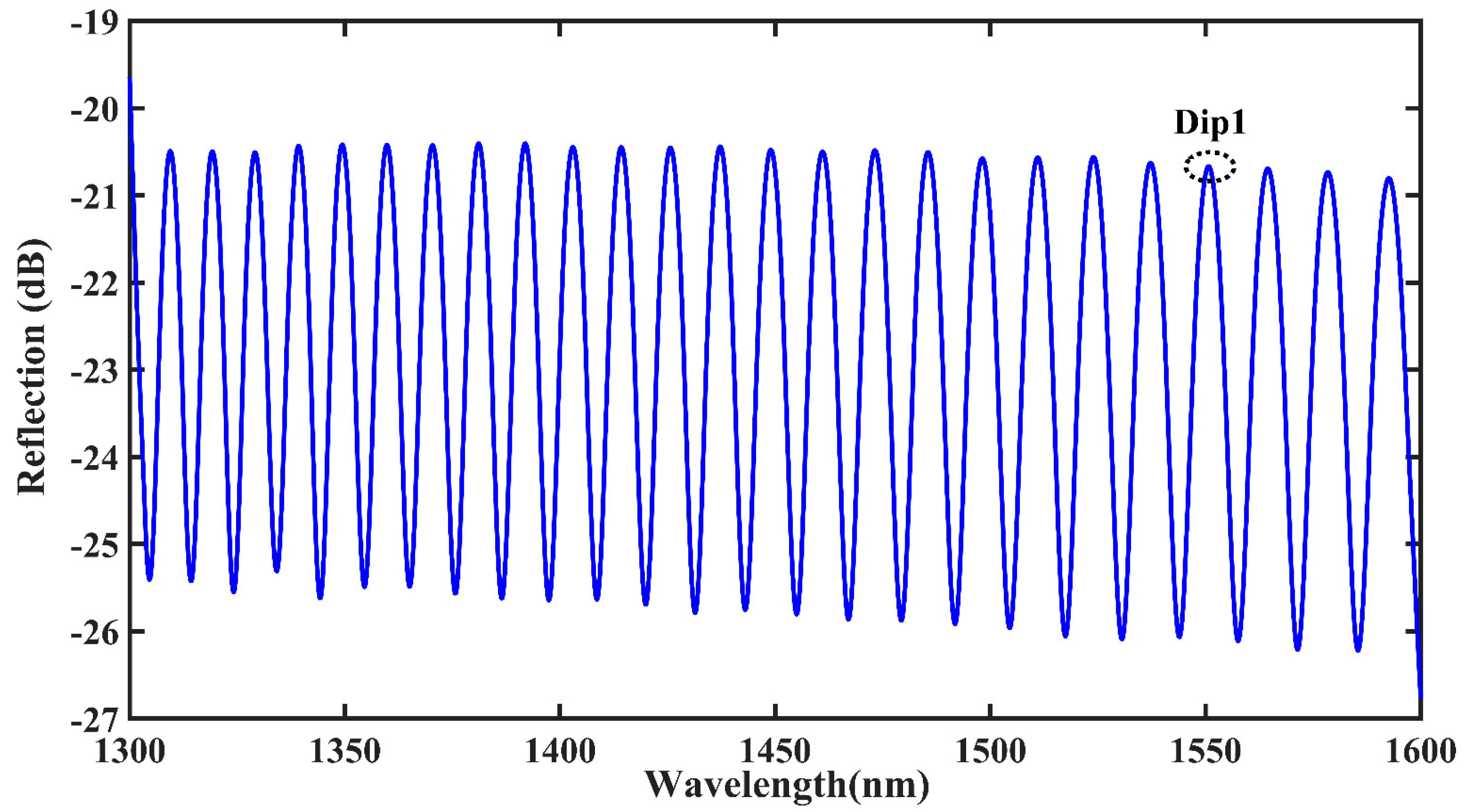
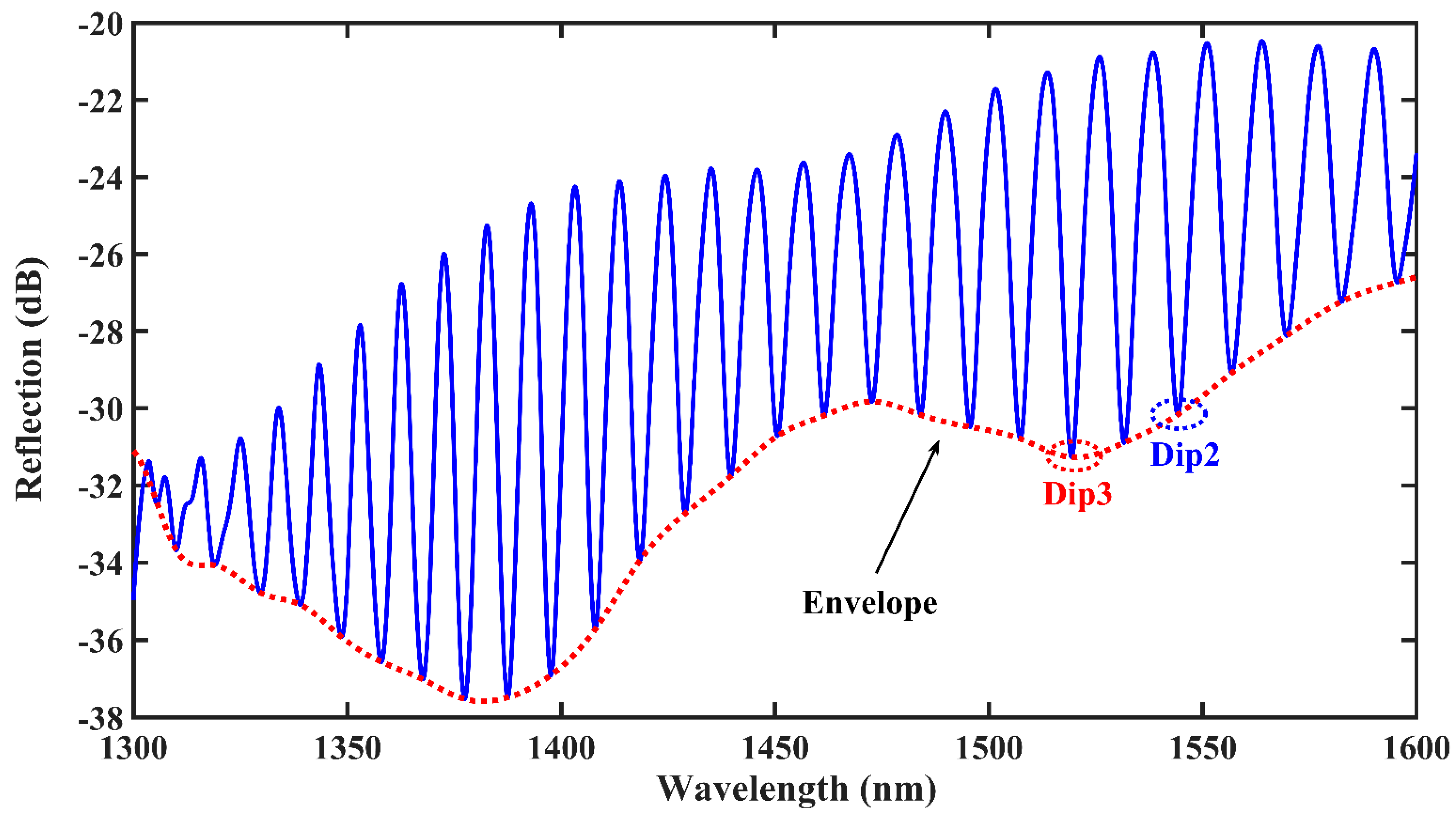
The initial spectrum of a single bubble is depicted in Figure 2, and dip1 at approximately 1550 nm in the communication band is considered as the object of study. The initial spectrum of the double bubble is illustrated in Figure 3, and dip2 at approximately 1550 nm in the communication band is considered as the next object of study. As the double bubbles are closer in size, they interact with each other and the initial spectrum exhibits a clear downward envelope, as shown in the red curve in Figure 3. Further, dip3 at roughly 1520 nm is considered as the third object of study.

4. Experimental Results and Discussion

4.1. Axial Strain Experiment

First, The Broadband Light Source (BBS, FL-ASE) and Optical Spectrum Analyzer (OSA, YOKOGAWA, AQ6370D) were connected to the SMF at both ends of the sensor. The spectral range of BBS adopted in the experiments was 1250–1650 nm, the maximum measurement range of OSA was 600–1700 nm with an accuracy of ±0.02 nm. Then, the fabricated sensing structures were placed in setups as in Figure 4 for axial strain experiments.
As shown in Figure 4, the sensor structure was fixed on two horizontal and equal height precision displacement platforms with UV glue, and the experiment was started after the glue was completely dried. To begin with, the displacement platform was adjusted so that the sensor was in a straightened state. Subsequently, the micrometer of the precision displacement platform on the right side was adjusted, where one frame of micrometer was adjusted each time and a set of data was recorded. Axial strain calculation formula is
ε = Δ d d
where Δd is the total movement of the displacement stage, d is the distance between two fixed points in the initial state, and ε is the axial strain. The distances between the two fixed points of the single-bubble and double-bubble sensing structures were 18.7 cm and 17.3 cm, respectively. The right knob was adjusted one frame at a time, which was 10 μm. Moreover, the data were recorded after the spectrum was stabilized to ensure the accuracy of the experiment.
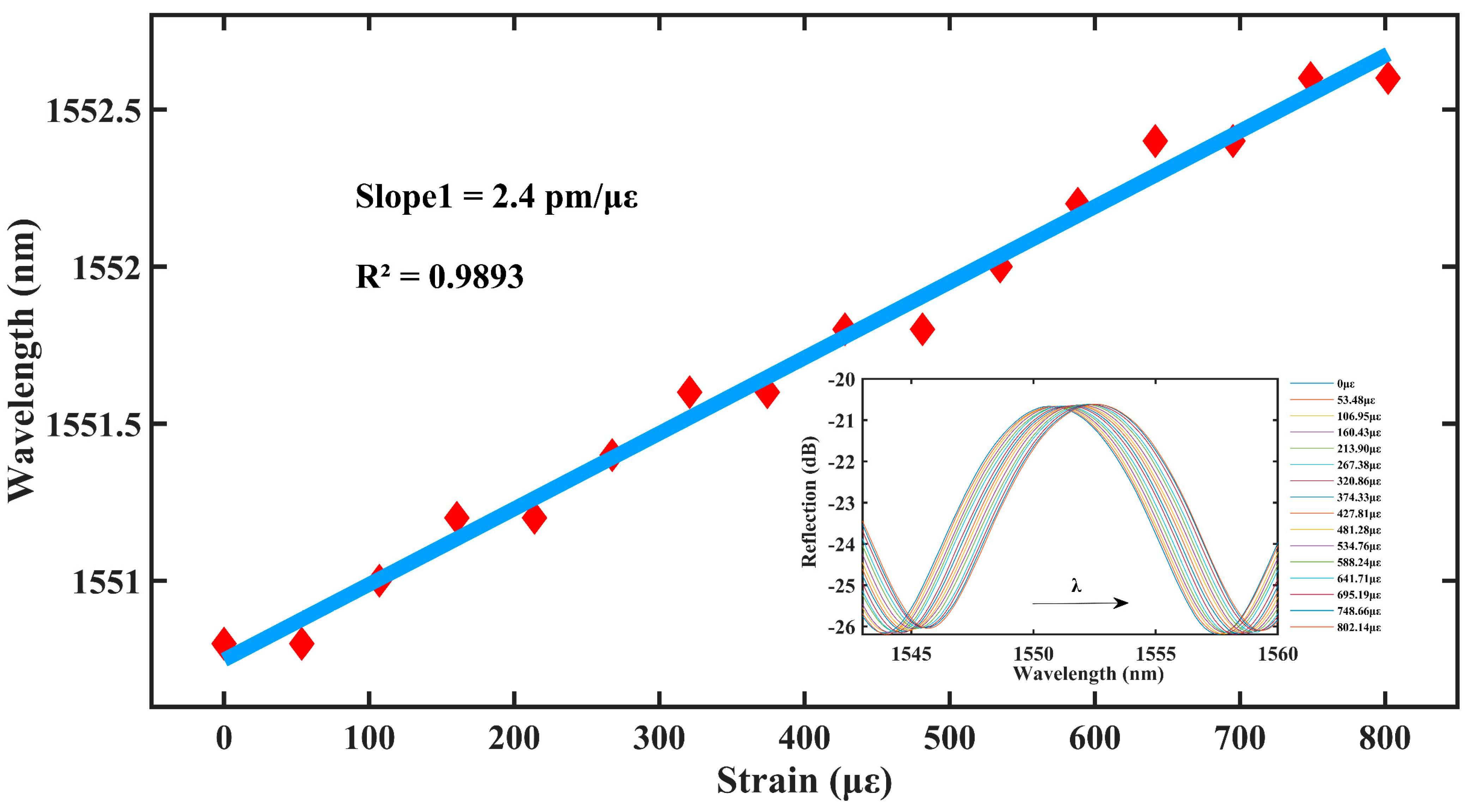
As shown in Figure 5, the central wavelength of the sensor resonance peak dip1 is red-shifted within the axial strain range of 0–802.14 με. The sensitivity of the sensor to axial strain reaches 2.4 pm/με, and the linearity fit reaches 0.9893, thus, exhibiting an excellent linear relationship and high sensitivity.
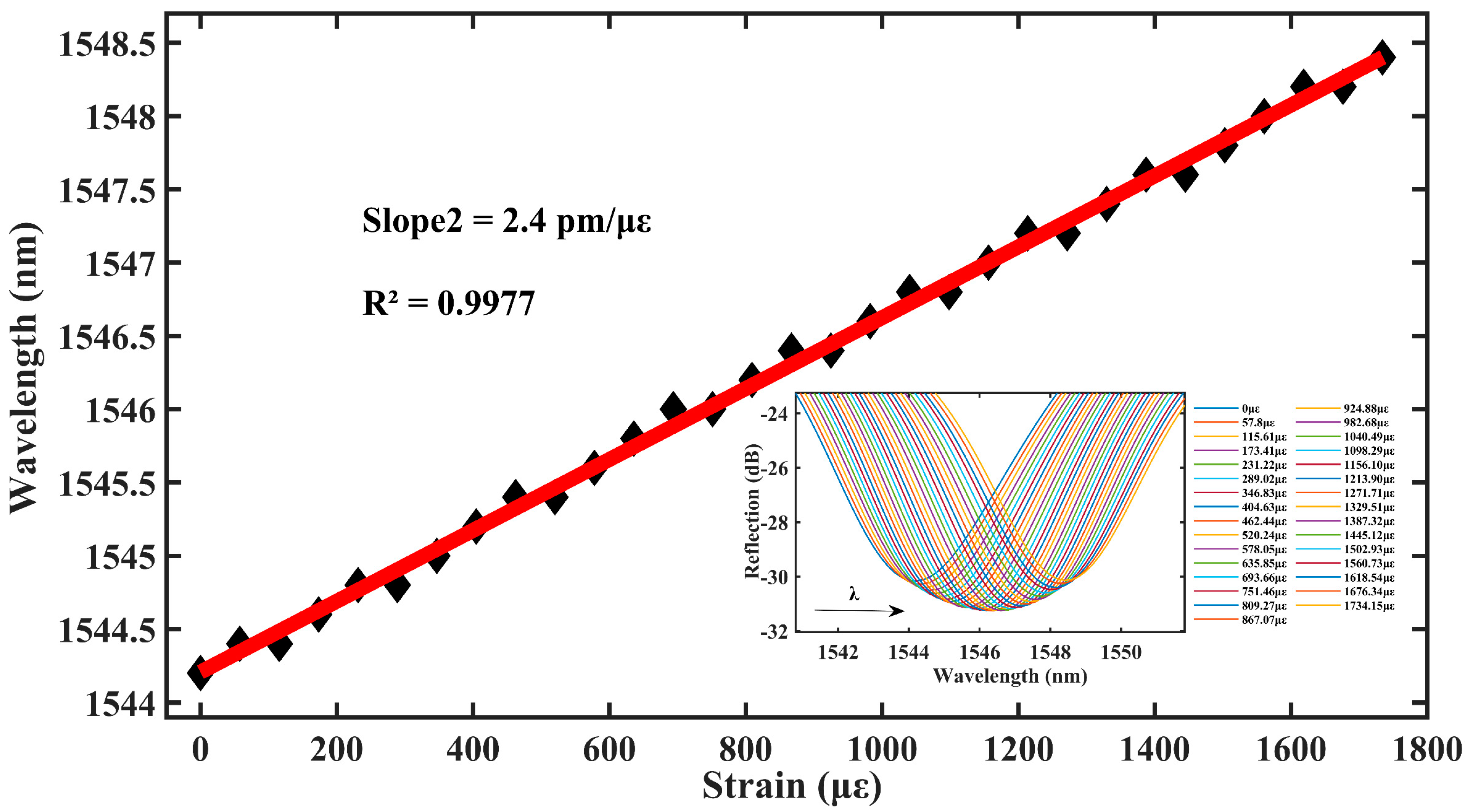
As shown in Figure 6, the central wavelength of the sensor resonance peak dip2 is red-shifted with increase in the axial strain intensity. In the axial strain range of 0–1734.15 με, the sensitivity of the axial strain of the fiber sensor remains 2.4 pm/με with a linear fit of 0.9977. This indicates that the range of the double bubble is more than double compared with that of the single bubble, although the sensitivity of the strain remains the same.
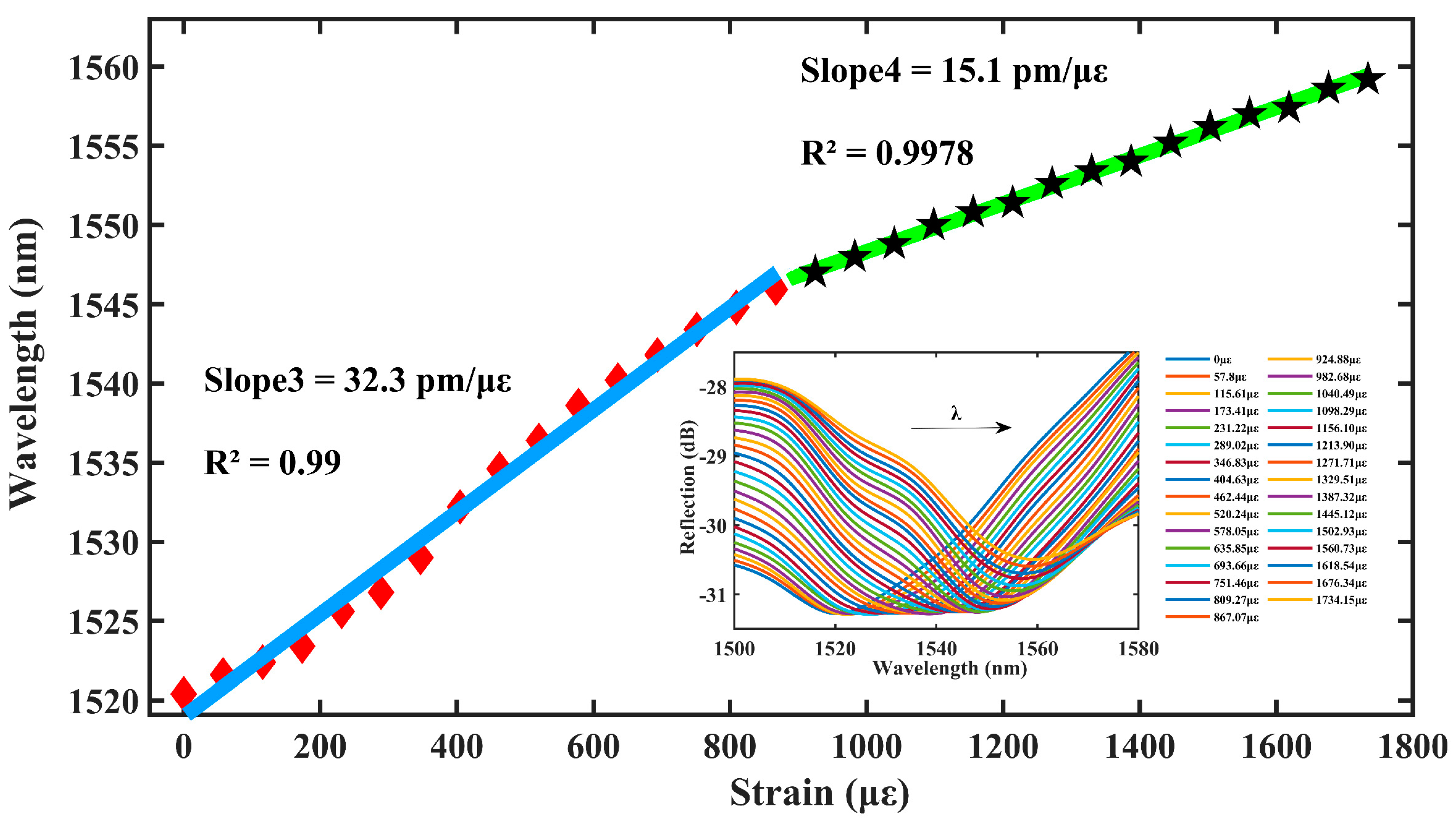
As shown in Figure 7, the red envelope of Figure 3 is used as a drift plot, and the central wavelength of the sensor resonance peak dip3 is continuously red-shifted when the intensity of the axial strain increases. In the axial strain range of 0–867.07 με, the strain sensitivity of the sensor is 32.3 pm/με with a linear fit of 0.99; in the axial strain range from 867.07–1734.15 με, the strain sensitivity of the sensor is 15.1 pm/με with a linear fit of 0.9978.
It is assumed that one of the microcavities is not affected by the external environment and is considered as the reference cavity, while the other is the sensing cavity. Theoretically, we substitute the lengths of the two microcavities into Equation (9) to find the magnification of 9.24 or 10.24.
The amplification effect is further complicated by the fact that both microcavities are subjected to strain at the same time in this experiment. The results show that the two microcavities respond to strain in opposite directions in the first half range of 0–867.07 με, thus, enhancing the vernier effect on sensitivity with a magnification of 13.45. In the second half range of 867.07–1734.15 με, the response to the strain is in the same direction, thus, weakening the effect of the vernier effect on the sensitivity with a magnification of 6.29. Moreover, the wide strain measurement ranges up to 1734.15 με, which indicates the robustness of the device.

4.2. Temperature Experiment

To investigate the stain sensitivity of the fiber optic sensor, the cross-sensitivity to temperature must be considered.
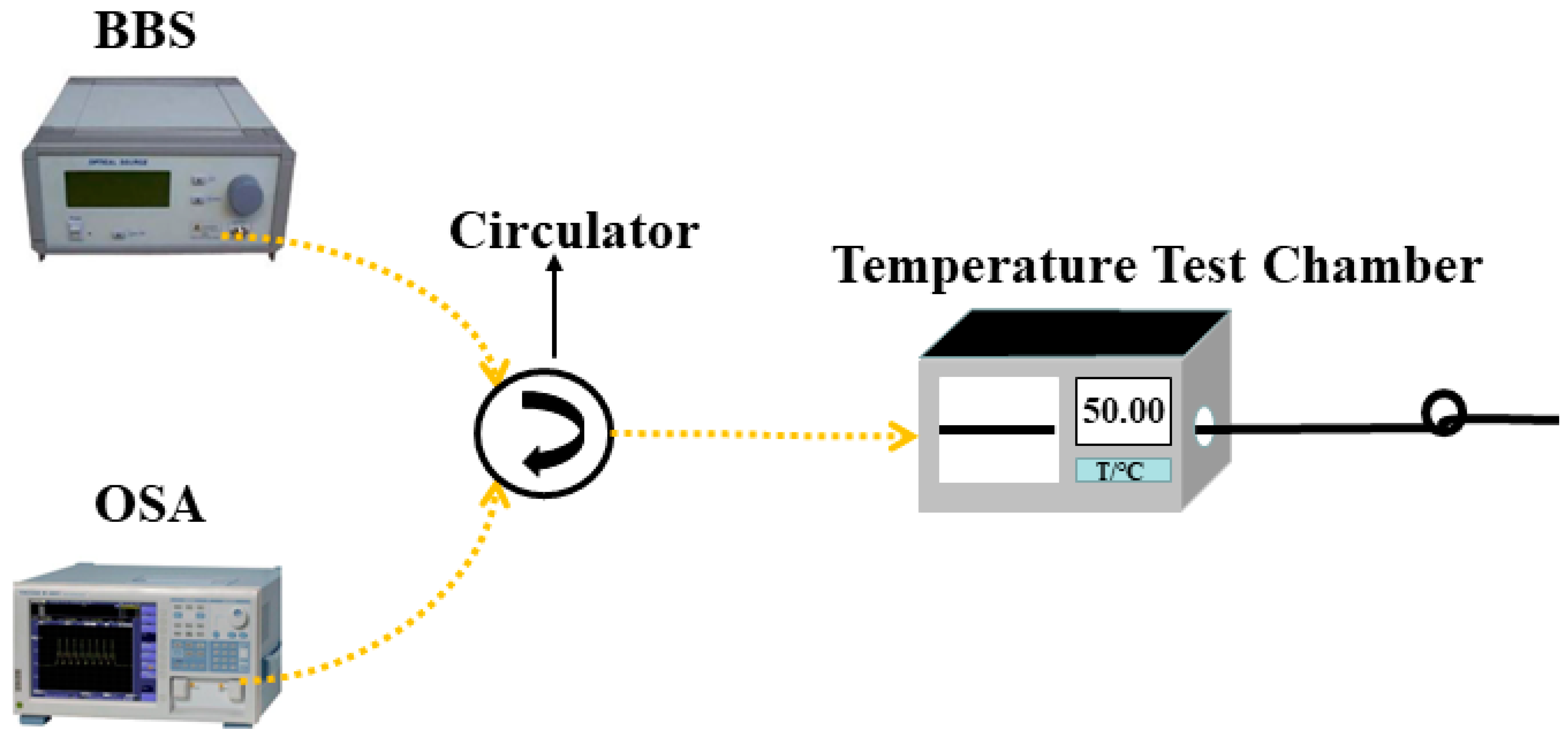
The experimental setup for sensor temperature measurement is shown in Figure 8. The fabricated sensor structure was straightened and placed horizontally in the middle of the experimental chamber (OTF-1200X, KEJING Materials Co., Hefei, China) with one end connected to BBS and OSA, and the other end was cut diagonally to avoid reflections from the end face. A programmable constant temperature test chamber was used in the experiment to simulate the temperature change of the external environment with a temperature accuracy of ±0.1 °C. The temperature experiment was ramped up uniformly from 25–80 °C, and the reflection spectra of the sensors were recorded at an interval of 5 °C.
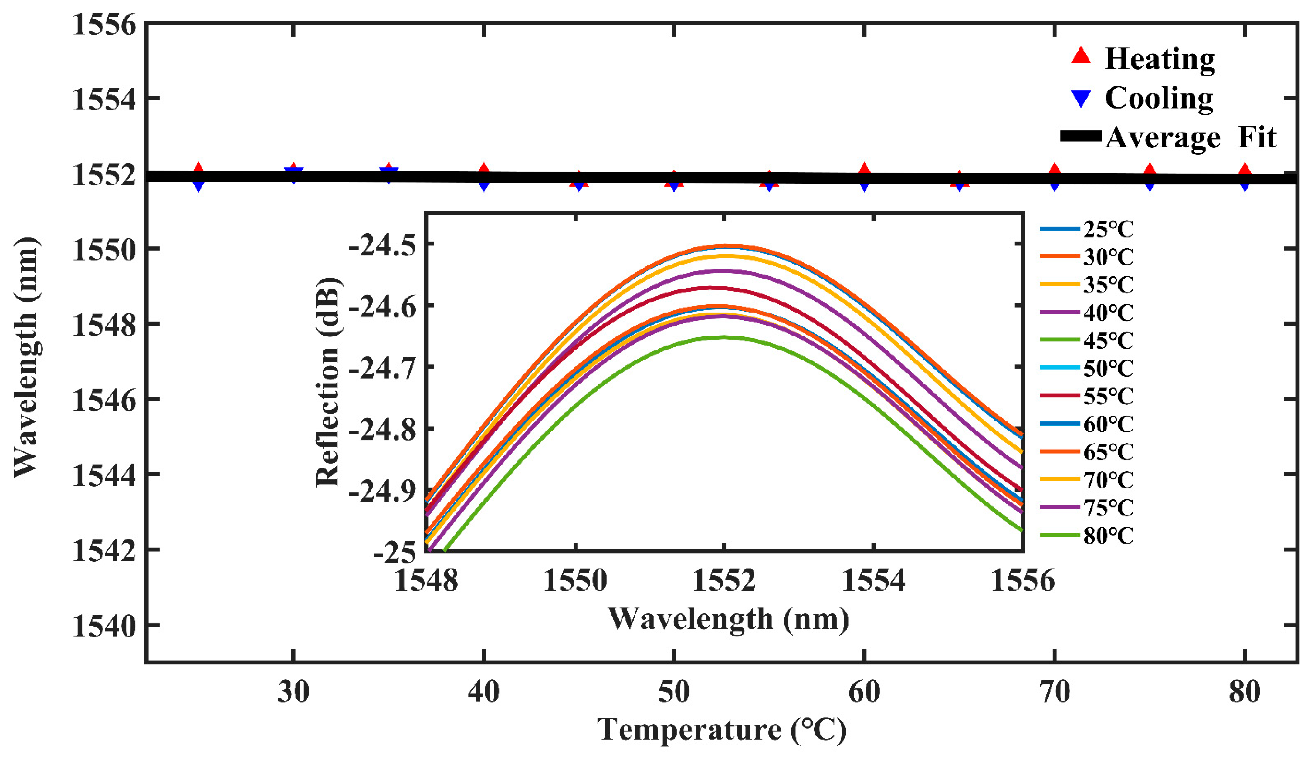
To ensure the repeatability of the sensor, we conducted a temperature reduction experiment in steps of 5 °C from 80 °C to 25 °C. By analyzing the data, we find that the structure’s sensitivity to temperature is also very weak. As shown in Figure 9, it can be seen that the temperature changes from 25 °C to 80 °C have a small effect on the intensity of the spectra. A comprehensive observation of the temperature rise and fall shows that the maximum drift is only 0.05 nm. Therefore, the maximum sensitivity to temperature fluctuations of 0.91 pm/°C can be seen to be almost negligible. The cross effect of temperature could be neglected, additional temperature compensation was no longer needed, and the sensing system could be greatly simplified.
Table 1 gives a comparison between our sensor and previously reported sensors, and our sensor performs very well in terms of a comprehensive evaluation of measurement range, strain sensitivity, and temperature cross-sensitivity.

5. Conclusions

In summary, this study proposed a new type of FPI strain sensor with dual air cavities in the SMF, which was fabricated via femtosecond laser direct writing of two short lines in the core of a standard SMF, followed by discharge using a fiber fusion splicer. Owing to the high temperature generated by the fiber fusion, the line structure instantly expands and forms two separate microcavities simultaneously. The strain sensitivity is increased to 32.3 pm/με with a measuring range of 1734.15 µε. The strain sensitivity has a maximum magnification of 13.45 and the cross-sensitivity of temperature is very small and negligible. Thus, the interferometer allows the design of temperature-independent and ultrasensitive strain sensors. The prepared device is compact, with the sensing area being less than 200 μm in length, and it is easy to fabricate. Furthermore, the proposed fiber optic FPI strain sensor offers the advantages of robust structure and stable measuring, all of which make it attractive for many micro-strain sensing fields.

Author Contributions

Z.L.: writing—original draft preparation; C.L. (Changning Liu): supervision, writing—review and editing; C.L. (Chi Li): software and data curation; J.R.: formal analysis; L.Y.: investigation and funding acquisition. All authors have read and agreed to the published version of the manuscript.

Funding

This work is supported by the National Natural Science Foundation of China (12004105), Program for Innovative Teams of Outstanding Young and Middle-aged Researchers in the Higher Education Institutions of Hubei Province (Grant No. T2020014 and T2021010), Open Fund of Laboratory of Solid-State Microstructures (Grant No. M35054), and the National Undergraduate Training Program for Innovation and Entrepreneurship of Hubei Normal University (Grand NO. 202210513008).

Institutional Review Board Statement

Not applicable.

Informed Consent Statement

Not applicable.

Data Availability Statement

Data underlying the results presented in this paper are not publicly available at this time but may be obtained from the authors upon reasonable request.

Conflicts of Interest

The authors declare no conflict of interest.

References

  1. Lin, H.; Liu, F.; Dai, Y.; Zhou, A. Cascaded fiber Mach–Zehnder interferometers for sensitivity-enhanced gas pressure measurement. IEEE Sens. J. 2018, 19, 2581–2586. [Google Scholar] [CrossRef]
  2. Xu, B.; Liu, Y.M.; Wang, D.N.; Jia, D.; Jiang, C. Optical fiber Fabry–Pérot interferometer based on an air cavity for gas pressure sensing. IEEE Photonics J. 2017, 9, 1–9. [Google Scholar] [CrossRef]
  3. Liu, C.N.; Tao, W.Q.; Chen, C.; Liao, Y. Fabricating Air Pressure Sensors in Hollow-Core Fiber Using Femtosecond Laser Pulse. Micromachines 2023, 14, 101. [Google Scholar] [CrossRef] [PubMed]
  4. Vigneswaran, D.; Ayyanar, N.; Sharma, M.; Sumathi, M.; Rajan, M.; Porsezian, K. Salinity sensor using photonic crystal fiber. Sens. Actuators A Phys. 2018, 269, 22–28. [Google Scholar] [CrossRef]
  5. Qian, Y.; Zhao, Y.; Wu, Q.L.; Yang, Y. Review of salinity measurement technology based on optical fiber sensor. Sens. Actuators B Chem. 2018, 260, 86–105. [Google Scholar] [CrossRef]
  6. Yu, H.; Luo, Z.; Zheng, Y.; Ma, J.; Jiang, X.; Jiang, D. Vibration sensing using liquid-filled photonic crystal fiber with a central air-bore. J. Light. Technol. 2019, 37, 4625–4633. [Google Scholar] [CrossRef]
  7. Zhou, C.; Tian, T.; Qian, L.; Fan, D.; Liang, W.; Ou, Y. Doppler effect-based optical fiber vibration sensor using frequency-shifted interferometry demodulation. J. Light. Technol. 2017, 35, 3483–3488. [Google Scholar] [CrossRef]
  8. Chen, D.; Qian, J.; Liu, J.; Chen, B.; An, G.; Hong, Y.; Jia, P.; Xiong, J. An In-Line Fiber Optic Fabry-Perot Sensor for High-Temperature Vibration Measurement. Micromachines 2020, 11, 252. [Google Scholar] [CrossRef]
  9. Zhao, Y.F.; Jia, Z.N.; Dai, M.L.; Zhao, C.Y.; Gandhi, M.S.A.; Sun, S.Q.; Li, Q.; Fu, H.Y. Cascaded fiber non-adiabatic taper and Sagnac loop for refractive index sensing. Sens. Actuators A Phys. 2021, 332, 113212. [Google Scholar] [CrossRef]
  10. Lei, X.; Dong, X.; Sun, T.; Grattan, K.T. Ultrasensitive Refractive Index Sensor Based on Mach–Zehnder Interferometer and a 40 μm Fiber. J. Light. Technol. 2021, 39, 5625–5633. [Google Scholar] [CrossRef]
  11. Wang, Y.; Gao, R.; Xin, X. Hollow-core fiber refractive index sensor with high sensitivity and large dynamic range based on a multiple mode transmission mechanism. Opt. Express 2021, 29, 19703–19714. [Google Scholar] [CrossRef]
  12. Chen, N.; Liu, C.N.; Lu, Z.Q.; Tao, W.Q.; Peng, M. Femtosecond laser processing for a high sensitivity fiber MZI microcavity. Opt. Express 2022, 30, 12397–12408. [Google Scholar] [CrossRef]
  13. Wang, D.N. Review of femtosecond laser fabricated optical fiber high temperature sensors. Chin. Opt. Lett. 2021, 19, 091204. [Google Scholar] [CrossRef]
  14. Ma, J.W.; Wu, S.; Cheng, H.H.; Yang, X.M.; Wang, S.; Lu, P.X. Sensitivity-enhanced temperature sensor based on encapsulated S-taper fiber Modal interferometer. Opt. Laser Technol. 2021, 139, 106933. [Google Scholar] [CrossRef]
  15. Gang, T.T.; Tong, R.X.; Bian, C. A novel strain sensor using a fiber taper cascaded with an air bubble based on Fabry–Pérot interferometer. IEEE Sens. J. 2020, 21, 4618–4622. [Google Scholar] [CrossRef]
  16. Zhang, F.; Qi, B.; Su, B.; Xu, O.; Qin, Y. High Sensitivity Hollow-Core Fiber Strain Sensor Based on Signal Processing Assisted Vernier Effect. IEEE Photonics Technol. Lett. 2022, 34, 1050–1053. [Google Scholar] [CrossRef]
  17. Bai, Y.; Yan, F.P.; Liu, S.; Wen, X.D. All fiber Fabry–Pérot interferometer for high-sensitive micro-displacement sensing. Opt. Quantum Electron. 2016, 48, 206. [Google Scholar] [CrossRef]
  18. Liu, X.H.; Jiang, M.S.; Sui, Q.M.; Geng, X.Y. Optical fiber Fabry–Perot relative humidity sensor based on HCPCF and chitosan film. J. Mod. Opt. 2016, 63, 1668–1674. [Google Scholar] [CrossRef]
  19. Liao, C.R.; Wang, D.N.; Wang, Y. Microfiber in-line Mach–Zehnder interferometer for strain sensing. Opt. Lett. 2013, 38, 757–759. [Google Scholar] [CrossRef]
  20. Dong, X.R.; Du, H.F.; Sun, X.Y.; Luo, Z.; Duan, J.A. A novel strain sensor with large measurement range based on all fiber Mach-Zehnder interferometer. Sensors 2018, 18, 1549. [Google Scholar] [CrossRef]
  21. Frazão, O.; Marques, L.M.; Santos, S.; Baptista, J.M.; Santos, J.L. Simultaneous measurement for strain and temperature based on a long-period grating combined with a high-birefringence fiber loop mirror. IEEE Photonics Technol. Lett. 2006, 18, 2407–2409. [Google Scholar] [CrossRef]
  22. Pan, X.P.; Guo, Q.; Wu, Y.D.; Liu, S.R.; Wang, B.; Yu, Y.S.; Sun, H.B. Femtosecond laser inscribed chirped fiber Bragg gratings. Opt. Lett. 2021, 46, 2059–2062. [Google Scholar] [CrossRef] [PubMed]
  23. Vorathin, E.; Hafizi, Z.M.; Aizzuddin, A.M.; Lim, K.S. A natural rubber diaphragm-based transducer for simultaneous pressure and temperature measurement by using a single FBG. Opt. Fiber Technol. 2018, 45, 8–13. [Google Scholar] [CrossRef]
  24. Favero, F.C.; Araujo, L.; Bouwmans, G.; Finazzi, V.; Villatoro, J.; Pruneri, V. Spheroidal Fabry-Perot microcavities in optical fibers for high-sensitivity sensing. Opt. Express 2012, 20, 7112–7118. [Google Scholar] [CrossRef]
  25. Dong, X.R.; Luo, Z.; Du, H.F.; Sun, X.Y.; Yin, K.; Duan, J.A. Highly sensitive strain sensor based on a novel Mach–Zehnder mode interferometer with TCF-PCF-TCF structure. Opt. Lasers Eng. 2019, 116, 26–31. [Google Scholar] [CrossRef]
  26. Tian, J.; Jiao, Y.; Ji, S.; Dong, X.; Yao, Y. Cascaded-cavity Fabry–Perot interferometer for simultaneous measurement of temperature and strain with cross-sensitivity compensation. Opt. Commun. 2018, 412, 121–126. [Google Scholar] [CrossRef]
  27. Wu, Y.; Zhang, Y.; Wu, J.; Yuan, P. Temperature-insensitive fiber optic Fabry-Perot interferometer based on special air cavity for transverse load and strain measurements. Opt. Express 2017, 25, 9443–9448. [Google Scholar] [CrossRef]
  28. Liu, S.; Wang, Y.; Liao, C.; Wang, G.; Li, Z.; Wang, Q.; Tang, J. High-sensitivity strain sensor based on in-fiber improved Fabry–Perot interferometer. Opt. Lett. 2014, 39, 2121–2124. [Google Scholar] [CrossRef]
  29. Zhang, C.; Ning, T.; Zheng, J.; Xu, J.; Gao, X.; Lin, H.; Pei, L. An optical fiber strain sensor by using of taper based TCF structure. Opt. Laser Technol. 2019, 120, 105687. [Google Scholar] [CrossRef]
  30. Tian, K.; Zhang, M.; Farrell, G.; Wang, R.; Lewis, E.; Wang, P. Highly sensitive strain sensor based on composite interference established within S-tapered multimode fiber structure. Opt. Express 2018, 26, 33982–33992. [Google Scholar] [CrossRef]
  31. Domínguez-Flores, C.E.; Rodríguez-Quiroz, O.; Monzon-Hernandez, D.; Ascorbe, J.; Corres, J.M.; Arregui, F.J. Dual-Cavity Fiber Fabry-Perot Interferometer Coated with SnO2 for Relative Humidity and Temperature Sensing. IEEE Sens. J. 2020, 20, 14195–14201. [Google Scholar] [CrossRef]
  32. Lee, C.L.; Ma, C.T.; Yeh, K.C.; Chen, Y.M. A Dual-Cavity Fiber Fabry–Pérot Interferometer for Simultaneous Measurement of Thermo-Optic and Thermal Expansion Coefficients of a Polymer. Polymers 2022, 14, 4966. [Google Scholar] [CrossRef] [PubMed]
  33. Pullteap, S.; Seat, H.C.; Bosch, T. Modified fringe-counting technique applied to a dual-cavity fiber Fabry-Pérot vibrometer. Opt. Eng. 2007, 46, 115603. [Google Scholar] [CrossRef]
  34. Zhang, L.; Jiang, Y.; Gao, H.; Jia, J.; Cui, Y.; Wang, S.; Hu, J. Simultaneous measurements of temperature and pressure with a dual-cavity Fabry–Perot sensor. IEEE Photonics Technol. Lett. 2018, 31, 106–109. [Google Scholar] [CrossRef]
  35. Cui, Y.; Jiang, Y.; Liu, T.; Hu, J.; Jiang, L. A dual-cavity Fabry–Perot interferometric fiber-optic sensor for the simultaneous measurement of high-temperature and high-gas-pressure. IEEE Access 2020, 8, 80582–80587. [Google Scholar] [CrossRef]
  36. Quan, M.R.; Tian, J.J.; Yao, Y. Ultra-high sensitivity Fabry–Perot interferometer gas refractive index fiber sensor based on photonic crystal fiber and Vernier effect. Opt. Lett. 2015, 40, 4891–4894. [Google Scholar] [CrossRef] [PubMed]
  37. Li, Y.; Zhao, C.L.; Wang, D.N.; Yang, M.H. Optical cascaded Fabry–Perot interferometer hydrogen sensor based on vernier effect. Opt. Commun. 2018, 414, 166–171. [Google Scholar] [CrossRef]
  38. Deng, J.; Wang, D.N. Ultra-sensitive strain sensor based on femtosecond laser inscribed in-fiber reflection mirrors and Vernier effect. J. Light. Technol. 2019, 37, 4935–4939. [Google Scholar] [CrossRef]
  39. Wang, Y.; Wang, D.N.; Liao, C.R.; Hu, T.Y.; Guo, J.T.; Wei, H.F. Temperature-insensitive refractive index sensing by use of micro Fabry–Pérot cavity based on simplified hollow-core photonic crystal fiber. Opt. Lett. 2013, 38, 269–271. [Google Scholar] [CrossRef]
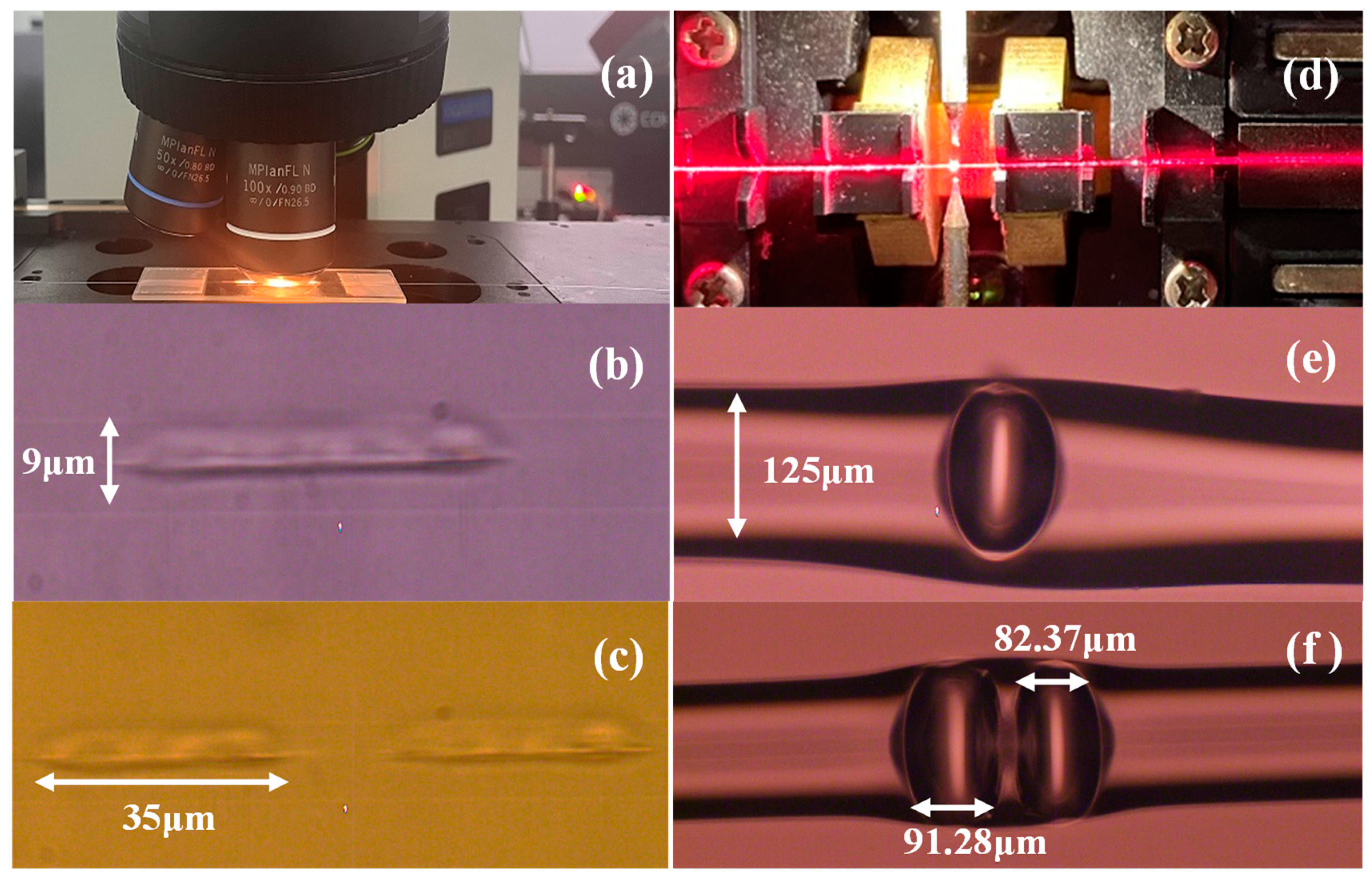
Figure 1. (a) Fabrication system for femtosecond laser scribing; (b) a horizontal short-line structure inscribed in fiber core; (c) two horizontal short-line structures inscribed in fiber core; (d) discharge the short-line area; (e,f) one or two bubbles are formed.
Materials 16 03165 g001
Figure 2. Original spectrum of single bubble.
Materials 16 03165 g002
Figure 3. Original spectrum of double bubbles.
Materials 16 03165 g003
Figure 4. Schematic of strain experimental setup.
Materials 16 03165 g004
Figure 5. Single bubble of strain drift and fit plots.
Materials 16 03165 g005
Figure 6. Double bubble strain drift and fit plots before magnification.
Materials 16 03165 g006
Figure 7. Double bubble strain drift and fit plots after magnification.
Materials 16 03165 g007
Figure 8. Schematic of temperature experimental setup.
Materials 16 03165 g008
Figure 9. Experiment setup of the temperature sensing system based on cascaded FPIs.
Materials 16 03165 g009
Table 1. Comparisons of the proposed sensors with other representative structures.
Ref.Device StructureStrain
Sensitivity
Measurement
Range of Strain
Temperature
Sensitivity
[22]FBGs1.21 pm/µε0–3138 με14.91 pm/°C
[24]Spheroidal FP cavities10.3 pm/με0–1100 με1 pm/°C
[25]Hollow-core PCF1.89 pm/µε0–4000 με5.58 pm/°C
[26]Cascaded FP cavities2.97 pm/με0–1000 με0.9 pm/°C
[27]FPI with air cavity3.29 pm/με0–1100 με1.08 pm/°C
[28]FPIs6.0 pm/με0–1000 με1 pm/°C
[29]Tapered-based TCF6.11 pm/με0–841.5 με0.69 pm/°C
[30]S-tapered with MMF103.8 pm/με0–170 με36.2 pm/°C
[38]FPI based on Vernier effect28.11 pm/με0–1500 με278.48 pm/°C
This workFPIs32.3 pm/με0–1734.15 με0.91 pm/°C
Disclaimer/Publisher’s Note: The statements, opinions and data contained in all publications are solely those of the individual author(s) and contributor(s) and not of MDPI and/or the editor(s). MDPI and/or the editor(s) disclaim responsibility for any injury to people or property resulting from any ideas, methods, instructions or products referred to in the content.