
Multi-Objective Optimization Design and Performance Comparison of Magnetorheological Torsional Vibration Absorbers of Different Configurations

Abstract
:1. Introduction
2. Materials and Methods
2.1. Materials
2.2. Structure and Magnetic Circuit Design
2.3. Modeling and Simulation
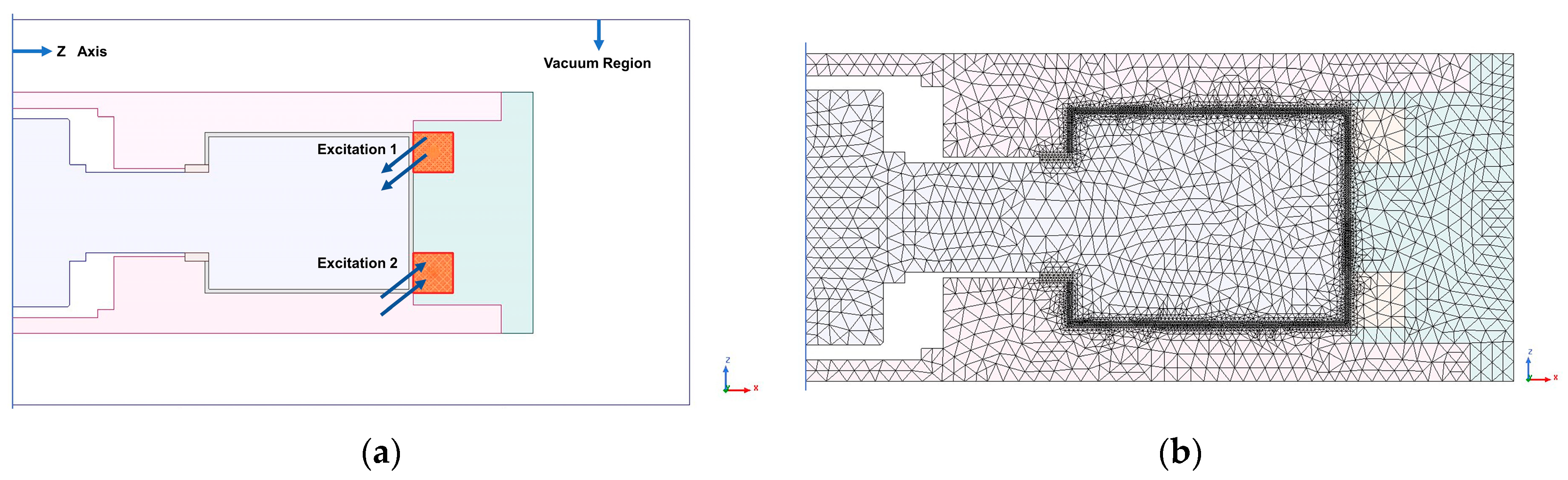
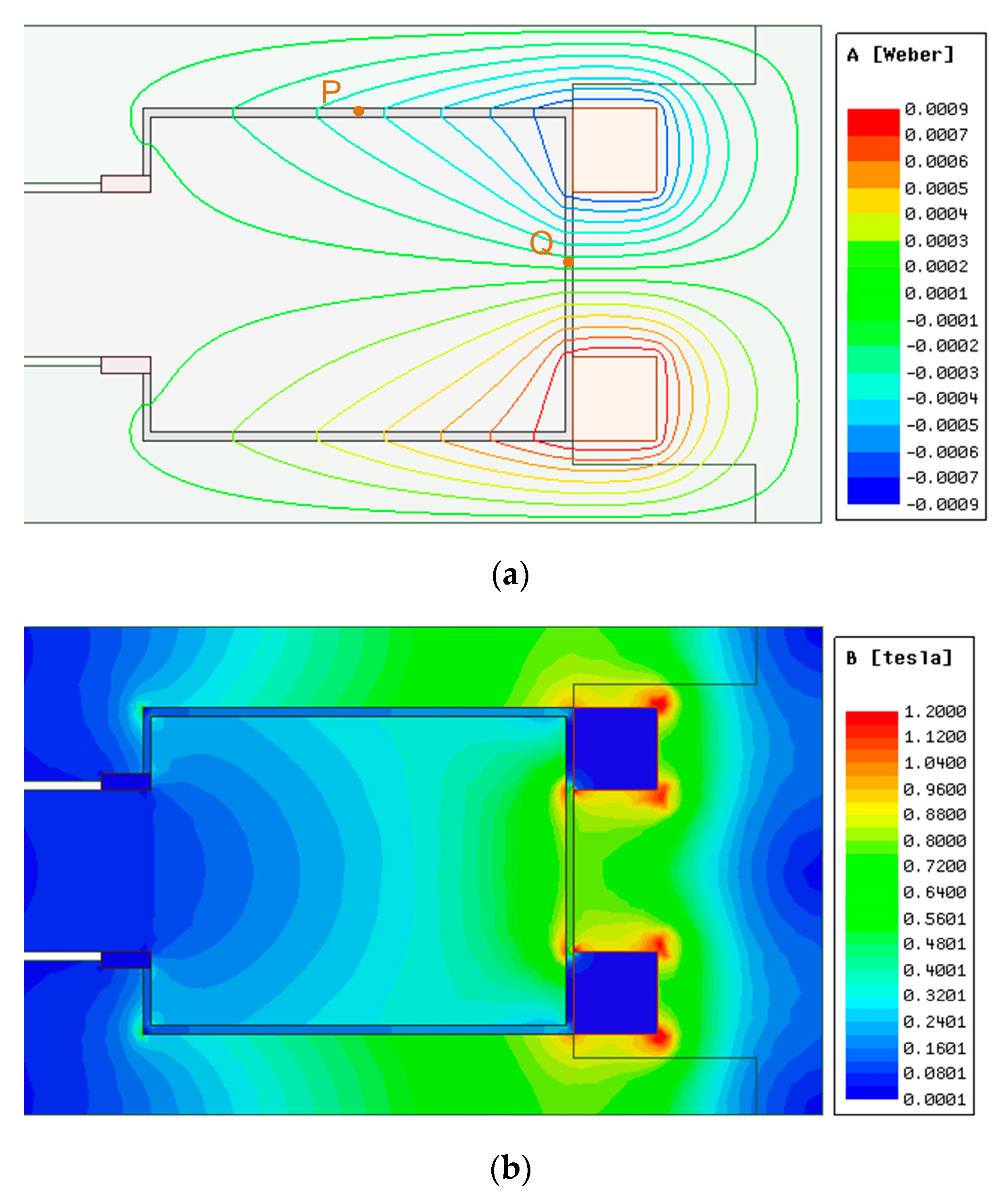
2.3.1. Magnetic Circuit Model Establishment and Magnetic Field Finite Element Analysis
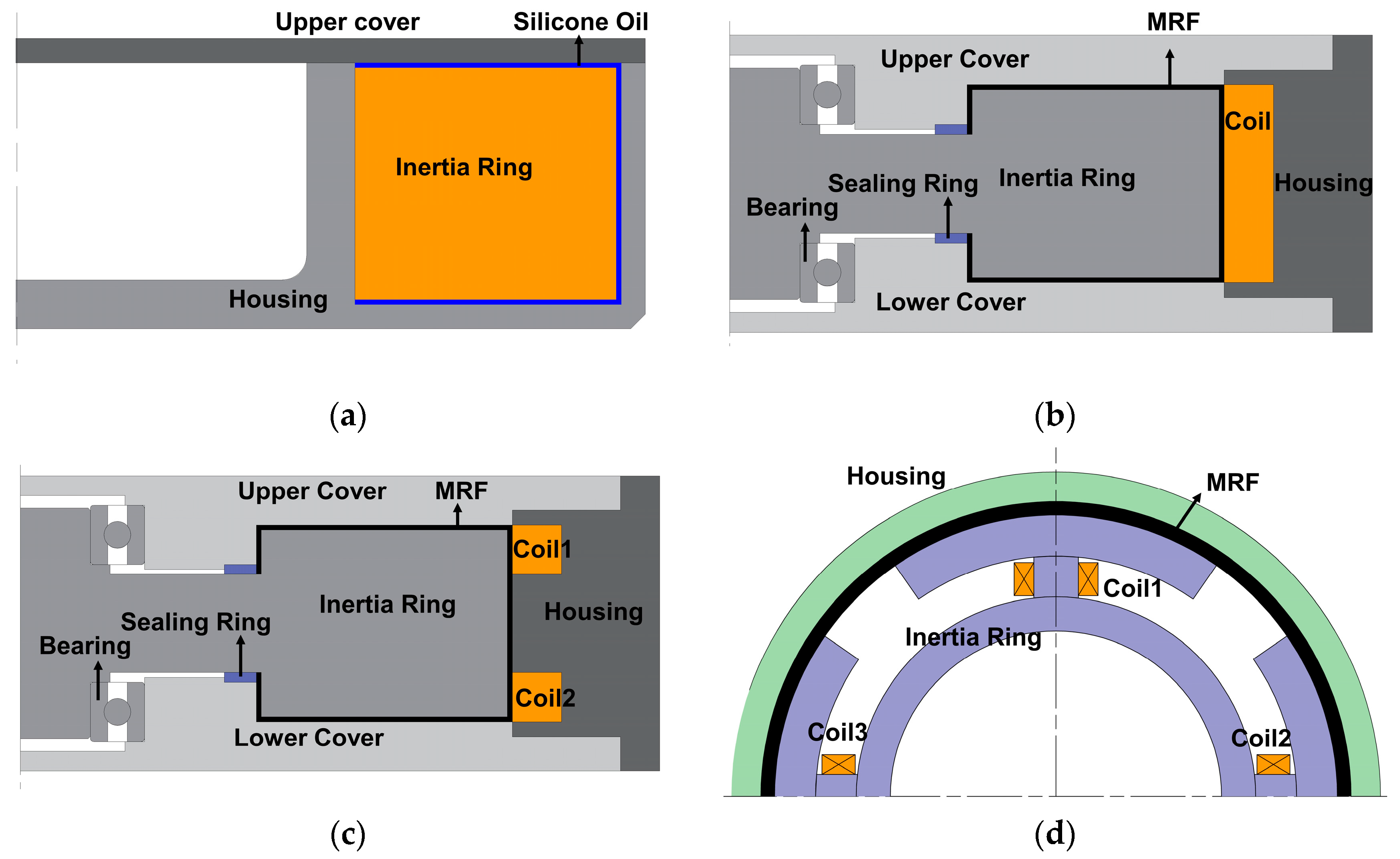
- Axial single-coil configuration;
- Axial multi-coil configuration;
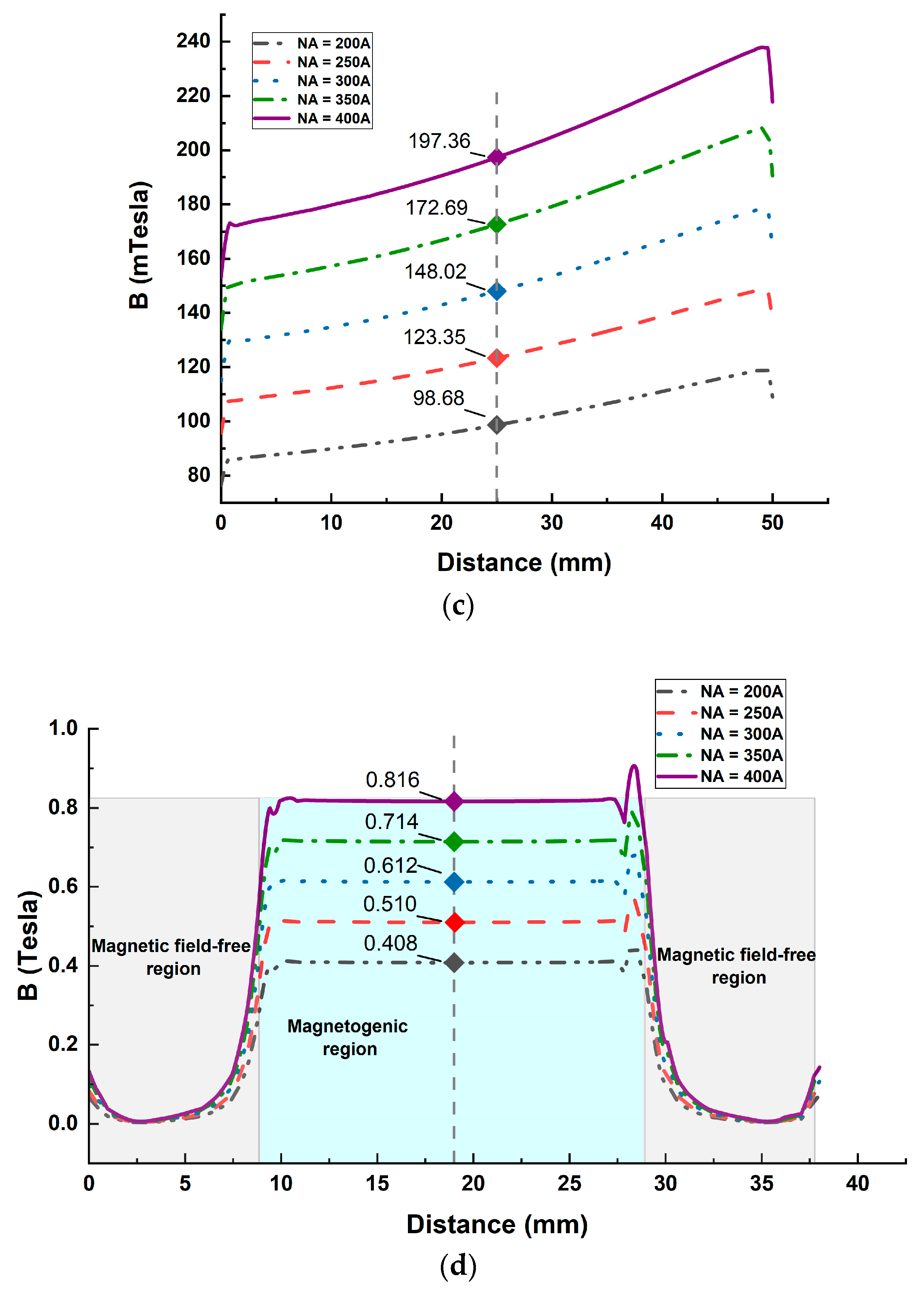
- Circumferential configuration;
2.3.2. Damping Torque Model Establishment
- Axial single-coil configuration;
- Axial multi-coil configuration;
- Axial circumferential configuration;
2.3.3. Response Time Model Establishment
- Axial single-coil configuration;
- Axial multi-coil configuration;
- Axial circumferential configuration;
3. Results and Discussion
3.1. The Optimization of Mass and Damping Torque
3.2. The Optimization of Damping Torque and Response Time
3.3. The Optimization Result and Discussion
4. Conclusions
- (1)
- Axial single-coil configuration can provide a fairly high damping torque, but its response time is much longer than the other configurations. In addition, the axial single-coil configuration has the simplest structure arrangement and is more convenient in design and performance prediction. Therefore, the axial single-coil configuration is suitable for engines and related rotating machines with high output power and relatively simple working conditions.
- (2)
- Axial multi-coil configuration has high utilization of magnetic field and MR material, so it can provide high damping torque. The adjacent arrangement of the coils for axial multi-coil configuration reduces the circuit self-inductance, which makes its response time much less than the other configurations. Therefore, the axial multi-coil configuration is suitable for engines and other rotating machines with high output power and complicated working conditions.
- (3)
- The circumferential configuration has the highest utilization rate of the overall structure and the lowest mass in the MR-TVA of the same specification. However, the circumferential configuration has the longest magnetic circuit and the largest magnetic field loss, which results in the smallest damping torque provided in the MR-TVA of the same specification. Therefore, the circumferential configuration is suitable for engines with low output power and slow speed changes.
Author Contributions
Funding
Institutional Review Board Statement
Informed Consent Statement
Data Availability Statement
Conflicts of Interest
Appendix A
References
- Jolly, M. Properties and applications of commercial magnetorheological fluids. J. Intell. Mater. Syst. Struct. 1999, 10, 5–13. [Google Scholar]
- Wang, J.; Meng, G. MR fluid devices: Principles, characteristics and applications in mechanical engineering. Proc. Inst. Mech. Eng. Part K. J. Multi-Body Dyn. 2001, 215, 165–174. [Google Scholar]
- Ding, Y.; Zhang, L.; Zhu, H.-T.; Li, Z.-X. A new magnetorheological damper for seismic control. Smart Mater. Struct. 2013, 22, 115003. [Google Scholar] [CrossRef]
- Flores, G. Embolization of blood vessels as a cancer therapy using magnetorheological fluids. J. Intell. Mater. Syst. Struct. 2002, 13, 641–646. [Google Scholar] [CrossRef]
- Chen, J.; Liao, W.-H. A leg exoskeleton utilizing a factuator. In Proceedings of the IEEE International Conference on Robotics and Biomimetics (ROBIO), Kunming, China, 17–20 December 2006. [Google Scholar]
- Kordonski, W.I.; Golini, D. Fundamentals of magnetorheological fluid utilization in high precision finishing. J. Intell. Mater. Syst. Struct. 1999, 10, 683–689. [Google Scholar] [CrossRef]
- Fitrian, I.; Mazlan, S.A.; Hairi, Z. A design and modelling review of rotary magnetorheological damper. Mater. Des. 2013, 51, 575–591. [Google Scholar]
- Charles, P.; Sinha, J.K.; Gu, F.; Lidstone, L.; Ballm, A.D. Detecting the crankshaft torsional vibration of diesel engines for combustion related diagnosis. J. Sound Vib. 2009, 321, 1171–1185. [Google Scholar] [CrossRef]
- Periyasamy, S.; Alwarsamy, T. Combined effects of inertia and pressure on engine vibration. J. Vib. Control 2012, 19, 2469–2480. [Google Scholar] [CrossRef]
- Miles, T.J.; Lucas, M.; Halliwell, N.A.; Rothberg, S.J. Torsional and bending vibration measurement on rotors using laser technology. J. Sound Vib. 1999, 226, 441–467. [Google Scholar] [CrossRef]
- Fonte, M.; Freitas, M.D. Marine main engine crankshaft failure analysis: A case study. Eng. Fail. Anal. 2009, 16, 1940–1947. [Google Scholar] [CrossRef]
- Kim, G.W. Piezoelectric energy harvesting from torsional vibration in internal combustion engines. Int. J. Automot. Technol. 2015, 16, 645–651. [Google Scholar] [CrossRef]
- Alevras, P.; Theodossiades, S. Vibration energy harvester for variable speed rotor applications using passively self-tuned beams. J. Sound Vib. 2019, 444, 176–196. [Google Scholar] [CrossRef]
- Azizi, S.; Madinei, H.; Taghipour, J.; Ouakad, H. Bifurcation analysis and nonlinear dynamics of a capacitive energy harvester in the vicinity of the primary and secondary resonances. Nonlinear Dyn. 2022, 108, 873–886. [Google Scholar] [CrossRef]
- Al-Riyami, M.; Bahadur, I.; Ouakad, H. There is plenty of room inside a bluff body: A hybrid piezoelectric and electromagnetic wind energy harvester. Energies 2022, 15, 6097. [Google Scholar] [CrossRef]
- Mendes, A.S.; Meirelles, P.S.; Zampieri, D.E. Analysis of torsional vibration in internal combustion engines: Modelling and experimental validation. Proc. Inst. Mech. Eng. Part K J. Multi-Body Dyn. 2008, 222, 155–178. [Google Scholar] [CrossRef]
- Silva, C.A.F.; Manin, L.; Rinaldi, R.G.; Besnier, E.; Remond, D. Dynamics of torsional vibration damper (TVD) pulley, implementation of a rubber elastomeric behavior, simulations and experiments. Mech. Mach. Theory 2019, 142, 103583. [Google Scholar] [CrossRef]
- Nguyen, Q.H.; Choi, S.B. Optimal design of a T-shaped drum-type brake for motorcycle utilizing magnetorheological fluid. Mech. Based Des. Struct. Mach. 2012, 40, 153–162. [Google Scholar]
- Shiao, Y.J.; Nguyen, Q.A.; Lin, J.W. The development of a hybrid antilock braking system using magnetorheological brake. Appl. Mech. Mater. 2014, 479, 622–626. [Google Scholar]
- He, W.; Ouyang, Q.; Hu, H.; Ye, X.; Lin, L. Semi-active control of crankshaft skyhook based on magnetorheological torsional damper. Front. Mater. 2022, 9, 933076. [Google Scholar] [CrossRef]
- Hoang, N.; Cao, D. Design of a torsional dynamic absorber using magnetorheological elastomers for powertrain vibration control. Adv. Mater. Res. 2011, 1273, 372–376. [Google Scholar]
- Hoang, N.; Zhang, N.; Li, W.H.; Du, H. Development of a torsional dynamic absorber using a magnetorheological elastomer for vibration reduction of a powertrain test rig. J. Intell. Mater. Syst. Struct. 2013, 24, 2036–2044. [Google Scholar] [CrossRef]
- Nguyen, Q.; Choi, S. Optimal design of a magneto-rheological brake absorber for torsional vibration control. Smart Mater. Struct. 2012, 21, 025001. [Google Scholar] [CrossRef]
- Ehab, A.; Rama, B.; Ramin, S. Development of a new torsional vibration damper incorporating conventional centrifugal pendulum absorber and magnetorheological damper. J. Intell. Mater. Syst. Struct. 2016, 27, 980–992. [Google Scholar]
- Shenoy, K.P.; Singh, A.K.; Raman, K.S.A.; Gangadharan, K.V. Experimental investigation of torsional vibration isolation using Magneto Rheological Elastomer. MATEC Web Conf. 2018, 144, 01007. [Google Scholar] [CrossRef]
- Gao, P.; Liu, H.; Xiang, C.; Yan, P.; Mahmoud, T. A new magnetorheological elastomer torsional vibration absorber: Structural design and performance test. Mech. Sci. 2021, 12, 321–332. [Google Scholar] [CrossRef]
- Dong, X.; Li, W.; Yu, J.; Pan, C.; Xi, J.; Zhou, Y.; Wang, X. Magneto-rheological variable stiffness and damping torsional vibration control of powertrain system. Front. Mater. 2020, 7, 121. [Google Scholar] [CrossRef]
- Xiao, Z.; Hu, H.; Ouyang, Q.; Shan, L.; Su, H. Multi-condition temperature field simulation analysis of magnetorheological grease torsional vibration damper. Front. Mater. 2022, 9, 930825. [Google Scholar] [CrossRef]
- Homik, W. The effect of liquid temperature and viscosity on the amplitude-frequency characteristics of a viscotic torsion damper. Pol. Marit. Res. 2012, 19, 71–77. [Google Scholar] [CrossRef]
- Homik, W.; Mazurkow, A.; Wos, P. Application of a Thermo-Hydrodynamic Model of a Viscous Torsional Vibration Damper to Determining Its Operating Temperature in a Steady State. Materials 2021, 14, 5234. [Google Scholar] [CrossRef]
- MRF-132DG Magneto-Rheological Fluid. Available online: https://lordfulfillment.com/pdf/44/DS7015_MRF-132DGMRFluid.pdf (accessed on 26 February 2023).


| Parameters | Reference Value | Units |
|---|---|---|
| Zero field viscosity () | 0.1 | Pa.s |
| Yield viscosity () | 3.8 | Pa.s |
| Zero field shear stress () | 15 | Pa |
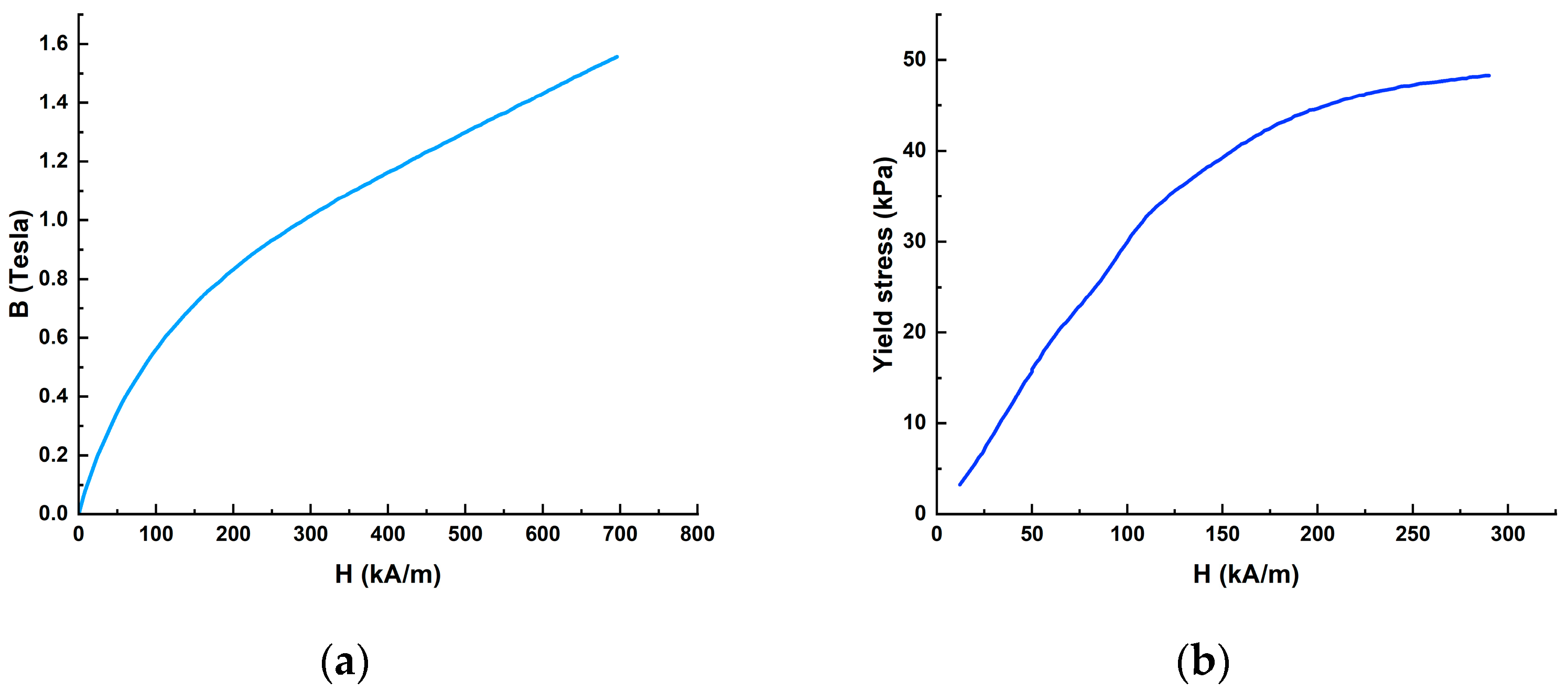
| Shear yield stress () | 40,000 | Pa |
| Relative permeability () | 4.5 | - |
| Configuration | Parameters | Initial Value (mm) |
|---|---|---|
| Axial single-coil configuration and Axial multi-coil configuration | Fluid gap () | 1 |
| Radius of inner ring () | 50 | |
| Radial size of inertia ring () | 50 | |
| Thickness of housing () | 30 | |
| Thickness of cover () | 10 | |
| Thickness of inertia ring () | 38 | |
| Thickness of coil () | 10 | |
| Length of coil () | 10 | |
| Radius of MR-TVA () | 130 | |
| Thickness of MR-TVA () | 60 | |
| Circumferential configuration | Radius of inner ring () | 73 |
| Thickness of inner ring () | 12 | |
| Length of winding post () | 17 | |
| Thickness of outer ring () | 17 | |
| Opening angle of outer ring () | 70° | |
| Thickness of inertia ring () | 36 | |
| Diameter of winding post () | 19.6 | |
| Thickness of magnetic permeable ring () | 5 |
| Ampere-Turns (NA) | FEA (mT) | Magnetic Circuit Model (mT) | Error (%) |
|---|---|---|---|
| 200 | 399.57 | 382.03 | 4.6 |
| 250 | 499.46 | 477.54 | 4.4 |
| 300 | 599.36 | 573.04 | 4.4 |
| 350 | 699.25 | 668.55 | 4.4 |
| 400 | 799.12 | 764.06 | 4.4 |
| Ampere-Turns (NA) | FE Analysis (mT) | Magnetic Circuit Model (mT) | Error (%) |
|---|---|---|---|
| 200 | [98.68, 408.23] | [102.64, 384.91] | 4.0 |
| 250 | [123.35, 510.28] | [128.30, 481.13] | 4.0 |
| 300 | [148.02, 612.34] | [153.96, 577.36] | 3.9 |
| 350 | [172.69, 714.40] | [179.62, 673.59] | 4.0 |
| 400 | [197.36, 815.89] | [205.28, 769.81] | 3.8 |
| Ampere-Turns (NA) | FE Analysis (mT) | Magnetic Circuit Model (mT) | Error (%) |
|---|---|---|---|
| 200 | 68.34 | 63.09 | 7.7 |
| 250 | 85.87 | 78.86 | 8.2 |
| 300 | 103.04 | 94.63 | 8.2 |
| 350 | 120.20 | 110.40 | 8.2 |
| 400 | 136.69 | 126.18 | 7.7 |
| Configuration | Parameters Number | Parameters | Parameters Range (mm) |
|---|---|---|---|
| Axial single-coil configuration & Axial multi-coil configuration | 1 | [10, 60] | |
| 2 | [30, 60] | ||
| 3 | [15, 50] | ||
| 4 | [5, 20] | ||
| 5 | [40, 50] | ||
| Circumferential configuration | 1 | [30, 70] | |
| 2 | [10, 30] | ||
| 3 | [15, 25] | ||
| 4 | [15, 30] | ||
| 5 | (°) | [30, 80] | |
| 6 | [35, 45] | ||
| 7 | [15, 30] | ||
| 8 | [5, 15] |
| Configuration | Parameters Number | Parameters | Parameters Range (mm) |
|---|---|---|---|
| Axial single-coil configuration & Axial multi-coil configuration | 1 | [10, 60] | |
| 2 | [30, 60] | ||
| 3 | [15, 50] | ||
| 4 | [5, 20] | ||
| 5 | [40, 50] | ||
| 6 | [5, 15] | ||
| 7 | [0.8, 1.2] | ||
| Circumferential configuration | 1 | [30, 70] | |
| 2 | [10, 30] | ||
| 3 | [15, 25] | ||
| 4 | [15, 30] | ||
| 5 | (°) | [30, 80] | |
| 6 | [35, 45] | ||
| 7 | [15, 30] | ||
| 8 | [5, 15] | ||
| 9 | [5, 10] | ||
| 10 | [0.5, 1.2] |
| Parameter | Axial Single-Coil Configuration | Axial Multi-Coil Configuration | Circumferential Configuration | |||
|---|---|---|---|---|---|---|
| Optimal Values (mm) | 60 | 60 | 64 | |||
| 45 | 43 | 10 | ||||
| 23 | 23 | 15 | ||||
| 6 | 6 | 27 | ||||
| 40 | 42 | ° | 78 | |||
| 5 | 5 | 43 | ||||
| 1.2 | 1.0 | 29 | ||||
| 7 | ||||||
| 5 | ||||||
| 1.2 | ||||||
| Radius (mm) | 129 | 127 | 129 | |||
| Mass (kg) | 19.59 | 19.23 | 11.03 | |||
| Response (s) | 1.84 | 0.14 | 0.45 | |||
| Torque (N.m) | 207.05 | 210.01 | 65.60 | |||
Disclaimer/Publisher’s Note: The statements, opinions and data contained in all publications are solely those of the individual author(s) and contributor(s) and not of MDPI and/or the editor(s). MDPI and/or the editor(s) disclaim responsibility for any injury to people or property resulting from any ideas, methods, instructions or products referred to in the content. |
© 2023 by the authors. Licensee MDPI, Basel, Switzerland. This article is an open access article distributed under the terms and conditions of the Creative Commons Attribution (CC BY) license (https://creativecommons.org/licenses/by/4.0/).
Share and Cite
Liu, G.; Hu, H.; Ouyang, Q.; Zhang, F. Multi-Objective Optimization Design and Performance Comparison of Magnetorheological Torsional Vibration Absorbers of Different Configurations. Materials 2023, 16, 3170. https://doi.org/10.3390/ma16083170
Liu G, Hu H, Ouyang Q, Zhang F. Multi-Objective Optimization Design and Performance Comparison of Magnetorheological Torsional Vibration Absorbers of Different Configurations. Materials. 2023; 16(8):3170. https://doi.org/10.3390/ma16083170
Chicago/Turabian StyleLiu, Guisheng, Hongsheng Hu, Qing Ouyang, and Feng Zhang. 2023. "Multi-Objective Optimization Design and Performance Comparison of Magnetorheological Torsional Vibration Absorbers of Different Configurations" Materials 16, no. 8: 3170. https://doi.org/10.3390/ma16083170