Article

An Artificial MnWO4 Cathode Electrolyte Interphase Enabling Enhanced Electrochemical Performance of δ-MnO2 Cathode for Aqueous Zinc Ion Battery

Key Laboratory of Advanced Ceramics and Machining Technology of Ministry of Education, School of Materials Science and Engineering, Tianjin University, Tianjin 300072, China
*
Author to whom correspondence should be addressed.
Materials 2023, 16(8), 3228; https://doi.org/10.3390/ma16083228
Submission received: 23 March 2023 / Revised: 12 April 2023 / Accepted: 15 April 2023 / Published: 19 April 2023
(This article belongs to the Topic Electrochemical Energy Storage Materials)

Abstract

:
The dissolution of active material in aqueous batteries can lead to a rapid deterioration in capacity, and the presence of free water can also accelerate the dissolution and trigger some side reactions that affect the service life of aqueous batteries. In this study, a MnWO4 cathode electrolyte interphase (CEI) layer is constructed on a δ-MnO2 cathode by cyclic voltammetry, which is effective in inhibiting the dissolution of Mn and improving the reaction kinetics. As a result, the CEI layer enables the δ-MnO2 cathode to produce a better cycling performance, with the capacity maintained at 98.2% (vs. activated capacity at 500 cycles) after 2000 cycles at 10 A g−1. In comparison, the capacity retention rate is merely 33.4% for pristine samples in the same state, indicating that this MnWO4 CEI layer constructed by using a simple and general electrochemical method can promote the development of MnO2 cathodes for aqueous zinc ion batteries.

1. Introduction

At present, aqueous zinc ion batteries (AZIBs) have been widely studied for energy storage due to various advantages such as low cost, environmental benignity, and high safety performance [1,2,3,4,5,6,7,8,9,10]. So far, there have been various materials reported to be suitable as cathodes for AZIBs, including manganese-based materials [11,12,13,14,15], vanadium-based materials [16,17,18,19,20], and Prussian blue analogs [21,22,23,24]. Among them, manganese oxide has attracted widespread attention because of its abundance, low toxicity, high energy density, and structural diversity [25]. However, Mn dissolution issues still limit the cycling stability of manganese-based materials for AZIBs [26].
In the past decades, there has been some progress made in the research on how to improve the performance of electrode materials [27] and electrolytes [28] in resisting the dissolution of cathodes. Apart from the existing strategies, researchers have also discovered that the construction of an electrode-electrolyte interphase (EEI), including anode electrolyte interphase and cathode electrolyte interphase, can also help improve the energy density, cycling performance, and power density of batteries [29]. Therefore, building the cathode electrolyte interphase (CEI) surface protection layer is considered a feasible solution to the dissolution of cathodes. However, the research on CEI is still limited now due to the complexity of the cathode energy storage mechanism for AZIBs and the difficulty in characterizing various interfacial reactions [30].
Typically, the methods of CEI construction are divided into two categories: in situ formation and artificial synthesis. In recent years, some studies have reportedly been conducted on the in situ formation of CEI. Liang et al. proposed to perform electrochemical synthesis of the CaSO4·2H2O layer in situ on a Ca2MnO4 cathode, which significantly improved the stability and service life of the battery [31]. Cao et al. also built an in situ CEI layer of BaSO4 on the Ba0.26V2O5·0.92H2O cathode of AZIBs, which reduced the dissolution of cathodes, thus leading to an excellent cycling performance [32]. Compared with the synthesis of CEI in situ, the artificial construction of CEI is much easier to manipulate. Xiong et al. synthesized a reduced graphene oxide (rGO) layer coated with α-MnO2 powder, which improved both rate performance and cycling stability [33]. For different coating materials, powder coating may cause hindrances to ion transport to some extent. Unlike the powder coating as described above, the artificial CEI is more similar to cathode coating, where a layer is formed between the cathode and the electrolyte. Guo et al. reported a HfO2 layer formed on a Zn3V2O7(OH)2·2H2O electrode as an artificial solid electrolyte interphase. The HfO2 layer was built by means of atomic layer deposition and is capable of isolating the electrode from the electrolyte, thereby reducing the dissolution of the cathode in the electrolyte and inhibiting the formation of insulated by-products. As a result, the capacity retention rate was considerably improved from 45% to 90% after 100 cycles at 0.1 A g−1 [34]. Based on the construction of the CEI layer and its effect on cycling performance, there have been many studies carried out. For example, Paraffin [35], (Zn(OH)2)3(ZnSO4)(H2O)5 [36], and SrCO3 [37] have been reported as a kind of CEI layer. All these results demonstrate that the construction of CEI is effective in significantly enhancing the electrochemical performance of AZIBs.
For the manganese-based material used in AZIBs, the CEI layer can help prevent the cathode from direct exposure to the electrolyte, which suppresses Mn dissolution, thus maintaining high cycling performance and capacity. However, the strategy of CEI layer construction on manganese-based materials is not universal, and the economic benefits are unsatisfactory. In this study, a CEI layer of MnWO4 is constructed on a δ-MnO2 cathode through a facile electrochemical method (cyclic voltammetry), which not only inhibits the Mn dissolution but also improves the reaction kinetics. The key to this economical and efficient strategy lies in the dissolution of the Mn-based cathode in solutions that do not co-exist with Mn2+ ions. The prepared MnWO4-coated δ-MnO2 (denoted as W-MnO2) shows an outstanding cycling performance (98.2% capacity retention vs. activated capacity at 500 cycles, after 2000 cycles at 10 A g−1), indicating the effectiveness of the CEI construction strategy. In addition, the low-cost strategy of the CEI layer can be applied to other manganese-based AZIBs.

2. Experimental Section

2.1. Materials Preparation

The synthesis of the cubic MnCO3 precursor was performed in the way as reported by others [38]. Firstly, 25 mL of 0.8 M NH4HCO3 aqueous solution, 25 mL of n-butanol, and 500 mL of cyclohexane were thoroughly mixed. Then, 20 g of cetyltrimethylammonium bromide (CTAB) was added into the mixed solution and stirred until it became clear. Next, 25 mL of 0.4 M MnSO4 aqueous solution was added dropwise into the solution, which led to a white precipitate. Afterwards, the precipitate was collected through centrifugation, washed clean with alcohol and distilled water, respectively, and dried under vacuum at 100 °C to obtain white MnCO3. To further oxidize MnCO3 into MnO2 [39,40], 1 g of the synthesized MnCO3 precursor was added into 0.032 M of KMnO4 aqueous solution. Then, the mixed solution was subjected to ultrasonic treatment for 30 min and stirred for 1 day. The δ-MnO2 precursor was collected by centrifugation, washed (three times) with alcohol and distilled water, and finally dried at 75 °C.
The δ-MnO2 cathode was produced by using N-methylpirpiridone (NMP) as a solvent to disperse the precursor powder (δ-MnO2, 70 wt%), conductive additive (Super P, 20 wt%), and binder (PVDF, 10 wt%), and was coated on carbon fiber paper. The loading density of the cathode was set to about 1.5 mg cm−2.
The MnWO4-coated δ-MnO2 (W-MnO2) was constructed in a conventional three-electrode configuration by cyclic voltammetry (CV) at a scan rate of 50 mV/s (negative scan from −0.6 to 0.6 V for 100 segments). The electrolyte was 0.1 mol/L Na2WO4 solution, and the pH value was adjusted to 7 by using H2SO4. The pristine δ-MnO2 cathode was treated as the working electrode of the three-electrode system, while Ag/AgCl and graphite were taken as the reference and counter electrodes, respectively. Finally, W-MnO2 was obtained by washing it thoroughly with distilled water (three times) and drying it at 75 °C. The loading density of the W-MnO2 cathode was approximately 0.5–1% higher than the pristine cathode.

2.2. Materials Characterization

X-ray diffraction (XRD, D8 Advance, Bruker, Cu Kα) data were collected at a scan range of 5–70° (2θ) and a step size of 0.02°. Both SEM (Sigma 300, Zeiss, operating voltage 5 kV) and HR-TEM (JEM-2100F, JEOL) were employed to examine the morphology and microstructure of the samples. X-ray photoelectron spectroscopy (XPS, PHI-1600, PerkinElmer) was performed to record the valence states of the samples loaded with Cu. The C 1s peak with a binding energy of 284.8 eV was used to calibrate all XPS spectra. Nitrogen adsorption measurements for Brunauer–Emmett–Teller (BET) analysis were tested at 77 K using an ASAP 2460.

2.3. Electrochemical Measurements

The 2032-type coin cells were assembled with prepared W-MnO2 as the cathode, a Zn foil as the counter electrode, and an aqueous ZnSO4 (3 M) solution with a MnSO4 additive (0.2 M) as the electrolyte. The CV and EIS (100 kHz to 10 mHz) were measured on a CHI 660E electrochemical workstation. To conduct the CV tests at different scan rates, the peak current ( i ) and scan rate (ν) were determined through Equation (1) [41]:
i = a ν b ,
where a and b represent variable parameters, and the b-value is obtained through the slope of log( i ) vs. log(ν). Furthermore, the current contribution is divided into capacitive and diffusion contributions according to Equation (2) [42]:
i = k 1 V + k 2 V 1 2 ,
where k1 and k2 refer to the coefficients of proportionality for capacitive and diffusion contributions, respectively. The GCD curves, cycling performance, and GITT measurements were achieved by using the LAND CT2001A battery test system at room temperature. Moreover, the pause and rest time of GITT at 0.2 A g−1 lasted 10 min and 180 min, respectively. The diffusion coefficient can be determined through the following equation [43]:
D = 4 l 2 π τ ,
where D represents the diffusion coefficient, l indicates the diffusion length (cm) of active materials, and τ refers to the duration of the current pause (s). ΔEs and ΔEt represent the voltage difference by the current pulse and the voltage difference during the constant current pulse, respectively.

3. Results and Discussion

The MnWO4-coated δ-MnO2 (W-MnO2) was obtained by means of the electrochemical treatment (cyclic voltammetry) conducted in a three-electrode system, as shown in Figure 1a. The working electrode was the δ-MnO2 cathode. Figures S1 and S2 show the XRD and BET results of δ-MnO2 powder, respectively. According to the N2 adsorption isotherm, the specific area of δ-MnO2 is 20 m2 g−1. To confirm the chemical composition of the CEI layer on the δ-MnO2 cathode, XRD was performed for the W-MnO2 cathode, as shown in Figure 1b. In addition to the weak characteristic peaks of δ-MnO2, a peak appears at 18° corresponding to MnWO4 (JCPDS No. 72-0478) after the CV process. Moreover, there are some other characteristic peaks of MnWO4 observed at around 37° and 52°, indicating the presence of the MnWO4 after the CV process. It is suspected that the absence of the δ-MnO2 characteristic peaks may result from the limited crystallinity of δ-MnO2 and the strong diffraction peak of the carbon fiber paper. XPS was performed to determine the Mn valence during the CV process. As shown in Figure 1c, the splitting magnitude of two splitting components for the Mn 3s peak increases to 6.13 eV from 4.87 eV after the electrochemical treatment. In general, the Mn 3s peak consists of two multiple splitting components [11,44], with the oxidation state of Mn determined by the splitting magnitude ΔE, which is 6.0 eV and 4.7 eV for Mn2+ and MnO2 (Mn4+), respectively [45]. It can be found that the valence state of Mn shifted from +4 in δ-MnO2 to +2 in W-MnO2, indicating the formation of the MnWO4 on the δ-MnO2 cathode. To determine the effect of MnWO4 formation on the morphology of δ-MnO2 and the area of MnWO4 distribution, SEM and TEM tests were performed. As shown in Figure 1d, the size of δ-MnO2 cubes is approximately 500 nm, and the morphology of the δ-MnO2 cubes is barely changed during the formation of MnWO4 (Figure 1e). The EDS element mapping of W-MnO2 (Figure 1f) shows a uniform distribution of element W on the surface of the MnO2 cube, indicating that the MnWO4 is formed uniformly on the surface of the δ-MnO2 cathode. Moreover, the HRTEM (Figure 1g) images of the W-MnO2 surface show that lattice fringes are 0.22 nm and 0.249 nm, which correspond to the (121) and (002) crystal planes of MnWO4, respectively. Meanwhile, the (121), (002), and (−113) crystal planes of MnWO4 are also observable in the results of selected area electron diffraction (SAED). Judging from the image of TEM (Figure 1f), it can be concluded that MnWO4 was formed on the surface of δ-MnO2 cathodes as a CEI layer. Thus, it can be inferred that during the CV process, the δ-MnO2 surface is partially dissolved and rapidly reacts with WO42- to form MnWO4 during the CV process. Finally, the MnWO4 CEI layer is successfully constructed on the δ-MnO2 cathode.
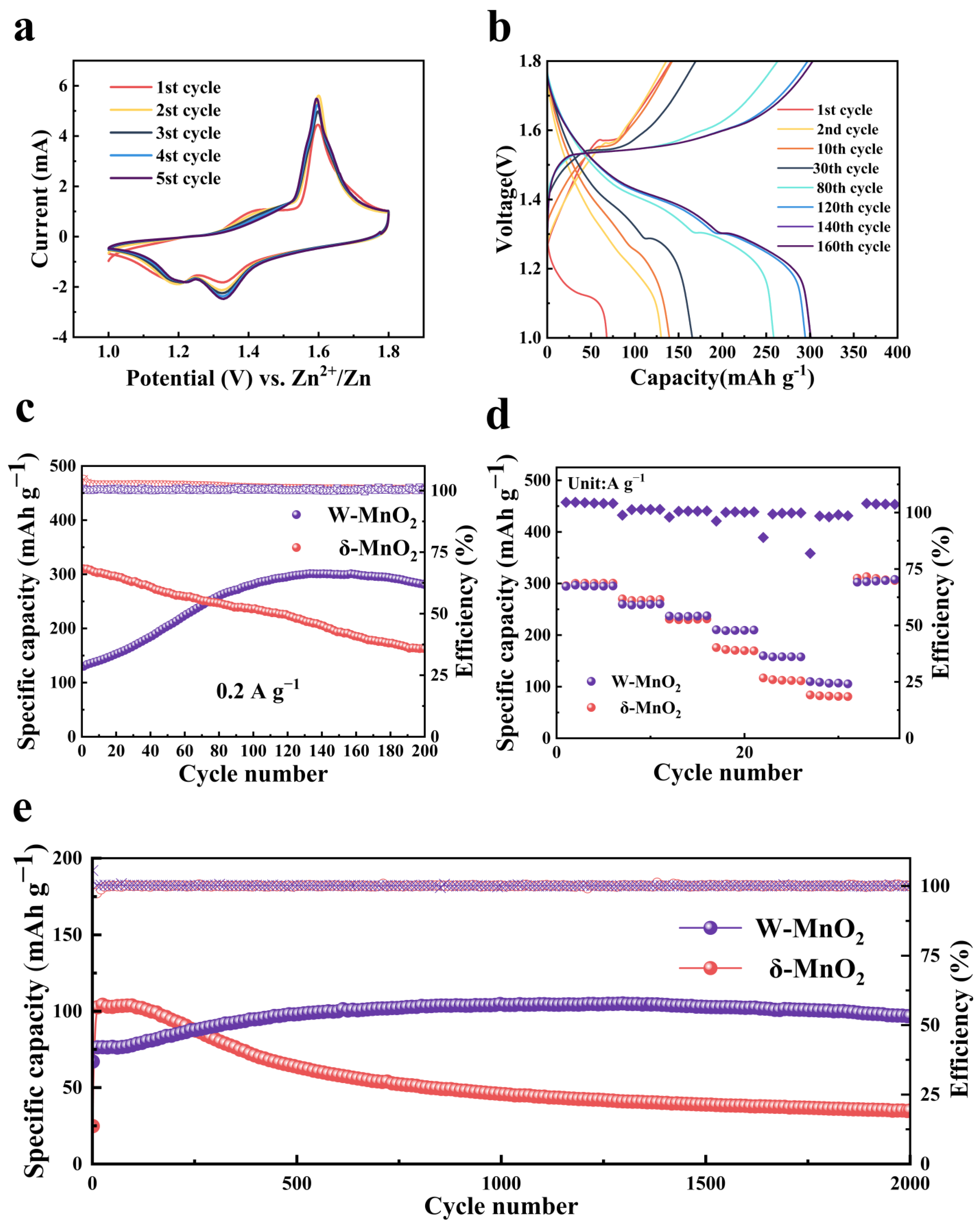
To examine the effect of the MnWO4 CEI layer on the electrochemical performance of the δ-MnO2 cathode, a number of coin cells were assembled with 3 M ZnSO4 + 0.2 M MnSO4 as the electrolyte and zinc foil as the anode. Figure 2a presents the CV curves drawn for the W-MnO2 cathode in the initial five CV cycles. The peak of the CV curves almost overlap, and their intensity increases at a slow pace after the second cycle, indicating that the W-MnO2 cathode maintains excellent performance in electrochemical activity and reversibility after the construction of the CEI layer. For the W-MnO2 cathode, the two cathodic peaks at 1.2 V and 1.4 V correspond to different stages of charge carrier insertion [15,46]. By drawing a comparison with the CV curves of the δ-MnO2 cathode (Figure S3), the increased intensity of cathodic peak shown by W-MnO2 near 1.4 V is suspected to result from the improvement of reaction kinetics by the MnWO4 CEI layer. The galvanostatic charge and discharge (GCD) curve of the W-MnO2 cathode at 0.2 A g−1 (Figure 2b) shows a slow-paced improvement of capacity during cycling, suggesting the activation of the W-MnO2 cathode. Afterwards, the W-MnO2 cathode exhibits two-stage charge carrier intercalation, which is coherent with the CV results. In comparison with the GCD curves of the δ-MnO2 cathode (Figure S4) and W-MnO2 cathode, there is almost no difference found between them, indicating that the CEI layer did not change the characteristics of the two-stage charge carrier intercalation. As confirmed by the cycling test conducted at 0.2 A g−1 (Figure 2c), the W-MnO2 cathode is slowly activated by the MnWO4 CEI layer. In the first 100 cycles, the capacity of the W-MnO2 cathode improves slowly and stabilizes gradually at around 301.2 mAh g−1, which is close to the initial capacity of the δ-MnO2 cathode. However, the capacity of the δ-MnO2 cathode declines continuously, which indicates that the MnWO4 CEI layer improves the cycling stability significantly. As shown in Figure 2d, the rate capability of the W-MnO2 cathode was evaluated after the activation process. To be specific, the W-MnO2 cathode achieves a specific discharge capacity of 295.2, 260.5, 237.4, 210.3, 158.1, and 105.5 mAh g−1 at the current density of 0.2, 0.5, 1, 2, 5, and 10 A g−1, respectively. The corresponding GCD curves of W-MnO2 and δ-MnO2 cathodes at various current densities are presented in Figures S5 and S6, respectively. Compared with the corresponding values of the δ-MnO2 cathode that vary from 0.2 to 10 A g−1, the capacity rate of W-MnO2 and δ-MnO2 cathodes reaches 35.7% and 26.9%, respectively. It implies that the MnWO4 CEI layer is conducive to improving rate performance. Notably, the W-MnO2 cathode achieves an outstanding performance in cycling stability at 10 A g−1, as shown in Figure 2e, from which it can be seen that the capacity of the W-MnO2 cathode slowly increases to 98.6 mAh g−1 during activation (initial 500 cycles). After 2000 cycles, the W-MnO2 cathode maintains a capacity retention rate of 98.2% (vs. the activated capacity at 500 cycles). However, the cycling capacity of the δ-MnO2 cathode without the MnWO4 CEI layer decreases rapidly after the initial 100 cycles. Subsequently, the capacity is gradually reduced to 35 mAh g−1 after 2000 cycles. At this point, the capacity retention rate is merely 33.4%. This result confirms that the electrochemical cycling performance can be improved by the MnWO4 CEI layer on the δ-MnO2 cathode. Without any significant change in the structure and morphology of the cathode material, a thin layer constructed on the cathode surface is sufficient to improve the electrochemical performance significantly. The construction of the CEI layer is more universal than the adjustment for electrodes [12] and electrolytes [13]. In comparison with other reported CEI or SEI layers (Table S1, Supporting Information) [31,32,33,34,35,36,37], the MnWO4 CEI layer, as constructed in this paper, leads to a significant improvement of high current cycle performance.
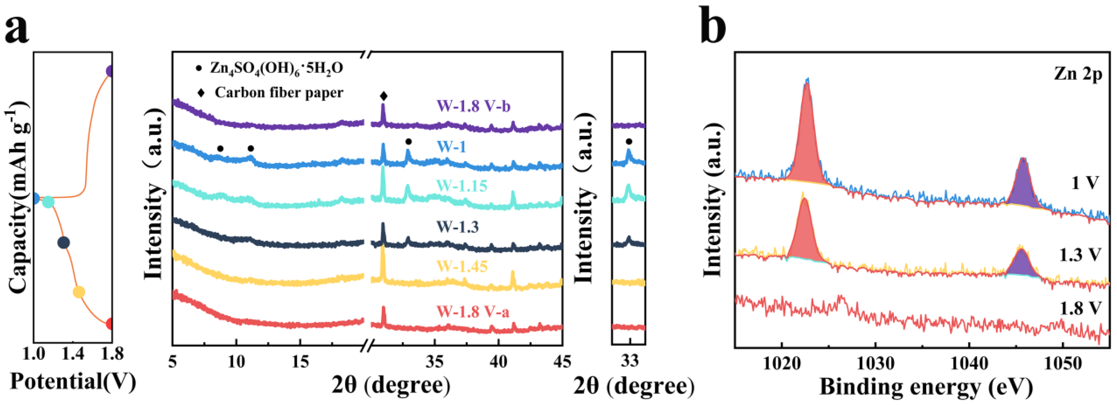
To explore the effect of the CEI layer on the mechanism of energy storage, the structure evolution of the W-MnO2 cathode was analyzed by means of ex situ XRD, XPS, and TEM. Taking into account the BET result of δ-MnO2 and the morphology change of the W-MnO2 cathode, the storage mechanism was analyzed through bulk diffusion rather than surface adsorption. The ex situ XRD of the W-MnO2 cathode (Figure 3a) reveals the incremental increase of characteristic peaks (around 10° and 33°) corresponding to Zn4SO4(OH)6·xH2O upon the entire discharge process, which evidences the occurrence of H+ insertion. This is consistent with the findings of previous research [47,48,49,50]. In addition, the formation of Zn4SO4(OH)6·xH2O nanosheet at the discharge stage is revealed by ex situ TEM (Figure S7). The results of TEM mapping show the presence of S, Zn, and O elements. Moreover, it can be seen from the SAED pattern (Figure S7) that the nanosheet is Zn4SO4(OH)6·xH2O. In contrast, H+ is gradually released from the W-MnO2 cathode during the subsequent charge to 1.8 V, which is accompanied by the disappearance of Zn4SO4(OH)6·xH2O, as shown in Figure 3c. That is to say, reversible (de)insertion occurs to H+ throughout the storage process. The reversible storage of Zn2+ in the W-MnO2 host is confirmed by the ex situ XPS performed on the acid-washed cathodes (Figure 3b). When the cathode is discharged to 1.3 V, there are two strong peaks emerging at 1045.8 and 1022.7 eV, which can be considered evidence of Zn2+ intercalation [51,52]. The peak strength of the Zn 2p further increases when the cathode is fully discharged (1 V), indicating the occurrence of Zn2+ intercalation throughout the discharge process. In addition, the stability of the MnWO4 CEI film during the cycle process is indicated by TEM, HRTEM, and corresponding SAED (Figure S8) in full charge and discharge states. Therefore, H+/Zn2+ co-insertion is confirmed as the storage mechanism of the W-MnO2 cathode during the discharge process.
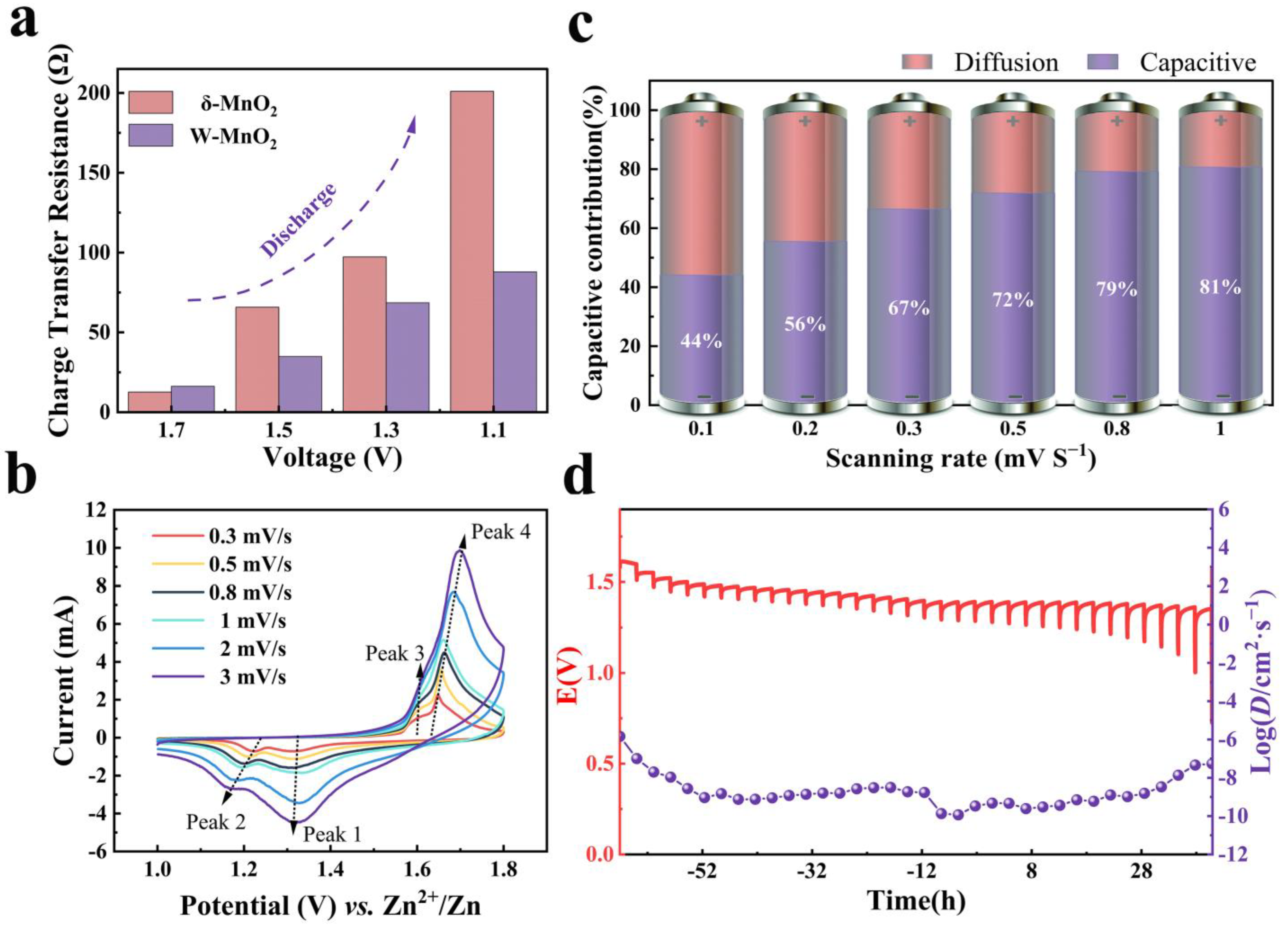
When the mechanism of energy storage is investigated, the reversible formation of the by-product (Zn4SO4(OH)6·xH2O) on the cathode is worth noting. During the discharge process, the formation of Zn4SO4(OH)6·xH2O nanosheets could inhibit the electrochemical reaction in the cathode to some extent, as reported in other studies [34]. To demonstrate the impact of the by-product (Zn4SO4(OH)6·xH2O) on the charge transfer resistance, the EIS test was performed during the discharge process. The EIS data (Figure S9) of the W-MnO2 cathode were fitted with the equivalent circuit template, as indicated by two semicircles in the medium and high-frequency regions. The semicircle at a high frequency is considered as the constructed MnWO4 CEI layer and the Zn4SO4(OH)6·xH2O formed during the discharge process, while that at a medium frequency is attributed to the charge transfer resistance (Rct). Figure 4a shows the variation and comparison of the Rct during different stages of discharge for both W-MnO2 and δ-MnO2 cathodes. Apparently, the Rct of δ-MnO2 cathode increases rapidly (from 12.62 to 201 Ω), which suggests that the existence of Zn4SO4(OH)6·xH2O nanosheet plays a part in insulating the active material, which impedes electron transport and increases internal resistance. For the W-MnO2 cathode, the incremental of Rct is more significant compared to the δ-MnO2 cathode, indicating that the impact of Zn4SO4(OH)6·xH2O is mitigated by the presence of the MnWO4 CEI layer. Moreover, the Rct of the W-MnO2 cathode is higher than that of the δ-MnO2 cathode in the initial state, which is due to the relatively low conductivity of the MnWO4 CEI layer.
To reveal the effect of the MnWO4 CEI layer and Zn4SO4(OH)6·xH2O intermediate on the reaction kinetics of the W-MnO2 cathode, the kinetics behaviors were analyzed by carrying out CV (cyclic voltammetric curve) tests at varying scan rates (0.3 to 3.0 mV s−1), as shown in Figure 4b. For the W-MnO2 cathode, the b-value (Figure S11a) of the three different peaks is calculated to be 0.80, 0.58, and 0.62 for peaks 1, 2, and 4, respectively. As for δ-MnO2 cathode (Figures S10 and S11b), the b-value of peaks 1, 2, and 4 is 0.6, 0.41, and 0.53, respectively. The rise in the b-value of the W-MnO2 cathode indicates that the improvement of reaction kinetics contributes to an excellent rate performance [53]. Furthermore, the capacitive-controlled contribution for the W-MnO2 cathode is calculated to be 44.1%, 55.5%, 66.5%, 71.9%, 79.2%, and 80.7% at a scan rate of 0.1, 0.2, 0.3, 0.5, 0.8, and 1 mV s−1, respectively (Figure 4c). The proportion of capacitive contribution to the whole capacity for the W-MnO2 cathode at 1 mV s−1 is 80.7%, suggesting that the pseudocapacitive behavior dominates the storage mechanism. Compared with the δ-MnO2 cathode, the capacitive contributions of the δ-MnO2 cathode (Figure S12) is less significant at different scan rates, which reaffirms the improvement of reaction kinetics by the construction of the MnWO4 CEI layer. Finally, to gain an insight into the diffusion dynamics, the galvanostatic intermittent titration technique (GITT) was applied to calculate the diffusion coefficient (D) at different stages of discharge (Figure 4d and Figure S13). It can be found that the W-MnO2 and δ-MnO2 cathodes experience two stages of discharge according to the D value. In the first one, D is between 10−8 and 10−9. In the second one, D decreases to the range of 10−9–10−10. It is noteworthy that the MnWO4 CEI layer causes the diffusion coefficient of the W-MnO2 cathode to be relatively more stable, which is always above 10−10. To sum up, the MnWO4 CEI layer of δ-MnO2 can mitigate the impact of Zn4SO4(OH)6·xH2O on the cathode and ensure sufficient reaction kinetics, which explains the better electrochemical performance.

4. Conclusions

In the present study, a MnWO4 CEI layer was constructed on the δ-MnO2 surface by following a facile cyclic voltammetry method, which significantly reduced the impact of by-product (Zn4SO4(OH)6·xH2O) on the cathode and improved the reaction kinetics during the process of H+/Zn2+ co-intercalation, thus enhancing the rate performance (295.2 mA at 0.1 A g−1 and 105.5 mA at 10 A g−1). More importantly, the dissolution of Mn was inhibited in the AZIBs by the MnWO4 CEI layer, thus ensuring its long cycling lifespan. Compared to the activated capacity at 500 cycles, the capacity retention rate at 10 A g−1 was maintained at 98.2% after 2000 cycles, which is much higher than the retention rate of 33.4% for the pristine MnO2 cathode. This CEI construction strategy could contribute to exploring the stable Mn-based cathode of AZIBS.

Supplementary Materials

The following supporting information can be downloaded at: https://www.mdpi.com/article/10.3390/ma16083228/s1, Figure S1: XRD pattern of synthetic δ-MnO2 pristine powder; Figure S2: N2 adsorption isotherms of δ-MnO2; Figure S3: CV curves of the δ-MnO2 electrode at 1 mV/s; Figure S4: Galvanostatic charge and discharge curves of the δ-MnO2 cathode at 0.2 A g−1; Figure S5: Galvanostatic charge and discharge curves of W-MnO2 cathode at various current densities ranging from 0.2 A g−1 to 10 A g−1; Figure S6: Galvanostatic charge and discharge curves of the δ-MnO2 cathode at various current densities ranging from 0.2 A g−1 to 10 A g−1; Figure S7: High-angle annular bright-field scanning TEM (HAABF-STEM) image and the corresponding elemental mappings, respectively; Figure S8: (a,b) TEM, HR-TEM and SAED pattern of W-MnO2: (a,c) charged (1.8 V). (b,d) discharged (1 V); Figure S9: EIS of (a) the W-MnO2 and (b) δ-MnO2 cathodes at different stages during the discharge process. The equivalent circuit model for (c) the W-MnO2 and d) the δ-MnO2 electrode; Figure S10: CV tests for δ-MnO2 cathode at various scan rates ranging from 0.3 to 3 mV/s; Figure S11: (a,b) b values of different peaks in CV curves for W-MnO2 and δ-MnO2 cathodes: (a) W-MnO2. (b) δ-MnO2; Figure S12: The proportion of capacitive and diffusion contributions at various scan rates for δ-MnO2; Figure S13: GITT test of the δ-MnO2 cathode; Table S1: Comparison of cycling performance with other recent studies [31,32,33,34,35,36,37].

Author Contributions

Conceptualization, H.T. and S.C.; methodology, H.Z. (Huanlin Zhang), Y.Z. and X.S.; software, L.L. and T.M.; validation, H.T., H.Z. (Hang Zhang) and Y.Z.; investigation, H.T. and Y.Z.; resources, X.S. and S.C.; data curation, H.T.; writing—original draft preparation, H.T.; writing—review and editing, S.C.; supervision, S.C.; funding acquisition, S.C. All authors have read and agreed to the published version of the manuscript.

Funding

This research was funded by the National Natural Science Foundation of China (Nos. 51872197 and 52271246). This study was additionally funded by Tianjin Research Innovation Project for Postgraduate Students (Project No. 2021YJSB171).

Institutional Review Board Statement

Not applicable.

Informed Consent Statement

Not applicable.

Data Availability Statement

The data presented in this study are available on request from the corresponding author.

Conflicts of Interest

The authors declare no conflict of interest.

References

  1. Macrelli, A.; Olivieri, M.; Lamperti, A.; Russo, V.; Bozzini, B.; Menegazzo, M.; Bussetti, G.; Casari, C.S.; Li Bassi, A. Nanostructured ZnxMn3−xO4 thin films by pulsed laser deposition: A spectroscopic and electrochemical study towards the application in aqueous Zn-ion batteries. Electrochim. Acta 2023, 442, 141909. [Google Scholar] [CrossRef]
  2. Zampardi, G.; La Mantia, F. Prussian blue analogues as aqueous Zn-ion batteries electrodes: Current challenges and future perspectives. Curr. Opin. Electrochem. 2020, 21, 84–92. [Google Scholar] [CrossRef]
  3. Liu, Z.; Qin, L.; Cao, X.; Zhou, J.; Pan, A.; Fang, G.; Wang, S.; Liang, S. Ion migration and defect effect of electrode materials in multivalent-ion batteries. Prog. Mater. Sci. 2022, 125, 100911. [Google Scholar] [CrossRef]
  4. Tang, B.; Fang, G.; Zhou, J.; Wang, L.; Lei, Y.; Wang, C.; Lin, T.; Tang, Y.; Liang, S. Potassium vanadates with stable structure and fast ion diffusion channel as cathode for rechargeable aqueous zinc-ion batteries. Nano Energy 2018, 51, 579–587. [Google Scholar] [CrossRef]
  5. Chen, D.; Lu, M.; Cai, D.; Yang, H.; Han, W. Recent advances in energy storage mechanism of aqueous zinc-ion batteries. J. Energy Chem. 2021, 54, 712–726. [Google Scholar] [CrossRef]
  6. Song, M.; Tan, H.; Chao, D.; Fan, H.J. Recent advances in Zn-ion batteries. Adv. Funct. Mater. 2018, 28, 1802564. [Google Scholar] [CrossRef]
  7. Fegade, U.; Jethave, G.; Khan, F.; Al Ahmed, A.; Karmouch, R.; Shariq, M.; Inamuddin; Ahmer, M.F. Recent development of aqueous zinc-ion battery cathodes and future challenges: Review. Int. J. Energ. Res. 2022, 46, 13152–13177. [Google Scholar] [CrossRef]
  8. Liu, S.; Sun, Y.; Yang, J.; Zhang, Y.; Cai, Z. Highly loaded and binder-free molybdenum trioxide cathode material prepared using multi-arc ion plating for aqueous zinc ion batteries. Materials 2022, 15, 5954. [Google Scholar] [CrossRef]
  9. Li, T.; Li, H.; Yuan, J.; Xia, Y.; Liu, Y.; Sun, A. Recent advance and modification strategies of transition metal dichalcogenides (TMDs) in aqueous zinc ion batteries. Materials 2022, 15, 2654. [Google Scholar] [CrossRef]
  10. Karapidakis, E.; Vernardou, D. Progress on V2O5 cathodes for multivalent aqueous batteries. Materials 2021, 14, 2310. [Google Scholar] [CrossRef]
  11. Wang, D.; Wang, L.; Liang, G.; Li, H.; Liu, Z.; Tang, Z.; Liang, J.; Zhi, C. A Superior δ-MnO2 cathode and a self-healing Zn-δ-MnO2 battery. ACS Nano 2019, 13, 10643–10652. [Google Scholar] [CrossRef]
  12. Alfaruqi, M.H.; Islam, S.; Mathew, V.; Song, J.; Kim, S.; Tung, D.P.; Jo, J.; Kim, S.; Baboo, J.P.; Xiu, Z.; et al. Ambient redox synthesis of vanadium-doped manganese dioxide nanoparticles and their enhanced zinc storage properties. Appl. Surf. Sci. 2017, 404, 435–442. [Google Scholar] [CrossRef]
  13. Chamoun, M.; Brant, W.R.; Tai, C.; Karlsson, G.; Noréus, D. Rechargeability of aqueous sulfate Zn/MnO2 batteries enhanced by accessible Mn2+ ions. Energy Storage Mater. 2018, 15, 351–360. [Google Scholar] [CrossRef]
  14. Zuo, Y.; Meng, T.; Tian, H.; Ling, L.; Zhang, H.; Zhang, H.; Sun, X.; Cai, S. Enhanced H+ storage of a MnO2 cathode via a MnO2 nanolayer interphase transformed from manganese phosphate. ACS Nano 2023, 17, 5600–5608. [Google Scholar] [CrossRef]
  15. Sun, W.; Wang, F.; Hou, S.; Yang, C.; Fan, X.; Ma, Z.; Gao, T.; Han, F.; Hu, R.; Zhu, M.; et al. Zn/MnO2 battery chemistry with H+ and Zn2+ coinsertion. J. Am. Chem. Soc. 2017, 139, 9775–9778. [Google Scholar] [CrossRef]
  16. Kundu, D.; Adams, B.D.; Duffort, V.; Vajargah, S.H.; Nazar, L.F. A high-capacity and long-life aqueous rechargeable zinc battery using a metal oxide intercalation cathode. Nat. Energy 2016, 1, 16119. [Google Scholar] [CrossRef]
  17. Chen, J.; Xiao, B.; Hu, C.; Chen, H.; Huang, J.; Yan, D.; Peng, S. Construction strategy of VO2 @V2C 1D/2D heterostructure and improvement of zinc-ion diffusion ability in VO2 (B). ACS Appl. Mater. Inter. 2022, 14, 28760–28768. [Google Scholar] [CrossRef]
  18. Dong, Y.; Jia, M.; Wang, Y.; Xu, J.; Liu, Y.; Jiao, L.; Zhang, N. Long-life zinc/vanadium pentoxide battery enabled by a concentrated aqueous ZnSO4 electrolyte with proton and zinc ion co-intercalation. ACS Appl. Energ. Mater. 2020, 3, 11183–11192. [Google Scholar] [CrossRef]
  19. Zhang, N.; Dong, Y.; Jia, M.; Bian, X.; Wang, Y.; Qiu, M.; Xu, J.; Liu, Y.; Jiao, L.; Cheng, F. Rechargeable aqueous Zn-V2O5 battery with high energy density and long cycle life. ACS Energy Lett. 2018, 3, 1366–1372. [Google Scholar] [CrossRef]
  20. Chen, L.; Ruan, Y.; Zhang, G.; Wei, Q.; Jiang, Y.; Xiong, T.; He, P.; Yang, W.; Yan, M.; An, Q.; et al. Ultrastable and high-performance Zn/VO2 battery based on a reversible single-phase reaction. Chem. Mater. 2019, 31, 699–706. [Google Scholar] [CrossRef]
  21. Lu, K.; Song, B.; Zhang, J.; Ma, H. A rechargeable Na-Zn hybrid aqueous battery fabricated with nickel hexacyanoferrate and nanostructured zinc. J. Power Sources 2016, 321, 257–263. [Google Scholar] [CrossRef]
  22. Yang, Q.; Mo, F.; Liu, Z.; Ma, L.; Li, X.; Fang, D.; Chen, S.; Zhang, S.; Zhi, C. Activating C-coordinated iron of iron hexacyanoferrate for Zn hybrid-ion batteries with 10,000-cycle lifespan and superior rate capability. Adv. Mater. 2019, 31, 1901521. [Google Scholar] [CrossRef] [PubMed]
  23. Yi, H.; Qin, R.; Ding, S.; Wang, Y.; Li, S.; Zhao, Q.; Pan, F. Structure and properties of Prussian blue analogues in energy storage and conversion applications. Adv. Funct. Mater. 2021, 31, 2006970. [Google Scholar] [CrossRef]
  24. Zhang, L.; Chen, L.; Zhou, X.; Liu, Z. Towards high-voltage aqueous metal-ion batteries beyond 1.5 V: The zinc/zinc hexacyanoferrate system. Adv. Energy Mater. 2015, 5, 1400930. [Google Scholar] [CrossRef]
  25. Zhao, Y.; Zhu, Y.; Zhang, X. Challenges and perspectives for manganese-based oxides for advanced aqueous zinc-ion batteries. Infomat 2020, 2, 237–260. [Google Scholar] [CrossRef]
  26. Ren, Q.; Yuan, Y.; Wang, S. Interfacial strategies for suppression of Mn dissolution in rechargeable battery cathode materials. ACS Appl. Mater. Inter. 2022, 14, 23022–23032. [Google Scholar] [CrossRef]
  27. Fang, G.; Zhu, C.; Chen, M.; Zhou, J.; Tang, B.; Cao, X.; Zheng, X.; Pan, A.; Liang, S. Suppressing manganese dissolution in potassium manganate with rich oxygen defects engaged high-energy-density and durable aqueous zinc-ion battery. Adv. Funct. Mater. 2019, 29, 1808375. [Google Scholar] [CrossRef]
  28. Poyraz, A.S.; Laughlin, J.; Zec, Z. Improving the cycle life of cryptomelane type manganese dioxides in aqueous rechargeable zinc ion batteries: The effect of electrolyte concentration. Electrochim. Acta 2019, 305, 423–432. [Google Scholar] [CrossRef]
  29. Zhou, M.; Chen, Y.; Fang, G.; Liang, S. Electrolyte/electrode interfacial electrochemical behaviors and optimization strategies in aqueous zinc-ion batteries. Energy Storage Mater. 2022, 45, 618–646. [Google Scholar] [CrossRef]
  30. Verma, V.; Kumar, S.; Manalastas, W.; Srinivasan, M. Undesired reactions in aqueous rechargeable zinc ion batteries. ACS Energy Lett. 2021, 6, 1773–1785. [Google Scholar] [CrossRef]
  31. Guo, S.; Liang, S.; Zhang, B.; Fang, G.; Ma, D.; Zhou, J. Cathode interfacial layer formation via in situ electrochemically charging in aqueous zinc-ion battery. ACS Nano 2019, 13, 13456–13464. [Google Scholar] [CrossRef]
  32. Luo, S.; Cao, X.; Su, Q.; Zhang, Y.; Liu, S.; Xie, X.; Liang, S.; Pan, A. Layered barium vanadate cathodes for aqueous zinc batteries: Enhancing cycling stability through inhibition of vanadium dissolution. ACS Appl. Energ. Mater. 2021, 4, 6197–6204. [Google Scholar] [CrossRef]
  33. Wu, B.; Zhang, G.; Yan, M.; Xiong, T.; He, P.; He, L.; Xu, X.; Mai, L. Graphene scroll-coated α-MnO2 nanowires as high-performance cathode materials for aqueous Zn-ion battery. Small 2018, 14, 1703850. [Google Scholar] [CrossRef]
  34. Guo, J.; Ming, J.; Lei, Y.; Zhang, W.; Xia, C.; Cui, Y.; Alshareef, H.N. Artificial solid electrolyte interphase for suppressing surface reactions and cathode dissolution in aqueous zinc ion batteries. ACS Energy Lett. 2019, 4, 2776–2781. [Google Scholar] [CrossRef]
  35. Li, S.; Yu, D.; Liu, L.; Yao, S.; Wang, X.; Jin, X.; Zhang, D.; Du, F. In-situ electrochemical induced artificial solid electrolyte interphase for MnO@C nanocomposite enabling long-lived aqueous zinc-ion batteries. Chem. Eng. J. 2022, 430, 132673. [Google Scholar] [CrossRef]
  36. Liu, Y.; Zhi, J.; Hoang, T.K.A.; Zhou, M.; Han, M.; Wu, Y.; Shi, Q.; Xing, R.; Chen, P. Paraffin Based cathode-electrolyte interface for highly reversible aqueous zinc-ion battery. ACS Appl. Energ. Mater. 2022, 5, 4840–4849. [Google Scholar] [CrossRef]
  37. Zhang, L.; Zhang, B.; Hu, J.; Liu, J.; Miao, L.; Jiang, J. An in situ artificial cathode electrolyte interphase strategy for suppressing cathode dissolution in aqueous zinc ion batteries. Small Methods 2021, 5, 2100094. [Google Scholar] [CrossRef]
  38. Chen, X.; Cao, Z.; Xing, L.; Liao, Y.; Qiu, Y.; Li, W. Improved Li-storage performance with PEDOT-decorated MnO2 nanoboxes. Nanoscale 2017, 9, 18467–18473. [Google Scholar] [CrossRef]
  39. Guo, C.; Zhou, Q.; Liu, H.; Tian, S.; Chen, B.; Zhao, J.; Li, J. A case study of β- and δ-MnO2 with different crystallographic forms on ion-storage in rechargeable aqueous zinc ion battery. Electrochim. Acta 2019, 324, 134867. [Google Scholar] [CrossRef]
  40. Wu, P.; Dai, S.; Chen, G.; Zhao, S.; Xu, Z.; Fu, M.; Chen, P.; Chen, Q.; Jin, X.; Qiu, Y.; et al. Interfacial effects in hierarchically porous α-MnO2/Mn3O4 heterostructures promote photocatalytic oxidation activity. Appl. Catal. B Environ. 2020, 268, 118418. [Google Scholar] [CrossRef]
  41. Puttaswamy, R.; Nagaraj, R.; Kulkarni, P.; Beere, H.K.; Upadhyay, S.N.; Balakrishna, R.G.; Sanna Kotrappanavar, N.; Pakhira, S.; Ghosh, D. Constructing a high-performance aqueous rechargeable zinc-ion battery cathode with self-assembled mat-like packing of intertwined Ag(I) pre-inserted V3O7·H2O microbelts with reduced graphene oxide core. ACS Sustain. Chem. Eng. 2021, 9, 3985–3995. [Google Scholar] [CrossRef]
  42. Cook, J.B.; Kim, H.S.; Yan, Y.; Ko, J.S.; Robbennolt, S.; Dunn, B.; Tolbert, S.H. Mesoporous MoS2 as a transition metal dichalcogenide exhibiting pseudocapacitive Li and Na-ion charge storage. Adv. Energy Mater. 2016, 6, 1501937. [Google Scholar] [CrossRef]
  43. Deiss, E. Spurious chemical diffusion coefficients of Li+ in electrode materials evaluated with GITT. Electrochim. Acta 2005, 50, 2927–2932. [Google Scholar] [CrossRef]
  44. Chen, W.; Li, G.; Pei, A.; Li, Y.; Liao, L.; Wang, H.; Wan, J.; Liang, Z.; Chen, G.; Zhang, H.; et al. A manganese-hydrogen battery with potential for grid-scale energy storage. Nat. Energy 2018, 3, 428–435. [Google Scholar] [CrossRef]
  45. Ilton, E.S.; Post, J.E.; Heaney, P.J.; Ling, F.T.; Kerisit, S.N. XPS determination of Mn oxidation states in Mn (hydr)oxides. Appl. Surf. Sci. 2016, 366, 475–485. [Google Scholar] [CrossRef]
  46. Gao, X.; Wu, H.; Li, W.; Tian, Y.; Zhang, Y.; Wu, H.; Yang, L.; Zou, G.; Hou, H.; Ji, X. H+-insertion boosted α-MnO2 for an Aqueous Zn-ion battery. Small 2020, 16, 1905842. [Google Scholar] [CrossRef]
  47. Pan, H.; Shao, Y.; Yan, P.; Cheng, Y.; Han, K.S.; Nie, Z.; Wang, C.; Yang, J.; Li, X.; Bhattacharya, P.; et al. Reversible aqueous zinc/manganese oxide energy storage from conversion reactions. Nat. Energy 2016, 1, 16039. [Google Scholar] [CrossRef]
  48. Liu, N.; Wu, X.; Fan, L.; Gong, S.; Guo, Z.; Chen, A.; Zhao, C.; Mao, Y.; Zhang, N.; Sun, K. Intercalation pseudocapacitive Zn2+ storage with hydrated vanadium dioxide toward ultrahigh rate performance. Adv. Mater. 2020, 32, 1908420. [Google Scholar] [CrossRef]
  49. Zhang, R.; Liang, P.; Yang, H.; Min, H.; Niu, M.; Jin, S.; Jiang, Y.; Pan, Z.; Yan, J.; Shen, X.; et al. Manipulating intercalation-extraction mechanisms in structurally modulated δ-MnO2 nanowires for high-performance aqueous zinc-ion batteries. Chem. Eng. J. 2022, 433, 133687. [Google Scholar] [CrossRef]
  50. Zuo, Y.; Liu, P.; Ling, L.; Tian, M.; Wang, Z.; Tian, H.; Meng, T.; Sun, X.; Cai, S. Boosted H+ intercalation enables ultrahigh rate performance of the δ-MnO2 cathode for aqueous zinc batteries. ACS Appl. Mater. Inter. 2022, 14, 26653–26661. [Google Scholar] [CrossRef]
  51. Pang, Q.; Sun, C.; Yu, Y.; Zhao, K.; Zhang, Z.; Voyles, P.M.; Chen, G.; Wei, Y.; Wang, X. H2V3O8 nanowire/graphene electrodes for aqueous rechargeable zinc ion batteries with high rate capability and large capacity. Adv. Energy Mater. 2018, 8, 1800144. [Google Scholar] [CrossRef]
  52. Wang, X.; Xi, B.; Ma, X.; Feng, Z.; Jia, Y.; Feng, J.; Qian, Y.; Xiong, S. Boosting zinc-ion storage capability by effectively suppressing vanadium dissolution based on robust layered barium vanadate. Nano Lett. 2020, 20, 2899–2906. [Google Scholar] [CrossRef]
  53. Cook, J.B.; Kim, H.S.; Lin, T.C.; Lai, C.H.; Dunn, B.; Tolbert, S.H. Pseudocapacitive charge storage in thick composite MoS2 Nanocrystal-based electrodes. Adv. Energy Mater. 2017, 7, 1601283. [Google Scholar] [CrossRef]
Figure 1. (a) Schematic illustration of the preparation process of MnWO4 CEI layer. (b) XRD patterns of δ-MnO2 and W-MnO2. (c) High-resolution XPS spectra of Mn 3s region in δ-MnO2 and W-MnO2. (d,e) The morphology of (d) δ-MnO2 and (e) W-MnO2. (f) TEM image and the elemental mappings of W-MnO2. (g) HRTEM image of MnWO4 on the surface of W-MnO2 and the corresponding SAED pattern (inset).
Materials 16 03228 g001
Figure 2. Electrochemical performance of δ-MnO2 and W-MnO2 cathodes. (a) CV curves of W-MnO2 cathode at 1 mV s−1. (b,c) Galvanostatic charge and discharge curves of the W-MnO2 cathode and corresponding cycling performance at 0.2 A g−1. (d) Rate capacity of δ-MnO2 and W-MnO2 cathodes with current density from 0.2 to 10 A g−1. (e) Cycling performance at 10 A g−1.
Materials 16 03228 g002
Figure 3. (a) Ex situ XRD analysis of W-MnO2 cathode at various voltages. (b) XPS spectra of Zn 2p at different discharge stages.
Materials 16 03228 g003
Figure 4. (a) The charge transfer resistance of W-MnO2 and δ-MnO2 cathodes at the discharge stage. (b) CV tests at various scan rates from 0.3 to 3 mV s−1. (c) The proportion of capacitive contributions at different scan rates for W-MnO2. (d) GITT curves of the W-MnO2 cathode after activation during the discharge process.
Materials 16 03228 g004
Disclaimer/Publisher’s Note: The statements, opinions and data contained in all publications are solely those of the individual author(s) and contributor(s) and not of MDPI and/or the editor(s). MDPI and/or the editor(s) disclaim responsibility for any injury to people or property resulting from any ideas, methods, instructions or products referred to in the content.