
Modeling of Reactive Sputtering—History and Development


Abstract
:1. Introduction
- Reactive sputtering of the M-target in the Ar + X2 environment. The method produces a film of stoichiometric composition;
- Sputtering of the MmXn target in the Ar + X2 environment. The method also leads to a stoichiometric film;
- Sputtering of the MmXn target in the Ar environment. Due to the preferential sputtering of the light component X2, the surface layer of the target is reduced from MmXn to MXx, which allows the depositing of films of intermediate composition.
- The target is free from reaction products;
- Metal is sputtered from the target surface. The sputtering rate is high, and the ion-induced electron emission yield is not high;
- The reactive gas adsorbs on the target, the inner surfaces of the vacuum chamber, on which atoms of the sputtered metal are deposited, and is pumped out;
- Current–voltage (I–V) characteristic of the discharge corresponds to the discharge in pure argon.
- The target surface is completely covered by the MmXn compound;
- MmXn molecules are sputtered from the target surface. The sputtering rate is low, and the ion-induced electron emission yield is high;
- The target consumes an insignificant part of the reactive gas to maintain the steady state, the rest of the gas is pumped out by a vacuum pump;
- The I-V characteristics of the discharge differ from that of the metallic mode—the direction and magnitude of the changes depend on the material of a target and the type of reactive gas.
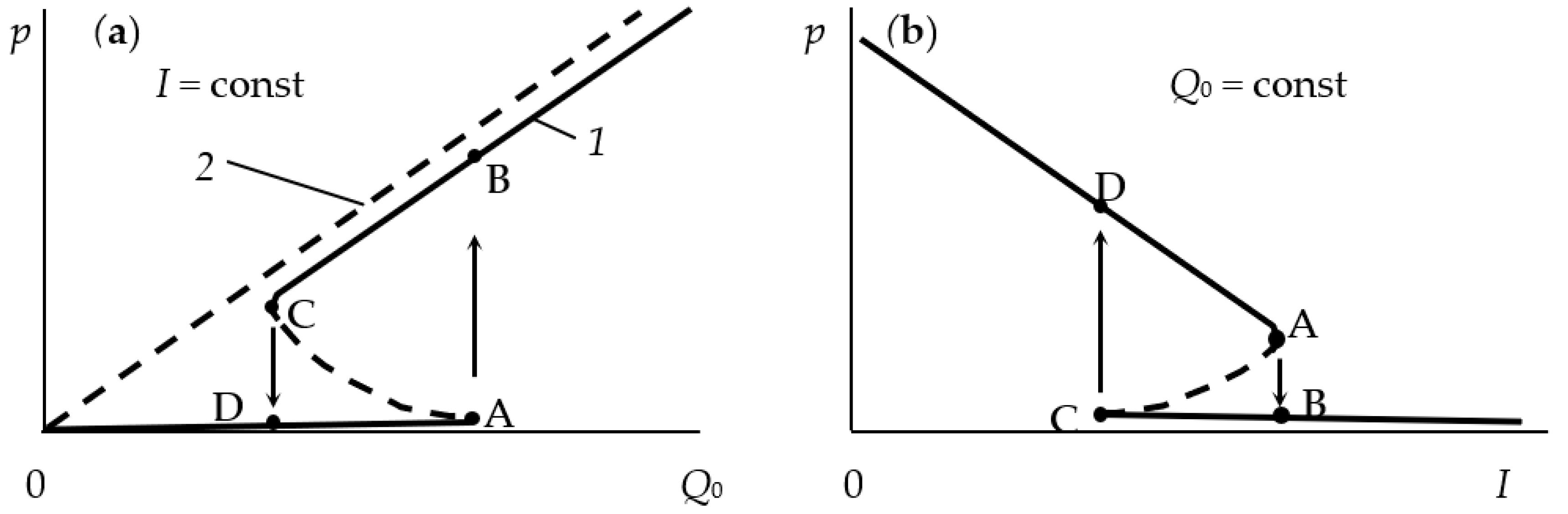
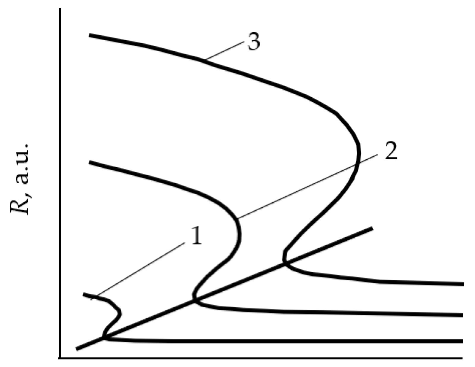
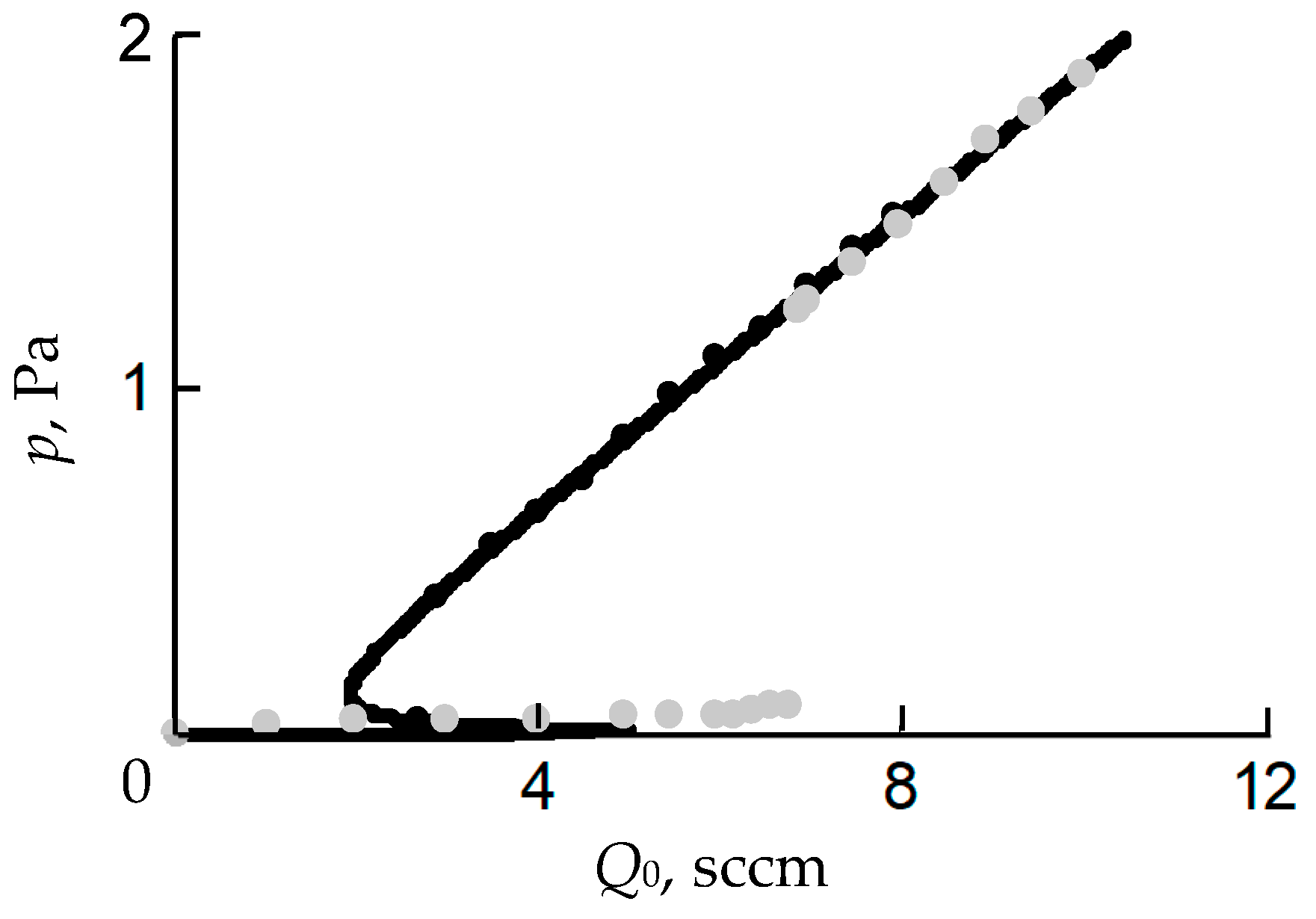
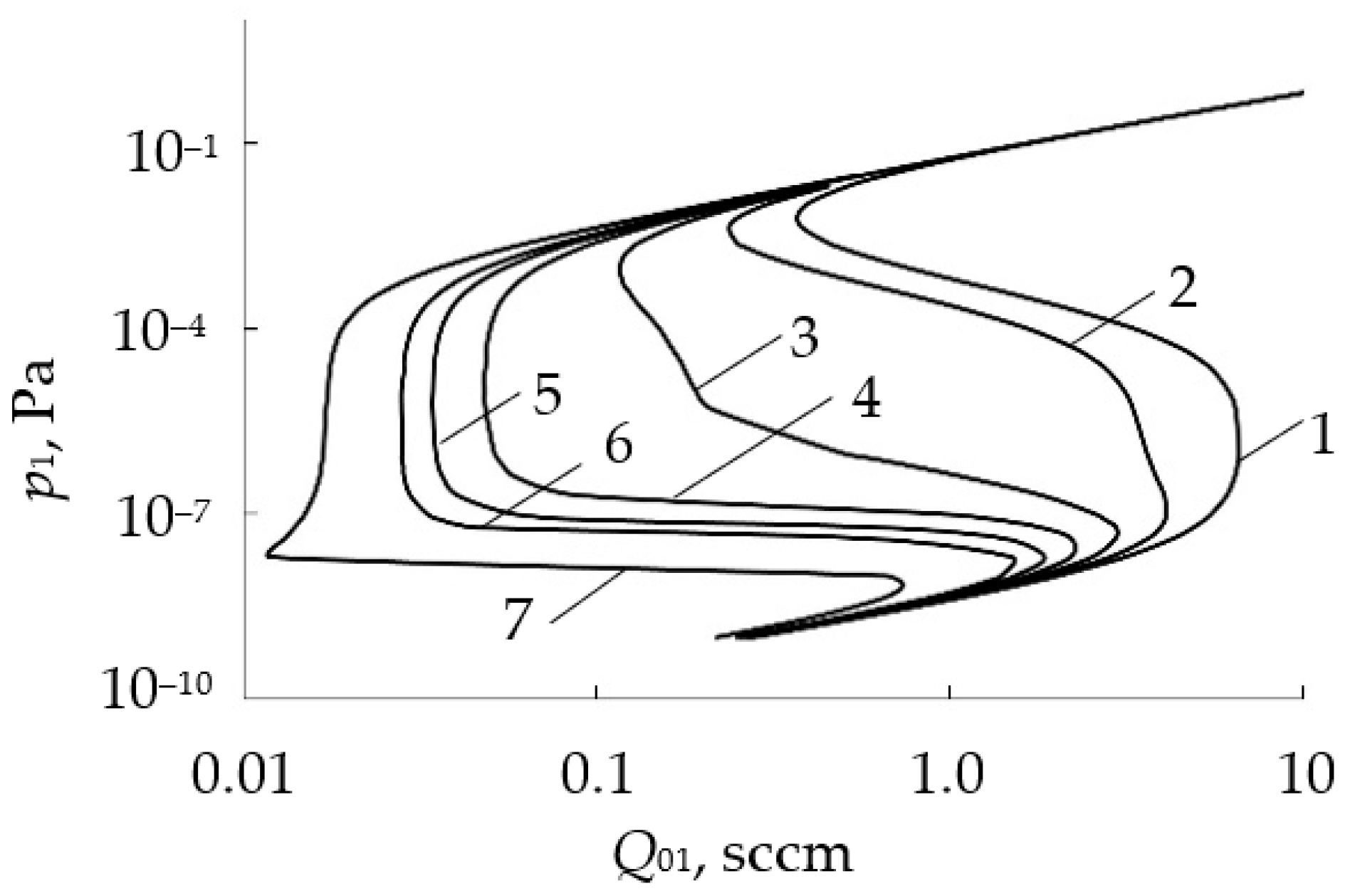
- In the initial section 0A on curve 1, the value of p is close to zero (the total pressure of the gas mixture is equal to the partial pressure of argon);
- As Q0 increases to point A, a noticeable change in p is not observed;
- When point A is reached, the process avalanches into a new steady state (point B);
- With a further increase in Q0, the pressure p grows in proportion to Q0, but for any Q0 it is always less than the value measured in the absence of a discharge (curve 2 in Figure 1a);
- As Q0 decreases to point C, a proportional decrease in p is observed;
- When point C is reached, the process returns like an avalanche to the initial steady state (point D).
2. Specific Isothermal Models
- Two processes compete on the excited target surface: the formation of a thin layer of metal compound with reactive gas and sputtering of this layer by accelerated argon ions;
- On the substrate and walls of the vacuum chamber, the sputtering target material is deposited, and the reactive gas molecules are chemisorbed.
- Chemisorption of neutral reactive gas molecules (which can occur without a glow discharge);
- Covering the target with ions and atoms of reactive gas, which are activated by a glow discharge. This process is called by the authors “ion plating”.
- The partial pressure of the reactive gas and the film deposition rate are determined by the degree of coverage of the target surface with the MmXn film;
- Chemisorption was adopted as the mechanism of the MmXn film formation on the target surface;
- The process is considered isothermal in the sense that the gas environment and all internal surfaces of the vacuum chamber have the same temperature;
- The model equations describe only the process on the target; there is no separate equation for the chamber wall and the balance equation for gas particles.
3. General Isothermal Chemisorption Model (the Berg Model)
3.1. Initial Model
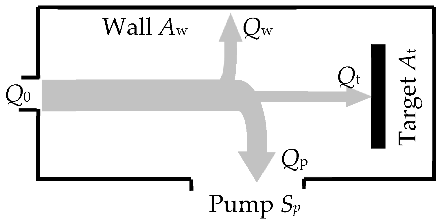
- The model should take into account the processes occurring on the surfaces of the target and the wall of the vacuum chamber with areas At and Aw, respectively (the area of the substrate As was included in Aw due to its insignificance);
- The sputtering process occurs under isothermal conditions. This means that the target and the wall have the same temperature, T, which is equal to the temperature of the gas environment;
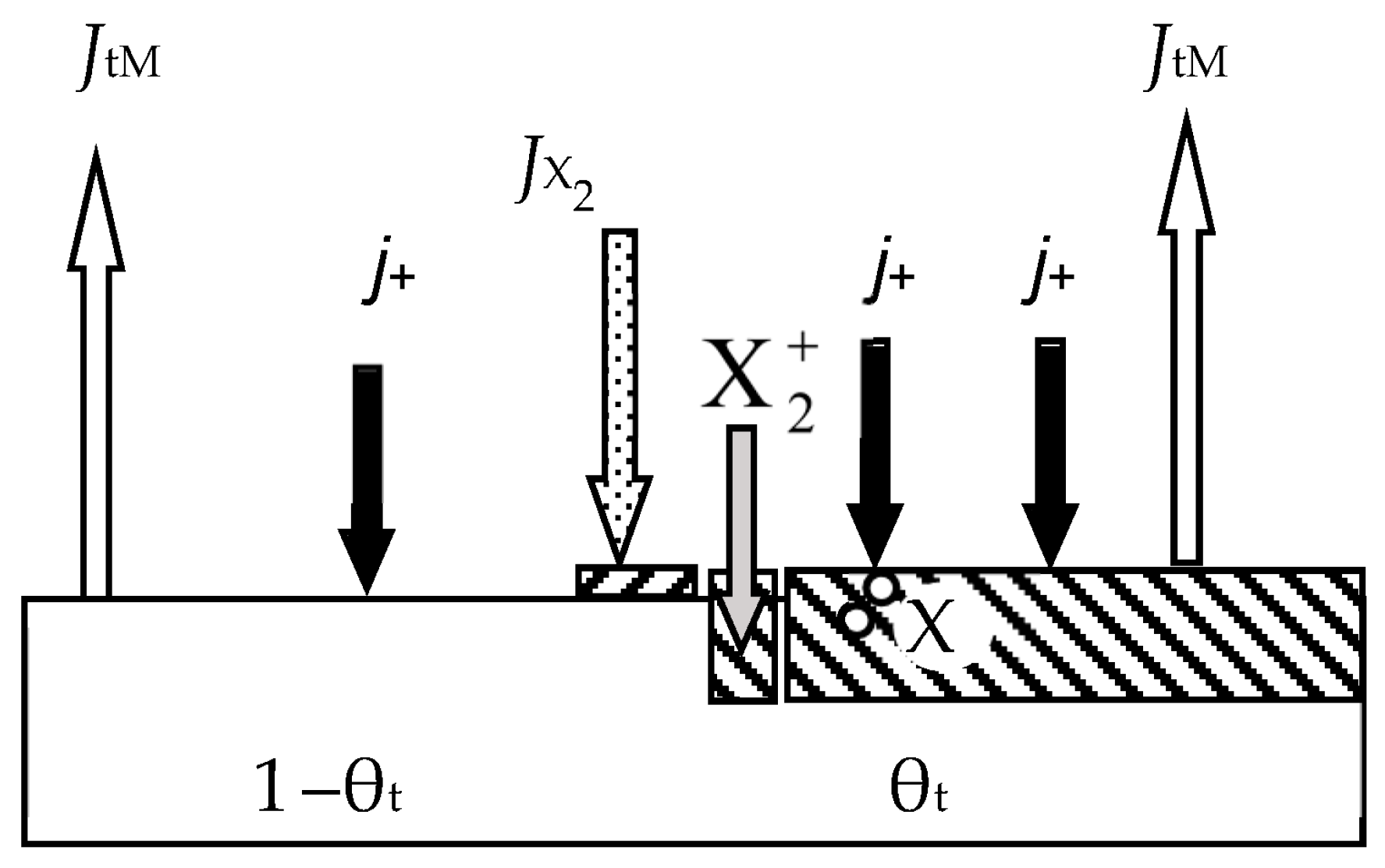
- Two processes compete on the target surface:
- Formation of the MmXn compound due to chemisorption with the kinetics (dθt/dt)chem (see Figure 2). Quantitatively, it is characterized by the sticking coefficient α, which specifies the fraction of the adsorbed gas flow with density JX2 incident on the surface (in Formulas (3) and (5)–(7), this value is denoted by F):where pX2 and mX2 are the partial pressure and mass of a reactive gas molecule, respectively;
- Sputtering of the MmXn compound by argon ions with kinetics (dθt/dt)sp.
- Chemisorption on surfaces covered by the MmXn compound is negligible;
- Sputtering of the MmXn compound from the target surface occurs in the form of molecules that are deposited on the walls of the chamber;
- The process has two independent variables: the discharge current density of argon ions on the target j and the Q0 reactive gas incoming flow (the flow introduced into the vacuum chamber).
3.2. Development of the Model
- Two processes compete on the target surface:
- Formation of the MO + MN compound due to chemisorption. The process was quantitatively characterized by the sticking coefficients of gases to the metal αO and αN, the molecules of which fall on the target surface with flux densities JO2 and JN2, each of which is given by Formula (8);
- Sputtering of the MO + MN compound with argon ions.
- Sputtering from the target surface of the MO + MN compound occurs in the form of MO and MN molecules, which are uniformly deposited on the substrate (the chamber wall is excluded from the model);
- The process has three independent variables: the discharge current density of the argon ions on the target j and incoming flows of reactive gases QO2 and QN2.
- Oxygen flows on the surfaces of the target i = t and wall i = w:
- Nitrogen flows on the surfaces of the target i = t and wall i = w:
- Gas flows, which are pumped out:where Sp is a pumping speed of the vacuum chamber (does not depend on the type of gas);
- Balance equation for flows:
- The target is sputtered only in an annular area Ar, called the racetrack. Its shape and position on the target are determined by the magnetic field;
- Particles sputtered from the target surface are deposited on:
- A substrate with area As located in the center part of the bottom of the chamber;
- The peripheral part of the bottom with area Apb;
- The chamber walls with area Aw;
- The top of the chamber with area Atop, including the non-sputtered part of the target.
- There is no redeposition of sputtered particles in the upper part of the chamber.
3.3. Adequacy of the Initial Model
3.4. New Mechanism
- The MmXn compound is sputtered from the target in the form of atoms;
- The formation of the MmXn compound on the target occurs not only on the surface due to the chemisorption of X2 molecules but also in the volume under the surface due to the interaction of free metal atoms with X atoms that penetrated into it;
- X atoms penetrated into the target volume due to the implantation of accelerated ions and adsorbed X atoms, which received momentum due to the impact with the Ar+ ion. The latter mechanism was called the “knock-on effect”;
- Sputtering of the target by ions is negligible.
4. Isothermal Model of Depla (the RSD Model)
4.1. Initial RSD Model
- (1)
- The process is isothermal, i.e., temperatures of all surfaces and gas are equal;
- (2)
- The process is accompanied by:
- (2.1)
- Direct implantation of X atoms into a target with a dose D ≈ 2f j + t/e = 2j + tp/e(p + pA), determined by the ion current density j and the molar fraction of the reactive gas in the vacuum chamber f (e is the electron charge);
- (2.2)
- Implantation of X atoms due to the destruction of MmXn molecules on the target surface by a direct impact of an Ar+ ion (knock-on effect with coefficient β representing the number of implanted atoms per ion in a flow with density j/e);
- (2.3)
- Chemisorption of X atoms resulting from the dissociation of adsorbed X2 molecules on the target surface determined by the sticking coefficient α.
- (3)
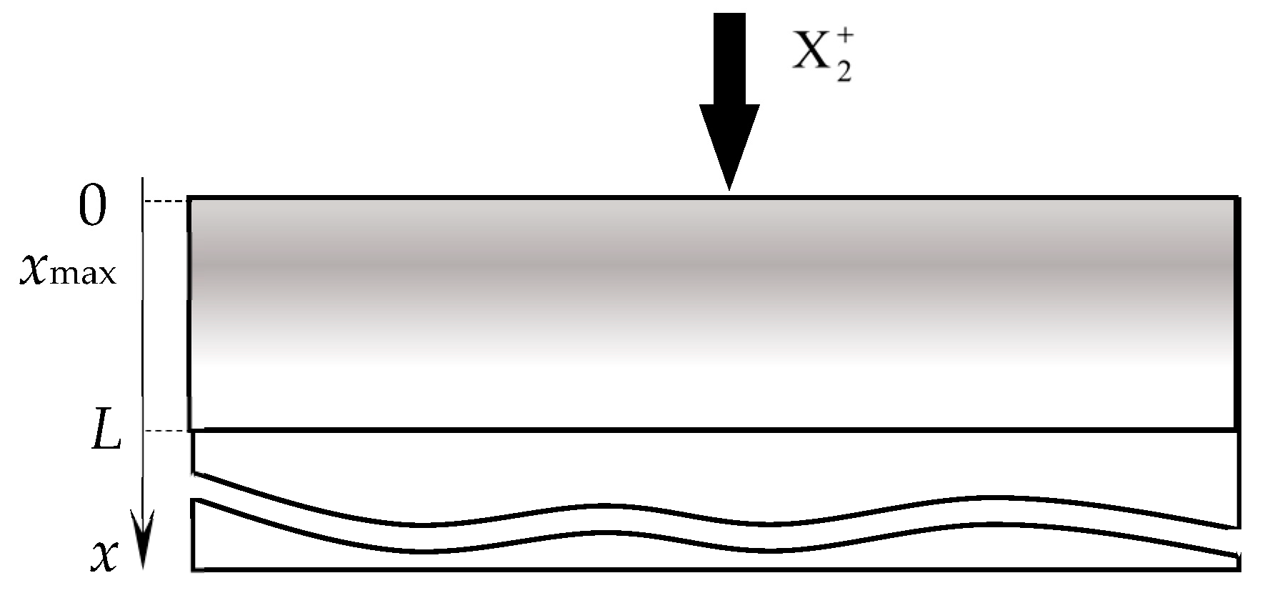
- The normalized distribution of projected ranges c(x) of ions along the normal to the target surface is a Gaussian:where Rp is the average ion range; ΔRp is the straggle;
- (4)
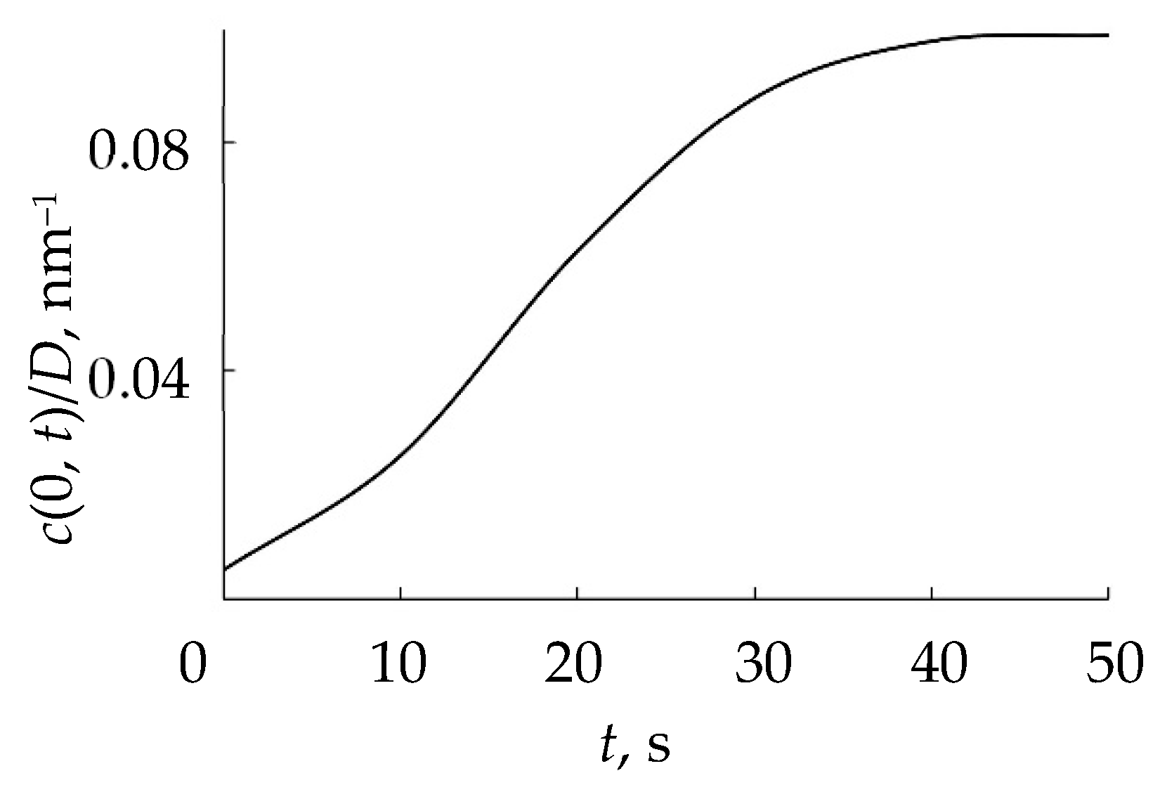
- The distribution of implanted atoms n(x, t) taking into account sputtering at a speed v0, is determined by the integral:where c(x − v0τ) is the normalized distribution taking into account sputtering;
- (5)
- The MmXn compound is formed:
- (5.1)
- On the surface due to chemisorption;
- (5.2)
- In the near-surface layers of the target due to the bulk chemical reactionbetween a part of implanted X atoms with metal atoms. The reaction rate is determined by the expressionmM + nX ↔ MmXnwhere k is the rate constant of the bulk reaction; nX (x, t) is the concentration of unreacted implanted X atoms, taking into account sputtering (see expression (42)); nM(x, t) is the concentration of free target atoms.
- (6)
- The formation of the MmXn layer on the surface is accompanied by the process:
- (6.1)
- Sputtering of MmXn molecules with argon ions;
- (6.2)
- Removal of X atoms from MmXn molecules due to the knock-on effect.
- (7)
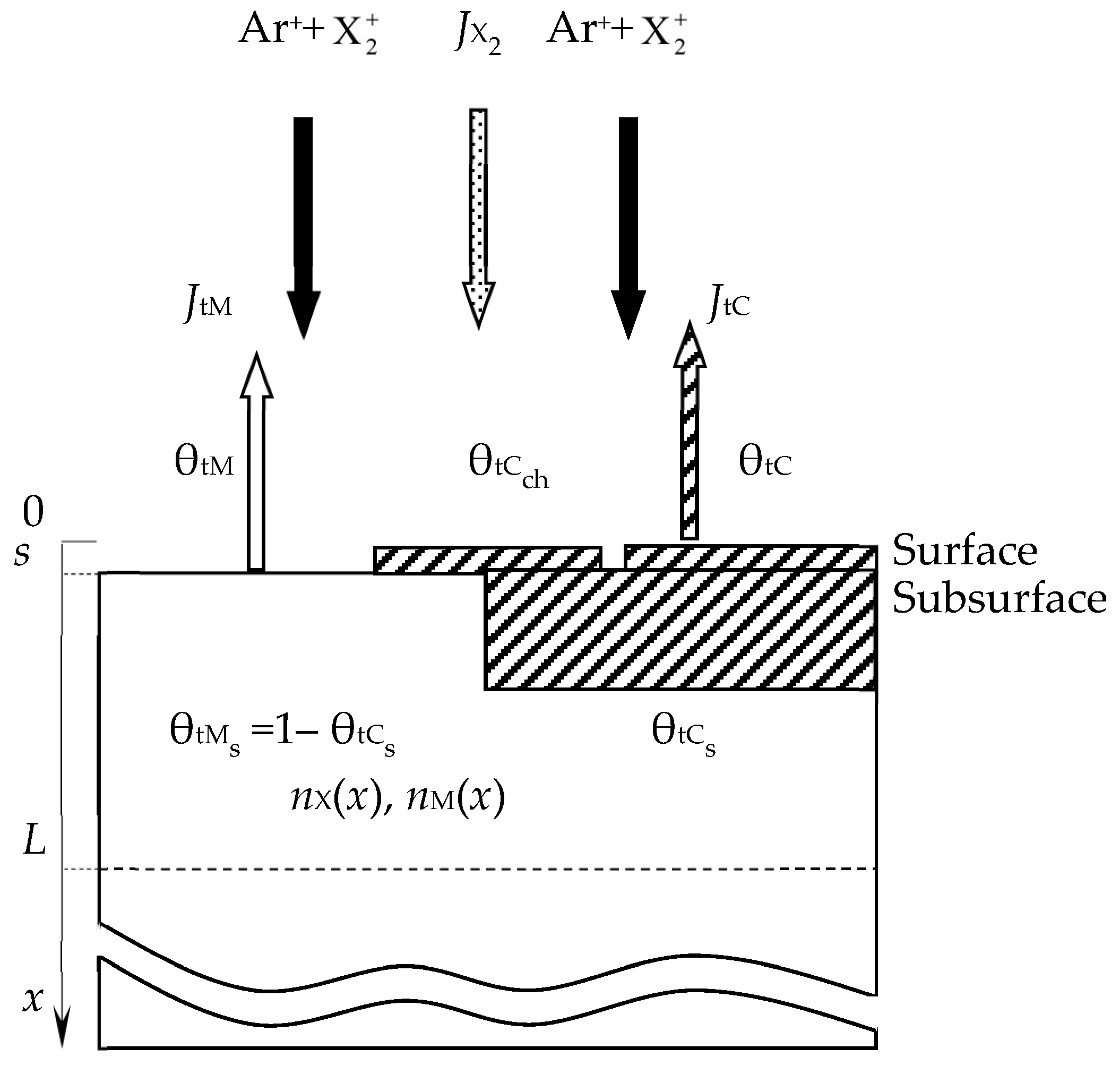
- In the area of the target surface, there are (Figure 14):
- (7.1)
- The layer from which the sputtering takes place directly (Surface). It has a thickness on the order of a monomolecular layer s. In the general case, this layer consists of sections: θtM, which is free of the MmXn compound film; θtC and θtCch, which are occupied by the MmXn compound formed due to direct implantation of X atoms and their chemisorption, respectively;
- (7.2)
- A subsurface region with a thickness L ≈ Rp ± 3ΔRp, into which reactive gas atoms are implanted, chemically interacting with the target material. In the model, this area is represented as a thin layer called Subsurface, as shown in Figure 14. It consists of the θtCs region occupied by the MmXn compound formed due to the bulk chemical reaction, and 1 − θtCs region occupied by free atoms of metal M.
- Formation of MmXn molecules on the fraction of the target surface θtM by chemisorption;
- Removal of MmXn molecules by sputtering;
- Removal of X atoms from MmXn molecules due to the knock-on effect. In fact, this process is also understood by the authors of the model as the removal of MmXn molecules.
4.2. Development of the RSD Model
4.3. Implantation
5. Nonisothermal Physicochemical Model (the Barybin Model)
5.1. Single Cold Target in Ar + X2
- The vacuum chamber contains a target, a substrate, and a wall. The areas of these elements are equal to At, As, and Aw (or Ai, i = t, s, w), respectively;
- During film synthesis, the surface temperatures Tt, Ts, and Tw (or Ti, i = t, s, w) are different, and the temperature of the gas environment T0 is equal to the wall temperature Tw;
- Every surface can undergo a chemical reaction:
- 4.
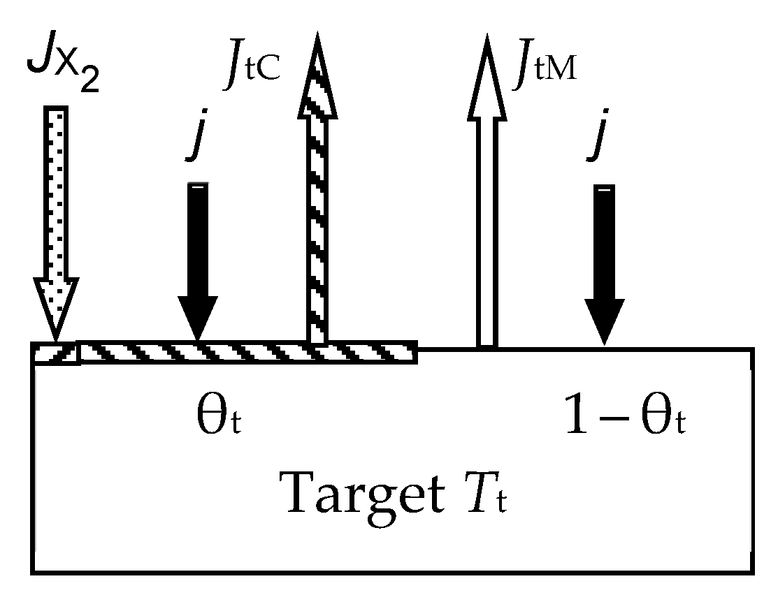
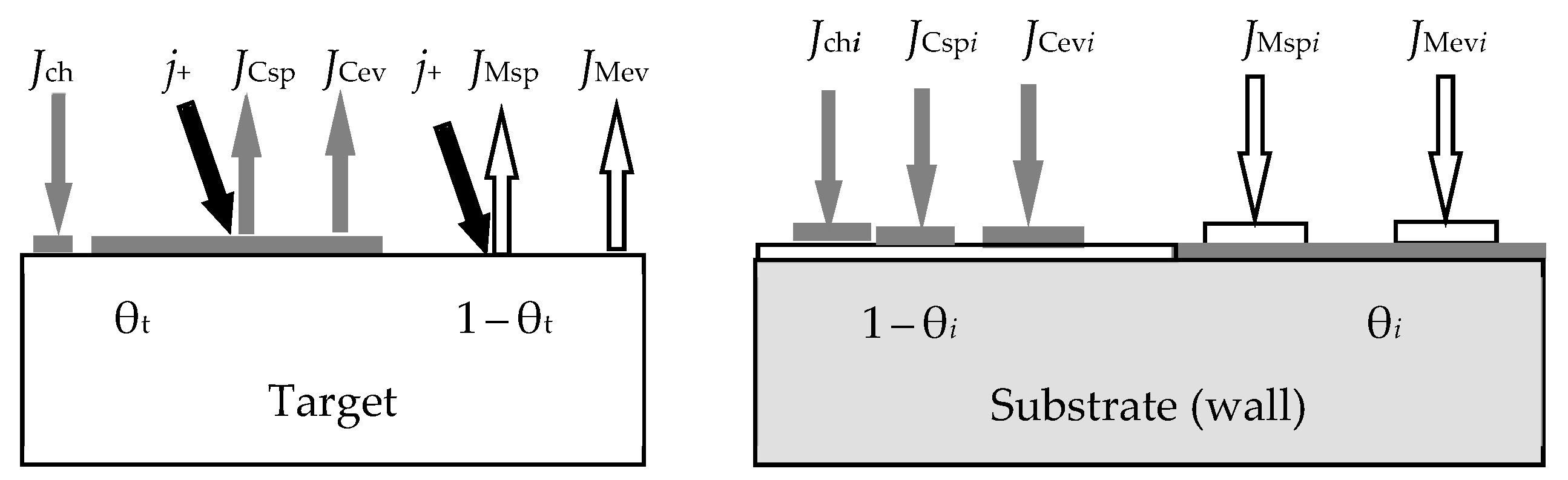
- At any time (see Figure 2):
- Relative fraction θt of the sputtered target surface is covered with MmXn. The rest (1 − θt) is pure metal M. This state can arise due to the competition of two processes, including the formation of the MmXn film according to surface reaction (55) and its sputtering with argon ions in the form of molecules. The flux sputtered from the target surface includes JtM (pure metal atoms M) and JtC (MmXn molecules);
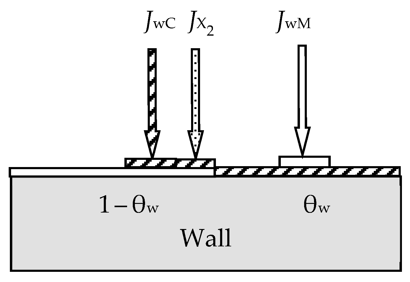
- Due to the surface reaction (55) and fluxes generated by the target, a solid solution M + MmXn is formed on the i-th surface (i = s, w). Let us represent it on each surface as two regions with relative areas θi and 1 − θi, containing the compound MmXn and the metal M, respectively.
- 5.
- Each surface consumes reactive gas to maintain surface reaction (55). Let Qi denote the flux incident on the i-th surface (i = t, s, w) and participating in the formation of the MmXn compound on it.
5.2. Single Cold Target in Ar + O2 + N2
- The vacuum chamber contains a target, a substrate, and a wall with surface areas Ai, i = t, s, w.
- The temperatures of the surfaces Ti, i = t, s, w are different, and the temperature of the gas environment T0 is equal to the wall temperature Tw.
- Metal oxynitride appears as a result of a surface chemical reaction on At, As, and Aw surfaces. We assume that this compound arises in the form of a solid solution consisting of MmOn oxide and MN nitride. In this case, the components of the solution are formed due to the occurrence of two independent reactions:were k1(T) and k2(T) are the reaction rate constants. Here and below, index 1 will correspond to oxide or oxygen, and index 2 to nitride or nitrogen. The accepted chemical formula for nitride in the form of MN corresponds to many compounds of this type (TiN, AlN, TaN, etc.).
- At any time:
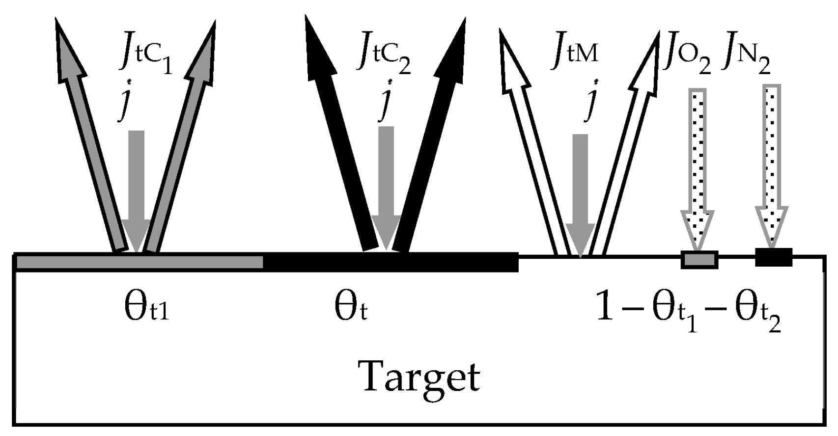
- Relative parts θt1 and θt2 of the sputtered target surface are covered by MmOn oxide and MN nitride, respectively (Figure 18). The rest (1 − θt1 − θt2) is pure metal M. This state can arise due to the competition of two processes, including the formation of the MmOn + MN solid solution film according to reactions (66) and (67) and its sputtering by argon ions in the form of molecules. The flux sputtered from the target surface includes JtM (pure metal atoms M), JtC1 (MmOn molecules), and JtC2 (MN molecules);
- Due to surface reactions (66) and (67) and fluxes generated by the target, a solid solution M + MmOn + MN is formed on the i-th surface (i = s, w). Let us represent it on each surface as three regions with relative areas θi1, θi2, and 1 − θi1 − θi2 containing oxide MmOn, nitride MN, and metal M, respectively.
- Each surface consumes reactive gas to maintain surface reactions (66) and (67). Let Qij denote the fluxes incident on the i-th surface (i = t, s, w) and participating in the formation of oxide MmOn (j = 1) and nitride MN (j = 2).
- Pumped gas flows Qp1 and Qp2, which for j =1, 2, are written by analogy with Equation (64):
- Flows to the target Qt1 and Qt2;
- Flows to the substrate, where the compound film is formed from the target material, Qs1 and Qs2;
- Flows to the chamber internal walls, where the target material is deposited, Qw1 and Qw2.
5.3. Single Hot Target in Ar + X2
- The vacuum chamber contains a target, a substrate, and a wall with surface areas Ai, i = t, s, w.
- The temperatures of the surfaces Ti, i = t, s, w are different, and the temperature of the gas environment is T0 = Tw. The target surface temperature Tt depends on the current density j.
- On a part of each surface free from the MmXn film, chemical reaction (55) can occur, which is preceded by the physical adsorption of molecules of reactive gas X2.
- At any moment in time (see Figure 20):
- The relative fraction θt of the sputtered target surface, as in any similar cases, is covered by MmXn. The rest (1 − θt) is a pure metal M. The flux sputtered from the target surface includes fluxes JtM (atoms of pure metal M) and JtC (molecules MmXn)The fluxes of sputtered metal atoms and compound molecules with densities and are proportional to the ion current density j+. The corresponding fluxes of evaporated particles with densities and depend indirectly on j:where AM, BM, AC, and BC are constants that determine the saturated vapor pressure of the metal M and the compound MmXn in pascals, respectively; mM and mC are the masses of the metal atom M and the MmXn molecule, respectively;
- On the i-th surface (i = s, w), due to the surface reaction (55) and fluxes generated by the target, a solid solution M + MmXn is formed. Let us represent it on each surface as two regions with relative areas θi and 1 − θi containing the compound MmXn and the metal M, respectively (see Figure 20).
- A flow of reactive gas Qi falls on each surface, supporting the formation of the compound MmXn according to reaction (55).
- The discharge current density iswhere γ is the potential ion-induced secondary electron emission yield; j+ is the ion current density; j− is the current density of thermal electron emission (described by the Richardson–Dushman equation):where A ≈ 120 A∙cm−2∙K−2; φt is the work function of electrons for the target material; k is the Boltzmann constant.
- The influence of the temperature on the parameters of the sputtering process (sputtering yield and ion-induced electron emission yield, etc.) is insignificant.
- Reactive gas flows on each of the three internal surfaces of the vacuum chamber (63);
- Balance of gas flows (64);
- Pumping out the vacuum chamber (65).
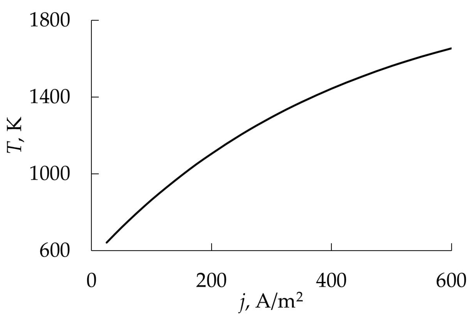
- Hysteresis persists over a wide temperature range. In accordance with expression (95), current densities of 50 and 500 A/m2 corresponded to temperatures of 720 and 1560 K;
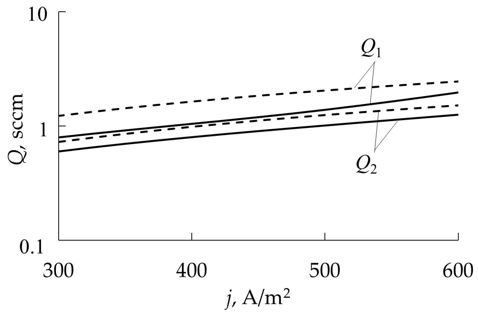
- Changes in the operating mode of the target occur at lower values of Q1 and Q2 compared to a cold target (Figure 22);
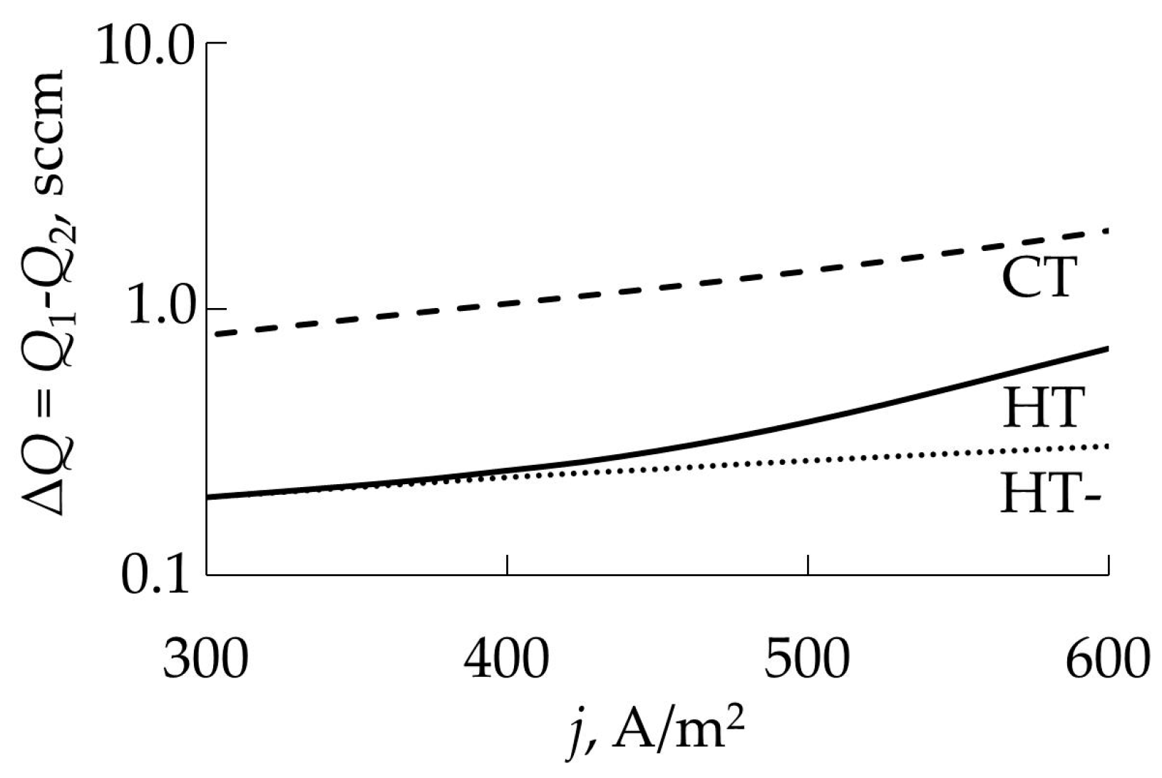
- The width of the hysteresis loop also has smaller values (Figure 23).
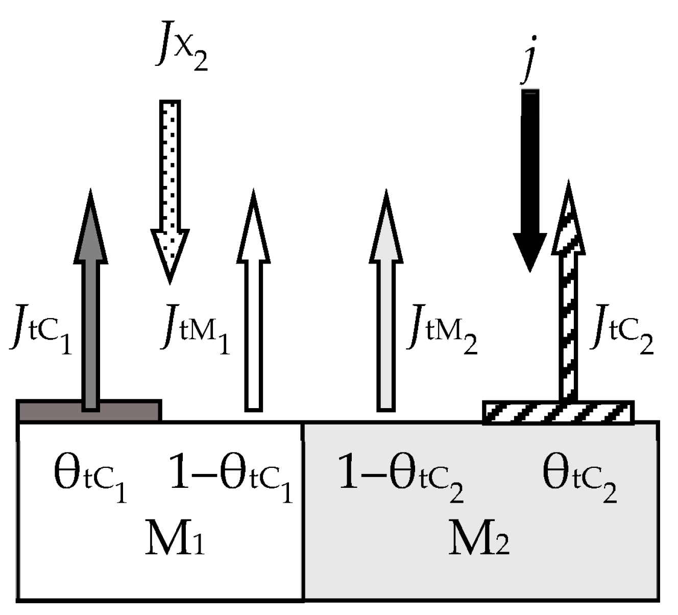
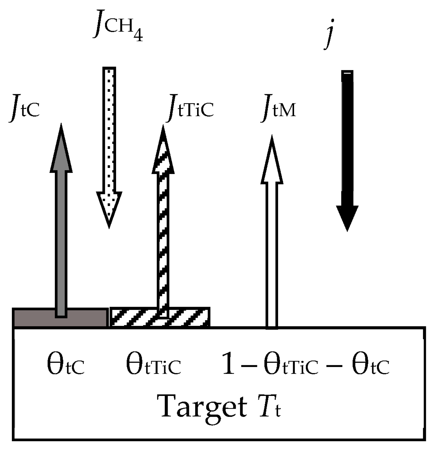
5.4. Sandwich Target in Ar + X2
- The vacuum chamber includes four elements: the internal and external plates located in the sputtering unit on the same axis [194], the substrate, and the wall. The areas of these elements are denoted by Ai, i = t1, t2, s, w. Cut-outs with a total area of Aco are made in the external plate. The values At1 and At2 specify the areas of only the sputtered fractions of the plates. On the external plate, this fraction is ring-shaped with geometric dimensions determined by the magnetic field. If the area of the ring is A, then the actual sputtered area of the external plate is At2 = A − Aco or in relative units At2/A = (A − Aco)/A = 1 − Aco/A = 1 − δco. Furthermore, the area of the sputtered region of the internal plate At1 in this design is determined by the equality At1 = Aco, and its relative value is At1/A = Aco/A = δco.
- The temperatures of the surfaces Ti, i = t1, t2, s, w are different. The temperature of the gas environment T0 is equal to the wall temperature Tw. The internal plate works in cold mode, and the external one in hot mode.
- Two reactions can take place on each surface:where mj and nj (j = 1, 2) are the stoichiometric coefficients; kj (Ti) (j = 1, 2) are the Arrhenius equation for the reaction rate constants, which have the dimension of the flux density by analogy with (56);
- The discharge current densitywhere jt1 is the component related to the internal plate, and it is determined by the fraction of the cut-out area δco = Aco/A in the sputtered region of the external plate:Current share jt2 in (98) is equal to
- Two processes occur on the surface of the external plate, which should be taken into account in the model:
- Thermal electron emission (the Richardson–Dushman Equation (86));
- Evaporation (the Hertz–Knudsen equation by analogy with (90)).
- At any moment in time:
- Fraction θt1 of the sputtered region of the internal plate is covered by the M1m1Xn1 film. The rest (1 − θt1) is pure metal M1;
- In the sputtered region of the external plate, the similar regions for M2m2Xn2 and M2 will be denoted by θt2 and (1 − θt2), respectively;
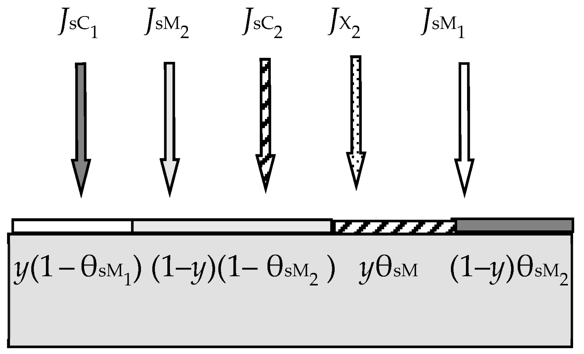
- On the i-th surface (i = s, w) due to reactions (96) and (97) and fluxes generated by the plates, a solid solution M1 + M2 + M1m1Xn1 + M2m2Xn2 is formed. On each surface, the solid solution is represented in the form of four regions with relative areas θi1, θi1, θin1, and θin2 containing the corresponding components of the solution. In this case, it is obvious that θi1 + θi2 +θin1 + θin2 = 1.
- Each i-th surface (i = t1, t2, s, w) consumes the reactive gas to support reactions (96) and (97). Let Qij denote the fluxes incident on the i-th surface (i = t1, t2, s, w) and participating in the formation of the j-th compound (j = 1, 2).
- The first of them contains equations describing the kinetics of processes occurring on all surfaces specified in the model;
- The second group consists of equations describing reactive gas flows to all surfaces and equations for pumping and balance of gas flows.
6. Summary
Funding
Data Availability Statement
Acknowledgments
Conflicts of Interest
References
- Greene, J.E. Review Article: Tracing the recorded history of thin-film sputter deposition: From the 1800s to 2017. J. Vac. Sci. Technol. A Vac. Surf. Films 2017, 35, 05C204. [Google Scholar] [CrossRef]
- Holland, L.; Siddall, G. The properties of some reactively sputtered metal oxide films. Vacuum 1953, 3, 375–391. [Google Scholar] [CrossRef]
- Veszi, G.A. The modern single-layer selenium photo-electric cell. J. Br. Inst. Radio Eng. 1953, 13, 183–189. [Google Scholar] [CrossRef]
- Reith, T.M.; Ficalora, P.J. The reactive sputtering of tantalum oxide: Compositional uniformity, phases, and transport mechanisms. J. Vac. Sci. Technol. A Vac. Surf. Films 1983, 1, 1362–1369. [Google Scholar] [CrossRef]
- Kwok, C.; Aita, C.R. The transition from αZr to αZrO2 growth in sputter-deposited films as a function of gas O2 content, rare-gas type, and cathode voltage. J. Vac. Sci. Technol. A Vac. Surf. Films 1989, 7, 1235–1239. [Google Scholar] [CrossRef]
- Aita, C.R.; Purdes, A.J.; Lad, K.L.; Funkenbusch, P.D. The effect of O2 on reactively sputtered zinc oxide. J. Appl. Phys. 1980, 51, 5533. [Google Scholar] [CrossRef]
- Ohsaki, H.; Tachibana, Y.; Shimizu, J.; Oyama, T. High-rate deposition of SiO2 by modulated DC reactive sputtering in the transition mode without a feedback system. Thin Solid Films 1996, 281–282, 213–217. [Google Scholar] [CrossRef]
- Geraghty, K.G. Kinetics of the Reactive Sputter Deposition of Titanium Oxides. J. Electrochem. Soc. 1976, 123, 1201. [Google Scholar] [CrossRef]
- Glew, M.R.L.; Vollmer, A.; Schroeder, S.L.M.; Barber, Z.H. The characterization of TiN thin films using optical reflectivity measurements. J. Phys. D Appl. Phys. 2002, 35, 2643–2647. [Google Scholar] [CrossRef]
- Howson, R.P.; Spencer, A.G.; Oka, K.; Lewin, R.W. The formation and control of direct current magnetron discharges for the high-rate reactive processing of thin films. J. Vac. Sci. Technol. A 1989, 7, 1230–1234. [Google Scholar] [CrossRef]
- Ngaruiya, J.M.; Venkataraj, S.; Drese, R.; Kappertz, O.; Leervad Pedersen, T.P.; Wuttig, M. Preparation and characterization of tantalum oxide films produced by reactive DC magnetron sputtering. Phys. Stat. Sol. (A) 2003, 198, 99–110. [Google Scholar] [CrossRef]
- Venkataraj, S.; Drese, R.; Kappertz, O.; Jayavel, R.; Wuttig, M. Characterization of Niobium Oxide Films Prepared by Reactive DC Magnetron Sputtering. Phys. Stat. Sol. (A) 2001, 188, 1047–1058. [Google Scholar] [CrossRef]
- Kusano, E.; Kusano, E.; Baba, S.; Kinbara, A. Approach to estimate gettering effects in Ti–O2 reactive sputtering process. J. Vac. Sci. Technol. A 1992, 10, 1696–1700. [Google Scholar] [CrossRef]
- Jones, F.; Logan, J. High-rate reactive sputter deposition of aluminum oxide. J. Vac. Sci. Technol. A 1989, 7, 1240–1247. [Google Scholar] [CrossRef]
- Heller, J. Reactive sputtering of metalls in oxidising atmospheres. Thin Solid Films 1973, 17, 163–176. [Google Scholar] [CrossRef]
- Schiller, S.; Heisig, U.; Steinfelder, K.; Strümpfel, J. Reactive DC sputtering with the magnetron-plasmatron for tantalum pentoxide and titanium dioxide films. Thin Solid Films 1979, 63, 369–375. [Google Scholar] [CrossRef]
- Kim, J.-Y.; Nielsen, M.C.; Rymaszewski, E.J.; Lu, T.-M. Electrical characteristics of thin Ta2O5 films deposited by reactive pulsed direct-current magnetron sputtering. J. Appl. Phys. 2000, 87, 1448–1452. [Google Scholar] [CrossRef]
- Goranchev, B.; Orlinov, V.; Popova, V.D.C. Cathode sputtering: Influence of the oxigen content in the gas flow on the discharge current. Thin Solid Films 1976, 33, 173–183. [Google Scholar] [CrossRef]
- Lemperière, G.; Poitevin, J.M. Influence of the nitrogen partial pressure on the properties of dc-sputtered titanium and tantalum nitride films. Thin Solid Films 1984, 111, 339–349. [Google Scholar] [CrossRef]
- Hmiel, A.F. Partial pressure control of reactivly sputtered titanium nitride. J. Vac. Sci. Technol. A 1985, 3, 592–595. [Google Scholar] [CrossRef]
- Shinoki, F.; Itoh, A. Mechanism of rf reactive sputtering. J. Appl. Phys. 1975, 6, 3381–3384. [Google Scholar] [CrossRef]
- Hohnke, D.K.; Schmatz, D.J.; Hurley, M.D. Reactive sputter deposition: A quantitative analysis. Thin Solid Films 1984, 118, 301–310. [Google Scholar] [CrossRef]
- Zhang, W.; Li, Y.; Zhu, S.; Wang, F. Fe-doped photocatalytic TiO2 film prepared by pulsed dc reactive magnetron sputtering. J. Vac. Sci. Technol. A 2003, 21, 1877–1882. [Google Scholar] [CrossRef]
- Schiller, S. Reactive high rate d.c. sputtering: Deposition rate, stoichiometry and features of TiOx and TiNx films with respect to the target mode. Thin Solid Films 1984, 111, 259–268. [Google Scholar] [CrossRef]
- Kusano, E. An investigation of hysteresis effects as a function of pumping speed, sputtering current, and O2/Ar ratio, in Ti-O2 reactive sputtering processes. J. Appl. Phys. 1991, 70, 7089–7096. [Google Scholar] [CrossRef]
- Steenbeck, K.; Steinbeiß, E.; Ufert, K.-D. The problem of reactive sputtering and cosputtering of elemental targets. Thin Solid Films 1982, 92, 371–380. [Google Scholar] [CrossRef]
- Wolter, M.; Do, H.T.; Steffen, H.; Hippler, R. Aluminium atom density and temperature in a dc magnetron discharge determined by means of blue diode laser absorption spectroscopy. J. Phys. D Appl. Phys. 2005, 38, 2390–2395. [Google Scholar] [CrossRef]
- Maniv, S.; Westwood, W.D. Discharge characteristics for magnetron sputtering of Al in Ar and Ar/O2 mixtures. Vac. Sci. Technol. 1979, 17, 743–751. [Google Scholar] [CrossRef]
- Maniv, S.; Westwood, W.D. Surface oxidation kinetics of sputtering targets. Surf. Sci. 1980, 100, 108–118. [Google Scholar] [CrossRef]
- Maniv, S.; Miner, C.; Westwood, W.D. High rate deposition of transparent conducting films by modified reactive planar magnetron sputtering of Cd2Sn alloy. J. Vac. Sci. Technol. 1981, 18, 195–198. [Google Scholar] [CrossRef]
- Maniv, S.; Westwood, W.D.; Colombini, E. Pressure and angle of incidence effects in planar magnetron sputtered ZnO layers. J. Vac. Sci. Technol. 1982, 20, 162–170. [Google Scholar] [CrossRef]
- Jain, P.; Bhagwat, V.; Rymaszewski, E.J.; Lu, T.M.; Berg, S.; Cale, T.S. Model relating process variables to film electrical properties for reactively sputtered tantalum oxide thin films. J. Appl. Phys. 2003, 93, 3596–3604. [Google Scholar] [CrossRef]
- Westlinder, J.; Zhang, Y.; Engelmark, F.; Possnert, G.; Blom, H.-O.; Olsson, J.; Berg, S. Simulation and dielectric characterization of reactive dc magnetron cosputtered (Ta2O5)1–x(TiO)x thin films. J. Vac. Sci. Technol. B 2002, 20, 855–861. [Google Scholar] [CrossRef]
- McMahon, R.; Affinito, J.; Parsons, R.R. Voltage controlled, reactiv planar magnetron sputtering of AlN thin films. J. Vac. Sci. Technol. 1982, 20, 376–378. [Google Scholar] [CrossRef]
- Berg, S.; Larsson, T.; Blom, H. The use of nitrogen flow as a deposition rate control in reactive sputtering. J. Vac. Sci. Technol. A 1986, 4, 594–597. [Google Scholar] [CrossRef]
- Berg, S.; Blom, H.-O.; Moradi, M.; Nender, C.; Larsson, T. Process modeling of reactive sputtering. J. Vac. Sci. Technol. A 1989, 7, 1225–1229. [Google Scholar] [CrossRef]
- Affinito, J.; Parsons, R.R. Mechanisms of voltage controlled, reactive, planar magnetron sputtering of Al in Ar/N2 and Ar/O2 atmospheres. J. Vac. Sci. Technol. A 1984, 2, 1275–1284. [Google Scholar] [CrossRef]
- Abe, T.; Yamashina, T. The deposition rate of metallic thin films in the reactive sputtering process. Thin Solid Films 1975, 30, 19–27. [Google Scholar] [CrossRef]
- Eltoukhy, A.H.; Natarajan, B.R.; Greene, J.E.; Barr, T.L. Mechanism of reactive sputtering of Indium III: A general phenomenological model for reactive sputtering. Thin Solid Films 1980, 69, 229–235. [Google Scholar] [CrossRef]
- Yoshitake, M.; Takiguchi, K.; Suzuki, Y.; Ogawa, S. Effect of pressure in reactive ion beam sputter deposition of zirconium oxides. J. Vac. Sci. Technol. A 1988, 6, 2326–2332. [Google Scholar] [CrossRef]
- Avaritsiotis, J.N.; Tsiogas, C.D. A reactive sputtering process model for symmetrical planar diode systems. Thin Solid Films 1992, 209, 17–25. [Google Scholar] [CrossRef]
- Kusano, E.; Goulart, D.M. Time-dependent simulation modelling of reactive sputtering. Thin Solid Films 1990, 193–194, 84–91. [Google Scholar] [CrossRef]
- Kusano, E.; Kinbara, A. Investigation of the effect of pumping speed and Ar/O2 ratio on the transient time mode transition in Ti–O2 reactive sputtering. Thin Solid Films 1996, 281–282, 423–426. [Google Scholar] [CrossRef]
- Zhu, S.; Wang, F.; Wu, W. Simulations of reactive sputtering with constant voltage power supply. J. Appl. Phys. 1998, 84, 6399–6408. [Google Scholar] [CrossRef]
- Zhu, S.; Wang, F.; Wu, W. Abnormal steady states in reactive sputtering. J. Vac. Sci. Technol. 1999, 7, 70–76. [Google Scholar] [CrossRef]
- Berg, S.; Blom, H.; Larsson, T.; Nender, C. Modeling of reactive sputtering of compound materials. J. Vac. Sci. Technol. 1987, 5, 202–207. [Google Scholar] [CrossRef]
- Berg, S.; Larsson, T.; Nender, C.; Blom, H. Predicting thin film stoichiometry in reactive sputtering. J. Appl. Phys. 1988, 63, 887–891. [Google Scholar] [CrossRef]
- Larsson, T.; Blom, H.; Nender, C.; Berg, S. A physical model for eliminating instabilities in reactive sputtering. J. Vac. Sci. Technol. A 1988, 6, 1832–1836. [Google Scholar] [CrossRef]
- Moradi, M.; Nender, C.; Berg, S.; Blom, H.; Belkind, A.; Orban, Z. Modeling of multicomponent reactive sputtering. J. Vac. Sci. Technol. A 1991, 9, 619–624. [Google Scholar] [CrossRef]
- Larsson, T.; Berg, S.; Blom, H.-O. Modelling of reactive sputtering of titanium boride. Thin Solid Films 1989, 172, 241–249. [Google Scholar] [CrossRef]
- Carlsson, P.; Nender, C.; Barankova, H.; Berg, S. Reactive sputtering using two reactive gases. J. Vac. Sci. Technol. A 1993, 11, 1534–1539. [Google Scholar] [CrossRef]
- Baránková, H.; Berg, S.; Carlsson, P.; Nender, C. Hysteresis effects in the sputtering process using two reactive gases. Thin Solid Films 1995, 260, 181–186. [Google Scholar] [CrossRef]
- Sekiguchi, H.; Murakami, T.; Kanzawa, A.; Imai, T.; Honda, T. Computational modeling of reactive gas modulation in radio frequency reactive sputtering. Vac. Sci.Technol. A 1996, 14, 2231–2234. [Google Scholar] [CrossRef]
- Nyberg, T.; Högberg, H.; Greczynski, G.; Berg, S. A simple model for non-saturated reactive sputtering processes. Thin Solid Films 2019, 688, 137413. [Google Scholar] [CrossRef]
- Berg, S.; Moradi, M.; Nender, C.; Blom, H.-O. The use of process modelling for optimum design of reactive sputtering processes. Surf. Coat. Technol. 1989, 39–40, 465–474. [Google Scholar] [CrossRef]
- Severin, D.; Kappertz, O.; Kubart, T.; Nyberg, T.; Berg, S.; Pflug, A.; Siemers, M.; Wuttig, M. Process stabilization and increase of the deposition rate in reactive sputtering of metal oxides and oxynitrides. Appl. Phys. Lett. 2006, 88, 161504. [Google Scholar] [CrossRef]
- Engelmark, F.; Westlinder, J.; Nyberg, T.; Berg, S. Experimental and computer simulation studies of the “baffled target” reactive sputtering process. J. Vac. Sci. Technol. A Vac. Surf. Films 2003, 21, 1981–1987. [Google Scholar] [CrossRef]
- Larsson, T. A model for reactive sputtering with magnetrons. Vacuum 1989, 39, 949–954. [Google Scholar] [CrossRef]
- Nyberg, T.; Berg, S.; Helmersson, U.; Hartig, K. Eliminating the hysteresis effect for reactive sputtering processes. Appl. Phys. Lett. 2005, 86, 164106. [Google Scholar] [CrossRef]
- Kubart, T.; Trinh, D.H.; Liljeholm, L.; Hultman, L.; Högberg, H.; Nyberg, T.; Berg, S. Experiments and modeling of dual reactive magnetron sputtering using two reactive gases. J. Vac. Sci. Technol. A Vac. Surf. Films 2008, 26, 565–570. [Google Scholar] [CrossRef]
- Kubart, T.; Depla, D.; Martin, D.M.; Nyberg, T.; Berg, S. High rate reactive magnetron sputter deposition of titanium oxide. Appl. Phys. Lett. 2008, 92, 221501. [Google Scholar] [CrossRef]
- Severin, D.; Kappertz, O.; Nyberg, T.; Berg, S.; Pflug, A.; Wuttig, M. Increase of the deposition rate in reactive sputtering of metal oxides using a ceramic nitride target. J. Appl. Phys. 2009, 105, 093302. [Google Scholar] [CrossRef]
- Betz, G. Alloy sputtering. Surf. Sci. 1980, 92, 283–309. [Google Scholar] [CrossRef]
- Macák, K.; Nyberg, T.; Macák, P.; Kharrazi Olsson, M.; Helmersson, U.; Berg, S. Modeling of the deposition of stoichiometric Al2O3 using nonarcing direct current magnetron sputtering. J. Vac. Sci. Technol. A Vac. Surf. Films 1998, 16, 1286–1292. [Google Scholar] [CrossRef]
- Strijckmans, K.; Schelfhout, R.; Depla, D. Tutorial: Hysteresis during the reactive magnetron sputtering process. J. Appl. Phys. 2018, 124, 241101. [Google Scholar] [CrossRef]
- Madarász, R.R.; Kelemen, A.; Hungarian, S.; Kádár, P. Modeling reactive magnetron sputtering: A survey of different modeling approaches. Acta Univ. Sapientiae Inform. 2020, 12, 112–136. [Google Scholar] [CrossRef]
- Hegedüs, N.; Balázsi, C.; Kolonits, T.; Olasz, D.; Sáfrán, G.; Serényi, M.; Balázsi, K. Investigation of the RF Sputtering Process and the Properties of Deposited Silicon Oxynitride Layers under Varying Reactive Gas Conditions. Materials 2022, 15, 6313. [Google Scholar] [CrossRef] [PubMed]
- Thornton, J.A. Substrate heating in cylindrical magnetron sputtering sources. Thin Solid Films 1978, 54, 23–31. [Google Scholar] [CrossRef]
- Jain, P.; Juneja, J.S.; Bhagwat, V.; Rymaszewski, E.J.; Lu, T.-M.; Cale, T.S. Effects of substrate temperature on properties of pulsed dc reactively sputtered tantalum oxide films. J. Vac. Sci. Technol. A Vac. Surf. Films 2005, 23, 512–519. [Google Scholar] [CrossRef]
- Cheng, H.-E.; Mao, C.-T. The effect of substrate temperature on the physical properties of tantalum oxide thin films grown by reactive radio-frequency sputtering. Mater. Res. Bull. 2003, 38, 1841–1849. [Google Scholar] [CrossRef]
- Rosén, D.; Katardjiev, I.; Berg, S.; Möller, W. TRIDYN simulation of target poisoning in reactive sputtering. Nuclear Instr. Meth. Phys. Res. Sect. B Beam Inter. Mater. Atoms. 2005, 228, 193–197. [Google Scholar] [CrossRef]
- Berg, S.; Nyberg, T. Fundamental understanding and modeling of reactive sputtering processes. Thin Solid Films 2005, 476, 215–230. [Google Scholar] [CrossRef]
- Depla, D.; Haemers, J.; Gryse, R.D. Target surface condition during reactive glow discharge sputtering of copper. Plasma Sources Sci. Technol. 2002, 11, 91–96. [Google Scholar] [CrossRef]
- Kubart, T.; Kappertz, O.; Nyberg, T.; Berg, S. Dynamic behaviour of the reactive sputtering process. Thin Solid Films 2006, 515, 421–424. [Google Scholar] [CrossRef]
- Berg, S.; Särhammar, E.; Nyberg, T. Upgrading the «Berg-model» for reactive sputtering processes. Thin Solid Films 2014, 565, 186–192. [Google Scholar] [CrossRef]
- Särhammar, E.; Nyberg, T.; Berg, S. Applying “the upgraded Berg model” to predict hysteresis free reactive sputtering. Surf. Coat. Technol. 2015, 279, 39–43. [Google Scholar] [CrossRef]
- Kubart, T.; Gudmundsson, J.T.; Lundin, D. Reactive high power impulse magnetron sputtering. In High Power Impulse Magnetron Sputtering; Elsevier: Amsterdam, The Netherlands, 2020; pp. 223–263. [Google Scholar] [CrossRef]
- Sproul, W. High-rate reactive DC magnetron sputtering of oxide and nitride superlattice coatings. Vacuum 1998, 51, 641–646. [Google Scholar] [CrossRef]
- Sproul, W.D.; Christie, D.J.; Carter, D.C. Control of reactive sputtering processes. Thin Solid Films 2005, 491, 1–17. [Google Scholar] [CrossRef]
- Möller, W.; Güttler, D. Modeling of plasma-target interaction during reactive magnetron sputtering of TiN. J. Appl. Phys. 2007, 102, 094501. [Google Scholar] [CrossRef]
- Wallin, E.; Helmersson, U. Hysteresis-free reactive high power impulse magnetron sputtering. Thin Solid Films 2008, 516, 6398–6401. [Google Scholar] [CrossRef]
- Sagás, J.C.; Duarte, D.A.; Irala, D.R.; Fontana, L.C.; Rosa, T.R. Modeling reactive sputter deposition of titanium nitride in a triode magnetron sputtering system. Surf. Coat. Technol. 2011, 206, 1765–1770. [Google Scholar] [CrossRef]
- Tonneau, R.; Moskovkin, P.; Pflug, A.; Lucas, S. TiOx deposited by magnetron sputtering: A joint modelling and experimental study. J. Phys. D Appl. Phys. 2018, 51, 195202. [Google Scholar] [CrossRef]
- Fekete, M.; Bernátová, K.; Klein, P.; Hnilica, J.; Vašina, P. Influence of sputtered species ionisation on the hysteresis behaviour of reactive HiPIMS with oxygen admixture. Plasma Sources Sci. Technol. 2020, 29, 025027. [Google Scholar] [CrossRef]
- Petroski, K.A.; Sagás, J.C. Alternative anode geometry for magnetron sputtering. Vacuum 2020, 182, 109703. [Google Scholar] [CrossRef]
- Hashimoto, S.; Tanaka, A.; Murata, A.; Sakurada, T. Formulation for XPS spectral change of oxides by ion bombardment as a function of sputtering time. Surf. Sci. 2004, 556, 22–32. [Google Scholar] [CrossRef]
- Vašina, P.; Hytková, T.; Eliáš, M. Modelling of the reactive sputtering process with non-uniform discharge current density and different temperature conditions. Plasma Sources Sci. Technol. 2009, 18, 025011. [Google Scholar] [CrossRef]
- Kozák, T.; Vlček, J. A parametric model for reactive high-power impulse magnetron sputtering of films. J. Phys. D Appl. Phys. 2015, 49, 055202. [Google Scholar] [CrossRef]
- Jonsson, L.B.; Nyberg, T.; Katardjiev, I.; Berg, S. Frequency response in pulsed DC reactive sputtering processes. Thin Solid Film. 2000, 365, 43–48. [Google Scholar] [CrossRef]
- Karnopp, J.; Sagás, J.C. Including substrate temperature in Berg model for reactive sputtering. Thin Solid Films 2019, 696, 137761. [Google Scholar] [CrossRef]
- Faddeeva, S.; Oseguera, J. Thermodynamic model of reactive sputtering process. Surf. Eng. 2012, 28, 639–645. [Google Scholar] [CrossRef]
- Faddeeva, S.; Oseguera, J. Method to design stoichiometric deposition reactive sputtering without hysteresis. Surf. Eng. 2013, 29, 547–554. [Google Scholar] [CrossRef]
- Shashin, D.E.; Sushentsov, N.I.; Stepanov, S.A. Mathematical model development for thin zinc oxide film formation with assigned dielectric constant values. J. Phys. Conf. Ser. 2019, 1313, 012049. [Google Scholar] [CrossRef]
- Woelfel, C.; Awakowicz, P.; Lunze, J. Model reduction and identification of nonlinear reactive sputter processes. IFAC-PapersOnLine 2017, 50, 13728–13734. [Google Scholar] [CrossRef]
- Woelfel, C.; Bockhorn, D.; Awakowicz, P.; Lunze, J. Model approximation and stabilization of reactive sputter processes. J. Proc. Contr. 2018, 83, 121–128. [Google Scholar] [CrossRef]
- Musil, J.; Baroch, P.; Vlček, J.; Nam, K.H.; Han, J.G. Reactive magnetron sputtering of thin films: Present status and trends. Thin Solid Films 2005, 475, 208–218. [Google Scholar] [CrossRef]
- Depla, D.; Colpaert, A.; Eufinger, K.; Segers, A.; Haemers, J.; De Gryse, R. Target voltage behaviour during DC sputtering of silicon in an argon/nitrogen mixture. Vacuum 2002, 66, 9–17. [Google Scholar] [CrossRef]
- Mahieu, S.; De Winter, G.; Depla, D.; De Gryse, R.; Denul, J. A model for the development of biaxial alignment in yttria stabilized zirconia layers, deposited by unbalanced magnetron sputtering. Surf. Coat. Technol. 2004, 187, 122–130. [Google Scholar] [CrossRef]
- Mahieu, S.; Ghekiere, P.; De Winter, G.; Heirwegh, S.; Depla, D.; De Gryse, R.; Lebedev, O.I.; Van Tendeloo, G. Mechanism of preferential orientation in sputter deposited titanium nitride and yttria-stabilized zirconia layers. J. Cryst. Growth 2005, 279, 100–109. [Google Scholar] [CrossRef]
- Mahieu, S.; Ghekiere, P.; De Winter, G.; Depla, D.; De Gryse, R.; Lebedev, O.I.; Van Tendeloo, G. Influence of the Ar/O2 ratio on the growth and biaxial alignment of yttria stabilized zirconia layers during reactive unbalanced magnetron sputtering. Thin Solid Films 2005, 484, 18–25. [Google Scholar] [CrossRef]
- Mahieu, S.; Ghekiere, P.; De Winter, G.; De Gryse, R.; Depla, D.; Van Tendeloo, G.; Lebedev, O.I. Biaxially aligned titanium nitride thin films deposited by reactive unbalanced magnetron sputtering. Surf. Coat. Technol. 2006, 200, 2764–2768. [Google Scholar] [CrossRef]
- Mahieu, S.; Buyle, G.; Ghekiere, P.; Heirwegh, S.; De Gryse, R.; Depla, D. Mechanism of biaxial alignment in thin films, deposited by magnetron sputtering. Thin Solid Films 2006, 515, 416–420. [Google Scholar] [CrossRef]
- Mahieu, S.; Ghekiere, P.; Depla, D.; De Gryse, R. Biaxial alignment in sputter deposited thin films. Thin Solid Films 2006, 515, 1229–1249. [Google Scholar] [CrossRef]
- Depla, D.; Heirwegh, S.; Mahieu, S.; Haemers, J.; De Gryse, R. Understanding the discharge voltage behavior during reactive sputtering of oxides. J. Appl. Phys. 2007, 101, 013301. [Google Scholar] [CrossRef]
- Georgieva, V.; Saraiva, M.; Jehanathan, N.; Lebelev, O.I.; Depla, D.; Bogaerts, A. Sputter-deposited Mg-Al-O thin films: Linking molecular dynamics simulations to experiments. J. Phys. D Appl. Phys. 2009, 42, 065107. [Google Scholar] [CrossRef]
- Saraiva, M.; Persoons, R.; Depla, D. Composition-crystallinity-property relations in Mg-M-O films. J. Appl. Phys. 2012, 111, 103532. [Google Scholar] [CrossRef]
- Depla, D.; Haemers, J.; De Gryse, R. Influencing the hysteresis during reactive magnetron sputtering by gas separation. Surf. Coat. Technol. 2013, 235, 62–67. [Google Scholar] [CrossRef]
- Lamas, J.S.; Leroy, W.P.; Lu, Y.-G.; Verbeeck, J.; Van Tendeloo, G.; Depla, D. Using the macroscopic scale to predict the nano-scale behavior of YSZ thin films. Surf. Coat. Technol. 2014, 238, 45–50. [Google Scholar] [CrossRef]
- Depla, D.; Besnard, A.; Lamas, J. The influence of the pressure on the microstructure of yttria-stabilized zirconia thin films deposited by dual magnetron sputtering. Vacuum 2016, 125, 118–122. [Google Scholar] [CrossRef]
- Moens, F.; Konstantinidis, S.; Depla, D. The Target Material Influence on the Current Pulse during High Power Pulsed Magnetron Sputtering. Front. Phys. 2017, 5, 51. [Google Scholar] [CrossRef]
- Dulmaa, A.; Cougnon, F.G.; Dedoncker, R.; Depla, D. On the grain size-thickness correlation for thin films. Acta Mater. 2021, 212, 116896. [Google Scholar] [CrossRef]
- Schelfhout, R.; Strijckmans, K.; Depla, D. Sputter yield measurements to evaluate the target state during reactive magnetron sputtering. Surf. Coat. Technol. 2020, 399, 126097. [Google Scholar] [CrossRef]
- Depla, D. Sputter deposition with powder targets: An overview. Vacuum 2021, 184, 109892. [Google Scholar] [CrossRef]
- Xia, A.; Dedoncker, R.; Glushko, O.; Cordill, M.J.; Depla, D.; Franz, R. Influence of the nitrogen content on the structure and properties of MoNbTaVW high entropy alloy thin films. J. Alloys Comp. 2021, 850, 156740. [Google Scholar] [CrossRef]
- Rao, Z.; Su, T.; Koenig, T.; Thompson, G.B.; Depla, D.; Chason, E. Effect of processing conditions on residual stress in sputtered transition metal nitrides (TiN, ZrN and TaN): Experiments and modeling. Surf. Coat. Technol. 2022, 447, 128880. [Google Scholar] [CrossRef]
- Depla, D.; Gryse, R.D. Influence of oxygen addition on the target voltage during reactive sputtering of aluminium. Plasma Sources Sci. Technol. 2001, 10, 547–555. [Google Scholar] [CrossRef]
- Depla, D.; De Gryse, R. Target poisoning during reactive magnetron sputtering: Part I: The influence of ion implantation. Surf. Coat. Technol. 2004, 183, 184–189. [Google Scholar] [CrossRef]
- Depla, D.; De Gryse, R. Target poisoning during reactive magnetron sputtering: Part II: The influence of chemisorption and gettering. Surf. Coat. Technol. 2004, 183, 190–195. [Google Scholar] [CrossRef]
- Depla, D.; Heirwegh, S.; Mahieu, S.; Gryse, R.D. Towards a more complete model for reactive magnetron sputtering. J. Phys. D Appl. Phys. 2007, 40, 1957–1965. [Google Scholar] [CrossRef]
- Depla, D.; Mahieu, S.; De Gryse, R. Depositing Aluminium Oxide: A Case Study of Reactive Magnetron Sputtering. In Reactive Sputter Deposition; Springer Series in Materials Science; Springer: Berlin/Heidelberg, Germany, 2008; Volume 109, pp. 153–197. [Google Scholar] [CrossRef]
- Mahieu, S.; Depla, D.; De Gryse, R. Modelling the growth of transition metal nitrides. J. Phys. Conf. Ser. 2008, 100, 082003. [Google Scholar] [CrossRef]
- Depla, D.; Mahieu, S. (Eds.) Reactive Sputter Deposition; Springer Series in Materials Science; Springer: Berlin/Heidelberg, Germany, 2008. [Google Scholar] [CrossRef]
- Leroy, W.P.; Mahieu, S.; Persoons, R.; Depla, D. Quantification of the incorporation coefficient of a reactive gas on a metallic film during magnetron sputtering: The method and results. Thin Solid Films 2009, 518, 1527–1531. [Google Scholar] [CrossRef]
- Bultinck, E.; Mahieu, S.; Depla, D.; Bogaerts, A. Particle-in-cell/Monte Carlo collisions model for the reactive sputter deposition of nitride layers. Plasma Process. Polym. 2009, 6, S784–S788. [Google Scholar] [CrossRef]
- Leroy, W.P.; Mahieu, S.; Persoons, R.; Depla, D. Method to determine the sticking coefficient of O2 on deposited A1 during reactive magnetron sputtering, using mass spectrometry. Plasma Process. Polym. 2009, 6, S342–S346. [Google Scholar] [CrossRef]
- Mahieu, S.; Leroy, W.P.; Van Aeken, K.; Depla, D. Modeling the flux of high energy negative ions during reactive magnetron sputtering. J. Appl. Phys. 2009, 106, 093302. [Google Scholar] [CrossRef]
- Bogaerts, A.; Bultinck, E.; Kolev, I.; Schwaederlé, L.; Van Aeken, K.; Buyle, G.; Depla, D. Computer modelling of magnetron discharges. J. Phys. D Appl. Phys. 2009, 42, 194018. [Google Scholar] [CrossRef]
- Depla, D.; Mahieu, S.; Greene, J.E. Sputter Deposition Processes. In Handbook of Deposition Technologies for Films and Coatings; William Andrew: Norwich, NY, USA, 2010; pp. 253–296. [Google Scholar] [CrossRef]
- Depla, D.; Li, X.Y.; Mahieu, S.; Van Aeken, K.; Leroy, W.P.; Haemers, J.; De Gryse, R.; Bogaerts, A. Rotating cylindrical magnetron sputtering: Simulation of the reactive process. J. Appl. Phys. 2010, 107, 113307. [Google Scholar] [CrossRef]
- Strijckmans, K.; Leroy, W.P.; De Gryse, R.; Depla, D. Modeling reactive magnetron sputtering: Fixing the parameter set. Surf. Coat. Technol. 2012, 206, 3666–3675. [Google Scholar] [CrossRef]
- Särhammar, E.; Strijckmans, K.; Nyberg, T.; Van Steenberge, S.; Berg, S.; Depla, D. A study of the process pressure influence in reactive sputtering aiming at hysteresis elimination. Surf. Coat. Technol. 2013, 232, 357–361. [Google Scholar] [CrossRef]
- Strijckmans, K.; Depla, D. A time-dependent model for reactive sputter deposition. J. Phys. D Appl. Phys. 2014, 47, 235302. [Google Scholar] [CrossRef]
- Strijckmans, K.; Depla, D. Modeling target erosion during reactive sputtering. Appl. Surf. Sci. 2015, 331, 29495. [Google Scholar] [CrossRef]
- Cougnon, F.G.; Strijckmans, K.; Schelfhout, R.; Depla, D. Hysteresis behavior during facing target magnetron sputtering. Surf. Coat. Technol. 2016, 294, 215–219. [Google Scholar] [CrossRef]
- Strijckmans, K.; Moens, F.; Depla, D. Perspective: Is there a hysteresis during reactive High Power Impulse Magnetron Sputtering (R-HiPIMS). J. Appl. Phys. 2017, 121, 080901. [Google Scholar] [CrossRef]
- Strijckmans, K.; Schelfhout, R.; Depla, D. On the cause of a double hysteresis during reactive magnetron sputtering. In Proceedings of the 14th International symposium on Sputtering and Plasma Processes (ISSP 2017), Kanazava, Japan, 5–7 July 2017. [Google Scholar]
- Depla, D.; Strijckmans, K.; Dulmaa, A.; Cougnon, F.; Dedoncker, R.; Schelfhout, R.; Schramm, I.; Moens, F.; De Gryse, R. Modeling reactive magnetron sputtering: Opportunities and challenges. Thin Solid Films 2019, 688, 137326. [Google Scholar] [CrossRef]
- Depla, D.; Dedoncker, R.; Strijckmans, K. Nitride formation during reactive sputter deposition of multi-principal element alloys in argon/nitrogen mixtures. Thin Solid Films 2021, 732, 138721. [Google Scholar] [CrossRef]
- Van Bever, J.; Strijckmans, K.; Depla, D. A computational study of the double hysteresis phenomenon during reactive sputtering. J. Phys. D Appl. Phys. 2022, 55, 355302. [Google Scholar] [CrossRef]
- Güttler, D.; Abendroth, B.; Grötzschel, R.; Möller, W.; Depla, D. Mechanisms of target poisoning during magnetron sputtering as investigated by real-time in situ analysis and collisional computer simulation. Appl. Phys. Lett. 2004, 85, 6134–6136. [Google Scholar] [CrossRef]
- Jonsson, L.B.; Nyberg, T.; Berg, S. Target compound layer formation during reactive sputtering. J. Vac. Sci. Technol. A Vac. Surf. Films 1999, 17, 1827–1831. [Google Scholar] [CrossRef]
- Barybin, A.A.; Mezenov, A.V.; Shapovalov, V.I. Determining the optical constants of thin oxide films. J. Opt.Technol. 2006, 73, 548–554. [Google Scholar] [CrossRef]
- Shapovalov, V.I. Nanopowders and Films of Titanium Oxide for Photocatalysis: A Review. Glass Phys.Chem. 2010, 36, 121–157. [Google Scholar] [CrossRef]
- Zav’yalov, A.V.; Shapovalov, V.I.; Shutova, N.S. Kinetics of Internal Photoeffect in Titanium Dioxide Films. Techn. Phys. Lett. 2011, 37, 1008–1010. [Google Scholar] [CrossRef]
- Shapovalov, V.I.; Lapshin, A.E.; Gagarin, A.G.; Efimenko, L.P. Chemical Composition and Crystal Structure of Tungsten Oxide Films. Glass Phys. Chem. 2014, 40, 553–569. [Google Scholar] [CrossRef]
- Levitskii, V.S.; Shapovalov, V.I.; Komlev, A.E.; Zav’yalov, A.V.; Vit’ko, V.V.; Komlev, A.A.; Shutova, E.S. Raman Spectroscopy of Copper Oxide Films Deposited by Reactive Magnetron Sputtering. Techn. Phys. Lett. 2015, 41, 1094–1096. [Google Scholar] [CrossRef]
- Lapshin, A.E.; Karzin, V.V.; Shapovalov, V.I.; Baikov, P.B. X-ray Phase Analysis of Copper Oxides Films Obtained by DC Reactive Magnetron Sputtering. Glass Phys. Chem. 2016, 42, 116–117. [Google Scholar] [CrossRef]
- Shapovalov, V.I.; Bondarenko, A.S.; Baykov, P.B.; Karzin, V.V. Substrate heating and cooling during magnetron sputtering of copper target. Phys. Lett. A 2016, 380, 882–885. [Google Scholar] [CrossRef]
- Bondarenko, A.; Kolomiytsev, A.; Shapovalov, V. The target heating influence on the reactive magnetron sputtering process. J. Phys. Conf. Ser. 2016, 729, 012006. [Google Scholar] [CrossRef]
- Babinova, R.V.; Smirnov, V.V.; Useenov, A.S.; Kravchuk, K.S.; Gladkikh, E.V.; Shapovalov, V.I.; Mylnikov, I.L. Mechanical properties of titanium nitride films obtained by reactively sputtering with hot target. J. Phys. Conf. Ser. 2017, 872, 012035. [Google Scholar] [CrossRef]
- Kozin, A.A.; Shapovalov, V.I.; Smirnov, V.V.; Useinov, A.S.; Kravchuk, K.S.; Gladkih, E.V.; Zav’yalov, A.V.; Morozova, A.A. Influence of technological parameters on the mechanical properties of titanium nitride films deposited by hot target reactive sputtering. J. Phys. Conf. Ser. 2017, 872, 012019. [Google Scholar] [CrossRef]
- Minzhulina, E.A.; Shapovalov, V.I.; Smirnov, V.V.; Zav’aylov, A.V.; Levitskiy, V.S. Thermal processes during reactive sputtering of hot titanium target. J. Phys. Conf. Ser. 2017, 857, 012031. [Google Scholar] [CrossRef]
- Shapovalov, V.I. High-power sputtering during film deposition. J. Phys. Conf. Ser. 2017, 872, 012024. [Google Scholar] [CrossRef]
- Shapovalov, V.I.; Kozin, A.A.; Minzhulina, E.A.; Smirnov, V.V. Magnetron with a sputtering unit for deposition of binary alloy films and solid solutions of two compounds. IOP Conf. Ser. Mater. Sci. Eng. 2018, 387, 012070. [Google Scholar] [CrossRef]
- Shapovalov, V.I.; Minzhulina, E.A.; Shestakov, D.S.; Kochin, A.V. Reactive magnetron sputtering of a hot titanium target in a mixture of argon and nitrogen. J. Phys. Conf. Ser. 2019, 1281, 01271. [Google Scholar] [CrossRef]
- Minzhulina, E.A.; Shapovalov, V.I.; Aslan, N.; Shestakov, D.S. I-V characteristics of magnetron with hot titanium target sputtered in argon-oxygen mixture. J. Phys. Conf. Ser. 2019, 1313, 012042. [Google Scholar] [CrossRef]
- Shapovalov, V.I. I-V characteristics of magnetron with hot target sputtered in three-component gas mixture. J. Phys. Conf. Ser. 2019, 1313, 012048. [Google Scholar] [CrossRef]
- Shapovalov, V.I. Deposition of solid solution films using reactive magnetron sputtering of a sandwich target. J. Phys. Conf. Ser. 2021, 1954, 012041. [Google Scholar] [CrossRef]
- Shapovalov, V.I. Hysteresis effect during reactive sputtering. J. Phys. Conf. Ser. 2021, 2059, 012021. [Google Scholar] [CrossRef]
- Barybin, A.A.; Shapovalov, V.I. Nonisothermal chemical model of reactive sputtering. J. Appl. Phys. 2007, 101, 054905. [Google Scholar] [CrossRef]
- Barybin, A.A.; Zavyalov, A.V.; Shapovalov, V.I. A Nonisothermal Physicochemical Model of Synthesis of Oxyinitrides by Reactive Sputtering Techniques. Glass Phys. Chem. 2012, 38, 396–401. [Google Scholar] [CrossRef]
- Shapovalov, V.I.; Smirnov, V.V. Modelling of hot target reactive sputtering. J. Phys. Conf. Ser. 2017, 857, 012039. [Google Scholar] [CrossRef]
- Goncharov, A.O.; Minzhulina, E.A.; Shapovalov, V.I. Modeling of reactive sputtering of hot titanium target in nitrogen and oxygen. IOP Conf. Ser. Mater. Sci. Eng. 2018, 387, 012020. [Google Scholar] [CrossRef]
- Shapovalov, V.I.; Karzin, V.V.; Bondarenko, A.S. Physicochemical Model for Reactive Sputtering of Hot Target. Phys. Lett. A 2017, 381, 472–475. [Google Scholar] [CrossRef]
- Shapovalov, V.I. Hot target. Physico-chemical model of reactive sputtering. Technol. Phys. 2019, 64, 926–932. [Google Scholar] [CrossRef]
- Hamill, W.H.; Williams, R.R.; MacKay, C. Principles of Physical Chemistry, 2nd ed.; Prentice-Hall, Inc.: Englewood Cliffs, NJ, USA, 1966; 576p. [Google Scholar]
- Le Dreo, H.; Banakh, O.; Keppner, H.; Steinmanna, P.-A.; Briand, D.; de Rooi, N.F. Optical, electrical and mechanical properties of the tantalum oxynitride thin films deposited by pulsing reactive gas sputtering. Thin Solid Films 2006, 515, 952–956. [Google Scholar] [CrossRef]
- Fan, H.-P.; Yang, X.-X.; Lu, F.-H. Air-based deposition of titanium-aluminum oxynitride thin films by reactive magnetron sputtering. Surf. Coat. Technol. 2022, 436, 128287. [Google Scholar] [CrossRef]
- Mohamed, S.H.; Zhao, H.; Romanus, H.; Rabia, M.; Lei, Y. Optical, water splitting and wettability of titanium nitride/titanium oxynitride bilayer films for hydrogen generation and solar cells applications. Mater. Sci. Semicond. Proc. 2020, 105, 104704. [Google Scholar] [CrossRef]
- Cristea, D.; Velicu, I.-L.; Cunha, L.; Barradas, N.; Alves, E.; Craciun, V. Tantalum-Titanium Oxynitride Thin Films Deposited by DC Reactive Magnetron Co-Sputtering: Mechanical, Optical, and Electrical Characterization. Coatings 2022, 12, 36. [Google Scholar] [CrossRef]
- Belosludtsev, A.; Kyžas, N.; Selskis, A.; Narbutiene, R. Design, preparation and characterization of antireflective coatings using oxynitride films. Opt. Mater. 2019, 98, 109430. [Google Scholar] [CrossRef]
- Liao, B.-H.; Hsiao, C.-N.; Shiao, M.-H.; Chen, S.-H. Characterization of silicon oxynitride films deposited by a high-power impulse magnetron sputtering deposition technique. Appl. Opt. 2020, 59, A176–A180. [Google Scholar] [CrossRef] [PubMed]
- Zhang, J.; Chen, T.P.; Liu, Y.C.; Liu, Z.; Yang, H.Y. Modeling of a selective solar absorber thin film structure based on dou-ble TiNxOy layers for concentrated solar power applications. Sol. Energy 2017, 142, 33–38. [Google Scholar] [CrossRef]
- Ma, Y.-X.; Lai, P.-T.; Tang, W.-M. Low-Temperature-Processed High-Performance Pentacene OTFTs with Optimal Nd-Ti Oxynitride Mixture as Gate Dielectric. Materials 2022, 15, 2255. [Google Scholar] [CrossRef]
- Anders, A. Deposition rates of high power impulse magnetron sputtering: Physics and economic. J. Vac. Sci. Technol. A 2010, 28, 783–790. [Google Scholar] [CrossRef]
- Lee, W.H.; Park, S.K.; Kang, B.J.; Reucroft, P.J.; Lee, J.G. Deposition characteristics of Ti−Si−N films reactively sputtered from various targets in a N2 /Ar gas mixture. J. Electron. Mater. 2001, 30, 84–88. [Google Scholar] [CrossRef]
- Caillard, A.; El’Mokh, M.; Semmar, N.; Dussart, R.; Lecas, T.; Thomann, A.-L. Energy Transferred From a Hot Nickel Target During Magnetron Sputtering. IEEE Trans. Plasma Sci. 2014, 42, 2802–2803. [Google Scholar] [CrossRef]
- Domaradzki, J.; Kaczmarek, D.; Prociow, E.L.; Borkowska, A.; Schmeisser, D.; Beuckert, G. Microstructure and optical properties of TiO2 thin films prepared by low pressure hot target reactive magnetron sputtering. Thin Solid Films 2006, 513, 269–274. [Google Scholar] [CrossRef]
- Kaziev, A.V.; Kolodko, D.V.; Tumarkin, A.V.; Kharkov, M.M.; Lisenkov, V.Y.; Sergeev, N.S. Comparison of thermal properties of a hot target magnetron operated in DC and long HIPIMS modes. Surf. Coat. Technol. 2021, 409, 126889. [Google Scholar] [CrossRef]
- Sidelev, D.V.; Bleykher, G.A.; Krivobokov, V.P.; Koishybayeva, Z. High-rate magnetron sputtering with hot target. Surf. Coat. Technol. 2016, 308, 168–173. [Google Scholar] [CrossRef]
- Grudinin, V.A.; Bleykher, G.A.; Sidelev, D.V.; Yuriev, Y.N.; Lomygin, A.D. Magnetron deposition of chromium nitride coatings using a hot chromium target: Influence of magnetron power on the deposition rate and elemental composition. Surf. Coat. Technol. 2022, 433, 128120. [Google Scholar] [CrossRef]
- Graillot-Vuillecot, R.; Thomann, A.-L.; Lecas, T.; Cachoncinlle, C.; Millon, E.; Caillard, A. Properties of Ti-oxide thin films grown in reactive magnetron sputtering with self-heating target. Vacuum 2022, 197, 110813. [Google Scholar] [CrossRef]
- Maissel, L.I.; Glang, R. Handbook of Thin Film Technology; McGraw-Hill: New York, NY, USA, 1970. [Google Scholar]
- Gudmundsson, J.T.; Brenning, N.; Lundin, D.; Helmersson, U. High power impulse magnetron sputtering discharge. J. Vac. Sci. Technol. A 2012, 30, 030801. [Google Scholar] [CrossRef]
- Bolotov, L.; Fukuda, K.; Tada, T.; Matsukawa, T.; Masahara, M. Spatial variation of the work function in nano-crystalline TiN films measured by dual-mode scanning tunneling microscopy. Jpn. J. Appl. Phys. 2015, 54, 04DA03. [Google Scholar] [CrossRef]
- Depla, D.; Mahieu, S.; De Gryse, R. Magnetron sputter deposition: Linking discharge voltage with target properties. Thin Solid Films 2009, 517, 2825–2839. [Google Scholar] [CrossRef]
- Dushman, S. Scintific Foundations of Vacuum Technique; John Wiley and Sons Inc.: New York, NY, USA; London, UK, 1962; 614p. [Google Scholar]
- Hoch, M.; Dingledy, D.P.; Johnson, H.J. The Vaporization of TiN and ZrN. Am. Chem. Soc. 1955, 77, 304–306. [Google Scholar] [CrossRef]
- Tesař, J.; Martan, J.; Rezek, J. On surface temperatures during high power pulsed magnetron sputtering using a hot target. Surf. Coat. Technol. 2011, 206, 1155–1159. [Google Scholar] [CrossRef]
- Mercs, D.; Perry, F.; Billard, A. Hot target sputtering: A new way for high-rate deposition of stoichiometric ceramic films. Surf. Coat. Technol. 2006, 201, 2276–2281. [Google Scholar] [CrossRef]
- Cormier, P.-A.; Stahl, M.; Thomann, A.-L. On the measurement of energy fluxes in plasmas using a calorimetric probe and a thermopile sensor. J. Phys. D Appl. Phys. 2010, 43, 465201. [Google Scholar] [CrossRef]
- Shapovalov, V.I.; Minzhulina, E.A. Studying heating of magnetron target based on measurement of substrate temperature. Vacuum 2019, 161, 324–327. [Google Scholar] [CrossRef]
- Kozin, A.A.; Shapovalov, V.I. Modeling of thermal processes in magnetron with single hot target and sandwich-target. Surf. Coat. Technol. 2019, 359, 451–458. [Google Scholar] [CrossRef]
- Shapovalov, V.I. Physicochemical model for reactive sputtering of a sandwich target. J. Appl. Phys. 2023, 133, 085301. [Google Scholar] [CrossRef]
- Harry, G.M.; Abernathy, M.R.; Becerra-Toledo, A.E.; Armandula, H.; Black, E.; Dooley, K.; Eichenfield, M.; Nwabugwu, C.; Villar, A.; Crooks, D.R.M.; et al. Titania-doped tantala/silica coatings for gravitational-wave detection. Clas. Quant. Grav. 2006, 24, 405. [Google Scholar] [CrossRef]
- Granata, M.; Saracco, E.; Morgado, N.; Cajgfinger, A.; Cagnoli, G.; Degallaix, J.; Dolique, V.; Forest, D.; Franc, J.; Michel, C.; et al. Mechanical loss in state-of-the-art amorphous optical coatings. Phys. Rev. D 2016, 93, 012007. [Google Scholar] [CrossRef]
- Granata, M.; Amato, A.; Balzarini, L.; Canepa, M.; Degallaix, J.; Forest, D.; Dolique, V.; Mereni, L.; Michel, C.; Pinard, L. Amorphous optical coatings of present gravitational-wave interferometers. Class. Quantum Grav. 2020, 37, 095004. [Google Scholar] [CrossRef]
- Fazio, M.A.; Vajente, G.; Ananyeva, A.; Markosyan, A.; Bassiri, R.; Fejer, M.M.; Menoni, C.S. Structure and morphology of low mechanical loss TiO2-doped Ta2O5. Opt. Mater. Express 2020, 10, 1687–1703. [Google Scholar] [CrossRef]
- Fazio, M.A.; Yang, L.; Menoni, C.S. Prediction of crystallized phases of amorphous Ta2O5 -based mixed oxide thin films using a density functional theory database. APL Mater. 2021, 9, 031106. [Google Scholar] [CrossRef]
- Shapovalov, V.I.; Ahmedov, H.; Kozin, A.A.; Demir, A.; Korutlu, B. Simulation of the effect of argon pressure on thermal processes in the sputtering unit of a magnetron with a hot target. Vacuum 2021, 192, 110421. [Google Scholar] [CrossRef]
- Jaeckel, R.; Wagner, B. Photo-electric measurement of the work function of metals and its alteration after gas adsorption. Vacuum 1963, 13, 509–511. [Google Scholar] [CrossRef]
- Lan, J.-L.; Cherng, S.-J.; Yang, Y.-H.; Zhang, Q.; Subramaniyan, S.; Ohuchi, F.S.; Cao, G. The effects of Ta2O5–ZnO films as cathodic buffer layers in inverted polymer solar cells. J. Mater. Chem. A 2014, 2, 9361–9370. [Google Scholar] [CrossRef]
- Sossi, P.A.; Fegley, B. Thermodynamics of Element Volatility and its Application to Planetary Processes. Rev. Miner. Geochem. 2018, 84, 393–459. [Google Scholar] [CrossRef]


| Parameter | α0 | Tt, K | Ts, K | Tw, K | Qph, cal/mol | Nph, 1018 m−2 |
|---|---|---|---|---|---|---|
| Value | 1.0 | 700 | 600 | 300 | 10,000 | 14.0 |
| Parameter | SM | SC | Sp, m3/s | At m2 | Aw, m2 | As, m2 |
| Value | 0.6 [45] | 0.024 [45] | 0.0086 | 0.002 | 0.029 | 0.001 |
| Parameter | Ea1, 10−20 J | k01, 1033 m−2s−1 | mO2, 10−26 kg | m2, 10−26 kg | mn2, 10−26 kg | |
| Value | 7.4 | 1.1 | 5.32 | 30 | 76.7 |
| Parameter | α0 | Tt, K | Ts, K | Tw, K | Qph1, cal/mol | Nph, 1018m−2 | SM | SC1 | SC2 |
|---|---|---|---|---|---|---|---|---|---|
| Value | 1.0 | 750 | 600 | 300 | 10,000 | 14.7 | 0.3 [175] | 0.016 [176] | 0.07 [165] |
| Parameter | Sp, m3/s | At m2 | Aw, m2 | As, m2 | Ea1, 10−20 J | k01, 1031 m−2s−1 | Ea2, 10−20 J | k02, 1029 m−2s−1 | |
| Value | 0.025 | 0.00365 | 1.0 | 0.001 | 2.62 | 1.9 | 6.5 | 1.4 |
| Parameter | SM | SC | φM, eV | φC, eV | γM | γC | AM |
|---|---|---|---|---|---|---|---|
| Value | 0.30 [175] | 0.07 [176] | 4.5 [184] | 4.6 [185] | 0.053 [186] | 0.049 [186] | 10.4 [187] |
| Parameter | BM | AC, | BC | α0 | Qph, cal/mol | Nch, 1018m−2 | k0, 1029 m−2s−1 |
| Value | 23230 [187] | 13.3 [188] | 28840 [189] | 1.0 [35] | 10,000 | 14.7 | 1.4 |
| Parameter | Ea, 10−20 J | Sp, m3/s | At m2 | Aw, m2 | As, m2 | Tw K | Ts, K |
| Value | 6.5 | 0.025 | 0.00365 | 1.0 | 0.0003 | 300 | 600 |
Disclaimer/Publisher’s Note: The statements, opinions and data contained in all publications are solely those of the individual author(s) and contributor(s) and not of MDPI and/or the editor(s). MDPI and/or the editor(s) disclaim responsibility for any injury to people or property resulting from any ideas, methods, instructions or products referred to in the content. |
© 2023 by the author. Licensee MDPI, Basel, Switzerland. This article is an open access article distributed under the terms and conditions of the Creative Commons Attribution (CC BY) license (https://creativecommons.org/licenses/by/4.0/).
Share and Cite
Shapovalov, V.I. Modeling of Reactive Sputtering—History and Development. Materials 2023, 16, 3258. https://doi.org/10.3390/ma16083258
Shapovalov VI. Modeling of Reactive Sputtering—History and Development. Materials. 2023; 16(8):3258. https://doi.org/10.3390/ma16083258
Chicago/Turabian StyleShapovalov, Viktor I. 2023. "Modeling of Reactive Sputtering—History and Development" Materials 16, no. 8: 3258. https://doi.org/10.3390/ma16083258
APA StyleShapovalov, V. I. (2023). Modeling of Reactive Sputtering—History and Development. Materials, 16(8), 3258. https://doi.org/10.3390/ma16083258