Design Method and Teeth Contact Simulation of PEEK Involute Spline Couplings
Abstract
:1. Introduction
2. Involute Splines Design Theory for PEEK-Based Materials
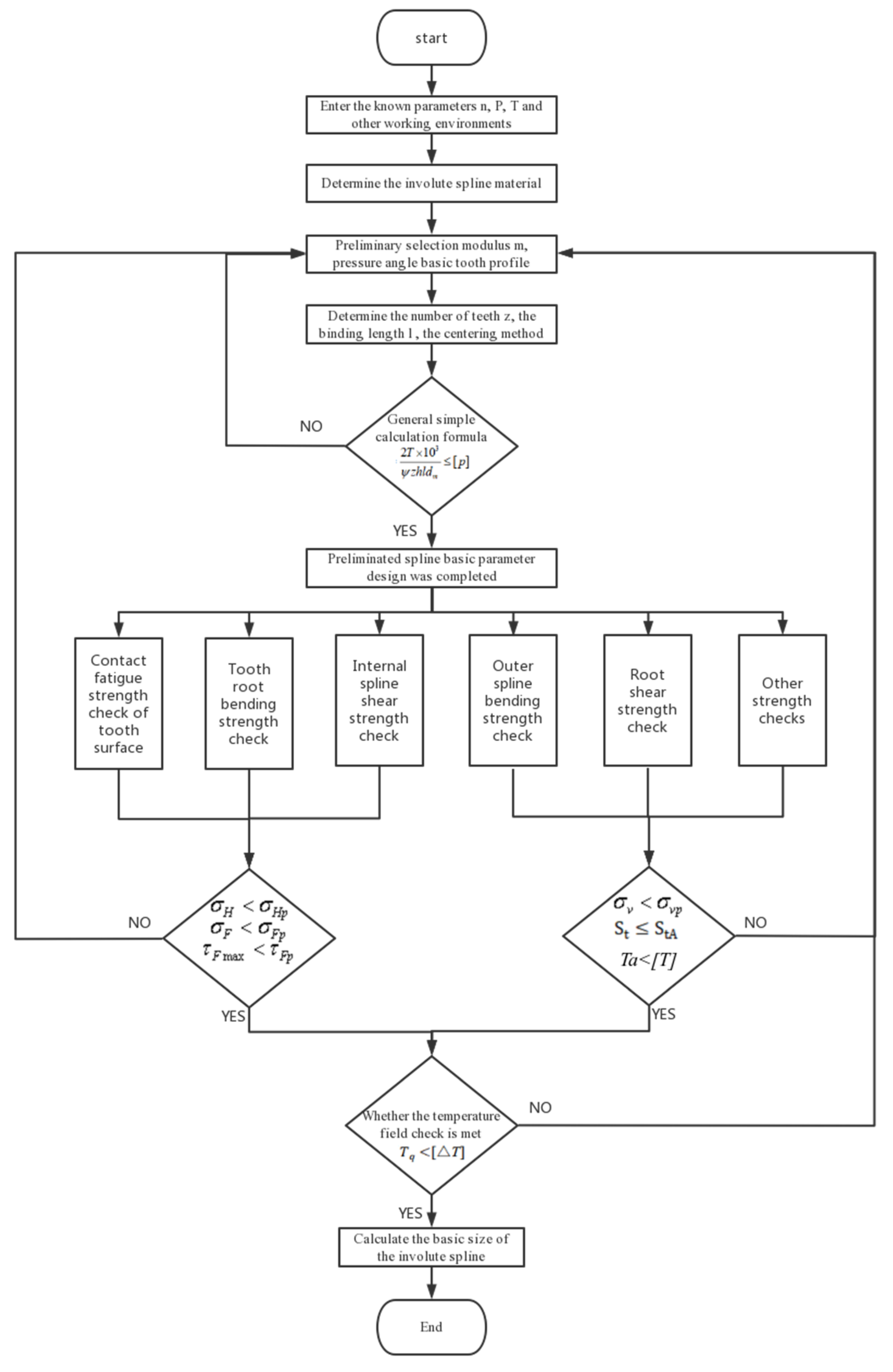
2.1. Involute Splines Parameter Design
2.1.1. Basic Tooth Profile and Pressure Angle Determination
2.1.2. Selection of Modulus
2.1.3. Determination of the Engagement Length
2.1.4. Determination of the Number of Teeth
2.1.5. Selection of Centering Method
2.1.6. Analysis of the Calculation Results of Basic Parameters
2.2. Involute Splines Strength Checking
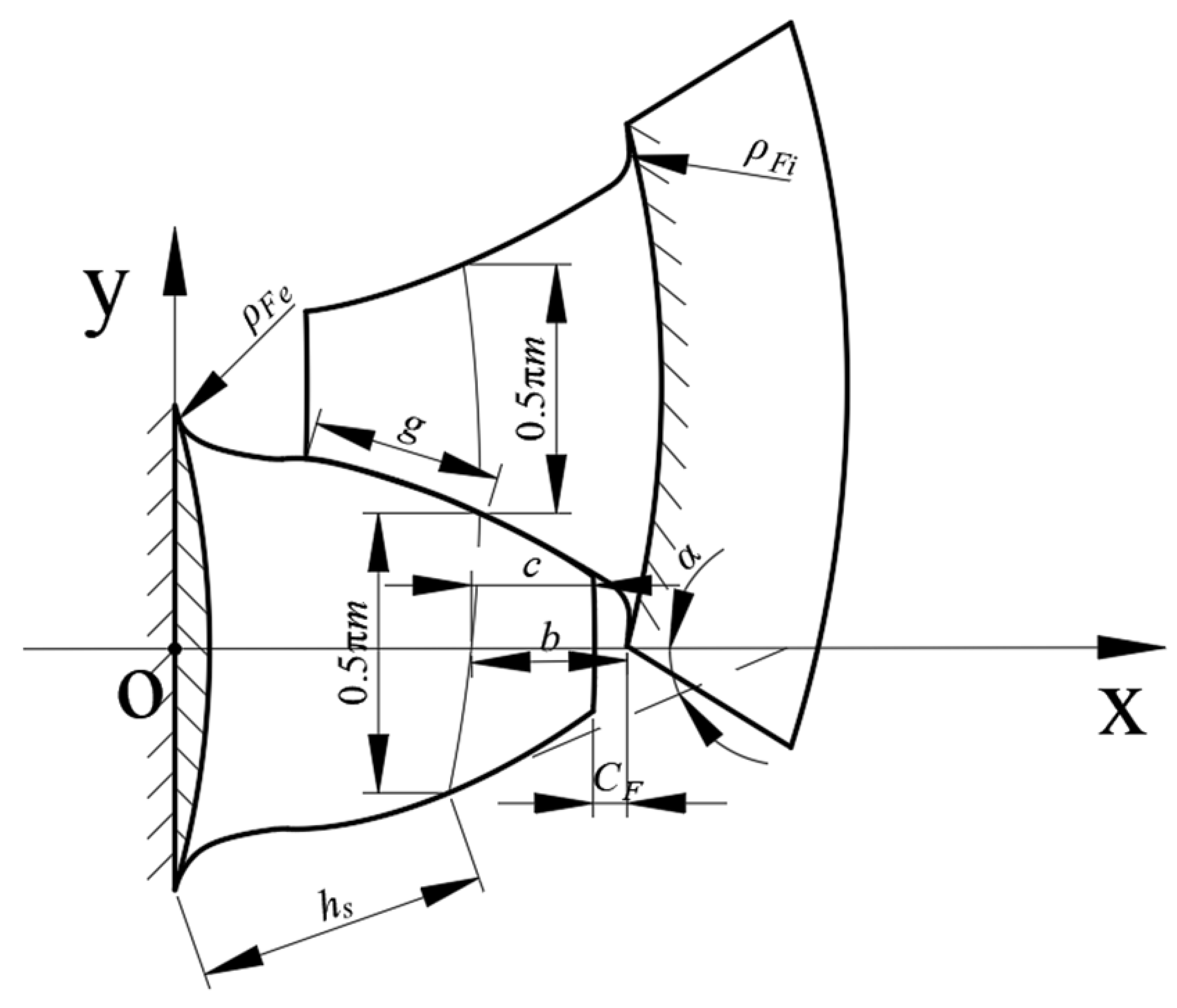
2.2.1. Shear Strength Check of Internal Splines
2.2.2. Other Strength Calculations
- (1)
- Calculation of wear resistance when operating at 108 cycles:
- (2)
- Calculation of wear resistance during long-term operation:
2.2.3. Allowable Torque Calibration
2.3. Temperature Field Calibration
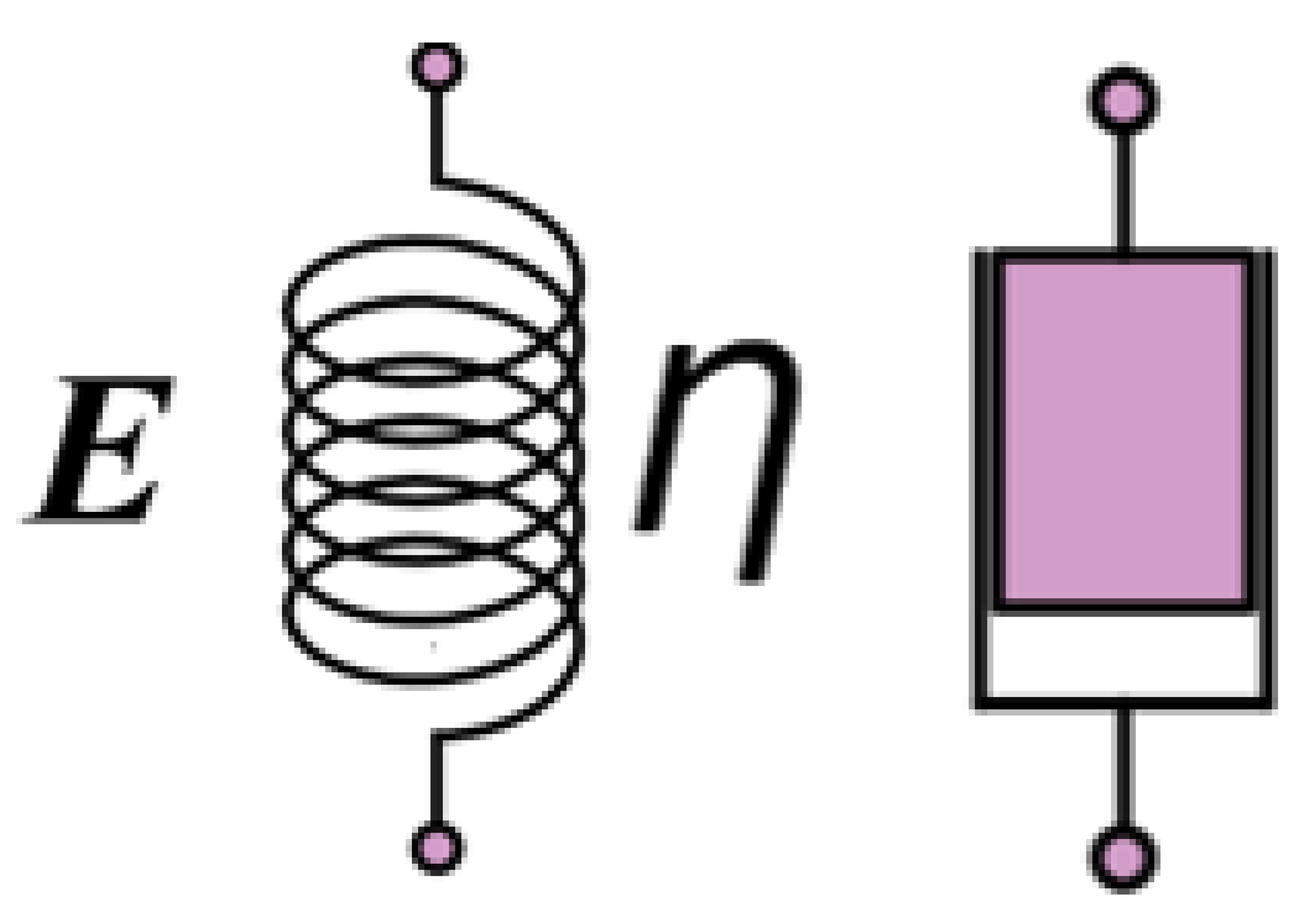
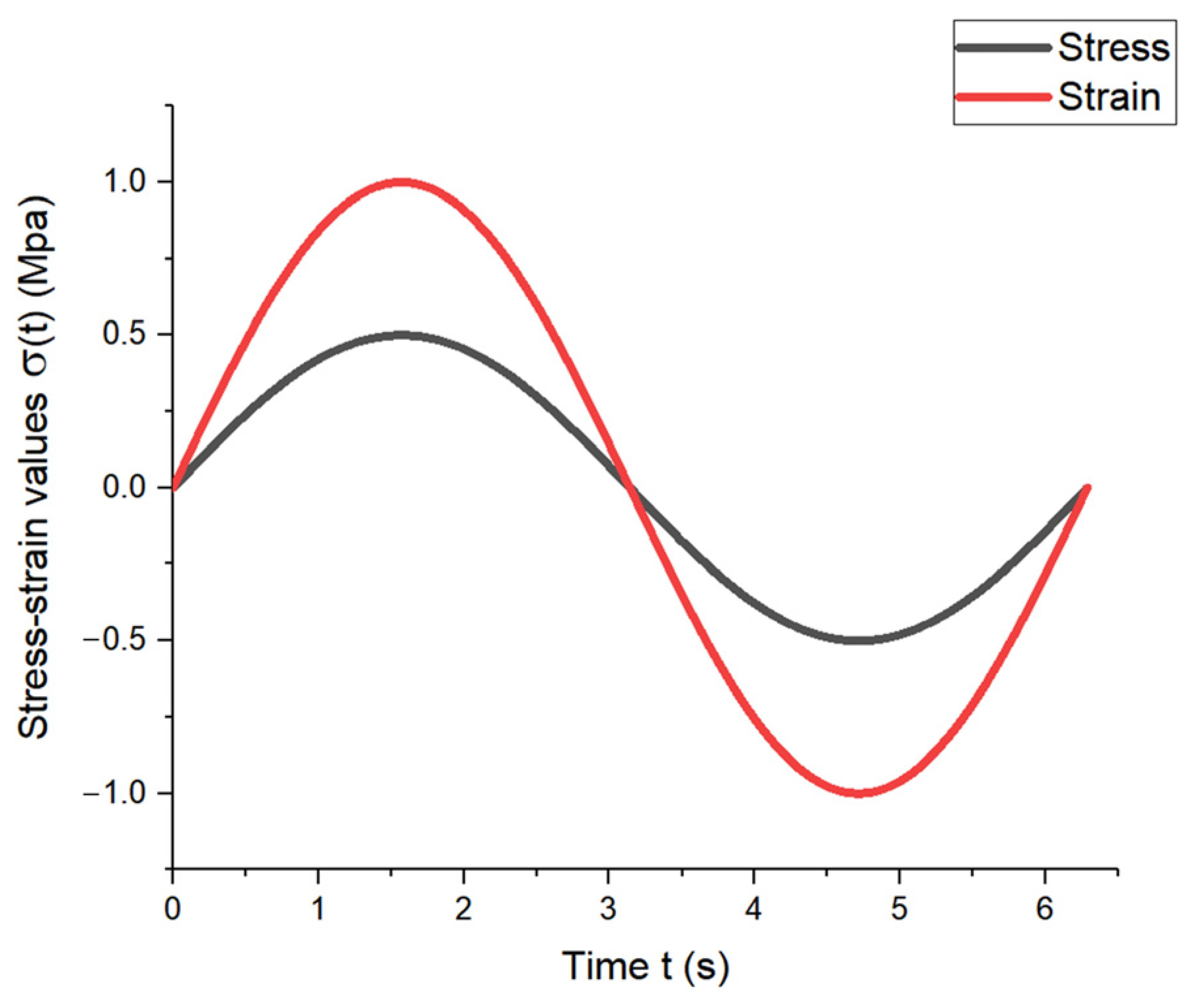
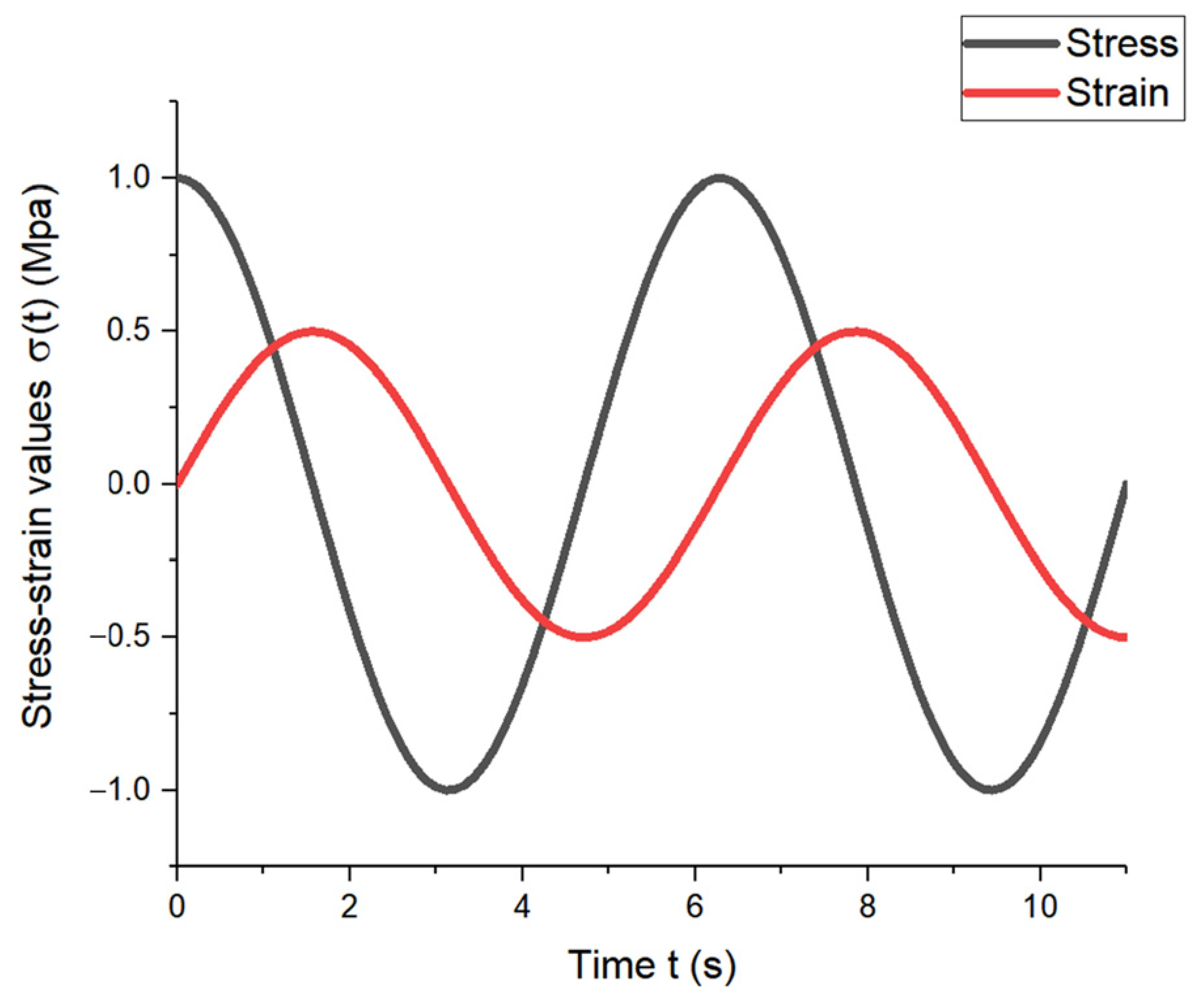
Stress-Strain Relationships for PEEK-Based Materials
2.4. Analysis of Strength Calculation Results
3. Contact Characteristics Analysis
3.1. Solid Modeling of Involute Splines
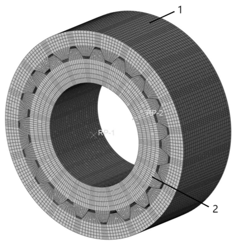
3.2. Finite Element Modeling of Involute Splines
3.3. Simulation Results and Analysis
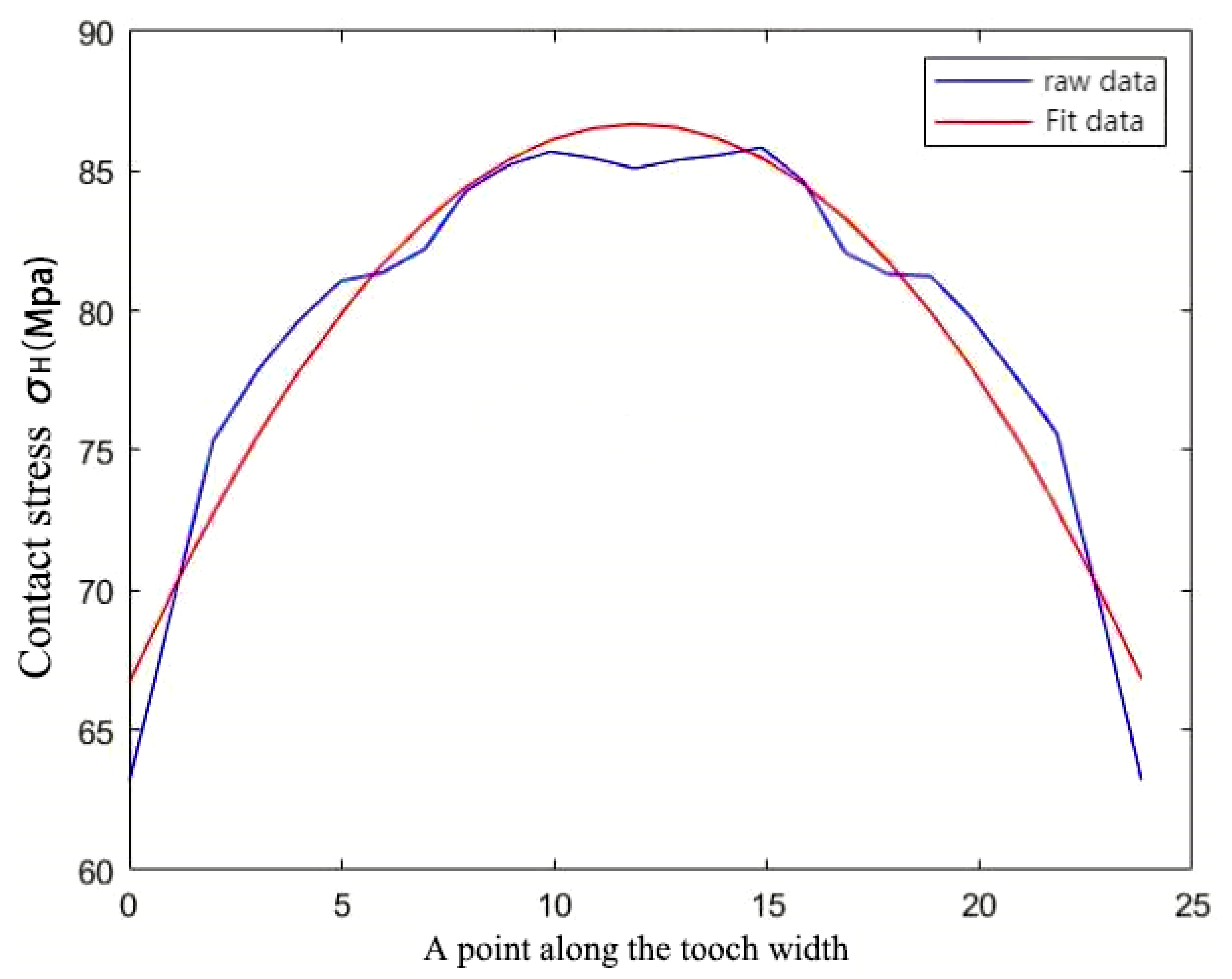
3.3.1. Tooth Surface Contact Compressive Stresses
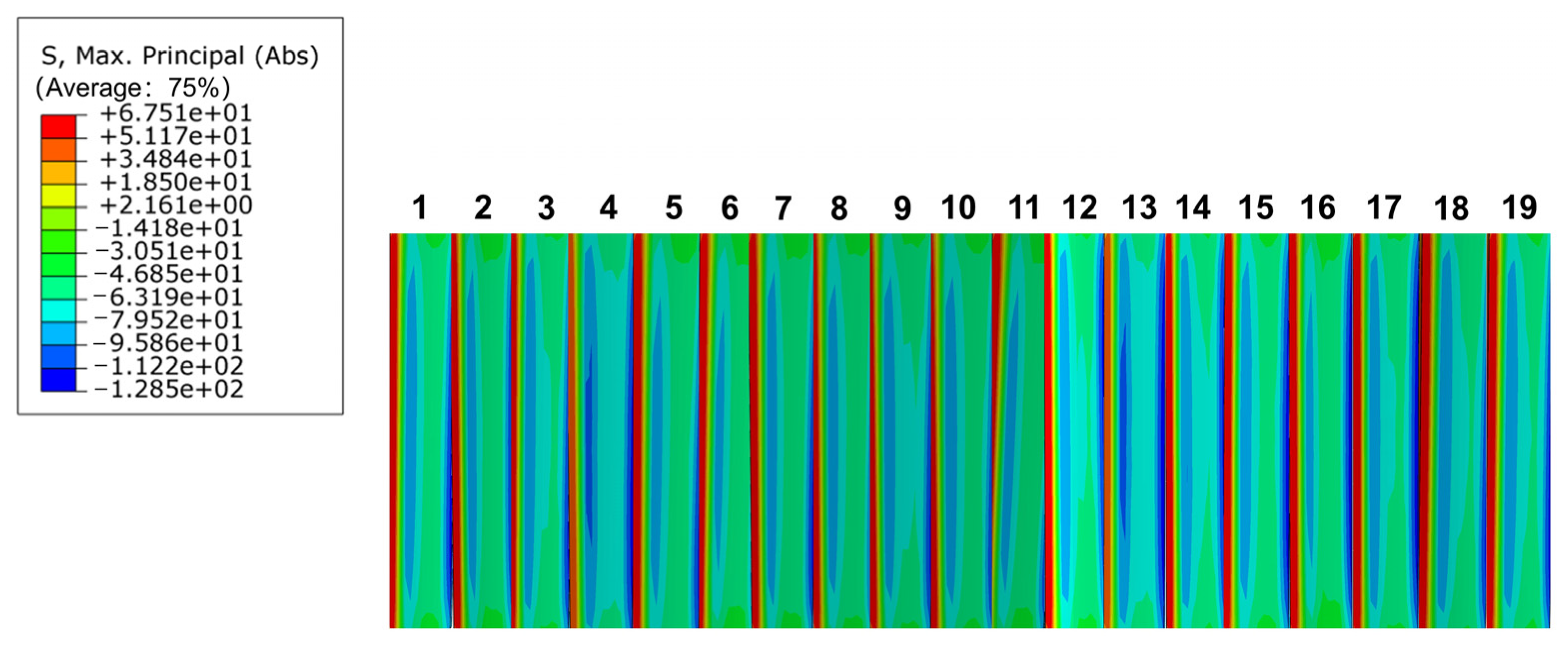
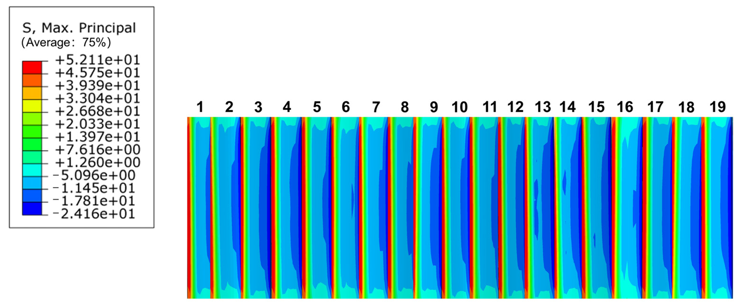
3.3.2. Tooth Root Bending Stress Distribution
4. Parameter Optimization Design
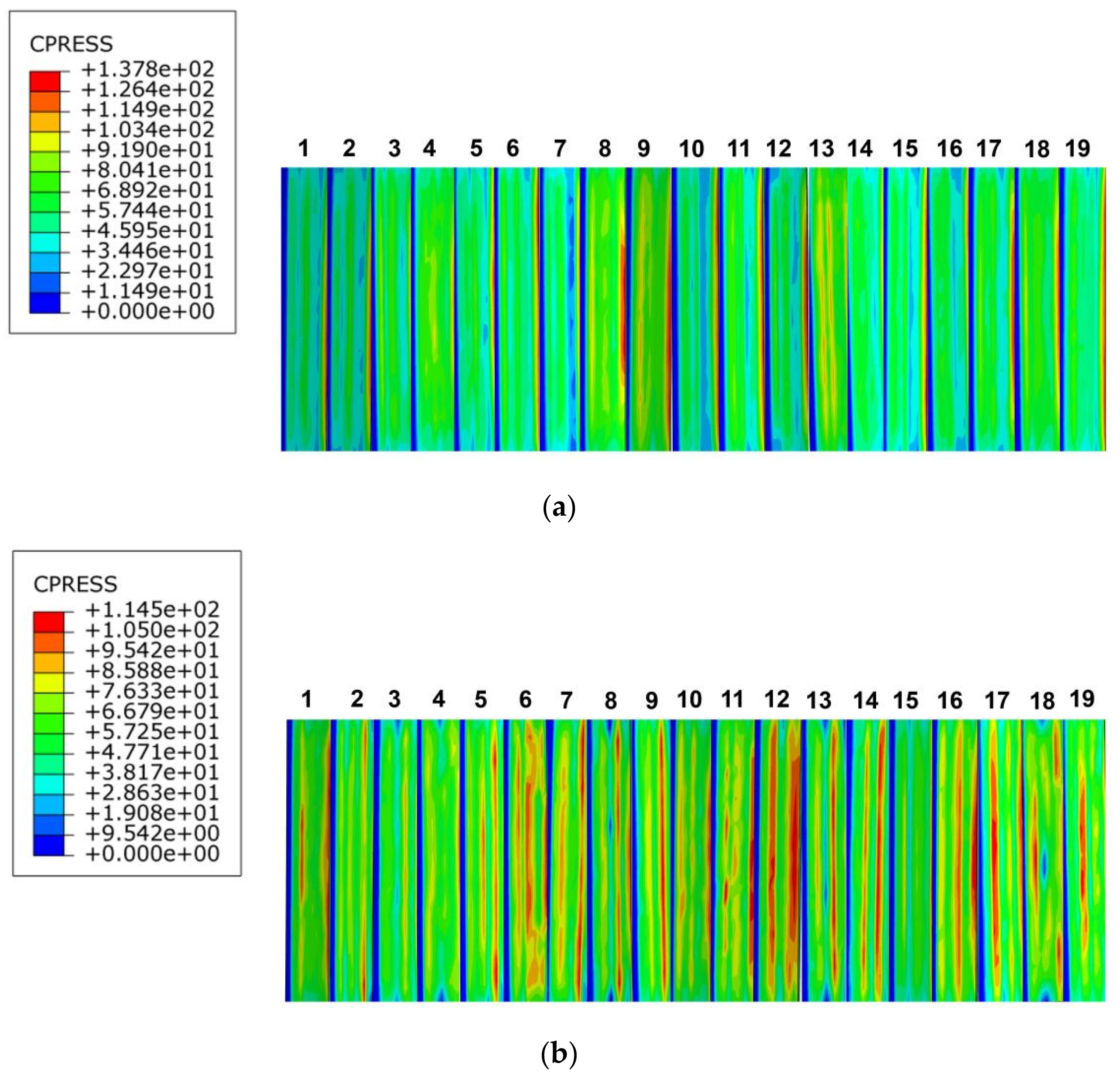
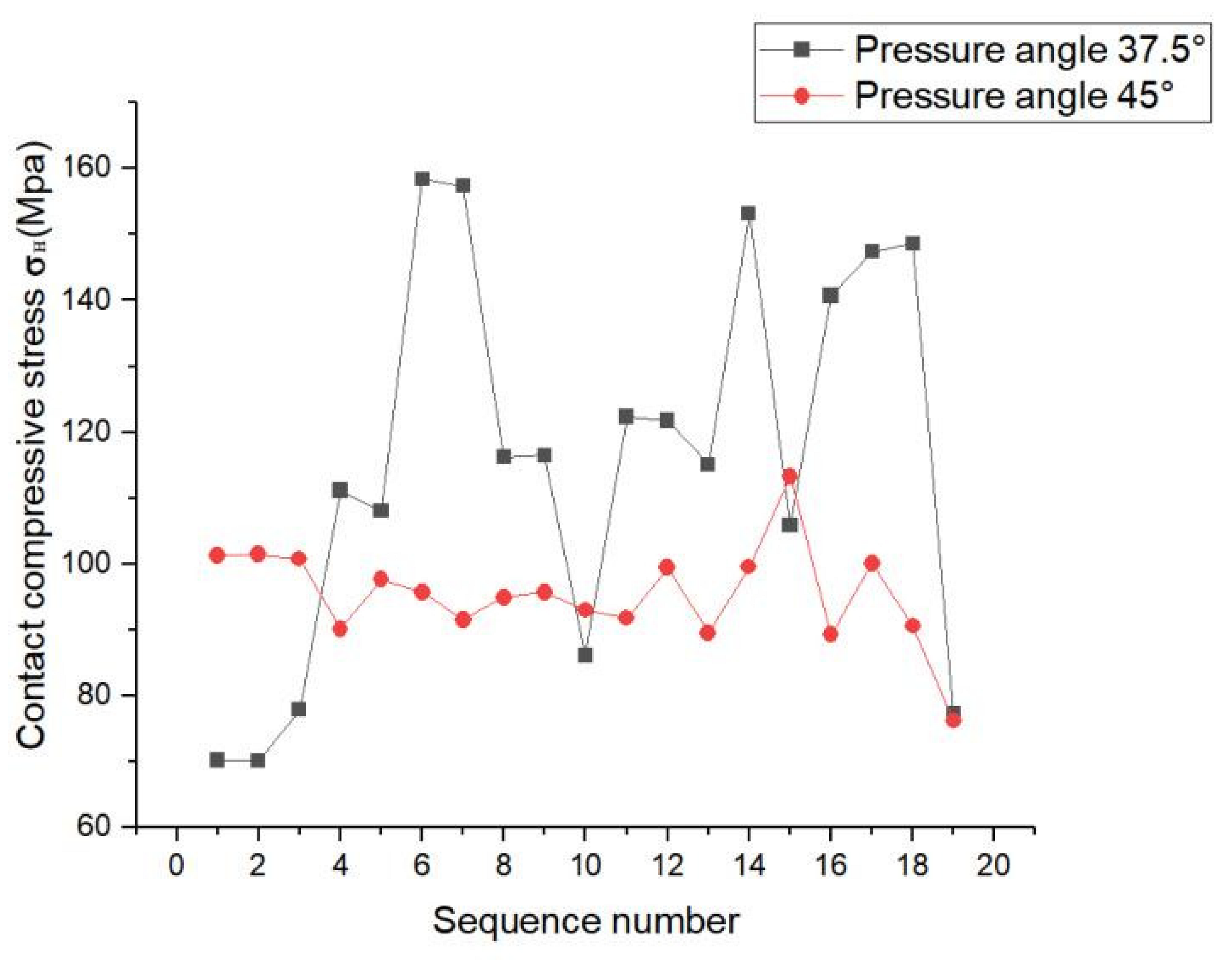
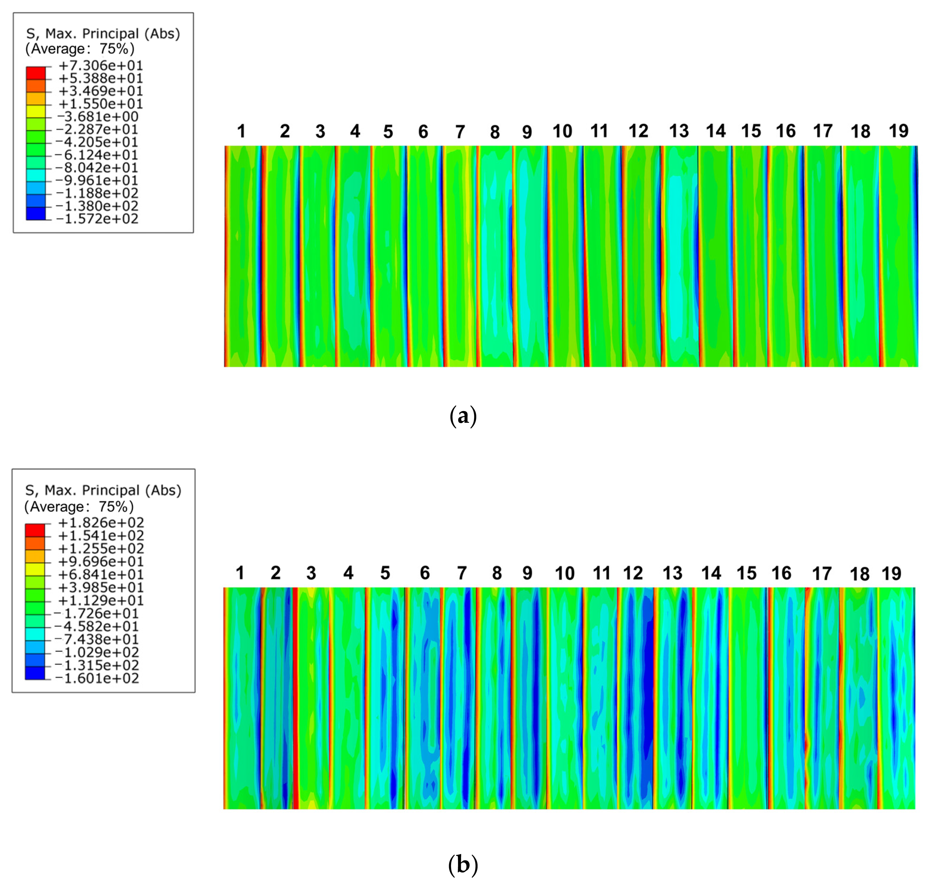
4.1. Analysis of the Effect on Splines Contact Characteristics at Different Pressure Angles
4.2. Analysis of the Effect on Splines Contact Characteristics at Different Modulus
4.3. Analysis of the Effect on Splines Contact Characteristics at Different Engagement Length
5. Conclusions
- (1)
- Under given working conditions, according to the PEEK-based material involute splines design theory and strength check method proposed in this study, involute splines were developed using PEEK5600CF30 material. The PEEK5600CF30 material-based involute splines were calibrated for tooth contact strength, tooth root bending strength, tooth root shear strength, outer spline torsion and bending resistance, inner spline shear strength, allowable torque calibration, temperature field analysis, and other strengths. The results satisfied the working requirements and were consistent with the finite element simulation results. This provides a good theoretical basis for the application of involute splines in PEEK-based materials.
- (2)
- The effect of viscoelasticity on the temperature state of the PEEK-based involute splines was more pronounced, and the results were more accurate and reliable when considering the viscoelasticity of the temperature field calibration. This conclusion is crucial for improving the contact characteristics and durability of splines and has a good reference value for engineering practice.
- (3)
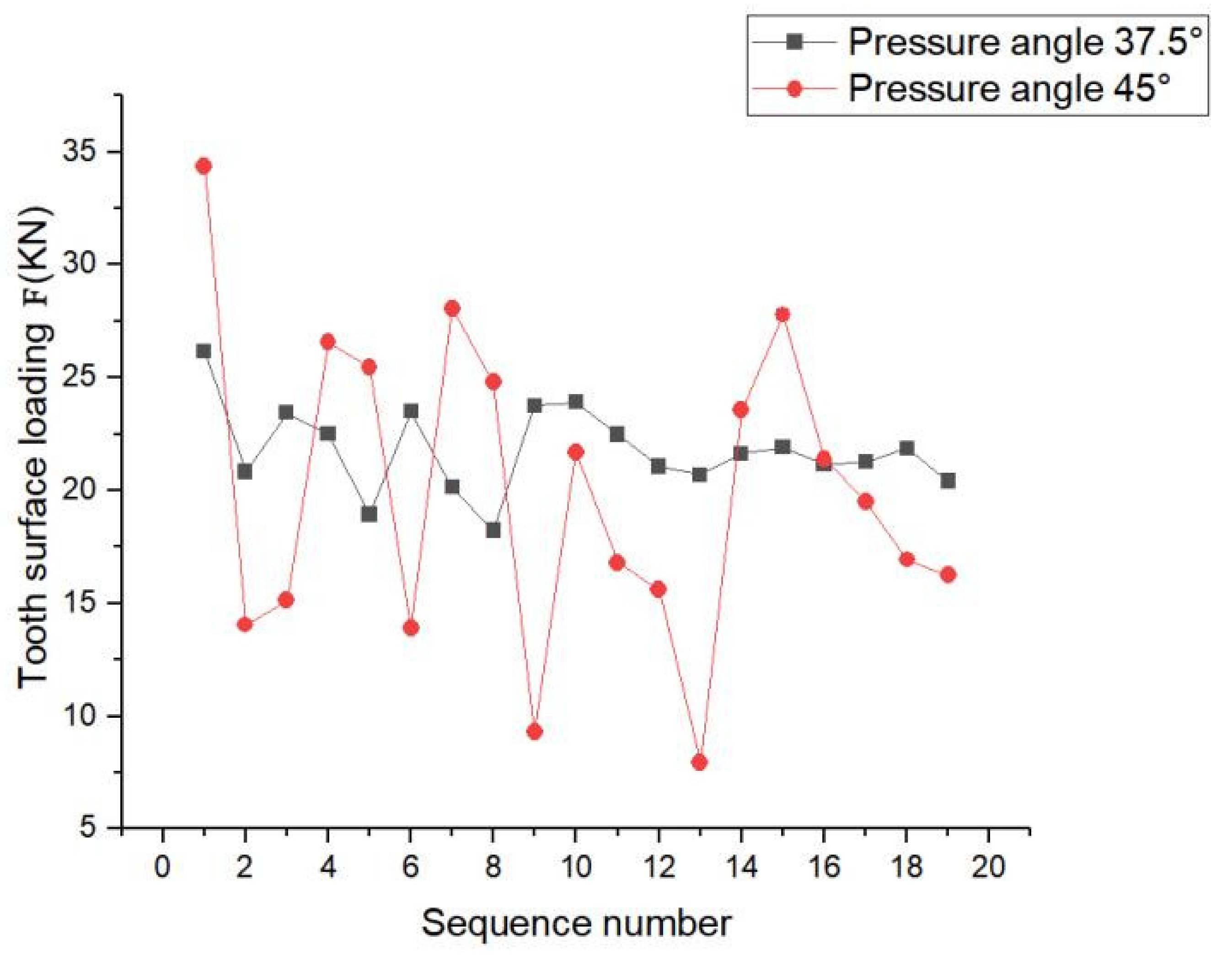
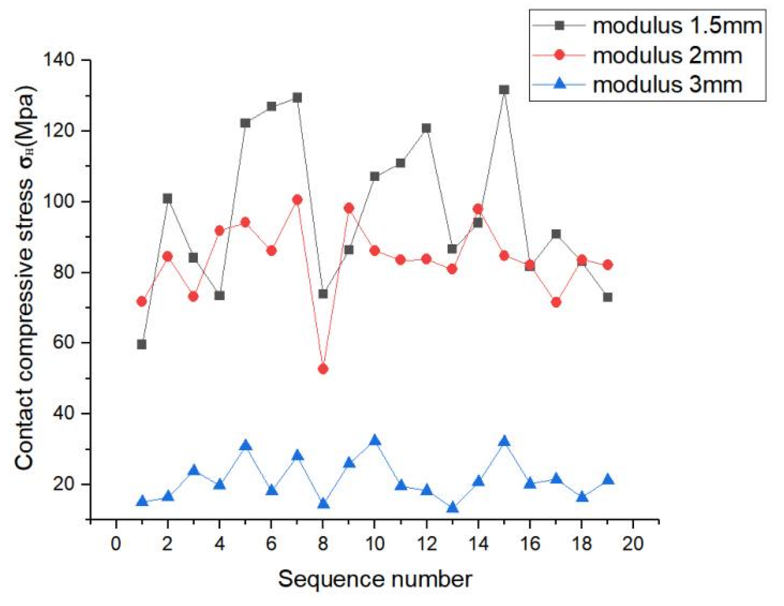
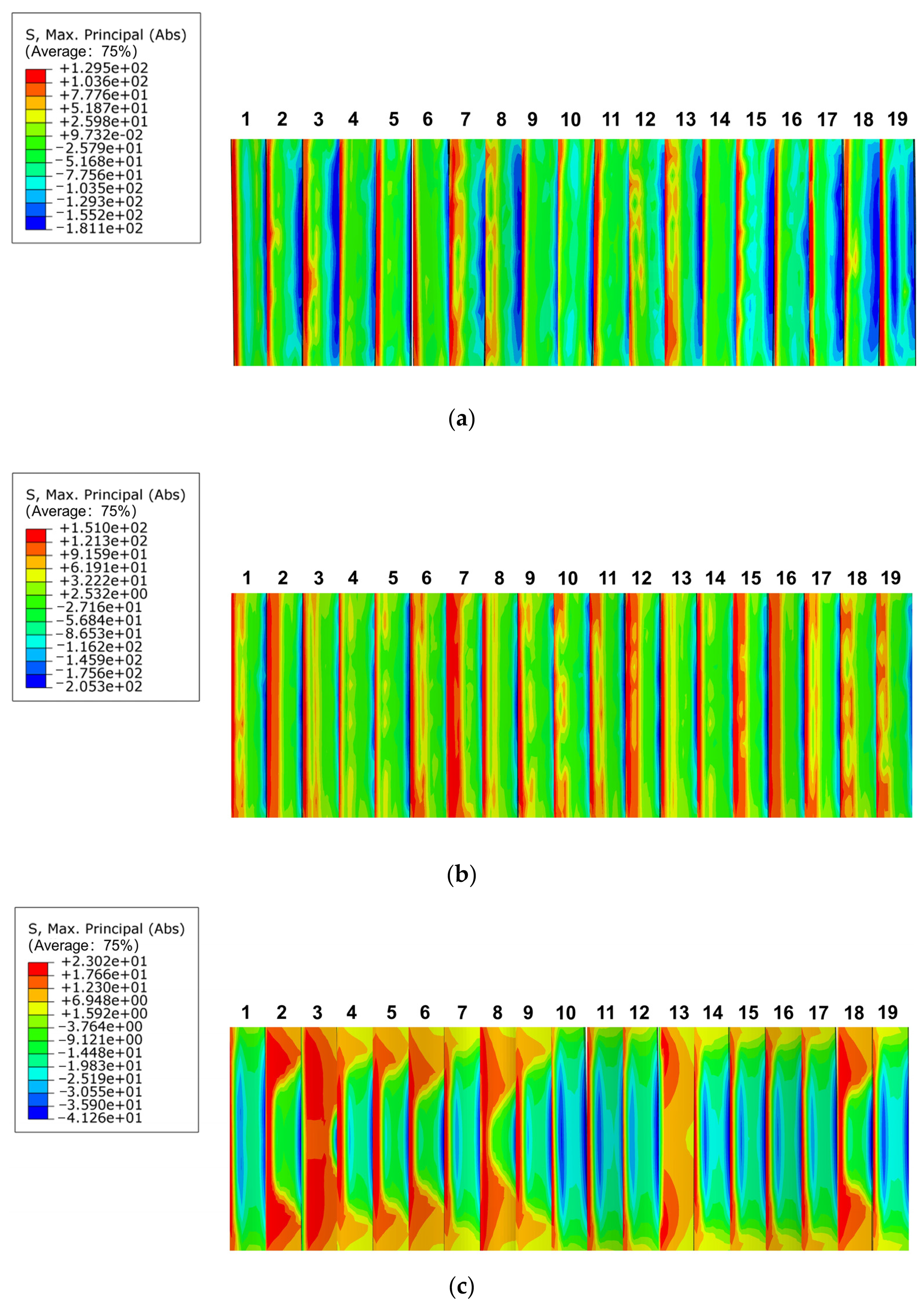
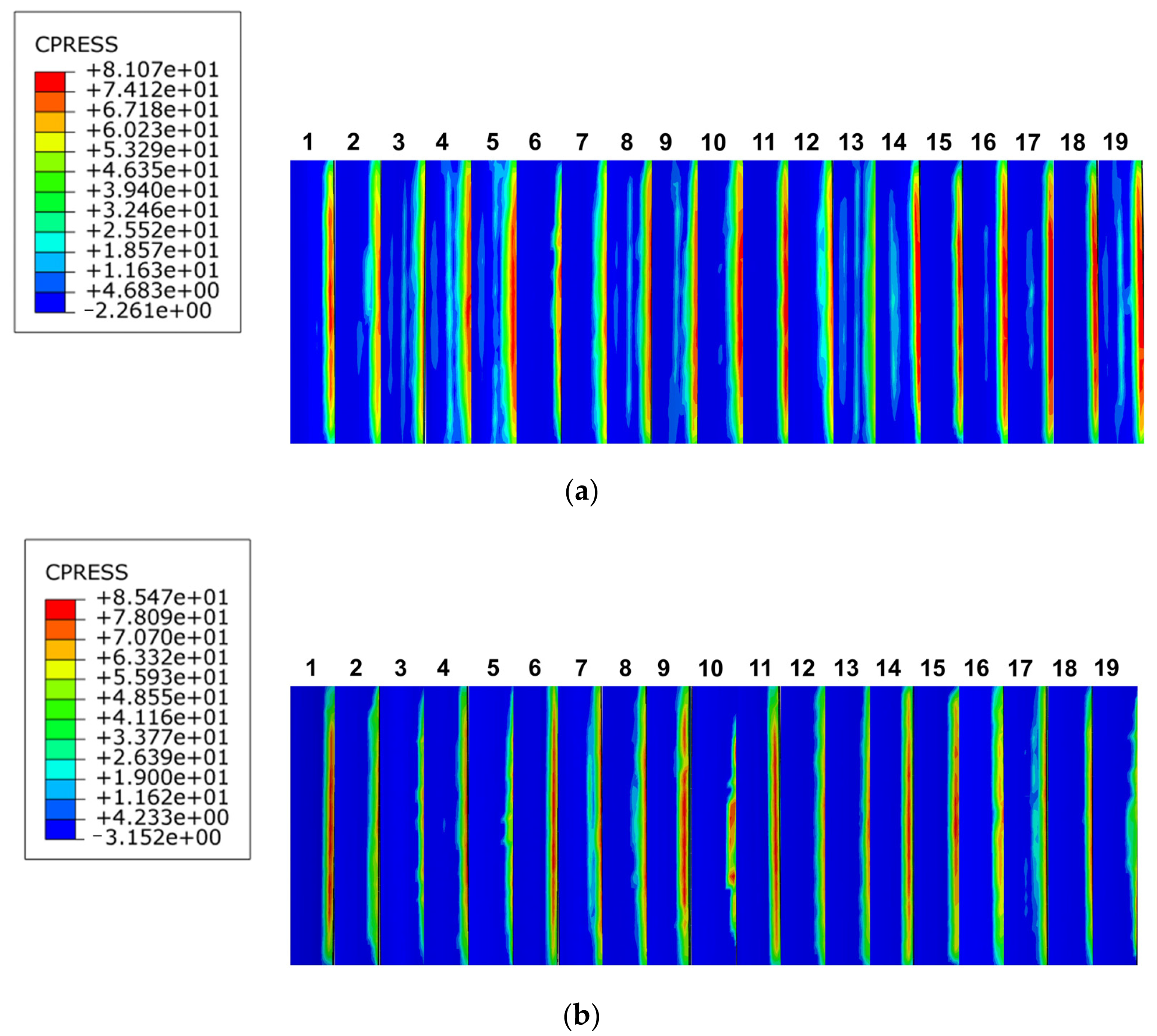
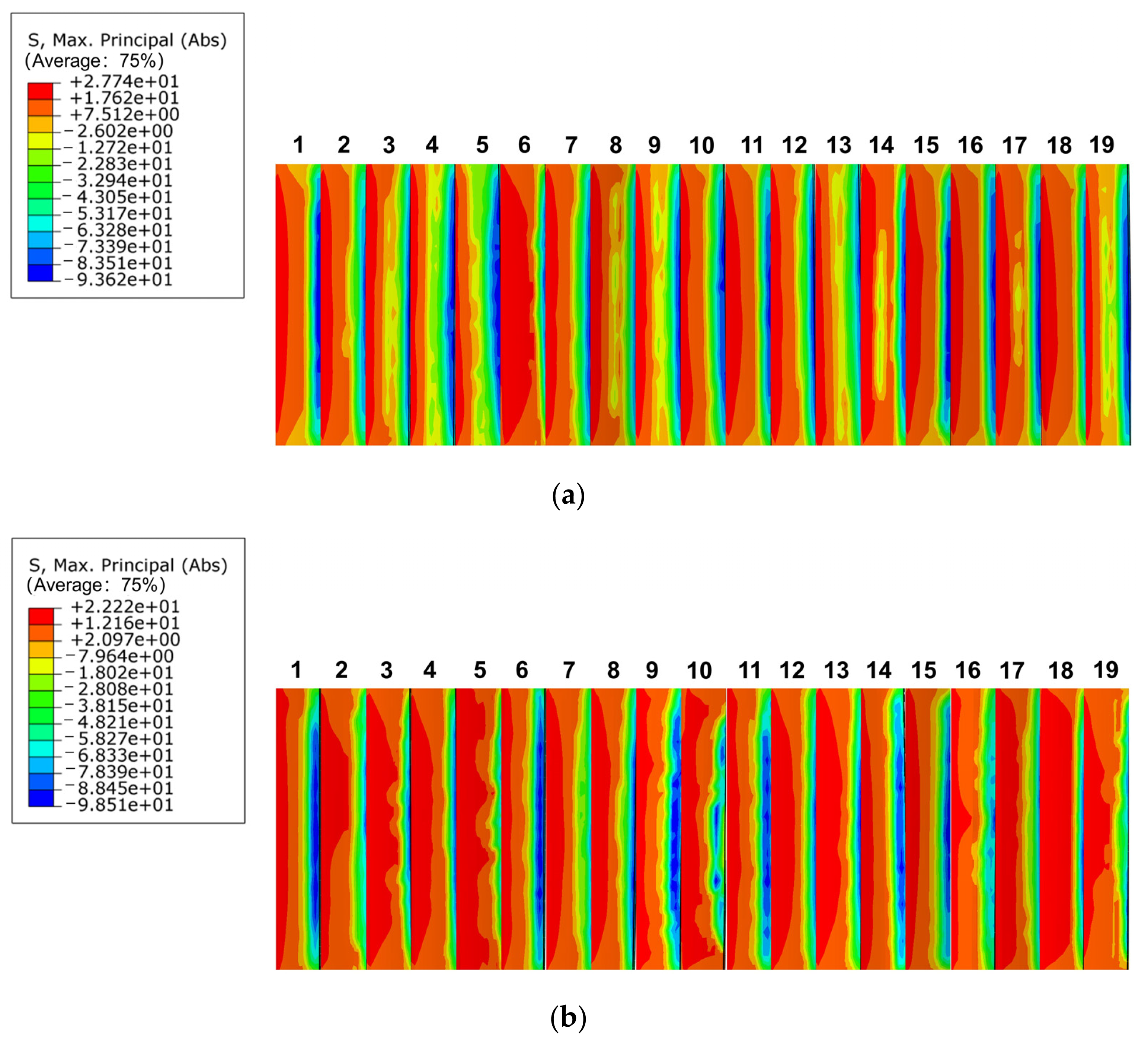
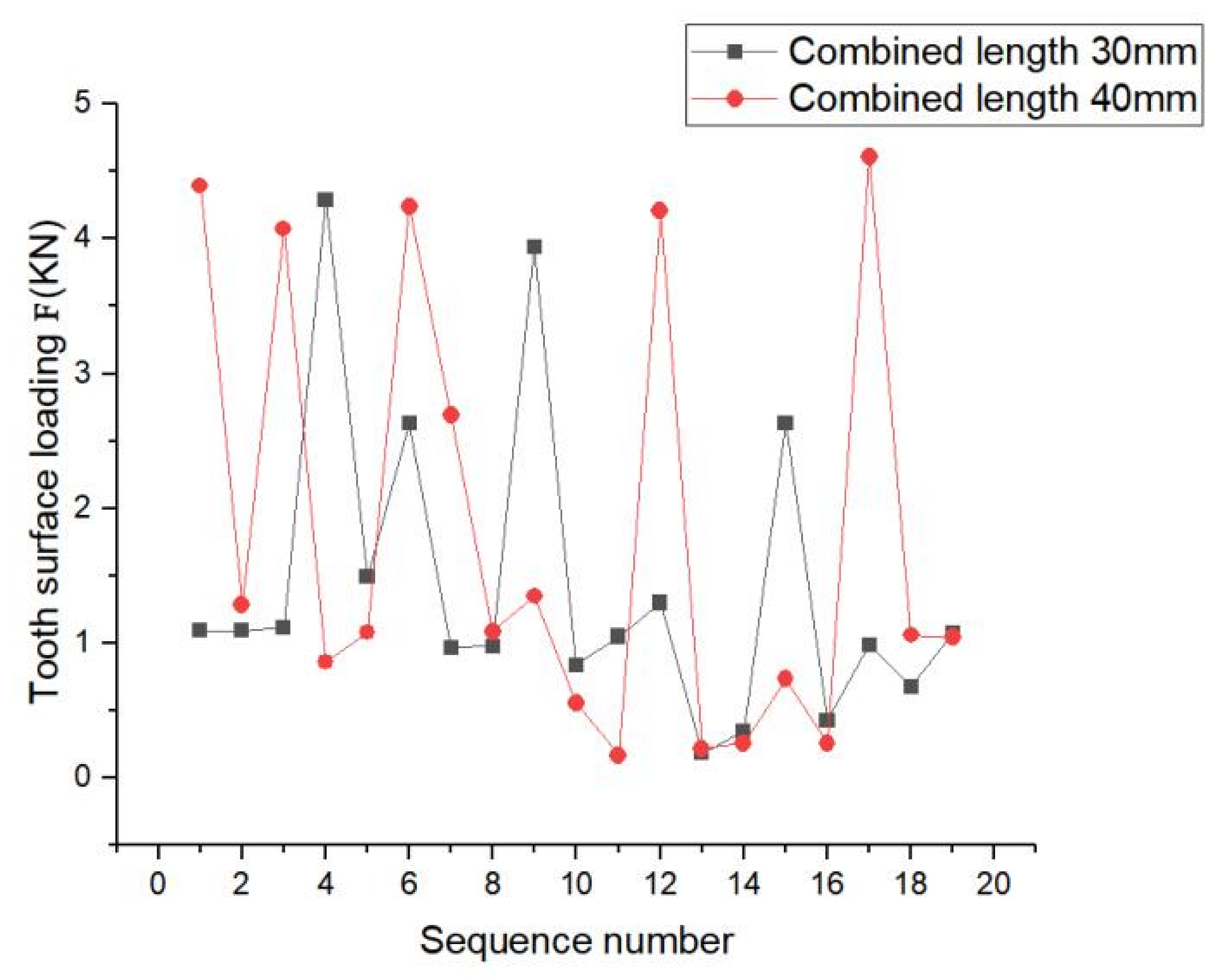
- Based on the working conditions in 2.1.6, finite element analysis was performed for the designed splines. Under the condition that other parameters remained unchanged, the involute splines showed better tooth surface compressive stress at a pressure angle of 45° than that at 37.5°; also, the amplitude of its tooth surface contact compressive stress distribution decreased and was more uniform. The stress concentration phenomenon was obvious in the load fluctuation range. Comparing the analysis of involute splines with different moduli, we determined that with increase in modulus, the tooth contact compressive stress became uneven, the maximum contact compressive stress showed a decreasing trend, the value of the maximum stress increased and then decreased, and the load changes were approximately the same. Comparing the analysis of involute splines with different bond lengths, we determined that the tooth contact compressive stress trend remained almost unchanged with increase in bond length, and the load fluctuation range increased with increase in length, and the stress concentration phenomenon improved to some extent.
- (4)
- The bearing capacity of involute spline couplings can be improved by increasing the pressure angle. The appropriate modulus selection can balance the strength and size requirements of the involute spline couplings. Increasing the engagement length of involute spline couplings can increase the contact area and enhance the connection effect of involute spline couplings. It is recommended to increase the engagement length of the involute spline coupling appropriately. In practical applications, it is necessary to select the appropriate parameters, such as pressure angle, modulus, and engagement length, according to the operating environment and bearing requirements of the involute spline couplings to meet the performance requirements of the involute spline couplings. Future development can further study the optimization of involute spline couplings materials. Through the improvement and upgrading of materials, it can improve the wear resistance, corrosion resistance, fatigue resistance, and other key properties of the involute spline couplings so as to improve the overall performance of the involute spline couplings, which can effectively improve the performance of the transmission system. This has very practical significance.
Author Contributions
Funding
Institutional Review Board Statement
Informed Consent Statement
Data Availability Statement
Conflicts of Interest
Appendix A
Appendix B
| Project | Unit | PEEK5600CF30 |
|---|---|---|
| Tensile strength (23 °C) | MPa | 230 |
| Tensile modulus (23 °C) | GPa | 23.8 |
| Tensile elongation (23 °C) | % | 1.5 |
| Bending strength (23 °C) | MPa | 360 |
| Flexural modulus (23 °C) | GPa | 22.1 |
| Compressive strength (23 °C) | MPa | 280 |
| Tensile strength | MPa | 100 |
| Lzod Impact strength (no notch) | KJ/m2 | 41 |
| Poisson’s ratio | 0.35 | |
| Rockwell hardness | HRR | 123 |
| Coefficient of friction | μ | 0.27 |
| Melting index | g/10min | 3.5 |
| Melting point | °C | 343 |
| Heat deflection temperature | °C | 325 |
| Continuous use temperature | °C | 260 |
| Thermal conductivity | W/(m·k) | 0.3 |
| Elastic modulus | GPa | 3.5 |
| Density | g/(cm)3 | 1.4 |
| Than hot melt | KJ/(Kg°C) | 1340 |
References
- Wang, W.Z.; Tu, S.; Liu, S.W. Failure Cases Analysis in Aerospace Field. J. Mater. Sci. Forum 2020, 993, 1277–1285. [Google Scholar]
- Boyce, M.P. The Gas Turbine Engineering Handbook, 3rd ed.; Gulf Professional Publishing: Boston, MA, USA, 2006. [Google Scholar]
- Monti, S.; Guagliano, M. Failure analysis of an involute spline coupling of an overhead bridge crane. Eng. Fail. Anal. 2019, 104, 321–330. [Google Scholar] [CrossRef]
- Zorko, D.; Kulovec, S.; Duhovnik, J.; Tavčar, J. Durability and design parameters of a Steel/PEEK gear pair. Mech. Mach. Theory 2019, 140, 825–846. [Google Scholar] [CrossRef]
- Leen, S.B.; Richardson, I.J.; McColl, I.R.; Williams, E.J.; Hyde, T.R. Macroscopic fretting variables in a splined coupling under combined torque and axial load. J. Strain Anal. 2001, 36, 481–497. [Google Scholar] [CrossRef]
- Leen, S.B.; Hyde, T.H.; Ratsimba, C.H.H.; Williams, E.J.; Mccoll, I.R. An investigation of the fatigue and fretting performance of a representative aero-engine spline coupling. J. Strain Anal. Eng. Des. 2002, 37, 565–583. [Google Scholar] [CrossRef]
- Leen, S.B.; McColl, I.R.; Ratsimba, C.H.H.; Williams, E.J. Fatigue life prediction for a barrelled spline coupling under torque overload. Proc. Inst. Mech. Eng. G J. Aerosp. Eng. 2003, 217, 123–142. [Google Scholar] [CrossRef]
- Patil, S.B.; Patil, S.R. Experimental and numerical analysis of a load distribution along the length of contact in involute spline shaft. Int. J. Adv. Technol. Eng. Explor. 2019, 6, 30–44. [Google Scholar] [CrossRef]
- Bildyuk, N.A.; Rak, A.A.; Turkina, N.R.; Shashurin, A.E. Analysis of Carrying Capacity of Cogged Spline Connection of Hub-Shaft. Bull. Educ. Sci. Dev. Russ. Acad. Nat. Sci. 2021, 25, 28–34. [Google Scholar]
- Volfson, B.P. Stress sources and critical stress combinations for splined shaft. J. Mech. Des. 1982, 104, 551–556. [Google Scholar] [CrossRef]
- Duo, L.S.; Wallen, R.; Errichello, R.; Keller, J.A. Theoretical and experimental study on gear-coupling contact and loads considering misalignment, torque, and friction influences. Mech. Mach. Theory 2016, 98, 242–262. [Google Scholar]
- Vinaud, F.J.; Bosqueiro, T.D.A. Non-Linear Finite Element Analysis of an Open Spline Connection. In Proceedings of the 24th Reliability, Stress Analysis, and Failure Prevention Conference (RSAFP), Online, 17–19 August 2020; Volume 5. [Google Scholar]
- Oleg, L.; Pyndus, Y.I.; Lutsiv, I.; Vovk, Y.; Poberezhna, L.; Tretiakov, O.A.; Zolotyy, R. Fracture cause analysis of the extruder’s shaft and geometry optimization of the spline. J. Mech. Eng. Sci. 2019, 13, 4449–4460. [Google Scholar]
- Mukhirmesh, K.H.; Waleed, K.J. A Spline Shape Deep Drawing using Finite Element Simulation and Experimental Work Test. IOP Conf. Ser. Mater. Sci. Eng. 2021, 1094, 012132. [Google Scholar] [CrossRef]
- Stenstrand, A. Spline Optimization Tool Using Finite Element Analysis. Master’s Thesis, Chalmers University of Technology, Gothenburg, Sweden, 2018. [Google Scholar]
- Chen, Y.C.; Yun, H.C.; Jui, T.T.; Kun, J.H. Tooth Geometry Design and Two-Dimensional Finite Element Analysis for a Strain Wave Gear with Double-Circular-Arc Profile. Int. Power Transm. Gearing Conf. 2019, 10, V010T11A030. [Google Scholar]
- Han, Z.B. Analysis of Contact Characteristics of Involute Spline in Wind Power Transmission. Master’s Thesis, Chongqing University, Chongqing, China, 2018. [Google Scholar]
- Yu, S.T.; Lan, H.Q.; Cai, J.B. Simulation Study on Fretting Wear of Aviation Involute Spline. J. Surf. Technol. 2022, 51, 149–156. [Google Scholar]
- Mao, K.; Chetwynd, D.G.; Millson, M. A new method for testing polymer gear wear rate and performance. J. Polymer Test. 2020, 82, 106323. [Google Scholar] [CrossRef]
- Qureshi, W.A.; Curà, F.; Mura, A. Prediction of fretting wear in aero-engine spline couplings made of 42CrMo4. J. Proc. Inst. Mech. Eng. C J. Mech. Eng. Sci. 2017, 231, 4684–4692. [Google Scholar] [CrossRef]
- Curà, F.; Mura, A.; Adamo, F. Methodology development to design a representative test specimen for wear damage in spline couplings. Procedia Struct. Integr. 2018, 8, 204–211. [Google Scholar] [CrossRef]
- Wang, T.Y. Contact Stiffness and Rotor Dynamic Characteristics of Spline Connection Structure. Master’s Thesis, Dalian University of Technology, Dalian, China, 2021. [Google Scholar]
- Nikolaev, I.; Leontiev, M.; Popov, V. Spline coupling in the rotor dynamics problems of a gas turbine engine. J. Eng. J. Sci. Innov. 2023, 9, 141. [Google Scholar] [CrossRef]
- Faidh-Allah, M.H.; Amjed, Z.; Khalik, A. Experimental and Numerical Stress Analysis of Involute Splined Shaft. J. Eng. 2023, 18, 415–422. [Google Scholar] [CrossRef]
- Pardhi, D.G.; Khamankar, S.D. Stress Analysis of Spline Shaft Using Finite Element Method and Its Experimental Verification by Photo Elasticity. Int. J. Mech. Eng. Robot. Res. 2014, 3, 451. [Google Scholar]
- Cheng, D.X. Handbook of Mechanical Design; Chemical Industry Press: Beijing, China, 2008. [Google Scholar]
- ISO 4156. 1. 2. 3-2005; Straight Cylindrical Involute Splines. ISO Copyright Office: Geneva, Switzerland, 2015.
- ANSI AGMA 6123-C16. Design Manual for Enclosed Epicyclic Gear Drives. American Gear Manufacturers Association: Alexandria, VI, USA, 2016.
- Huo, Q.X. Study on Nonlinear Dynamic Meshing Force of Involute Spline Couplings in Aero-Engine with Misalignment. Master’s Thesis, Shaanxi University of Science and Technology, Xi’an, China, 2020. [Google Scholar]
- Liu, X.L. Discussion on the Allowable Bearing Stress of Key Joint. Mech. Eng. Autom. 2010, 183–184, 186. [Google Scholar]
- Xue, X.Z.; Wang, S.M.; Yuan, R. Nonlinear dynamic characteristics of involute spline couplings. J. Harbin Inst. Technol. 2015, 47, 107–111. [Google Scholar]
- DIN5480-1; Involute Splines Based on Reference Diameters. NAM: Köln, Germany, 2006.
- Zhang, L. Composite Gears; Tsinghua University Press: Beijing, China, 2012. [Google Scholar]
- Cui, Y.C.; Zhang, H.Y.; Cui, L.X. Pei Dian Sheji Shouce; China Electric Power Press: Beijing, China, 2015. [Google Scholar]
- Johnson, K.L. Contact Mechanics. J. Tribol. 1985, 108, 464. [Google Scholar]
- Xiao, L. Analysis and Confirmation Techniques for Requirements of Temperature Environmental Worthiness of Aircraft. Equip. Environ. Eng. 2008, 5, 60–64. [Google Scholar]
- Xiao, L.; Xu, Y.Q.; Chen, Z.Y.; Sun, X.W.; Xu, H. Prediction of fretting damage and wear fatigue of floating involute spline couplings. Xibei Gongye Daxue Xuebao J. Northwest. Polytech. Univ. 2022, 40, 549–559. [Google Scholar] [CrossRef]
- Ma, D.Q.; Ye, Z.F.; Feng, Q.J. Research on contact stress distribution and meshing position change rule of variable hyperbolic cylindrical gear with arcuate tooth trace. Manuf. Technol. Mach. Tool 2019, 9, 53–58. [Google Scholar] [CrossRef]
- De Caires, B.J. Variation Analysis of Involute Spline Tooth Contact. Master’s Thesis, Brigham Young University, Provo, UT, USA, 2006. [Google Scholar]








| Symbol | Variable | Value |
|---|---|---|
| z | Number of teeth | 19 |
| m | Modulus (mm) | 2.5 |
| αD | Pressure angle (°) | 30 |
| l | Engagement length (mm) | 23.75 |
| Tooth profile | The root of the tooth is round | |
| D | Reference diameter (mm) | 47.5 |
| Symbol Description | Takes Values | Symbol Description | Takes Values |
|---|---|---|---|
| Coefficient of safety for tooth contact strength SH | 1.35 | Mechanical equivalent of heat J (J/Kcal) | 4.2 |
| Utilization factor K1 | 1 | Poisson’s ratio V | 0.35 |
| Tooth side clearance coefficient | 1 | Rockwell hardness C | 123 |
| Distribution coefficient | 1 | Friction coefficient μ | 0.27 (μ) |
| Axial load factor | 1.6 | Melting point T (°C) | 343 |
| Conversion factor K | 0.3 | Thermal conductivity λ (W/(m·k)) | 0.3 |
| Lewisian Factor Y | 1.5 | Modulus of elasticity E (GPa) | 3.5 |
| Load distribution Coefficient | 1 | Density ν (g/) | 1.4 |
| Uneven factor of load between teeth | 0.75 | Safety factor s | 1 |
| Specific heat c ((KJ/(Kg·°C)) | 1340 |
| Symbol Description | Takes Values | Symbol Description | Takes Values |
|---|---|---|---|
| Contact compressive stress on the tooth surface (MPa) | 80.31 | Allowable shear stress of tooth root (MPa) | 164.69 |
| Allowable compressive stress of tooth surface (MPa) | 243.98 | Equivalent stress (MPa) | 181.47 |
| Tooth root bending stress (MPa) | 1.79 | Allowable equivalent stress (MPa) | 329.38 |
| Permissible bending stress of tooth root (MPa) | 329.38 | Allowable compressive stress of tooth surface (MPa) | 95.00 |
| Tooth root shear stress (MPa) | 153.80 | Allowable compressive stress of tooth surface (MPa) | 36.82 |
| Yield strength σ0.2 (MPa) | 527.00 | Tooth root torsional shear stress (MPa) | 99.13 |
| Break-away stress (MPa) | 19.67 | Maximum torque Ta (N/m) | 1750.83 |
| Tensile tooth bending stress (MPa) | 28.54 | Allowable torque [T] (N/m) | 16,235 |
| Circumferential stress (MPa) | 0.02 | Temperature before engagement Tm (°C) | 86.80 |
| Allowable stress (MPa) | 917.70 | Instantaneous internal consumption temperature rise △Tc (°C) | 6.00 × 10⁻⁵ |
| Total tensile stress (MPa) | 48.23 | Instantaneous frictional temperature rise △Tf (°C) | 10.85 |
| Surface pressure for Hertzian stress (MPa) | 55.95 | Total surface temperature (°C) | 97.65 |
Disclaimer/Publisher’s Note: The statements, opinions and data contained in all publications are solely those of the individual author(s) and contributor(s) and not of MDPI and/or the editor(s). MDPI and/or the editor(s) disclaim responsibility for any injury to people or property resulting from any ideas, methods, instructions or products referred to in the content. |
© 2023 by the authors. Licensee MDPI, Basel, Switzerland. This article is an open access article distributed under the terms and conditions of the Creative Commons Attribution (CC BY) license (https://creativecommons.org/licenses/by/4.0/).
Share and Cite
Xue, X.; Yu, W.; Lin, K.; Zhang, N.; Xiao, L.; Jiang, Y. Design Method and Teeth Contact Simulation of PEEK Involute Spline Couplings. Materials 2024, 17, 60. https://doi.org/10.3390/ma17010060
Xue X, Yu W, Lin K, Zhang N, Xiao L, Jiang Y. Design Method and Teeth Contact Simulation of PEEK Involute Spline Couplings. Materials. 2024; 17(1):60. https://doi.org/10.3390/ma17010060
Chicago/Turabian StyleXue, Xiangzhen, Wei Yu, Kuan Lin, Ning Zhang, Li Xiao, and Yiqiang Jiang. 2024. "Design Method and Teeth Contact Simulation of PEEK Involute Spline Couplings" Materials 17, no. 1: 60. https://doi.org/10.3390/ma17010060
APA StyleXue, X., Yu, W., Lin, K., Zhang, N., Xiao, L., & Jiang, Y. (2024). Design Method and Teeth Contact Simulation of PEEK Involute Spline Couplings. Materials, 17(1), 60. https://doi.org/10.3390/ma17010060


