Article

Kinetics of Martensite/Austenite Decomposition during Tempering of Ultrafine Nano-Bainitic Steels

1
College of Materials and Metallurgy, Guizhou University, Guiyang 550025, China
2
Key Laboratory for Materials Structure and Strength of Guizhou Province, Guiyang 550025, China
*
Author to whom correspondence should be addressed.
Materials 2024, 17(11), 2690; https://doi.org/10.3390/ma17112690
Submission received: 27 March 2024 / Revised: 7 May 2024 / Accepted: 14 May 2024 / Published: 2 June 2024
(This article belongs to the Section Metals and Alloys)

Abstract

:
In this study, the decomposition of a martensite/austenite (M/A) microconstituent in bainitic steels was analyzed using differential scanning calorimetry (DSC) data in conjunction with Kissinger’s and Johnson–Mehl–Avrami–Kolmogorov (JMAK)’s formulas. In bainitic steel subjected to austempering heat treatment, the presence of an M/A microstructure adversely affects the mechanical properties. According to the kinetic equations derived, it is observed that after tempering the sample at 600 °C for 4000 s, the generation of each phase reaches its maximum. The SEM images taken before and after tempering reveal extensive decomposition of the M/A constituent in the microstructure. The proportion of the M/A microstructure decreased significantly from about 10% before tempering to less than 1% after. Additionally, the content of residual austenite also reduced nearly to zero. These observations are consistent with the predictions of the kinetic equations.

1. Introduction

Super-bainite steel, a nanostructured bainite variant known for its exceptional strength and durability, has recently drawn the attention of the scientific community. It was Professor Bhadeshia and team at the University of Cambridge who first introduced this kind of steel. In order to obtain nano-bainite, bainitic steels need to be heated at low temperatures for several hours or even days [1,2]. Distinctively, unlike other high-strength steels [3,4], ultra-fine nano-bainite steels can be fabricated without the need for costly alloying elements, swift heat treatments, or complex machining [5,6], thereby making them a favored option in numerous mechanical industries [7]. However, the bainite phase transition can be accelerated by optimizing the alloying composition, which includes adding Co and Al elements [8,9]. Depending on the austempering heat treatment used, the untransformed austenite in the bainite transformation structure can be categorized as thin, powdery, or massive [10]. Some of the coarse retained austenite blocks, due to its instability [11,12], transforms into a martensite and austenite (M/A) composition during the cooling process following austempering heat treatment. The M/A island comprises martensite and some residual untransformed austenite interspersed among the bainitic structures [13,14]. The M/A microstructure, characterized by its brittleness, can induce high-stress concentrations under severe deformation, leading to cracking and debonding of the steel [15]. Furthermore, during impact fracture, the M/A boundary is often the site of crack initiation, which reduces the impact toughness of the material [16]. On the other hand, the M/A decomposition greatly improves the steel’s ductility and toughness [17,18,19]. Therefore, research on M/A decomposition is of great scientific interest.
Bulky M/A can decompose more quickly with the right heat treatment. According to recent research by Huda et al. [20], a significant amount of coarse M/A can be broken down by tempering it for 10 min at 300 °C. At higher temperatures, M/A tends to break down into ferrite and carbide. Significant decomposition of residual austenite occurs within the temperature range of 550 to 600 °C [21]. Within the tempering temperature spectrum of 200–600 °C, Santajuana et al. explored the thermal stability of nanostructured bainite in two distinct varieties of high-carbon steels. Their research highlighted that, particularly when tempered at 550 to 600 °C, both austenitic blocks and bainitic ferrite (BF) undergo transformation into ferrite and carbide precipitates, resulting in pronounced microstructural alterations [21]. Previously, researchers have discovered that the activation energy of austenite and martensite decomposition is 134.8 and 71.6 kJ/mol, respectively. Nevertheless, most researchers are currently focusing on investigating how the heat treatment procedure affects M/A decomposition, frequently ignoring the kinetics of its M/A decomposition during the heat treatment procedure. The kinetic equation is vital to our deep understanding of the of the decomposition of the M/A, according to a number of studies [22,23,24,25,26]. Therefore, investigating the kinetic equation of M/A decomposition in ultra-fine nano-bainite steel is crucial for its future application and development. Smoljan et al. [27] conducted mathematical modeling and computer simulations to analyze the isothermal decomposition of austenite in steel, developing kinetic equations that can be used to predict the microstructural composition of hypoeutectoid steels. Differential scanning calorimetry (DSC) has been the preferred technique for measuring kinetic data by numerous researchers because of its speed, dependability, and ease of use. One major benefit is that it requires a small sample size, which saves a lot of time [28,29,30,31,32,33]. In this paper, the kinetic equations are also constructed from DSC data.
This paper systematically investigates the kinetic equations for the M/A in bainitic steels during the tempering process to enhance our understanding of the M/A. A kinetic equation capable of describing the decomposition of M/A was established using data from differential scanning calorimetry (DSC), combined with Kissinger’s formula and the Johnson–Mehl–Avrami–Kolmogorov (JMAK) formula. Additionally, the microstructure of bainitic steel was observed using scanning electron microscopy (SEM) and transmission electron microscopy (TEM) before and after the decomposition of M/A, and the mechanical properties were concurrently tested.

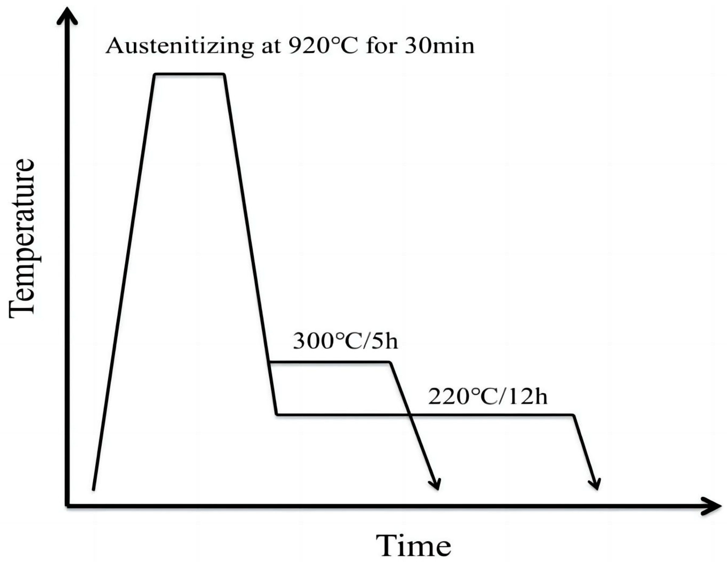
2. Experimental Materials and Procedures

Table 1 displays the chemical composition of the bainitic steel that was utilized in this investigation. Based on previous studies [34], it is known that the Ms of the experimental steel is 190 ± 5 °C and 0.05 °C/s is the critical cooling rate for martensitic transformation. In this work, two specimens isothermally heat-treated at various temperatures were prepared, and the differential scanning calorimetry (DSC) curves of their various heating speeds were then measured using a simultaneous thermal analyzer, respectively, to assure the validity of the data and remove the chance factor. A NETZSCH DIL 402C dilatometer from NETZSCH, Selb, Germany, was then used to measure the cooling rate expansion curves for a cooling rate of 0.005 °C/s and the JMatPro V13.0 [35] simulated precipitate generation versus temperature. The kinetic equations of the precipitates were obtained using Kissinger’s and JMAK’s equations and the DSC data.
The specimens were processed using a NETZSCH DIL 402C dilatometer. The samples were heated to a temperature of 920 °C and then held for 30 min for austempering. Subsequently, they were cooled temperatures of 300 °C and 220 °C at a rate of 20 °C/min for austempering heat treatment, and held for 5 h and 12 h respectively. Finally, after the completion of the austempering heat treatment, they were cooled to room temperature. The schematic diagram of the austempering heat treatment process is shown in Figure 1.
The microhardness of the material was measured after austempering treatment at 300 °C/5 h and 220 °C/12 h with a load of 1 kg and a holding time of 10 s. Ten points were randomly selected for microhardness measurements for each specimen, and a certain distance was maintained between the 10 points to ensure that they would not affect each other.
Afterwards, the microstructure of the specimens was observed using a scanning electron microscope (SEM), model SUPRA-4, Carl Zeiss, Jena, Germany, and a transmission electron microscope (TEM), model FEI Talos F200, manufactured by FEI Company, Hillsboro, OR, USA. And for TEM experiments, 3 mm-diameter flakes were ground to ~30 μm thickness and then electropolished to perforation on a dual jet device at 27 V, and the perforated foils were observed by transmission electron microscopy at an operating voltage of 200 kV. After obtaining the TEM images of the microstructure, the Powder Diffraction Files (PDF) published by the International Centre for Diffraction Data were used for the phase identification of the microstructure in the specimens. Additionally, Image-Pro Plus 6.0 software was utilized to quantify the morphological distribution of each phase within the microstructure.
Based on the kinetic equation calculations for the specimens’ precipitates, it was determined that the generation of each phase reached a maximum after 4000 s at 600 °C. Consequently, the two specimens were tempered at this temperature for 4000 s. The microhardness of the tempered samples was tested using the same measurement method as previously employed. The volume fraction of residual austenite is measured using mechanically polished specimens with an X-ray diffractometer (X-350A) manufactured by Handan Aoste Stress Technology Co., Ltd., Handan, China. Subsequently, at least ten microphotographs of the microstructure were taken before and after tempering. The morphology and distribution ratio of each phase were quantitatively analyzed using Image Pro Plus 6.0 software.

3. Results and Discussion

3.1. Kinetic Equation of M/A Decomposition

The derived kinetic equation describes the overall tempering process, encompassing not only the decomposition of M/A but also the transformation of retained austenite (RA) and the bainite matrix during tempering [21]. Nevertheless, this kinetic equation still describes well the M/A decomposition [27,36]. The kinetic equations for the austempering phase transition can be described using the JMAK equation as follows:
f = 1 exp k t n
k = k 0   e x p   ( E R T )
where f is the fraction of new phase generation; k is the reaction rate constant; k 0 is the pre-exponential factor, a constant determined by the material and type of phase transition; t is the phase transition time; n is the Avrami exponent; R is the gas constant (8.314 J / ( m o l · k ) ); T is the thermodynamic temperature; and E is the phase transition activation energy.
Taking the logarithm twice on both sides of Equation (1) results in:
ln ln ( 1 1 f ) = n ln k + n ln t
Substituting (2) into (3) simplifies to:
ln ln ( 1 1 f ) = n E R T + n ln k 0 + n ln t
The most widely used method to test the applicability of the JMAK model in non-isothermal DSC experiments is to use the Avrami plot, a linear dependance of lnln(1 − f) as a function of 1/T. According to Equation (4), the slope of the Avrami plot can be expressed as:
d ln ln 1 1 f d 1 T n E R
Let A = e x p [ ( k t ) n ] , where A is the fraction untransformed. Thus, the rate of change in the untransformed fraction, A, is:
d A d t = k f
Substitute (2) into (6) to obtain:
d A d t = k 0 f e x p [ E R T ]
A derivation of t on both sides is obtained:
d d A d t d t = k 0 e x p [ E R T ] d f d t + k 0 f d [ e x p ( E R T ) ] d t
Let d T d t = C (C is the rate of temperature rise), so d [ e x p ( E R T ) ] d t = E C R T 2 e x p [ E R T ] .
When T = T p , d d A d t d t = 0 (Tp is the peak temperature), substituting into (8) gives:
0 = d f d t + f E C R T p 2
Since d f d t = d f d A d A d t = d f d A k 0 f e x p [ E R T ] , substituting in (9) gives:
0 = k 0 exp [ E R T p ] d f d A + E C R T p 2
Using (10), taking logarithms on both sides gives:
ln [ C T p 2 ] = ln [ k 0 R E ] + ln [ d f d A ] E R T p
Since f = 1 exp k t n = 1 A , so df dA = 1 , so ln [ d f d A ] = 0 . So (11) is simplified to:
ln [ C T p 2 ] = E R T p + ln k 0 R E
The above equation is known as the Kissinger formula [37].
The slope and intercept of line (12) can be used to find E and k0, and by substituting the value of E into Equation (5), n can be calculated.
The DSC curves of the 300 °C/5 h specimens with different heating speeds are shown in Figure 2, from which the temperatures corresponding to the exothermic peaks at different heating speeds, Tp, can be obtained. In Figure 2, both the temperature and area of the exothermic peak in the DSC curve increase with the increase in heating rate. The range of the exothermic peak is between 450 and 600 °C, and under a cooling rate of 0.005 °C/s, the expansion curve fluctuates slightly between 560 °C and 770 °C (Figure 2a). By simulating the test steel with JMatPro V13.0 software, the generation temperatures of various precipitates are shown in Figure 3b, and various precipitates begin to form around 600 °C. The exothermic peaks in the DSC curves and the fluctuations on dilatation curves, are attributed to the decomposition of M/A and RA at around 600 °C [38]. In the Kissinger formula, l n C T p 2 is used as the linear function of 1 T p , and the DSC data of the sample treated at 300 °C are fitted, as shown in Figure 4a. The relationship between the amount of precipitate f and the temperature T is obtained by processing the exothermic peaks, and the slope (Figure 5) is obtained by fitting a straight line with ln ln ( 1 1 f ) as a function of 1 T . By inserting the attained value of E into the slope value (Equation (4)), one can derive the respective n values at varying heating rates. The kinetic parameters of the specimens were calculated and are statistically presented in Table 2. The kinetic equation for the 220 °C/12 h specimen is calculated in the same way as for the 300 °C/5 h specimen. Unlike the specimen that underwent austempering heat treatment at 300 °C, the specimen treated at 220 °C/12 h exhibited an additional exothermic peak between 280 °C and 350 °C (Figure 6). The 220 °C/12 h specimen had 13.4% residual austenite, and the tested steel’s bainite transformation temperature was approximately 300 °C [39,40]. Therefore, the exothermic peak at 300 °C may be due to the exothermic phenomenon caused by the transformation of residual austenite into bainite [41].
Each parameter of the kinetic equation was derived from the DSC data (Table 2), and by substituting these parameters into Equations (1) and (2), the kinetic equations for the precipitates of the two specimens listed in Table 3 were obtained.

3.2. Experimental Validation of the Proposed Kinetic Equation and Decomposition of M/A

Volume fraction transformed versus time can be determined using the kinetic equations displayed in Table 3, derived using parameters from Table 2. Since the two samples’ exothermic peaks all lie close to 600 °C, this temperature was chosen as the specimens’ tempering condition. Figure 7 shows the calculated relative volume fraction of precipitates with time at 600 °C. The figure reveals that the generation of each phase peaks after 4000 s at 600 °C. So according to the calculation, the two specimens were tempered at 600 °C for 4000 s.

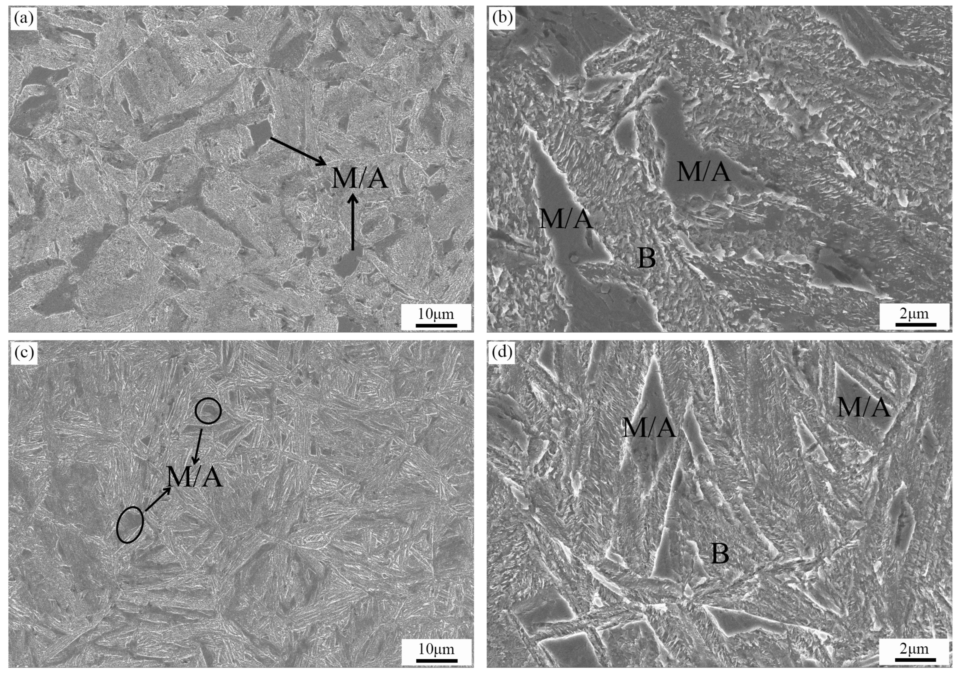
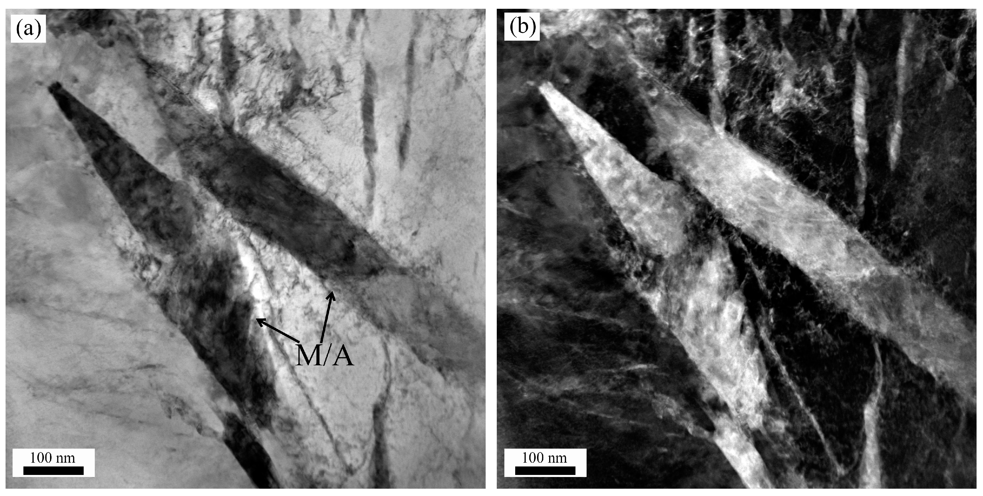
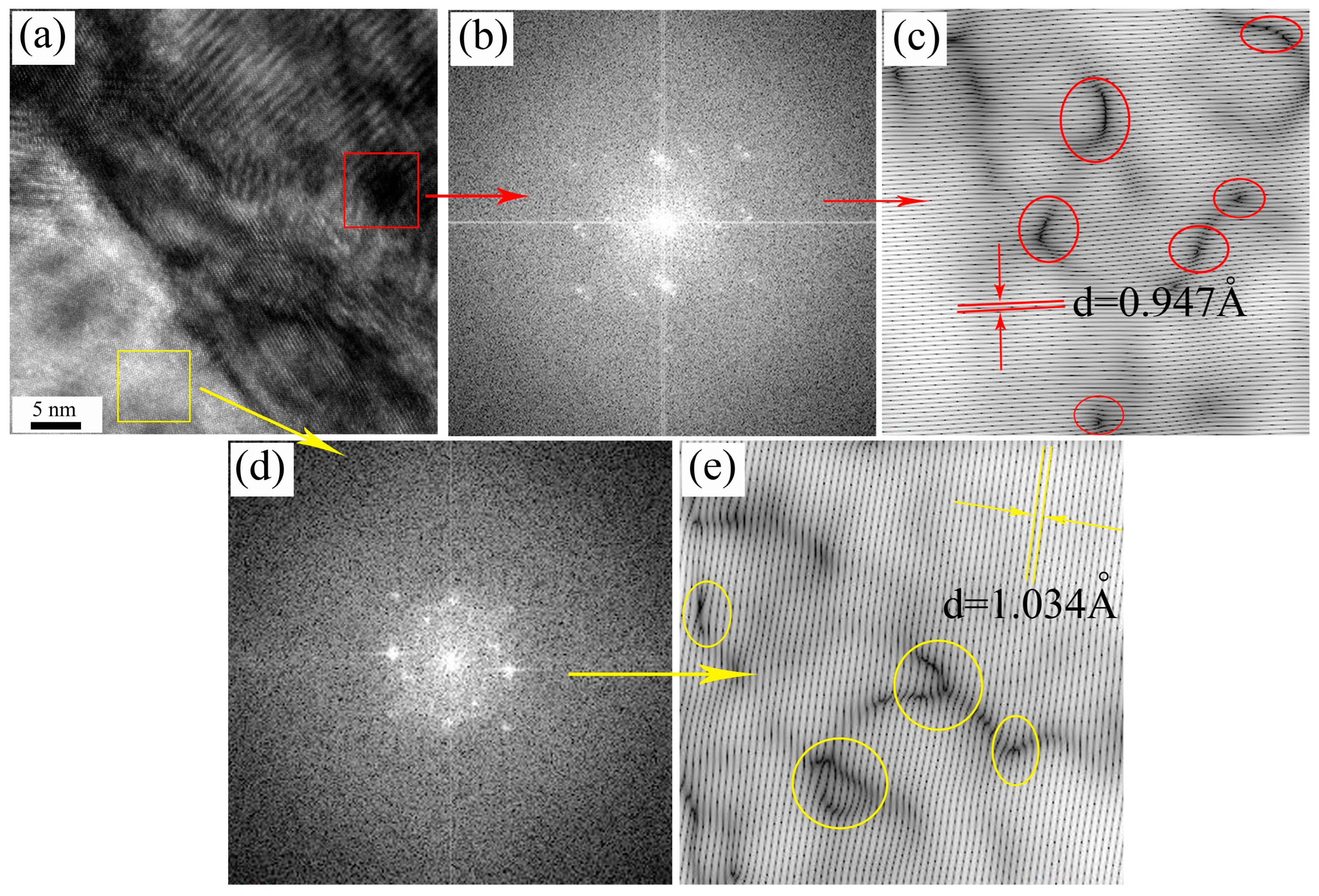
3.2.1. Analysis of the Microstructure Prior to Tempering

Numerous lumpy, up-convex M/A microstructures were observed at the low magnification microphotographs (Figure 8a,c) [42]. These microstructures were further examined using a transmission electron microscope to observe the 220 °C austempering heat-treated microstructure, as illustrated in Figure 9, which displays the bright-field and dark-field microphotographs of the M/A microstructure. The high-resolution picture of the block microstructure near the edge in Figure 10a makes it clear that there are two distinct microstructures. As seen in Figure 10c,e, the lattice fringes can be obtained by applying the Fourier and inverse Fourier transforms. It is possible to calculate the crystal plane spacing between the block microstructure edge and core microstructure. Through a comparison of the Powder Diffraction Files (PDF) cards’ crystallographic spacing [43], it can be determined that the red rectangular box’s core microstructure is a martensitic microstructure (103) crystal face (PDF card: 44-1293), while the yellow rectangular box’s edge microstructure is an austenitic microstructure (222) crystal face (PDF card: 33-0397). Accordingly, the lumpy microstructure that is up-convex has an austenitic exterior and a martensitic core, which is typical of M/A [43].
During the isothermal transformation of bainite, the transformation generally halts prematurely after a certain amount of bainite has formed, before reaching equilibrium [44,45]. This phenomenon, known as the incomplete transformation phenomenon (ICT) [46], results in a portion of untransformed austenite remaining at the end of the bainite transformation. This untransformed austenite is morphologically classified as thin films and lumps [47]. After the austempering heat treatment is finished, the thin film of austenite is typically more stable of the two forms and does not go through any additional phase changes when cooling to room temperature [48]. Thin-film austenite adds to the material’s toughness, and this austenite stabilization permits the austenite structure to be preserved at room temperature. In contrast, block austenite will experience a martensitic phase transformation in the core due to the difference in elemental content between the core and surface layers, while the surface layer will maintain its austenitic microstructure when the material cools to room temperature following the austempering heat treatment [49,50].

3.2.2. Impact of Tempering on the Microstructure

The SEM images of the samples after five hours of post-tempering at 600 °C are shown in Figure 11. The microstructure in the circle in Figure 11a shows the change in the morphology of the M/A microstructure after tempering, and it was found that a large amount of M/A decomposed. Furthermore, Figure 11b shows that the M/A microstructure has transformed by more than 50%; the red circle clearly shows how the blocky M/A has been decomposing gradually. The 220 °C/12 h sample and the 300 °C/5 h sample exhibit the same behavior. A significant amount of cementite will precipitate during the process of tempering, as the martensite in the M/A decomposes in accordance with the martensitic tempering transformation mechanism [51]. Because of the high tempering temperature, the slower residual austenite decomposition also breaks down smoothly into a mixture of ferrite and cementite [52]. A review of Figure 11a,c reveals that most of the bulk M/A has decomposed. In Figure 11d, it is observed that the precipitated carbide grows as a one-dimensional nucleus in the form of a long rod. This observation also correlates with an Avrami exponent n, which is found to be about 1 [53]. Statistical data on the tempered M/A structure (at least 10 pictures of the same magnification in each group), presented in Figure 12, reveal that post-tempering, the decomposition content of the M/A structure has dropped below 1%, a result consistent with the kinetic equation’s calculations. Residual austenite measurements on the tempered specimens were performed using an X-ray diffractometer, which revealed that the content of residual austenite in the microstructure had decreased from approximately 10% to nearly zero. This implies that a considerable amount of residual austenite decomposition occurred in addition to the bulk M/A decomposition that occurred during the tempering process.
Figure 13 shows the variations in the specimens’ hardness levels before and after tempering. However, after tempering the specimens for 4000 s at 600 °C, the average hardness values decreased from 510 and 625 HV to 445 and 461 HV, respectively, due to the decomposition of the M/A [51,54].

4. Conclusions

In this study, the kinetic equations for the decomposition of M/A structures were analytically computed using Kissinger’s method and the JMAK approach. Subsequently, the outcomes of these kinetic equations were employed to validate the accuracy of the equations and facilitate the decomposition of the unwanted M/A structures. The ensuing conclusions are as follows:
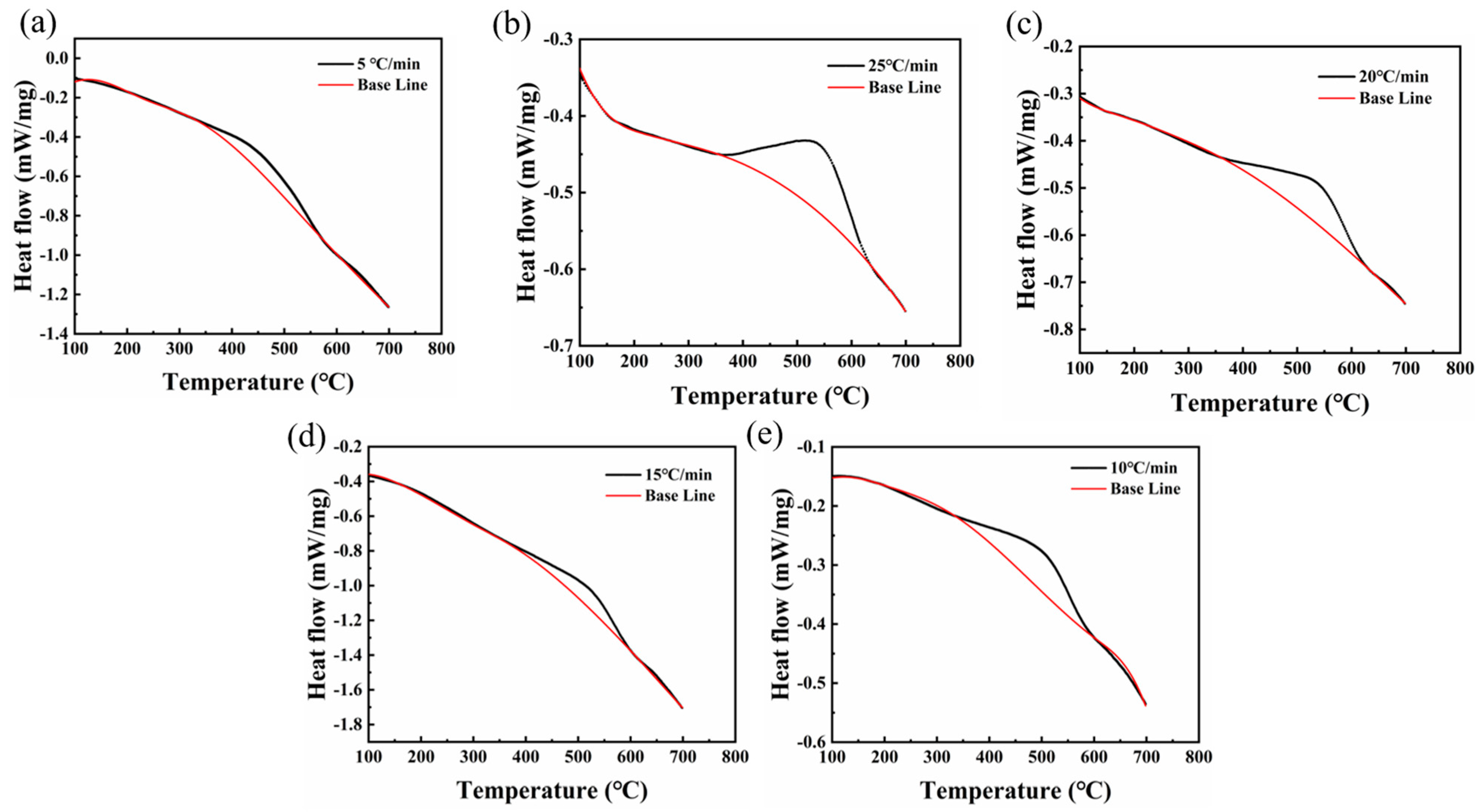
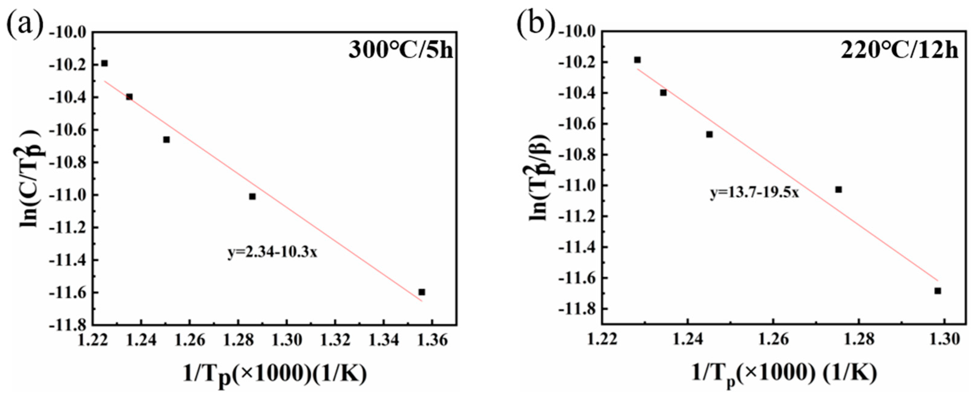
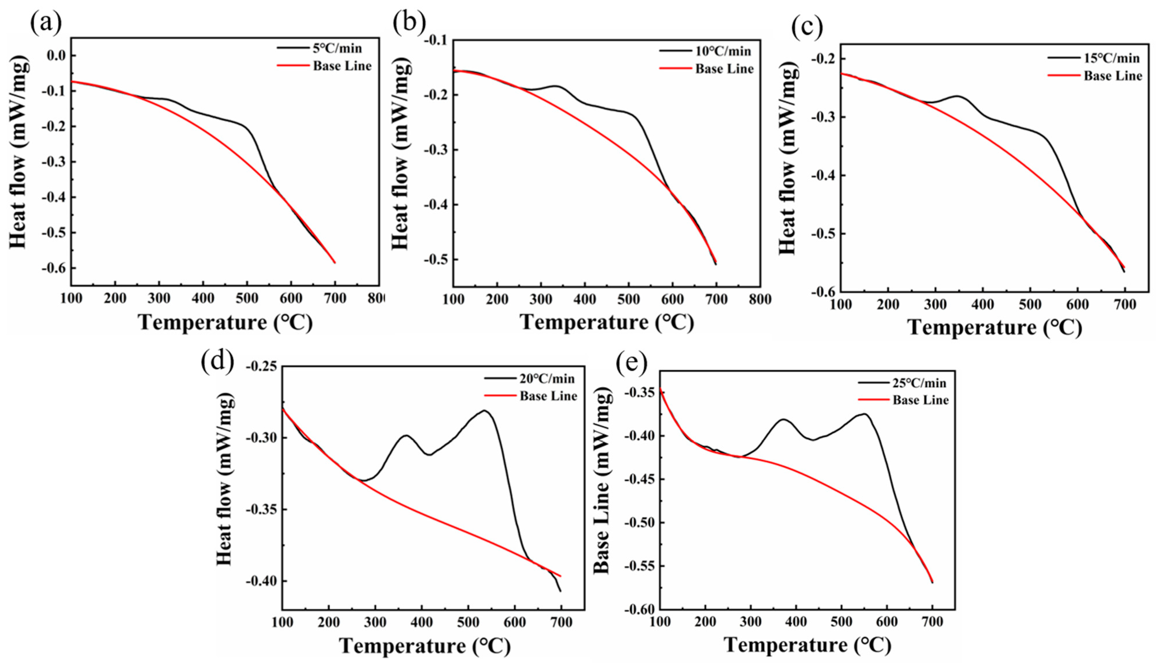
  • Each sample demonstrated exothermic peaks proximate to 600 °C at varying heating rates. Notably, the 220 °C/12 h sample exhibited two such peaks, one near 300 °C and another around 600 °C. The precipitation activation energies for these exothermic peaks at 600 °C in the 300 °C/5 h and 220 °C/12 h samples were 85.8 kJ/mol and 161.12 kJ/mol, respectively.
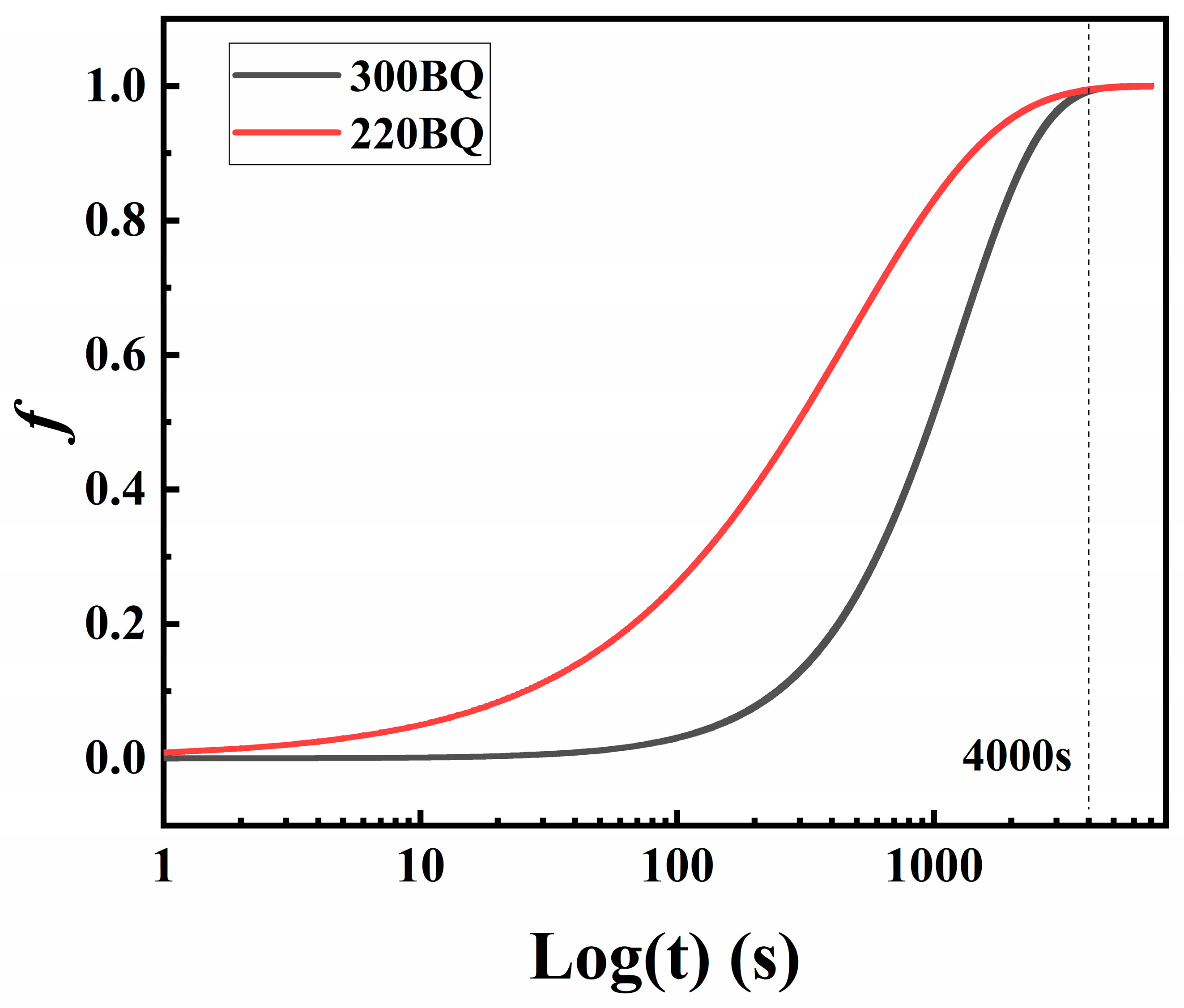
  • The kinetic equation was derived from the DSC data, and its computation indicated that the carbide precipitation completion time was approximately 67 min at 600 °C.
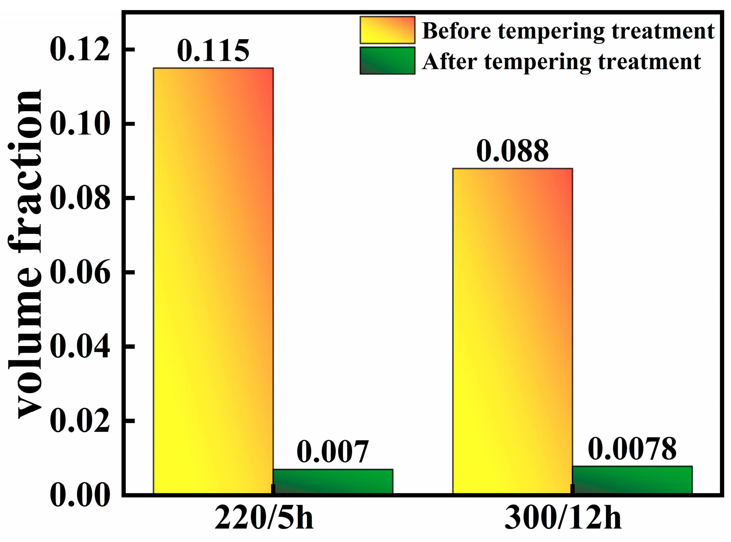
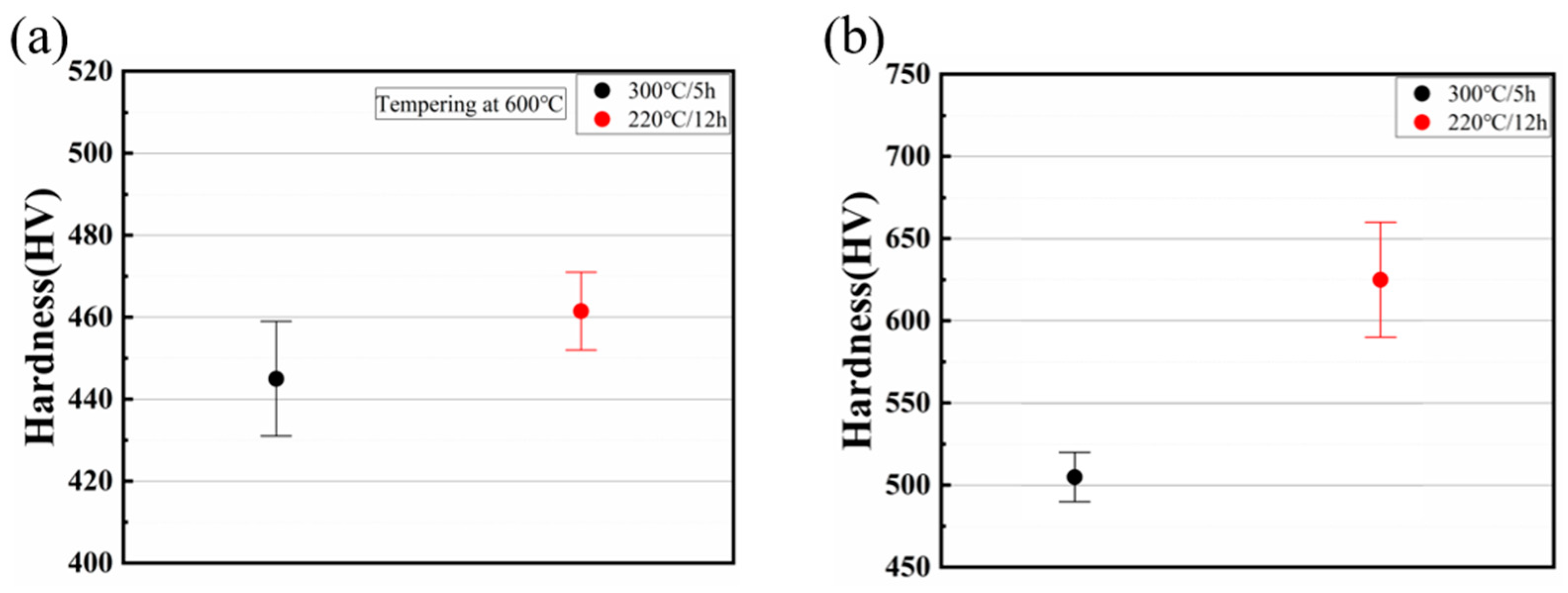
  • To confirm this outcome, the specimen underwent a tempering process at 600 °C for a duration of 67 min. A subsequent microscopic examination revealed a significant decomposition of the M/A structure, indicating a residual volume fraction at less than 1%. Additionally, the sample’s hardness decreased to approximately 450 HV, a consequence of the M/A decomposition post-tempering.

Author Contributions

Z.Q.: Methodology, Validation, Formal analysis, Investigation, Data curation, Writing—original draft, Writing—review and editing. M.L.: Validation, Formal analysis, Writing—original draft. G.C.: Conceptualization, Methodology, Writing—review and editing. C.H.: Resources, Writing—original draft. D.L.: Writing—original draft. A.L.: Writing—original draft. All authors have read and agreed to the published version of the manuscript.

Funding

This research received no external funding.

Institutional Review Board Statement

Not applicable.

Informed Consent Statement

Not applicable.

Data Availability Statement

Data are contained within the article.

Conflicts of Interest

The authors declare no conflict of interest.

References

  1. Tian, J.; Xu, G.; Jiang, Z.; Hu, H.; Zhou, M. Effect of Ni Addition on Bainite Transformation and Properties in a 2000 MPa Grade Ultrahigh Strength Bainitic Steel. Met. Mater. Int. 2018, 24, 1202. [Google Scholar] [CrossRef]
  2. Hu, H.; Tian, J.; Xu, G.; Zurob, H.S. New insights into the effects of deformation below-MS on isothermal kinetics of bainitic transformation. J. Mater. Res. Technol. 2020, 9, 15750. [Google Scholar] [CrossRef]
  3. Shi, R.; Wang, Y.; Lu, S.; Liu, S.; Tu, Y.; Yang, S.; Gao, K.; Yang, X.; Pang, X. Enhancing the hydrogen embrittlement resistance with cementite/VC multiple precipitates in high-strength steel. Mater. Sci. Eng. A 2023, 874, 145084. [Google Scholar] [CrossRef]
  4. Zhang, W.; Shang, X.; Chen, S.; Zhang, L. Comparison of microstructural characteristics and mechanical properties of the high-strength low-alloy steels fabricated by wire arc additive manufacturing versus conventional casting. Mater. Sci. Eng. A 2023, 885, 145593. [Google Scholar] [CrossRef]
  5. Wang, S.; Gao, Z.; Wu, G.; Mao, X. Titanium microalloying of steel: A review of its effects on processing, microstructure and mechanical properties. Int. J. Miner. Metall. Mater. 2022, 29, 645. [Google Scholar] [CrossRef]
  6. Li, K.; Yang, T.; Gong, N.; Wu, J.; Wu, X.; Zhang, D.Z.; Murr, L.E. Additive manufacturing of ultra-high strength steels: A review. J. Alloy Compd. 2023, 965, 171390. [Google Scholar] [CrossRef]
  7. Avishan, B.; Sefidgar, A.; Yazdani, S. High strain rate deformation of nanostructured super bainite. J. Mater. Sci. 2019, 54, 3455. [Google Scholar] [CrossRef]
  8. Golchin, S.; Avishan, B.; Yazdani, S. Effect of 10% ausforming on impact toughness of nano bainite austempered at 300 °C. Mater. Sci. Eng. A 2016, 656, 94. [Google Scholar] [CrossRef]
  9. Li, Q.; Zhang, Y.; Li, W.; Huang, X.; Huang, W. Improved Mechanical Properties of a Quenched and Partitioned Medium-Carbon Bainitic Steel by Control of Bainitic Isothermal Transformation. J. Mater. Eng. Perform. 2020, 29, 32. [Google Scholar] [CrossRef]
  10. Pashangeh, S.; Karimi Zarchi, H.R.; Ghasemi Banadkouki, S.S.; Somani, M.C. Detection and Estimation of Retained Austenite in a High Strength Si-Bearing Bainite-Martensite-Retained Austenite Micro-Composite Steel after Quenching and Bainitic Holding (Q&B). Metals 2019, 9, 492. [Google Scholar] [CrossRef]
  11. Pashangeh, S.; Somani, M.C.; Ghasemi Banadkouki, S.S.; Karimi Zarchi, H.R.; Kaikkonen, P.; Porter, D.A. On the decomposition of austenite in a high-silicon medium-carbon steel during quenching and isothermal holding above and below the Ms temperature. Mater. Charact. 2020, 162, 110224. [Google Scholar] [CrossRef]
  12. Mola, J.; Seo, E.J.; Cho, L. Correlation between mechanical stability and hardness of austenite in martensite/austenite mixtures. Mater. Sci. Eng. A 2021, 822, 141687. [Google Scholar] [CrossRef]
  13. Li, X.; Fan, Y.; Ma, X.; Subramanian, S.V.; Shang, C. Influence of Martensite–Austenite constituents formed at different intercritical temperatures on toughness. Mater. Des. 2015, 67, 457. [Google Scholar] [CrossRef]
  14. Varshney, A.; Sangal, S.; Pramanick, A.K.; Mondal, K. On the extent of transformation of austenite to bainitic ferrite and carbide during austempering of high Si steel for prolonged duration and its effect on mechanical properties. Mater. Sci. Eng. A 2020, 793, 139764. [Google Scholar] [CrossRef]
  15. Caballero, F.G.; Garcia-Mateo, C.; Miller, M.K. Design of Novel Bainitic Steels: Moving from UltraFine to Nanoscale Structures. JOM 2014, 66, 747. [Google Scholar] [CrossRef]
  16. Su, R.; Chen, J.; Chen, H.; Zhang, Z.; Zhao, X.; Lei, Z.; Wang, D.; Meng, Y.; Zhang, Z. Low-temperature impact toughness of laser–arc hybrid welded low-carbon bainitic steel. J. Mater. Sci. 2023, 58, 12775. [Google Scholar] [CrossRef]
  17. Zhao, L.; Qian, L.; Meng, J.; Zhou, Q.; Zhang, F. Below-Ms austempering to obtain refined bainitic structure and enhanced mechanical properties in low-C high-Si/Al steels. Scr. Mater. 2016, 112, 96. [Google Scholar] [CrossRef]
  18. Feng, J.; Frankenbach, T.; Wettlaufer, M. Strengthening 42CrMo4 steel by isothermal transformation below martensite start temperature. Mater. Sci. Eng. A 2017, 683, 110. [Google Scholar] [CrossRef]
  19. Xia, S.; Zhang, F.; Yang, Z. Microstructure and mechanical properties of 18Mn3Si2CrMo steel subjected to austempering at different temperatures below Ms. Mater. Sci. Eng. A 2018, 724, 103. [Google Scholar] [CrossRef]
  20. Huda, N.; Ding, Y.; Gerlich, A.P. Temper-treatment development to decompose detrimental martensite-austenite and its effect on linepipe welds. Mater. Sci. Tech. 2017, 33, 1978. [Google Scholar] [CrossRef]
  21. Santajuana, M.A.; Rementeria, R.; Kuntz, M.; Jimenez, J.A.; Caballero, F.G.; Garcia-Mateo, C. Low-Temperature Bainite: A Thermal Stability Study. Metall. Mater. Trans. A 2018, 49, 2026. [Google Scholar] [CrossRef]
  22. Rafiei, M.; Mirzadeh, H.; Malekan, M. Precipitation kinetics of γ″ phase and its mechanism in a Nb-bearing nickel-based superalloy during aging. Vacuum 2020, 178, 109456. [Google Scholar] [CrossRef]
  23. Mehta, B.; Frisk, K.; Nyborg, L. Effect of precipitation kinetics on microstructure and properties of novel Al-Mn-Cr-Zr based alloys developed for powder bed fusion—Laser beam process. J. Alloy. Compd. 2022, 920, 165870. [Google Scholar] [CrossRef]
  24. Ghaemifar, S.; Mirzadeh, H. Precipitation kinetics of gamma double prime phase during direct aging treatment of inconel 718 superalloy additively manufactured by selective laser melting. J. Mater. Res. Technol. 2023, 27, 4248–4255. [Google Scholar] [CrossRef]
  25. Wang, Y.Q.; Shen, Y.F.; Jia, N.; Wang, J.J.; Xue, W.Y. Dynamic recrystallization and constitutive equation of 15Cr-10Mn-Ni-N steel under hot deformation. Mater. Today Commun. 2023, 35, 105648. [Google Scholar] [CrossRef]
  26. Yang, H.; Wang, W.; Wang, C.; Wang, J.; Zhou, J.; Tong, C.; Chen, J.; Wang, B. Effects of aging process on properties and precipitation kinetics of Cu–Cr–Zr alloy strips. Trans. Nonferrous Metal. Soc. 2023, 33, 2439. [Google Scholar] [CrossRef]
  27. Smoljan, B.; Iljkić, D.; Smokvina Hanza, S.; Hajdek, K. Mathematical Modelling of Isothermal Decomposition of Austenite in Steel. Metals 2021, 11, 1292. [Google Scholar] [CrossRef]
  28. Miao, D.; Xu, J.; Jiang, S.; Ning, X.; Liu, J.; Shang, S. Crystallization temperature investigation of Cu2ZnSnS4 by using Differential scanning calorimetry (DSC). Ceram. Int. 2018, 44, 4256. [Google Scholar]
  29. Svoboda, R.; Maqueda, L.P.; Podzemná, V.; Perejon, A.; Svoboda, O. Influence of DSC thermal lag on evaluation of crystallization kinetics. J. Non-Cryst. Solids 2020, 528, 119738. [Google Scholar] [CrossRef]
  30. Rico, J.J.; Pérez-Orozco, R.; Patiño Vilas, D.; Porteiro, J. TG/DSC and kinetic parametrization of the combustion of agricultural and forestry residues. Biomass Bioenergy 2022, 162, 106485. [Google Scholar] [CrossRef]
  31. Vyazovkin, S.; Sbirrazzuoli, N. Nonisothermal Crystallization Kinetics by DSC: Practical Overview. Processes 2023, 11, 1438. [Google Scholar] [CrossRef]
  32. Zhu, H.; Lei, Y.; Yu, P.; Li, C.; Yao, B.; Yang, S.; Lu, Y.; Peng, H. Novel high-precision wax molecular diffusion coefficient correlation based on the diffusion laboratory apparatus coupled with differential scanning calorimeter. Fuel 2024, 355, 129452. [Google Scholar] [CrossRef]
  33. Mirzajani, V.; Nazarpour-Fard, H.; Farhadi, K. Impacts of titanium dioxide nanoparticles on thermal decomposition kinetics of nitrocellulose-based propellant as a bio-derived polymer. Iran. Polym. J. 2024, 33, 699. [Google Scholar] [CrossRef]
  34. Chen, G.; Lei, M.; Wan, M.; Huang, C. Effect of pre-formed martensite quenching plus inverted multi-step heat treatment on medium-carbon alloy steel. Arch. Civ. Mech. Eng. 2023, 23, 99. [Google Scholar] [CrossRef]
  35. Sun, R.; Mi, G. Influence of Alloying Elements Content on High Temperature Properties of Ti-V-Cr and Ti-Al-V Series Titanium Alloys: A JMatPro Program Calculation Study. J. Phys. Conf. Ser. 2023, 2639, 12019. [Google Scholar] [CrossRef]
  36. Park, G.; Kim, K.; Lee, Y.; Uhm, S.; Lee, C. Kinetics Study on Low-Temperature Tempering of Martensitic Phase in Medium Mn Steel Weldment During Paint-Baking Heat Treatment. Met. Mater. Int. 2022, 28, 1157. [Google Scholar] [CrossRef]
  37. Blaine, R.L.; Kissinger, H.E. Homer Kissinger and the Kissinger equation. Thermochim. Acta 2012, 540, 1. [Google Scholar] [CrossRef]
  38. Hajra, R.N.; Dash, M.K.; Chu, W.; Singh, A.N.; Nam, K.; Kim, J.H. High-temperature phase stability, γ → δ transformation of ferritic/martensitic steel studied by differential scanning calorimetry and electron backscatter diffraction. J. Therm. Anal. Calorim. 2023, 148, 3357. [Google Scholar] [CrossRef]
  39. Guo, H.; Feng, X.; Zhao, A.; Li, Q.; Chai, M. Effects of ausforming temperature on bainite transformation kinetics, microstructures and mechanical properties in ultra-fine bainitic steel. J. Mater. Res. Technol. 2020, 9, 1593. [Google Scholar] [CrossRef]
  40. Kawata, H.; Manabe, T.; Fujiwara, K.; Takahashi, M. Effect of Carbon Content on Bainite Transformation Start Temperature in Middle–High Carbon Fe–9Ni–C Alloys. ISIJ Int. 2018, 58, 165. [Google Scholar] [CrossRef]
  41. Baricco, M.; Franzosi, G.; Nada, R.; Battezzati, L. Thermal effects due to tempering of austenite and martensite in austempered ductile irons. Mater. Sci. Tech. 1999, 15, 643. [Google Scholar] [CrossRef]
  42. Zhao, J.; Zhao, X.; Zhao, X.; Dong, C.; Kang, S. Effects of nucleation site and morphology of carbide-free bainite on microstructures and properties of bainite/martensite multi-phase steels. Mater. Sci. Eng. A 2019, 744, 86. [Google Scholar] [CrossRef]
  43. Gindhart, A.; Blanton, T.; Blanton, J.; Gates-Rector, S. The Power of Electron Diffraction Phase Analysis and Pattern Simulations Using the ICDD ® Powder Diffraction File™ (PDF-4+). Microsc. Microanal. 2016, 22, 1440. [Google Scholar] [CrossRef]
  44. Wu, H.D.; Miyamoto, G.; Yang, Z.G.; Zhang, C.; Chen, H.; Furuhara, T. Incomplete bainite transformation in Fe-Si-C alloys. Acta Mater. 2017, 133, 1. [Google Scholar] [CrossRef]
  45. Xia, Y.; Miyamoto, G.; Yang, Z.G.; Zhang, C.; Furuhara, T. Direct measurement of carbon enrichment in the incomplete bainite transformation in Mo added low carbon steels. Acta Mater. 2015, 91, 10. [Google Scholar] [CrossRef]
  46. Aaronson, H.I.; Reynolds, W.T.; Purdy, G.R. The incomplete transformation phenomenon in steel. Metall. Mater. Trans. A 2006, 37, 1731. [Google Scholar] [CrossRef]
  47. Gao, G.; Zhang, B.; Cheng, C.; Zhao, P.; Zhang, H.; Bai, B. Very high cycle fatigue behaviors of bainite/martensite multiphase steel treated by quenching-partitioning-tempering process. Int. J. Fatigue 2016, 92, 203. [Google Scholar] [CrossRef]
  48. Chandiran, E.; Ueji, R.; Ogawa, Y.; Nagata, K.; Somekawa, H.; Demura, M. Deformation behaviour of novel medium carbon bainitic steels with different retained austenite characteristics designed by the sparse mixed regression model. J. Mater. Res. Technol. 2022, 19, 2179. [Google Scholar] [CrossRef]
  49. Hofer, C.; Bliznuk, V.; Verdiere, A.; Petrov, R.; Winkelhofer, F.; Clemens, H.; Primig, S. High-resolution characterization of the martensite-austenite constituent in a carbide-free bainitic steel. Mater. Charact. 2018, 144, 182. [Google Scholar] [CrossRef]
  50. Ackermann, M.; Resiak, B.; Buessler, P.; Michaut, B.; Bleck, W. Effect of Molybdenum and Cooling Regime on Microstructural Heterogeneity in Bainitic Steel Wires. Steel Res. Int. 2020, 91, 1900663. [Google Scholar] [CrossRef]
  51. Yen, H.; Chiang, M.; Lin, Y.; Chen, D.; Huang, C.; Lin, H. High-Temperature Tempered Martensite Embrittlement in Quenched-and-Tempered Offshore Steels. Metals 2017, 7, 253. [Google Scholar] [CrossRef]
  52. Ruiz-Jimenez, V.; Kuntz, M.; Sourmail, T.; Caballero, F.G.; Jimenez, J.A.; Garcia-Mateo, C. Retained Austenite Destabilization during Tempering of Low-Temperature Bainite. Appl. Sci. 2020, 10, 8901. [Google Scholar] [CrossRef]
  53. Manchón-Gordón, A.F.; Blázquez, J.S.; Conde, C.F.; Conde, A. Nanocrystallization kinetics understood as multiple microprocesses following the classical theory of crystallization. J. Alloy. Compd. 2016, 675, 81. [Google Scholar] [CrossRef]
  54. Rogal, A.; Dutkiewicz, J. Effect of annealing on microstructure, phase composition and mechanical properties of thixo-cast 100Cr6 steel. Mater. Charact. 2012, 68, 123. [Google Scholar] [CrossRef]
Figure 1. Schematic diagram of heat treatment process flow.
Materials 17 02690 g001
Figure 2. DSC curves of 300 °C austempering heat treatment samples at different heating rates (ae).
Materials 17 02690 g002
Figure 3. (a) Dilation temperature curve with cooling rate of 0.005 °C/s; (b) relationship between precipitation and temperature simulated by JMatPro V13.0.
Materials 17 02690 g003
Figure 4. Kissinger curve fitting for two heat-treated specimens: (a) 300 °C/5 h; (b) 220 °C/12 h.
Materials 17 02690 g004
Figure 5. The DSC exothermic peak of the 300 °C austempering heat treatment sample is fitted by using lnln(1/(1 − f)) for different heating rates (ae).,where the black line is the original curve of the function and the red dashed line is the fitted straight line.
Materials 17 02690 g005
Figure 6. DSC curves of 220 °C austempering heat treatment samples at different heating rates (ae).
Materials 17 02690 g006
Figure 7. Relative volume fraction of M/A constituent decomposition with time at 600 °C.
Materials 17 02690 g007
Figure 8. Microstructure after austempering heat treatment: (a,b) are austempering bainite transformation samples at 300 °C, and (c,d) are austempering bainite transformation samples at 220 °C; B: bainite structure; M/A: martensite/austenite structure.
Materials 17 02690 g008
Figure 9. TEM picture of the austenite/martensite structure following an austempering heat treatment at 220 °C., where (a) represents the M/A bright-field image and (b) represents the M/A dark-field image.
Materials 17 02690 g009
Figure 10. High-resolution images of 220 °C austempering heat treatment sample; (a) high-resolution resolution map; (b) Fourier transform of the red rectangle; (c) inverse Fourier transform of (b); (d) Fourier transform of the yellow rectangle; (e) inverse Fourier transform of (d).
Materials 17 02690 g010
Figure 11. Different austempering transformation heat-treated samples that were tempered at 600 °C for 67 min are shown in SEM images. (a,b) 300 °C/5 h; (c,d) 220 °C/12 h. Where the red circle shows the M/A decomposition after tempering, with local magnification in the direction of the arrow in (a).
Materials 17 02690 g011
Figure 12. Comparison of M/A content before and after tempering.
Materials 17 02690 g012
Figure 13. (a) Distribution of hardness values of untempered specimens; (b) the hardness distribution of the sample after tempering at 600 °C for 67 min.
Materials 17 02690 g013
Table 1. Chemical composition of experimental steel (wt.%).
ElementCSiMnCrNiMoVCuFe
wt.%0.550.3790.751.3792.6760.5160.1030.185Bal.
Table 2. Kinetic parameters of phase transformation. n ¯ is the average of n values.
E
(KJ/mol)
k0n n ¯
5
°C/min
10
°C/min
15
°C/min
20
°C/min
25
°C/min
30085.81.07 × 1021.261.311.471.421.391.37
220162.121.7 × 1070.740.760.760.770.810.77
Table 3. Dynamic equation expression.
300 f = 1 e x p ( 6.02 × 10 2 · t 1.37 · e x p ( 14138.32 T ) )
220 f = 1 e x p ( 3.69 × 10 5 · t 0.77 · e x p ( 15335.67 T ) )
Disclaimer/Publisher’s Note: The statements, opinions and data contained in all publications are solely those of the individual author(s) and contributor(s) and not of MDPI and/or the editor(s). MDPI and/or the editor(s) disclaim responsibility for any injury to people or property resulting from any ideas, methods, instructions or products referred to in the content.

