
Experimental Study on Durability and Bond Properties of GFRP Resin Bolts


Abstract
1. Introduction
2. Corrosion Testing
2.1. Preparation of the Corrosive Solution
2.2. Materials and Methods
2.3. Results and Discussion
3. Pullout Test
3.1. Test Design
3.2. Materials and Methods
3.3. Experiment Results and Analysis
4. Conclusions
- (1)
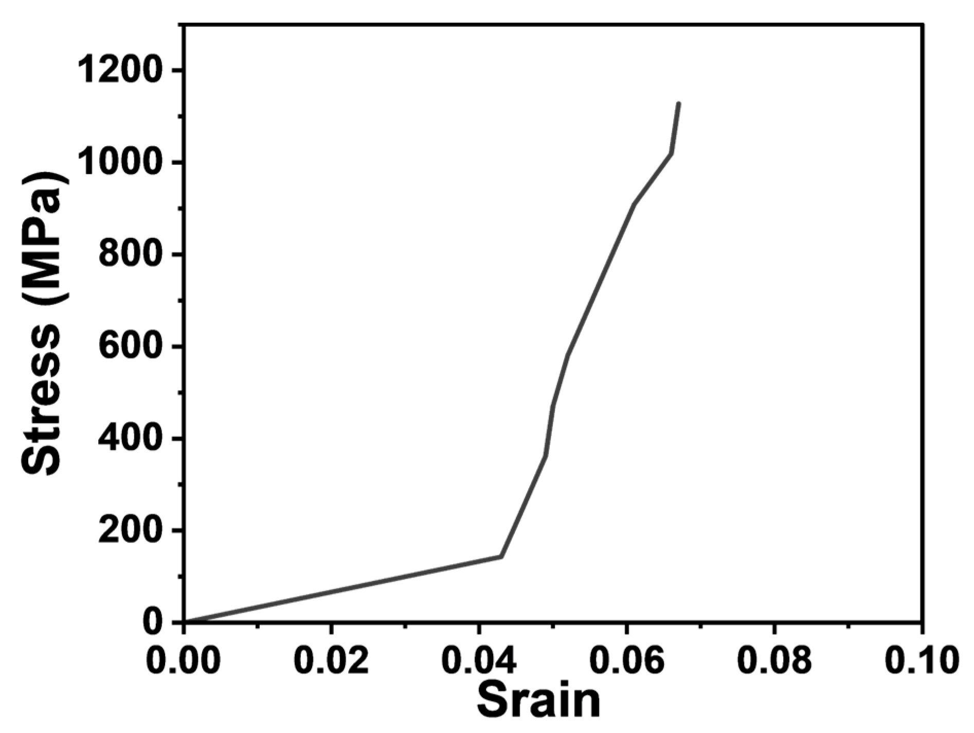
- The GFRP rods and epoxy resin exhibited excellent corrosion resistance. The strength variations of the GFRP rods and epoxy resin materials in artificial seawater environments were less than 5%. Therefore, the GFRP resin bolts were suitable for coastal protection engineering. The stress–strain relationship of GFRP tendon is approximately linear with no yield point, and its failure form is a brittle failure. It is recommended to take 75% of the ultimate tensile strength as the design value. Compared with carbon steel, GFRP has the advantages of an outstanding high strength/stiffness-to-weight ratio, ease of transportation, cutting, and installation. However, its modulus of elasticity is relatively low and should be a concern in practical engineering design.
- (2)
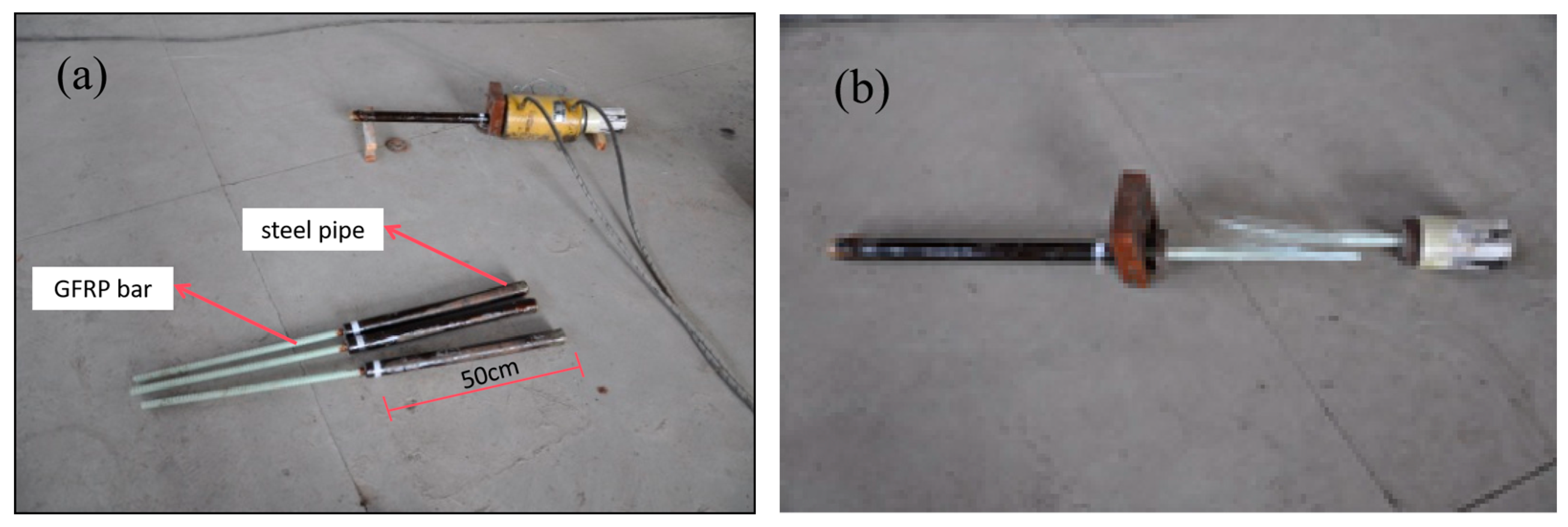
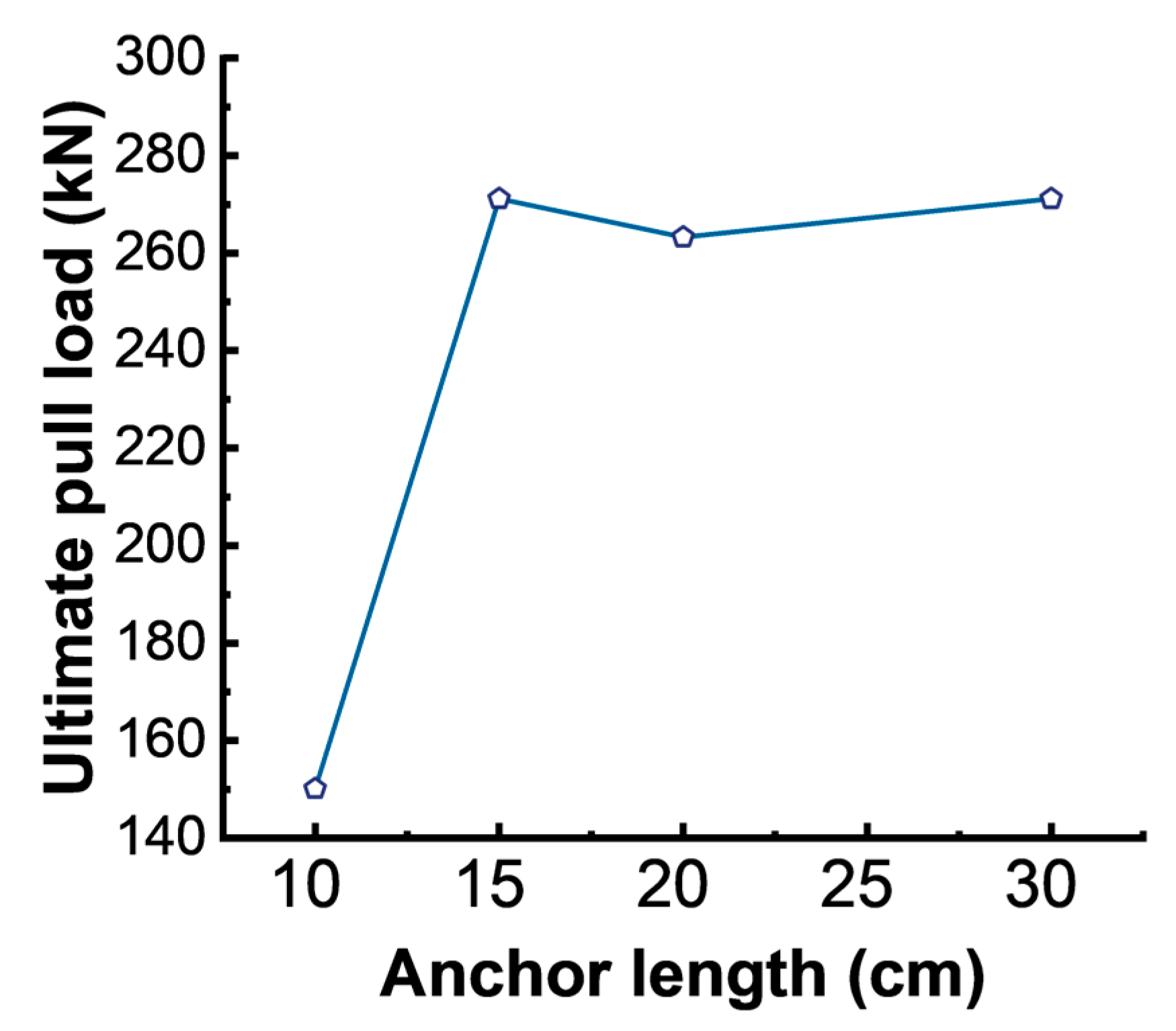
- Laboratory test results show that, when the bolt diameter and resin strength were constant, the pull load on the GFRP bolts embedded in the steel pipe along the anchoring length gradually increased and then stabilized with the increase in the anchorage length. A critical value was observed for the anchorage length of the GFRP bolts.
- (3)
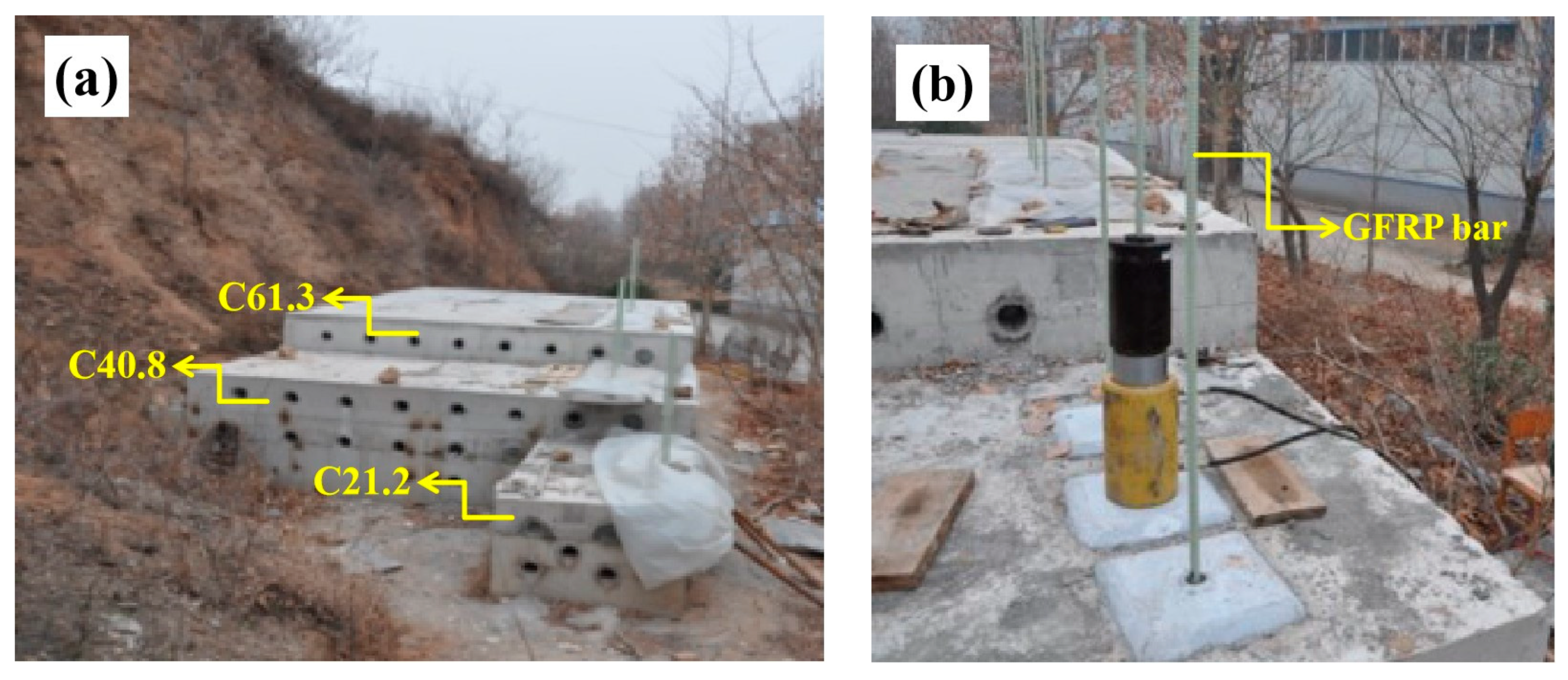
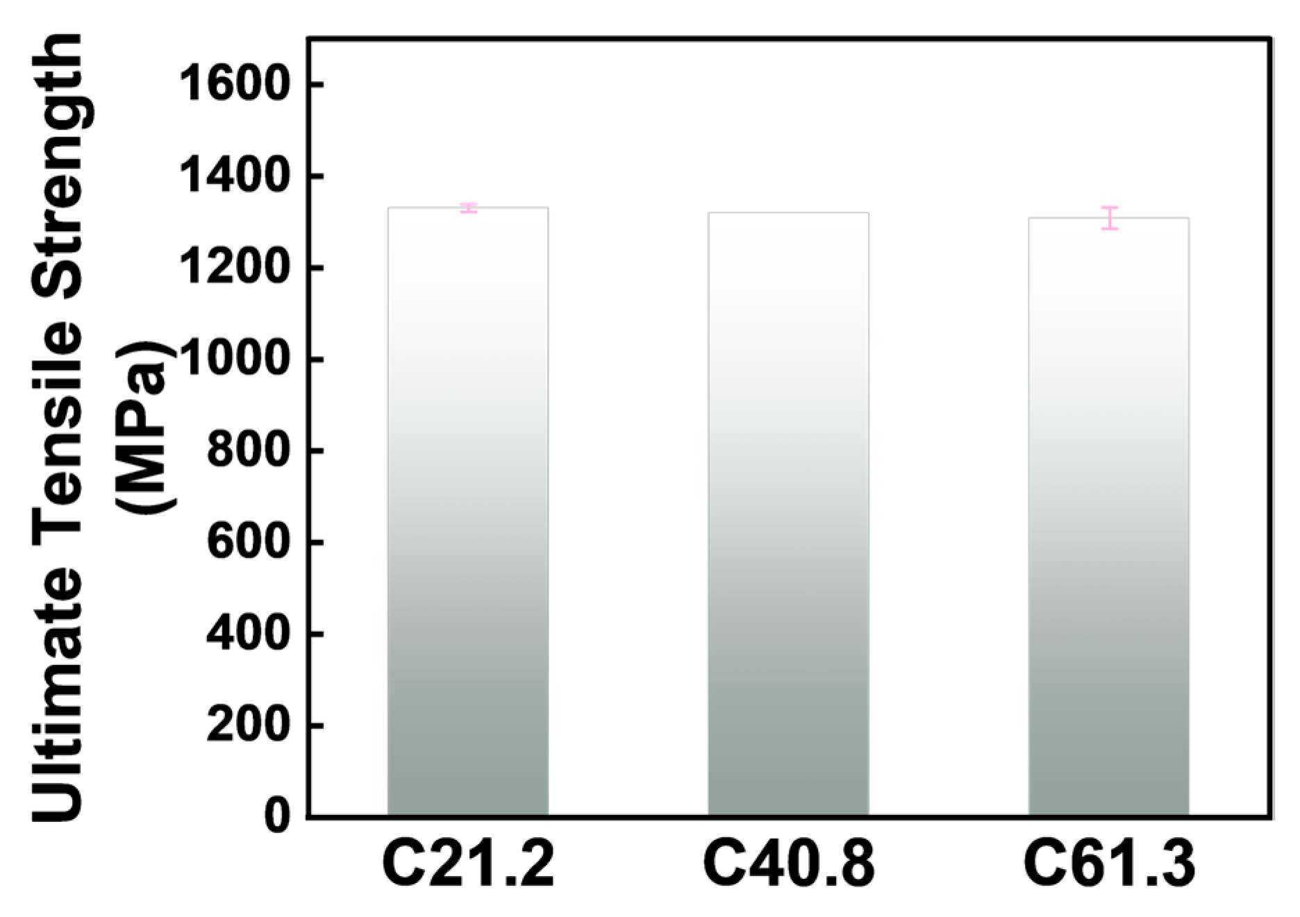
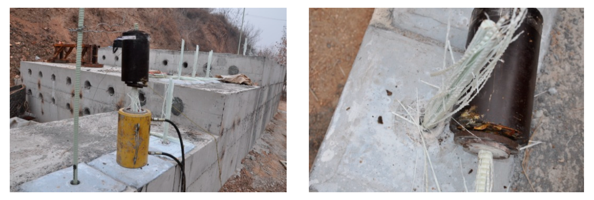
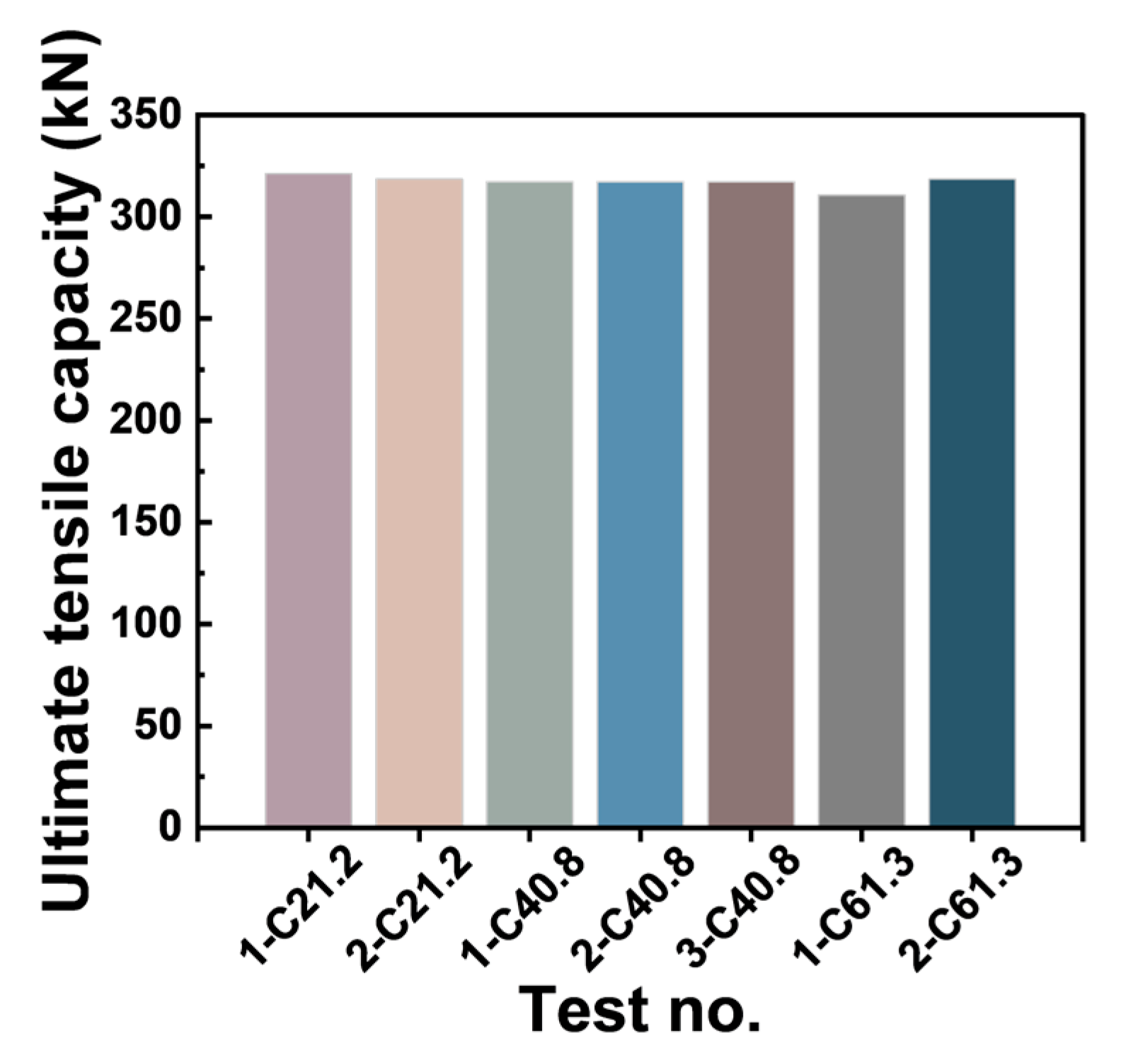
- Due to the high shear strength between the resin and the rod, as well as between the resin and the concrete, the results of the pullout tests for the seven GFRP resin bolts embedded in the three types of concrete blocks with different compressive strengths all exhibited rod fracture failure. The results showed that the failure mode was not controlled via the compressive strength of concrete blocks. The GFRP resin anchor system could fully utilize the tensile capacity of the GFRP rods. It can provide reference and guidance for practical engineering applications.
Supplementary Materials
Author Contributions
Funding
Institutional Review Board Statement
Informed Consent Statement
Data Availability Statement
Conflicts of Interest
References
- Li, H.; Fu, J.; Chen, B.; Zhang, X.; Zhang, Z.; Lang, L. Mechanical properties of GFRP bolts and its application in tunnel face reinforcement. Materials 2023, 16, 2193. [Google Scholar] [CrossRef]
- Zhang, X.; Ou, J. Durability experimental research on resistance of acidic, alkali, salt solutions and freeze-thaw properties of FRP bar. J. Wuhan Univ. Technol. 2007, 29, 33–36. [Google Scholar] [CrossRef]
- Kajorncheappunngam, S.; Gupta, R.K.; GangaRao, H.V.S. Effect of aging environment on degradation of glass-reinforced epoxy. J. Compos. Constr. 2002, 6, 61–69. [Google Scholar] [CrossRef]
- Wang, J.; GangaRao, H.; Liang, R.; Liu, W. Durability and prediction models of fiber-reinforced polymer composites under various environmental conditions: A critical review. J. Reinf. Plast. Compos. 2016, 35, 179–211. [Google Scholar] [CrossRef]
- Tu, J.; Xie, H.; Gao, K. Prediction of the long-term performance and durability of GFRP bars under the combined effect of a sustained load and severe environments. Materials 2020, 13, 2341. [Google Scholar] [CrossRef]
- Lu, C.; Yang, Y.; He, L. Mechanical and durability properties of GFRP bars exposed to aggressive solution environments. Sci. Eng. Compos. Mater. 2021, 28, 11–23. [Google Scholar] [CrossRef]
- Kazemi, H.; Yekrangnia, M.; Shakiba, M.; Bazli, M.; Vatani Oskouei, A. Bond durability between anchored GFRP bar and seawater concrete under offshore environmental conditions. Mater. Struct. 2023, 56, 1–16. [Google Scholar] [CrossRef]
- Song, Z.; Lu, C.; Xuan, G.; Cai, Q.; Bu, S. Experimental and theoretical calculation of bonding performance between threaded GFRP bars and concrete. J. Build. Mater. 2021, 24, 887–894. [Google Scholar]
- Zhang, X.; Li, H.; Zhang, Z.; Deng, L. Study on bond performance parameters of GFRP bars based on pull-out test. J. Sichuan Univ. (Nat. Sci. Ed.) 2021, 58, 125–130. [Google Scholar]
- Lee, J.-Y.; Lim, A.-R.; Kim, J.; Kim, J. Bond behaviour of GFRP bars in high-strength concrete: Bar diameter effect. Mag. Concr. Res. 2017, 69, 541–554. [Google Scholar] [CrossRef]
- Yan, F.; Jia, X.; Yuan, Y. Experiments on the bonding behaviour of GFRP bolts with mortar. Indus Constr. 2004, 34, 59–61. [Google Scholar]
- Zingano, A.; Peng, S.; Koppe, J.; Costa, J.F. In-situ tests and numerical simulation about the effect of annulus thickness on the resin mixture for fully grouted resin bolt. Soils Rocks 2012, 35, 153–160. [Google Scholar] [CrossRef]
- Xue, W.; Zhang, S.; Kang, M. Bond strength of glass fiber-reinforced polymer ground anchors with helically wound ribs rebars in different bonding agents. Mater. Res. Innov. 2015, 19, 449–453. [Google Scholar] [CrossRef]
- Okelo, R.; Yuan, R. Bond strength of fiber reinforced polymer rebars in normal strength concrete. J. Compos. Constr. 2005, 9, 203–213. [Google Scholar] [CrossRef]
- Lee, J.; Kim, T.; Kim, T.; Yi, C.; Park, J.; You, Y.; Park, Y. Interfacial bond strength of glass fiber reinforced polymer bars in high-strength concrete. Compos. Part B Eng. 2008, 39, 258–270. [Google Scholar] [CrossRef]
- Wang, W. Mechanical research on reinforced concrete materials. Materials 2023, 16, 6892. [Google Scholar] [CrossRef]
- Ning, H.; Ren, H.; Wang, W.; Nie, X. Impact resistance on ultra-high-performance concrete composite structures. Materials 2023, 16, 7456. [Google Scholar] [CrossRef]
- Rolland, A.; Benzarti, K.; Quiertant, M.; Chataigner, S. Accelerated aging behavior in alkaline environments of GFRP reinforcing bars and their bond with concrete. Materials 2021, 14, 5700. [Google Scholar] [CrossRef]
- Wang, Y.; Feng, J.; Li, J.; Lai, B.; Yang, T. Advance of FRP anchor bolts in geotechnical anchoring. Chin. J. Eng. Geol. 2018, 26, 776–784. [Google Scholar]
- Liu, Y.; Yuan, Y. Experimental research on anchorage performance of full-thread GFRP bonding anchor bolts. Chin. J. Rock Mech. Eng. 2010, 29, 394–400. [Google Scholar]
- Huang, Z.; Li, G.; Wang, S.; Li, W. Field test on pullout behaviors of anchorage structures with glass fiber reinforced plastic rods for different surrounding rock masses. Chin. J. Rock Mech. Eng. 2008, 27, 1008–1018. [Google Scholar]
- Liu, J.; Wang, Z. Study on the application of fiber reinforced polymer bars in civil engineering. Chem. Eng. Trans. 2017, 59, 481–486. [Google Scholar]
- Benmokrane, B.; Xu, H.; Bellavance, E. Bond strength of cement grouted glass fiber reinforced plastic(GFRP) anchor bolts. Int. J. Rock Mech. Min. Sci. 1996, 33, 455–465. [Google Scholar] [CrossRef]
- Benmokrane, B.; Zhang, B.; Chennouf, A. Tensile properties and pullout behavior of AFRP and CFRP Rods for grouted anchor applications. Constr. Build. Mater. 2000, 14, 157–170. [Google Scholar] [CrossRef]
- Wu, Z.; Yang, S.; Zheng, J.; Hu, X. Analytical solution for the pull-out response of FRP rods embedded in steel tubes filled with cement grout. Mater. Struct. 2010, 43, 597–609. [Google Scholar] [CrossRef]
- GB/T 699-2015; Quality Carbon Structure Steels. Standardization Administration of the People’s Republic of China: Beijing, China, 2015.
- GB/T 50107-2019; Standard for Evaluation of Concrete Compressive Strength. Ministry of Housing and Urban-Rural Development of the People’s Republic of China, China Architecture & Building Press: Beijing, China, 2010.
- Feng, J.; Wang, Y.; Wu, H.; Lai, B.; Xie, X. Field pullout tests of basalt fiber-reinforced polymer ground anchor. Chin. J. Eng. Geol. 2019, 40, 2563–2573. [Google Scholar]
- Sun, G.; Bai, X.; Sang, S.; Zeng, L.; Yin, J.; Jing, D.; Zhang, M.; Yan, N. Numerical Simulation of anchorage performance of GFRP bolt and concrete. Buildings 2023, 13, 493. [Google Scholar] [CrossRef]


| Number | Water:Salt:Sulfuric Acid | pH |
|---|---|---|
| 1 | 100:0:0 | 7.20 |
| 2 | 100:15:0 | 9.34 |
| 3 | 100:30:0 | 9.86 |
| 4 | 100:15:15 | 0.57 |
| 5 | 100:0:15 | 0.55 |
| 6 | 100:0:30 | 0.19 |
| Nominal Diameter (mm) | Tensile Strength (MPa) | Torque (N·m) | Shear Strength (MPa) | Area (mm2) | Weight (kg/m) |
|---|---|---|---|---|---|
| 22 | 900 | 90 | 140 | 240.4 | 0.683 |
| Compressive Strength (MPa) | Flexural Strength (MPa) | Splitting Tensile Strength (MPa) | Bond Strength (MPa) |
|---|---|---|---|
| 57.4 | 21.8 | 10.1 | 5.6 |
| Corrosive Solution | Water:Salt:Sulfuric Acid (by Weight) | Number of GFRP Bars | Anchoring Agent Block |
|---|---|---|---|
| 1 | 100:0:0 | 3 | - |
| 2 | 100:15:0 | - | 15 |
| 3 | 100:30:0 | 3 | 15 |
| 4 | 100:15:15 | 3 | 15 |
| 5 | 100:0:15 | - | 15 |
| 6 | 100:0:30 | 3 | 15 |
| Total | - | 12 | 75 |
| Corrosive Solution | Water:Salt:Sulfuric Acid (by Weight) | Tensile Strength (MPa) | Elastic Modulus (MPa) | Elongation Rate (%) |
|---|---|---|---|---|
| 1 | 100:0:0 | 1139.00 | 4.48 × 10⁴ | 2.14 |
| 3 | 100:30:00 | 1102.51 | 4.33 × 10⁴ | 2.12 |
| 4 | 100:15:15 | 1120.76 | 4.41 × 10⁴ | 2.29 |
| 6 | 100:00:30 | 1138.09 | 4.37 × 10⁴ | 2.11 |
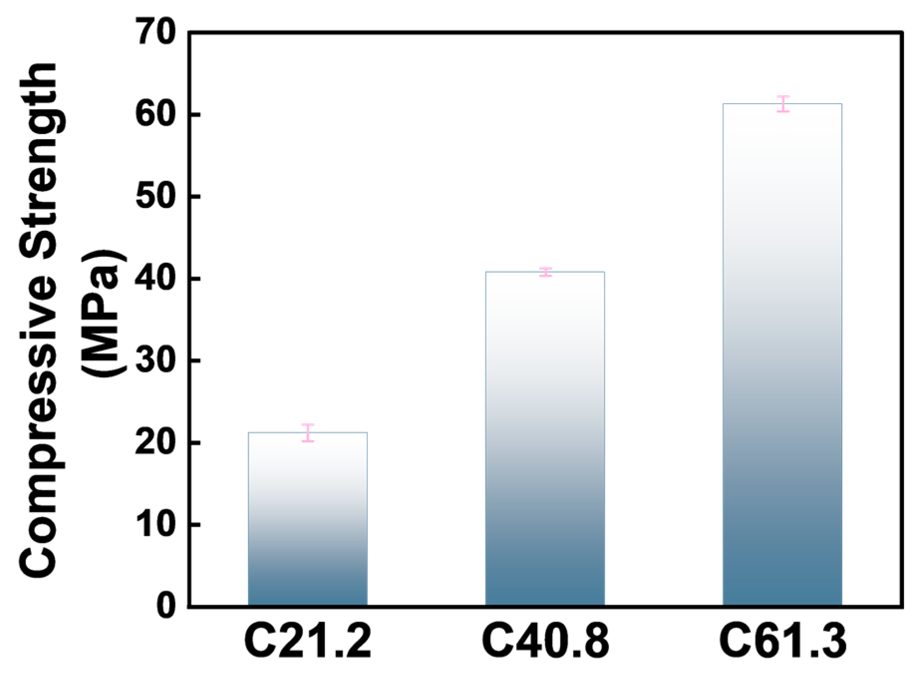
| Specimen Number | Pressure (ton) | Specimen Size | Compressive Strength (MPa) | Average Compressive Strength (MPa) |
|---|---|---|---|---|
| C20-1 | 48 | 150 mm × 150 mm × 150 mm | 21.3 | 21.2 |
| C20-2 | 51 | 22.6 | ||
| C20-3 | 50 | 22.2 | ||
| C20-4 | 46 | 20.4 | ||
| C20-5 | 45 | 20.0 | ||
| C20-6 | 47 | 20.9 | ||
| C40-1 | 91 | 40.4 | 40.8 | |
| C40-2 | 93 | 41.3 | ||
| C40-3 | 92 | 40.8 | ||
| C60-1 | 140 | 62.2 | 61.3 | |
| C60-2 | 136 | 60.4 | ||
| C60-3 | 138 | 61.3 |
| Diameter (mm) | Anchor Length (cm) | Ultimate Pull Load (kN) | Failure Mode |
|---|---|---|---|
| 22 | 10 | 150.13 | Slip between the rod and resin |
| 22 | 15 | 271.18 | Rod fracture |
| 22 | 20 | 263.29 | Rod fracture |
| 22 | 30 | 271.18 | Rod fracture |
| Anchor Number | Ultimate Pullout Force (KN) | Ultimate Tensile Strength (MPa) | Average Ultimate Tensile Strength (MPa) |
|---|---|---|---|
| 1-C21.2 | 321.18 | 1336.04 | 1330.56 |
| 2-C21.2 | 318.55 | 1325.09 | |
| 1-C40.8 | 317.24 | 1319.62 | 1319.62 |
| 2-C40.8 | 317.24 | 1319.62 | |
| 3-C40.8 | 317.24 | 1319.62 | |
| 1-C61.3 | 310.66 | 1292.25 | 1308.67 |
| 2-C61.3 | 318.55 | 1325.09 |
Disclaimer/Publisher’s Note: The statements, opinions and data contained in all publications are solely those of the individual author(s) and contributor(s) and not of MDPI and/or the editor(s). MDPI and/or the editor(s) disclaim responsibility for any injury to people or property resulting from any ideas, methods, instructions or products referred to in the content. |
© 2024 by the authors. Licensee MDPI, Basel, Switzerland. This article is an open access article distributed under the terms and conditions of the Creative Commons Attribution (CC BY) license (https://creativecommons.org/licenses/by/4.0/).
Share and Cite
Lin, M.; Zhang, F.; Wang, W. Experimental Study on Durability and Bond Properties of GFRP Resin Bolts. Materials 2024, 17, 2814. https://doi.org/10.3390/ma17122814
Lin M, Zhang F, Wang W. Experimental Study on Durability and Bond Properties of GFRP Resin Bolts. Materials. 2024; 17(12):2814. https://doi.org/10.3390/ma17122814
Chicago/Turabian StyleLin, Mingan, Fuming Zhang, and Wei Wang. 2024. "Experimental Study on Durability and Bond Properties of GFRP Resin Bolts" Materials 17, no. 12: 2814. https://doi.org/10.3390/ma17122814
APA StyleLin, M., Zhang, F., & Wang, W. (2024). Experimental Study on Durability and Bond Properties of GFRP Resin Bolts. Materials, 17(12), 2814. https://doi.org/10.3390/ma17122814