


Influence of Chloride Concentration on Fretting Wear Behavior of Inconel 600 Alloy


Abstract
1. Introduction
2. Materials and Methods
3. Results and Discussion
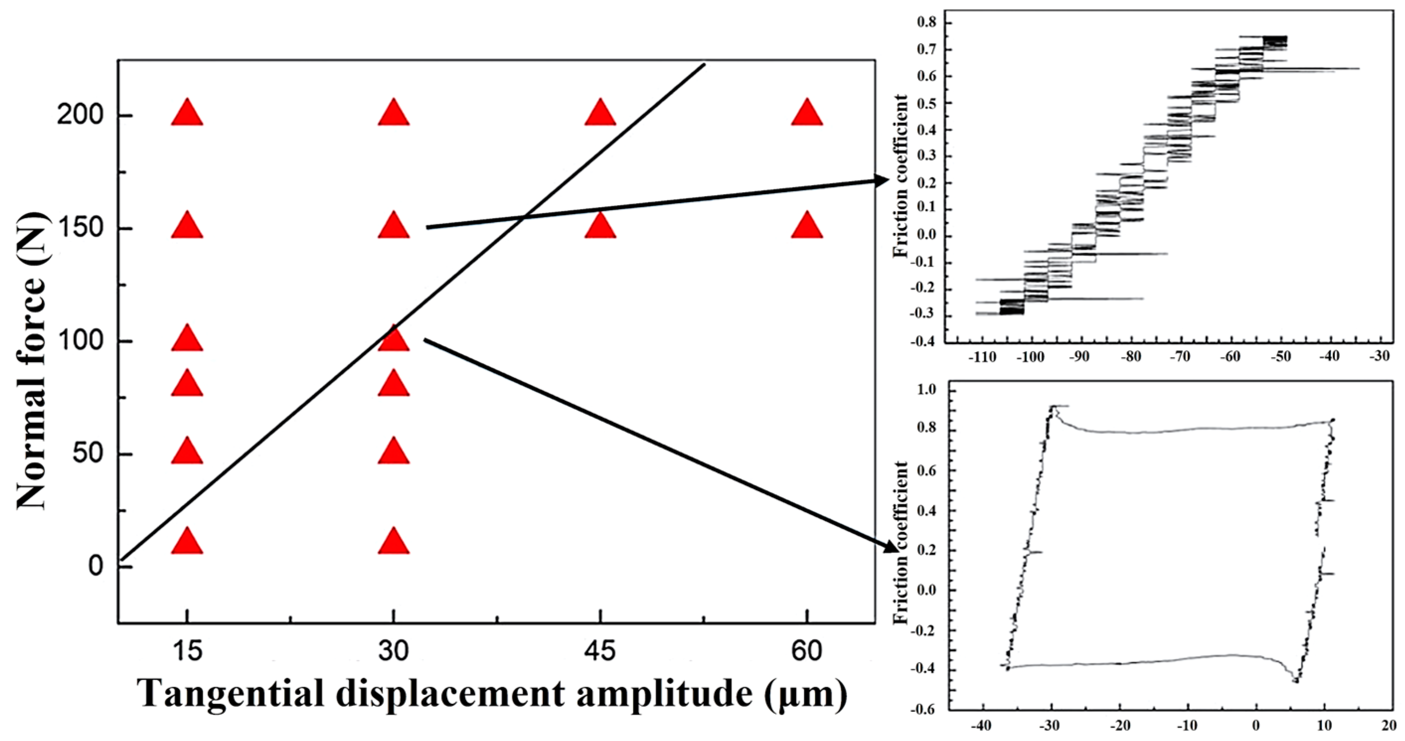
3.1. Running Condition Fretting Map in Water Environment
3.2. Effect of Fretting Wear Behavior in Different Cl− Concentrations
3.2.1. The Fretting Regimes in GSR
3.2.2. The Fretting Regimes in PSR
4. Conclusions
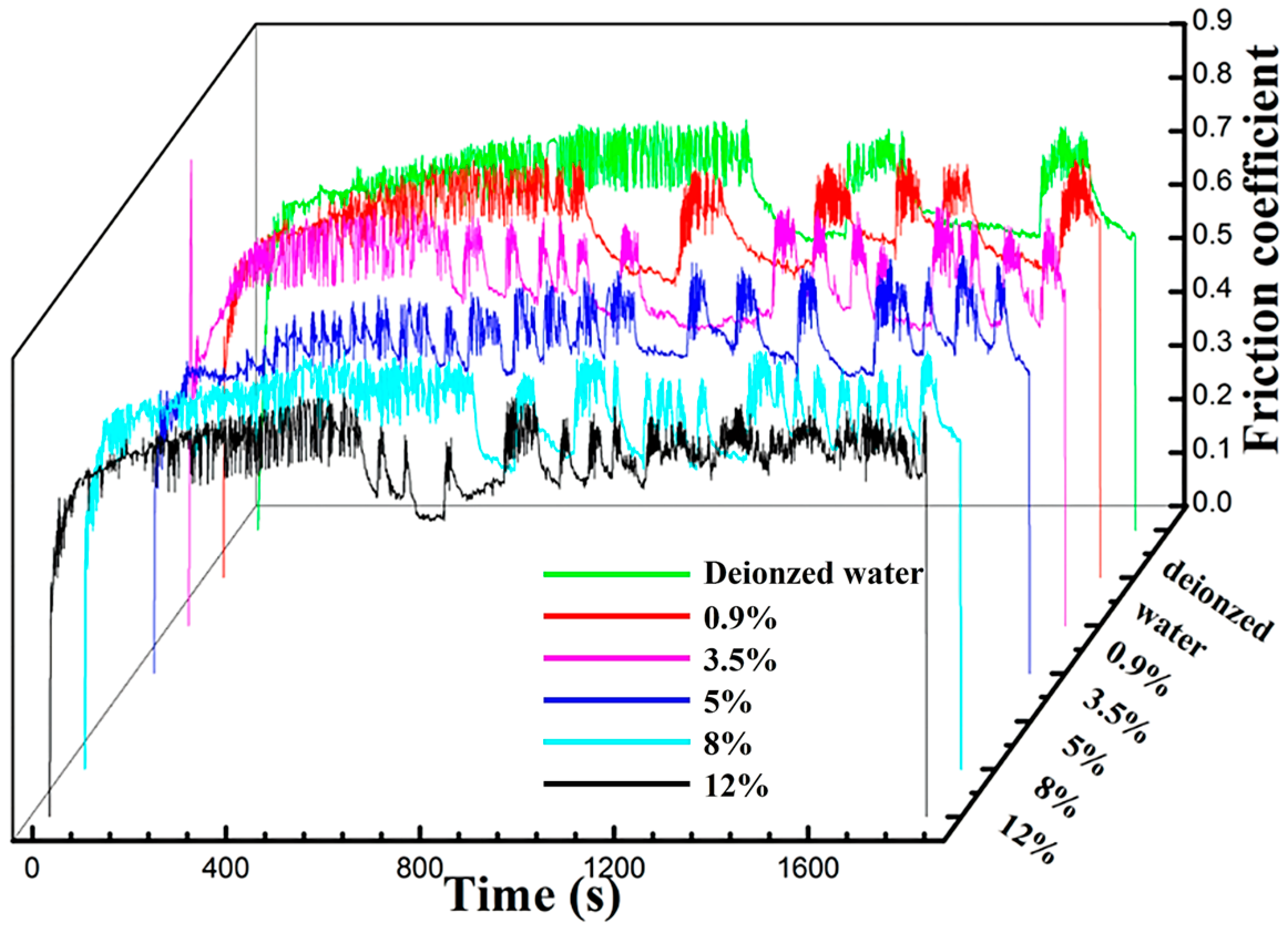
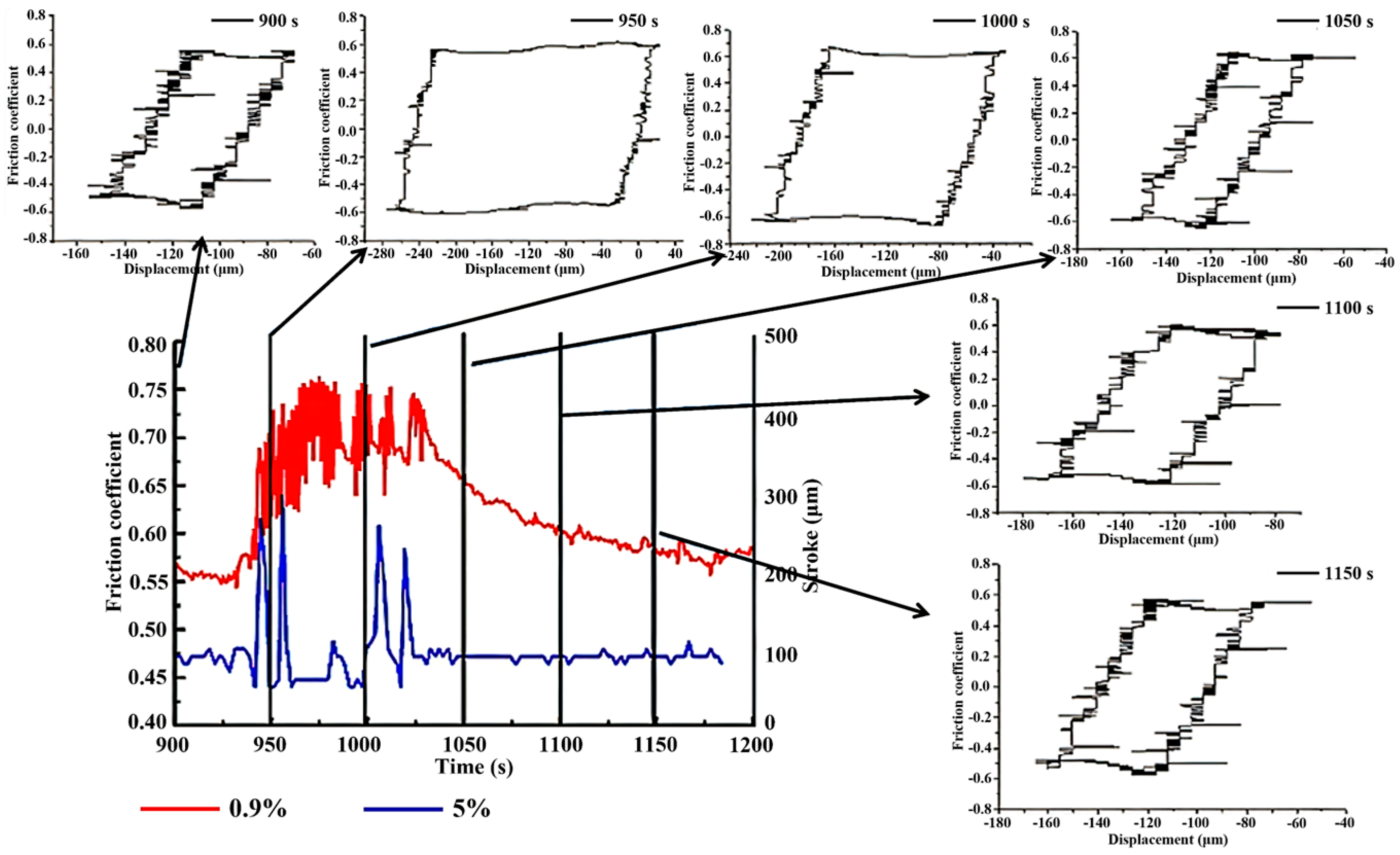
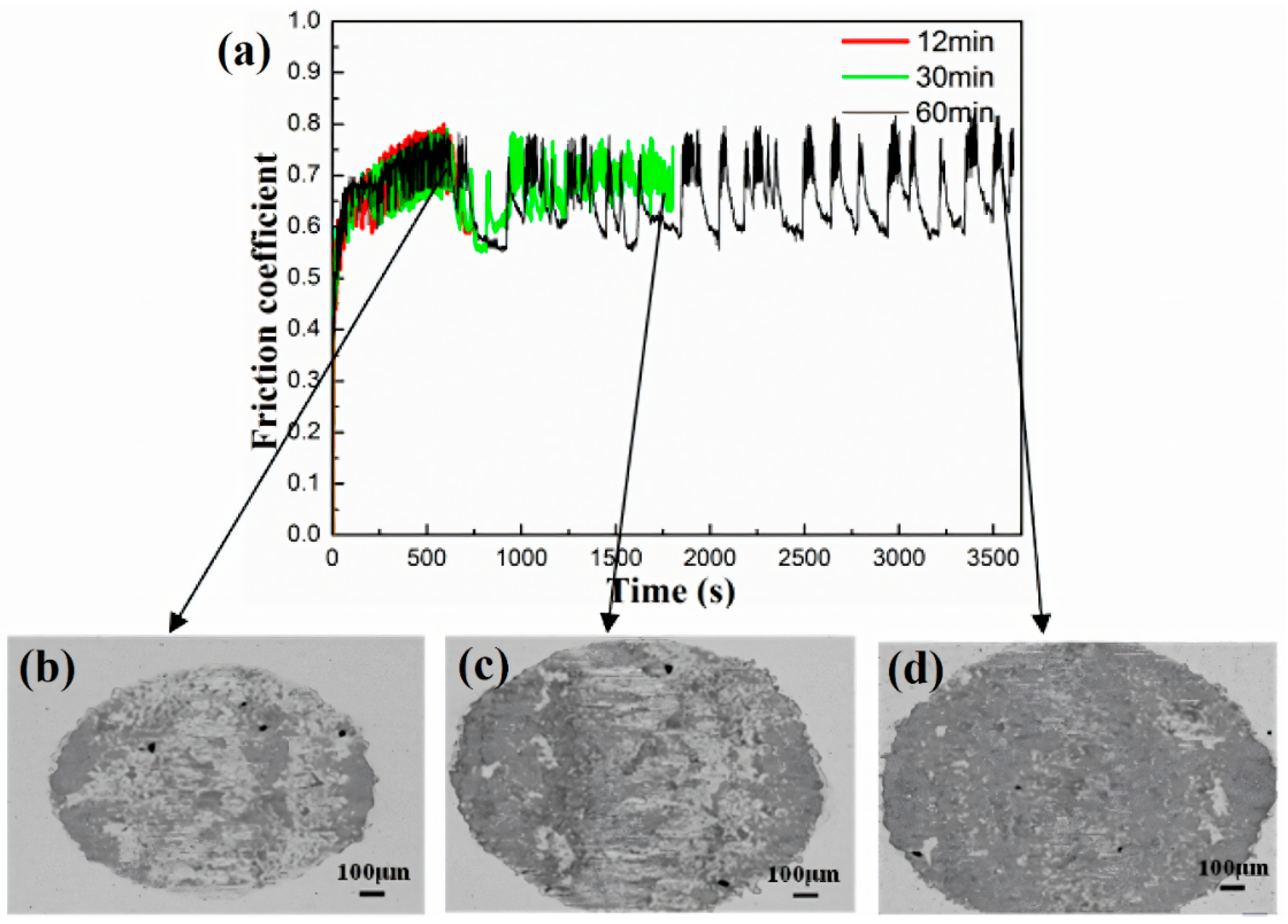
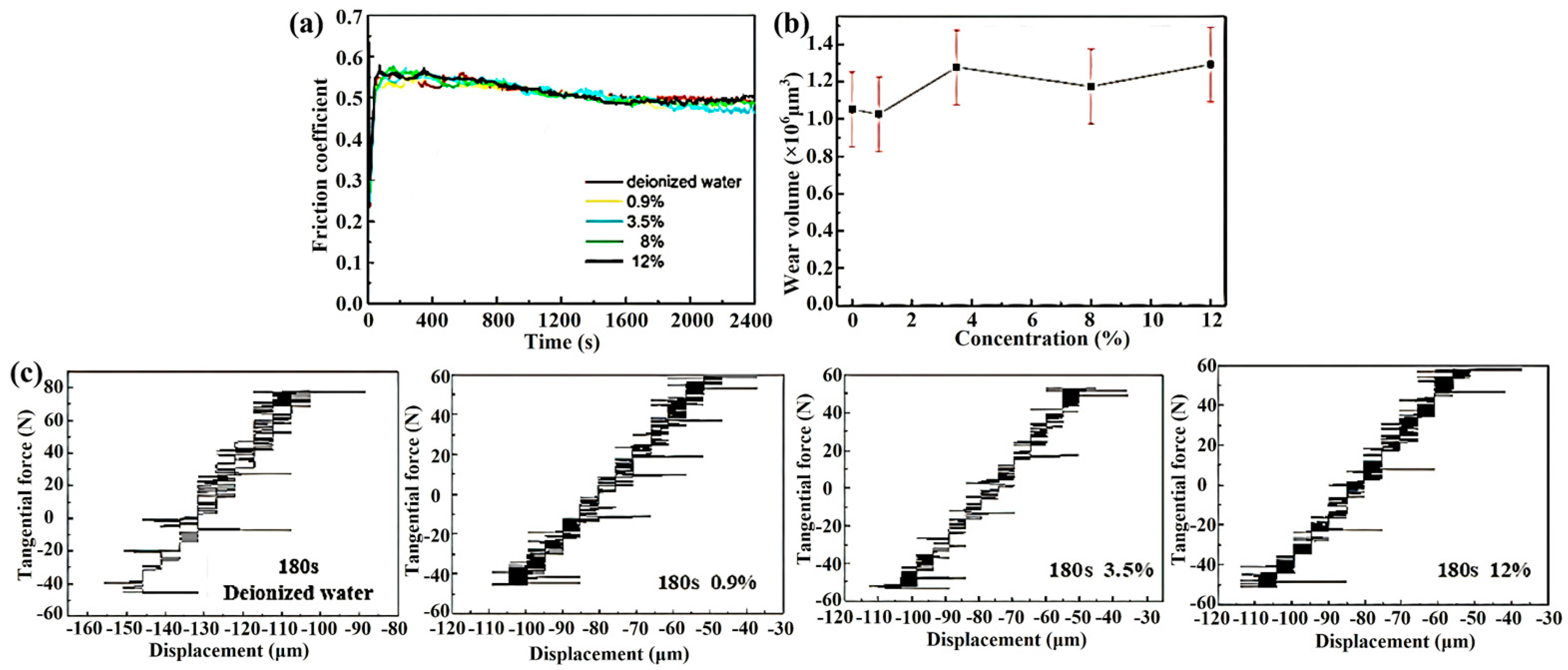
- The variation in Cl− concentration was found to exert a significant influence on fretting wear behaviors. As the Cl− concentration increased, notable changes were observed in the fretting characteristics. Specifically, the onset time of friction coefficient fluctuation advanced progressively, indicating an earlier onset of wear-related instabilities. Concurrently, the wear volume exhibited a gradual increase with an increasing Cl− concentration, suggesting a heightened propensity for material loss under more corrosive conditions.
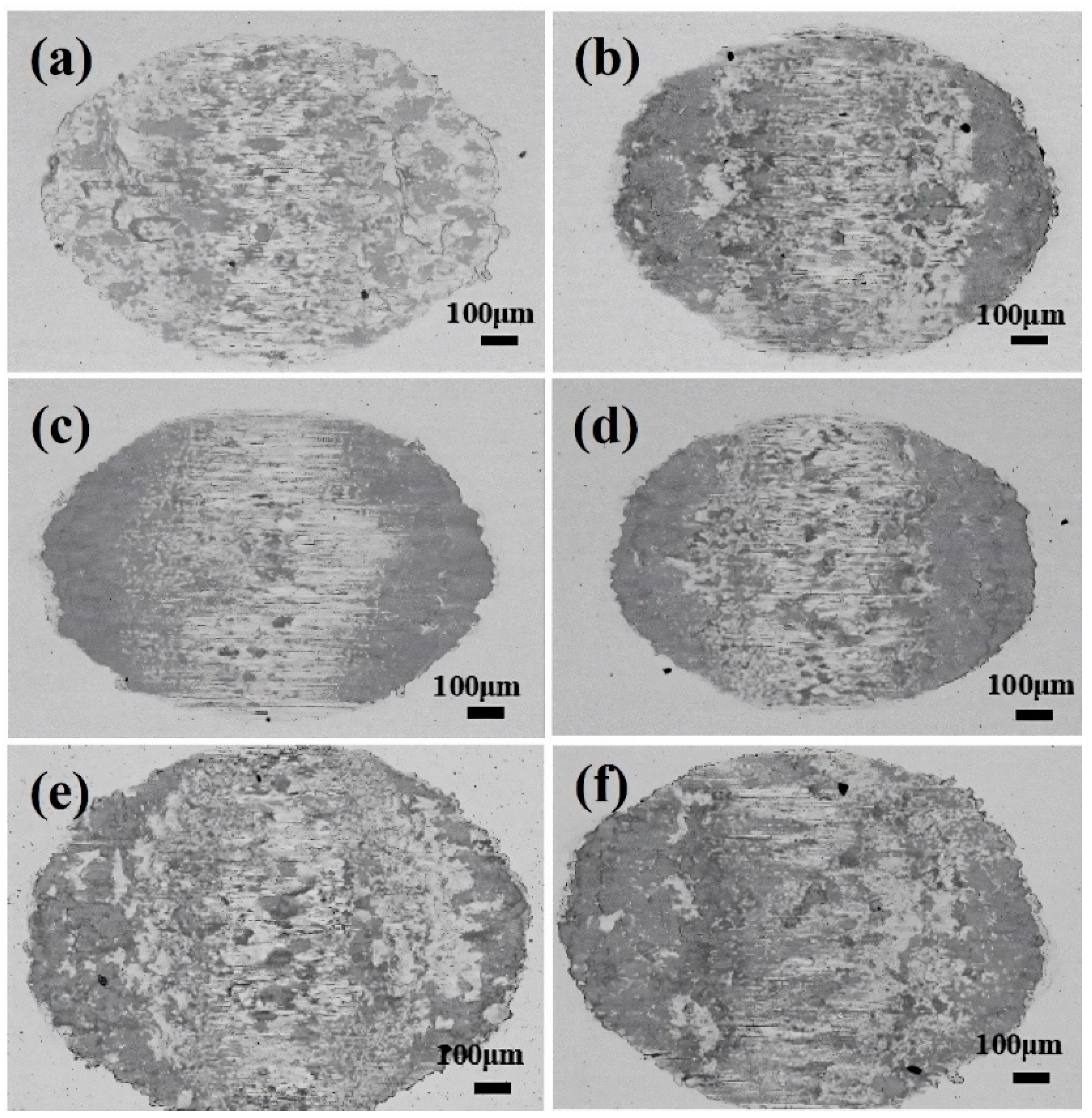
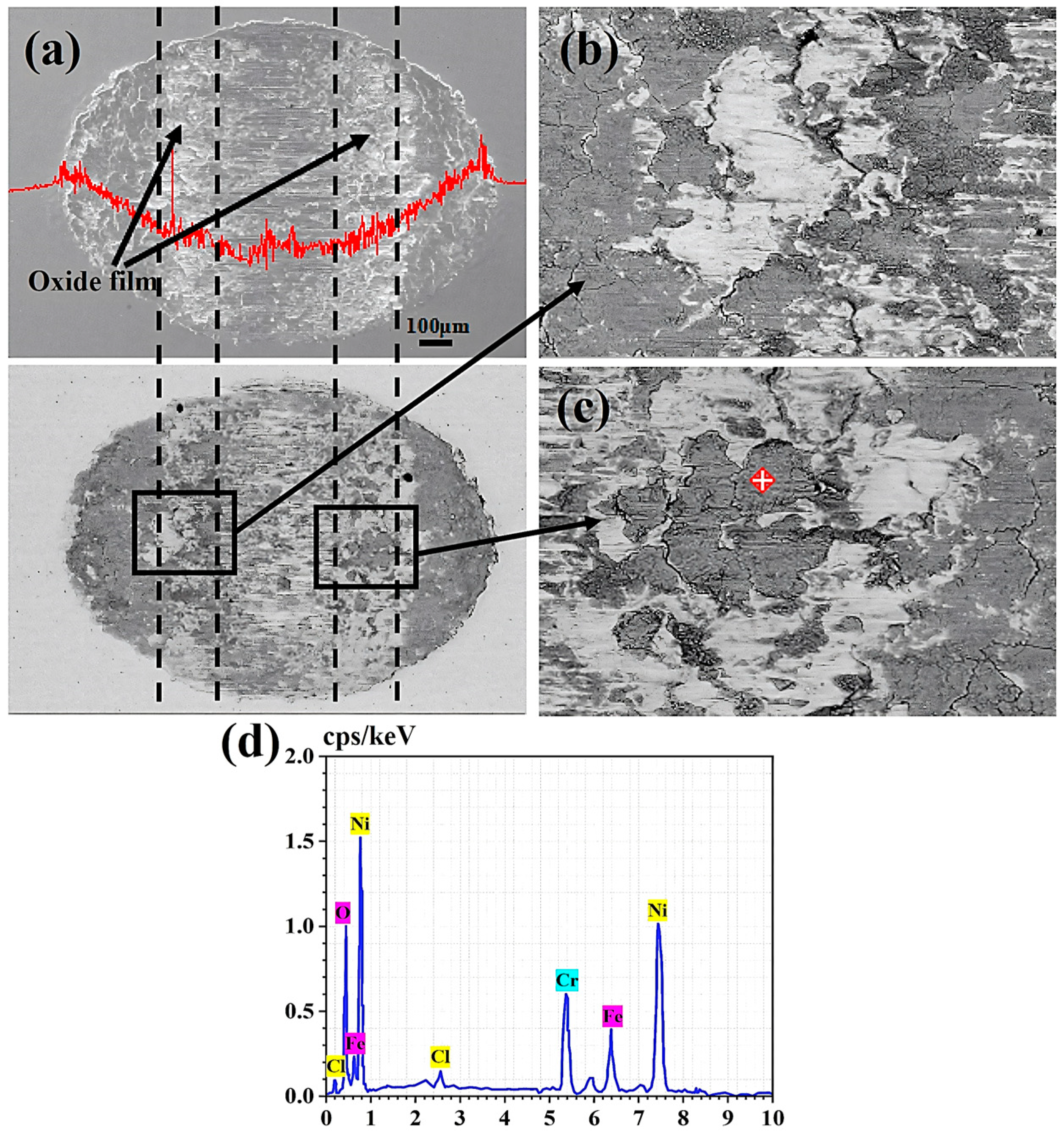
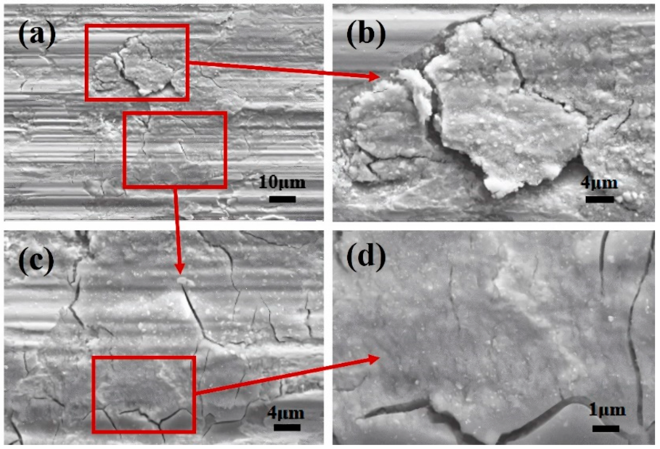
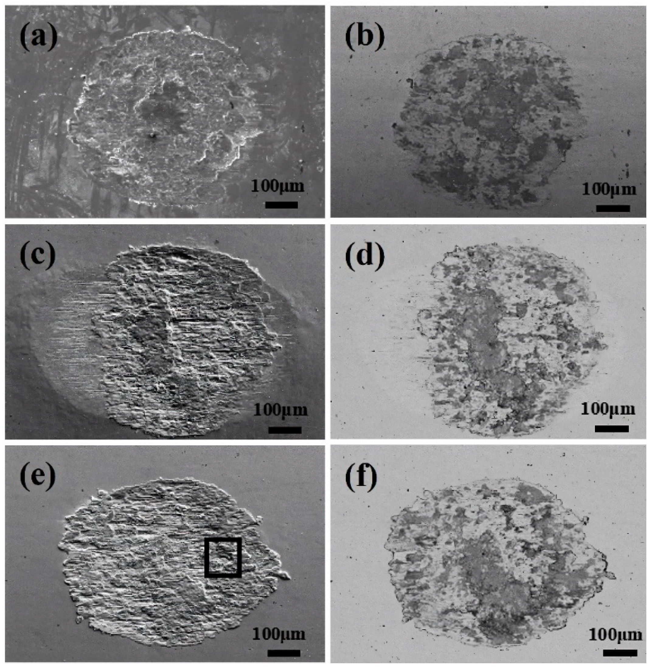
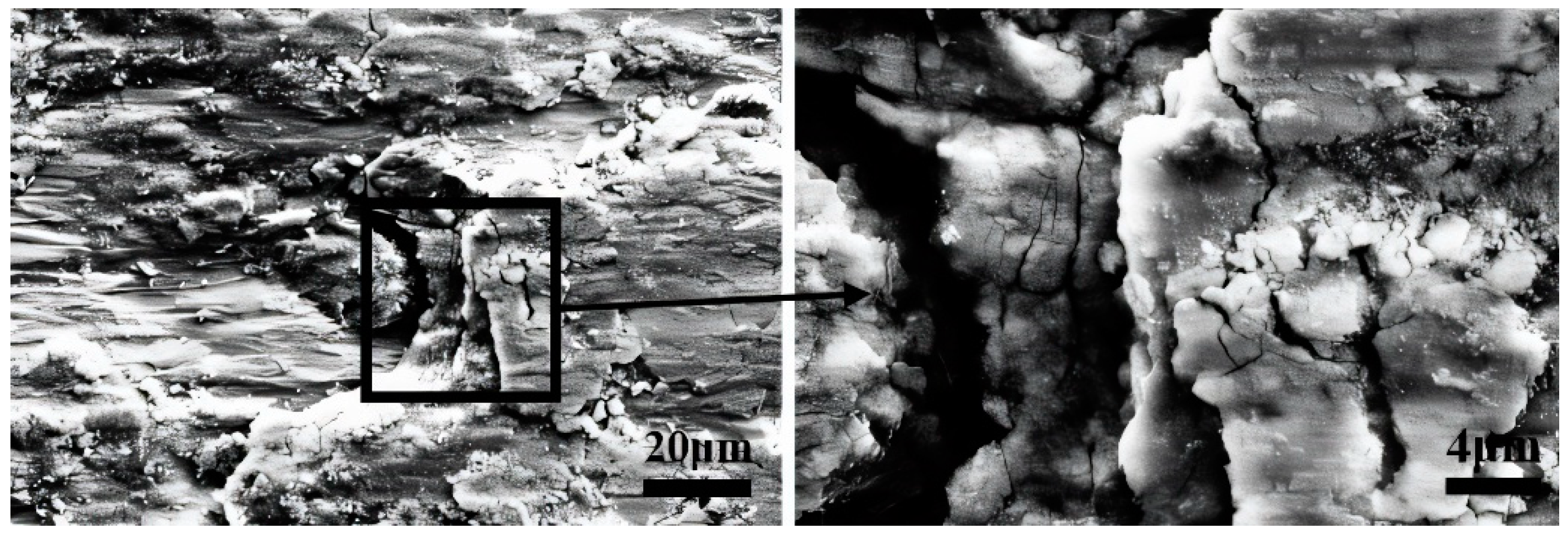
- In GSR, the influence of Cl− concentration was notable. As the Cl− concentration increased, the oxide layer on the worn surface tended to peel off, hindering the formation of a cohesive and protective oxide layer. Consequently, the wear mechanism transitioned gradually from abrasive wear to oxidation wear and delamination.
- In PSR, the impact of Cl− concentration on wear behavior was less pronounced compared to the GSR. The wear volume exhibited minimal sensitivity to changes in Cl− concentration and remained notably lower than that observed in GSR. Moreover, the FC in PSR demonstrated relative stability without oscillatory behavior.
Author Contributions
Funding
Institutional Review Board Statement
Informed Consent Statement
Data Availability Statement
Acknowledgments
Conflicts of Interest
References
- Zhang, P.; Zeng, L.; Mi, X.; Lu, Y.; Luo, S.; Zhai, W. Comparative study on the fretting wear property of 7075 aluminum alloys under lubricated and dry conditions. Wear 2021, 474–475, 203760. [Google Scholar] [CrossRef]
- Baêta, D.A.; Costa, D.J.R.; Cardoso, F.G.; Medeiros, N. Evaluation of fretting wear occurrence on the surface of nuclear fuel rods of Zr–1Nb–1Sn-0.1Fe alloy: Effects of assembly misalignment and grid spring loading. Wear 2020, 460–461, 203422. [Google Scholar] [CrossRef]
- Li, J.; Shen, H.; Wang, Y.; Peng, Z.; Liu, J.; Ren, Q.; Huang, H.; Liao, Y. Fretting wear behaviors of Cr-coated Zr–1Nb alloy cladding tube mated with Zr-4 alloy dimple under different tangential displacements. Wear 2024, 546–547, 205362. [Google Scholar] [CrossRef]
- Zhang, C.-Z.; Shen, F.; Ke, L.-L. A comparative study on the electrical contact behavior of CuZn40 and AgCu10 alloys under fretting wear: Effect of current load. Tribol. Int. 2024, 194, 109523. [Google Scholar] [CrossRef]
- Liu, H.; Chen, J.; Wan, F.; Zhang, Y.; Tian, X.; Yan, Y. Influence of protein migration on the fretting-corrosion behavior of 316 L stainless steel with artificial crevices. Corros. Sci. 2024, 230, 111924. [Google Scholar] [CrossRef]
- Park, G.S.; Kim, G.G.; Kim, S.J. Sliding wear behaviors of steam generator tube materials in high temperature water environment. J. Nucl. Mater. 2006, 352, 80–84. [Google Scholar] [CrossRef]
- Soria, S.R.; Tolley, A.; Yawny, A. A study of debris and wear damage resulting from fretting of Incoloy 800 steam generator tubes against AISI Type 304 stainless steel. Wear 2016, 368–369, 219–229. [Google Scholar] [CrossRef]
- Soria, S.R.; Claramonte, S.; Yawny, A. Evolution of fretting wear with the number of cycles on Inconel 690 steam generator tubes against AISI 420 steel under gross slip conditions. Tribol. Int. 2021, 155, 106803. [Google Scholar] [CrossRef]
- Guo, X.; Lai, P.; Li, L.; Tang, L.; Zhang, L. Progress in studying the fretting wear/corrosion of nuclear steam generator tubes. Ann. Nucl. Energy 2020, 144, 107556. [Google Scholar] [CrossRef]
- Liu, X.; Xu, D.; Lin, J.; Zhang, L.; Zeng, Y.; Chen, Q. Failure analysis and factors influencing spline wear in hydraulic motors of charging pumps in nuclear power plants. Eng. Fail. Anal. 2024, 156, 107780. [Google Scholar] [CrossRef]
- Hua, K.; Cao, Y.; Yu, X.; Huang, Q.; Tong, Y.; Wang, Y.; Zhang, F.; Wu, H.; Wang, X.-Z.; Wang, H. Investigation on fretting wear mechanism of 316 stainless steel induced by Ni dissolution during pre-immersion corrosion in the liquid lead-bismuth eutectic (LBE). Tribol. Int. 2022, 174, 107772. [Google Scholar] [CrossRef]
- Peng, J.; Ding, S.; He, Z.; Li, B.; He, J.; Liu, J.; Zhu, M. Study on bi-directional composite fretting wear characteristics of Zr-4 alloy tube with different phase differences under temperature conditions. Tribol. Int. 2024, 191, 109139. [Google Scholar] [CrossRef]
- Jung, E.-J.; Lee, H.-W. Comparison of Corrosion Resistance and Corroded Surfaces of Welding Metal in Overlay-Welded Inconel 600 and Inconel 625 by Gas Metal Arc Welding. Int. J. Electrochem. Sci. 2016, 11, 7125–7138. [Google Scholar] [CrossRef]
- Yang, T.; Zhang, G.; Dai, Z.; Liang, X.; Wang, Y.; Su, Y. Corrosion behavior of N-containing low Ni deposited metal and Inconel 625 deposited metal in 40 mol% MgCl2 + 60 mol% KCl molten salt at 600 °C. Mater. Lett. 2024, 357, 135636. [Google Scholar] [CrossRef]
- Jiang, Y.; Jiang, G.; Sun, J.; Zhang, W.; Liu, Y. Characterization of leakage jet flow field and wall vibration of steam generator pipes. Nucl. Eng. Des. 2024, 423, 113225. [Google Scholar] [CrossRef]
- Lee, Y.-H.; Kim, I.-S. The effect of subsurface deformation on the wear behavior of steam generator tube materials. Wear 2002, 253, 438–447. [Google Scholar] [CrossRef]
- Jeong, S.-H.; Cho, C.-W.; Lee, Y.-Z. Friction and wear of Inconel 690 for steam generator tube in elevated temperature water under fretting condition. Tribol. Int. 2005, 38, 283–288. [Google Scholar] [CrossRef]
- Li, J.; Lu, Y.H. Effects of displacement amplitude on fretting wear behaviors and mechanism of Inconel 600 alloy. Wear 2013, 304, 223–230. [Google Scholar] [CrossRef]
- Lim, M.-K.; Oh, S.-D.; Lee, Y.-Z. Friction and wear of Inconel 690 and Inconel 600 for steam generator tube in room temperature water. Nucl. Eng. Des. 2003, 226, 97–105. [Google Scholar] [CrossRef]
- Vingsbo, O.; Söderberg, S. On fretting maps. Wear 1988, 126, 131–147. [Google Scholar] [CrossRef]
- Garcin, S.; Fouvry, S.; Heredia, S. A FEM fretting map modeling: Effect of surface wear on crack nucleation. Wear 2015, 330–331, 145–159. [Google Scholar] [CrossRef]
- Lee, C.Y.; Tian, L.S.; Bae, J.W.; Chai, Y.S. Application of influence function method on the fretting wear of tube-to-plate contact. Tribol. Int. 2009, 42, 951–957. [Google Scholar] [CrossRef]
- Zhou, Z.R.; Nakazawa, K.; Zhu, M.H.; Maruyama, N.; Kapsa, P.; Vincent, L. Progress in fretting maps. Tribol. Int. 2006, 39, 1068–1073. [Google Scholar] [CrossRef]
- Singh, K.; Mahato, A.; Tiwari, M. Transition from mixed stick-slip to gross-slip regime in fretting. Tribol. Int. 2022, 165, 107338. [Google Scholar] [CrossRef]
- Zhang, S.; Liu, L.; Bonzom, R.; Mi, X.; Tan, W.; Zhu, G. Electrochemical study on the fretting corrosion synergistic damage mechanism of Inconel 690 alloy in different dissolved oxygen solution. Electrochim. Acta 2024, 474, 143530. [Google Scholar] [CrossRef]
- Wang, Z.H.; Lu, Y.H.; Li, J.; Shoji, T. Effect of pH value on the fretting wear behavior of Inconel 690 alloy. Tribol. Int. 2016, 95, 162–169. [Google Scholar] [CrossRef]
- Park, J.-J.; Pyun, S.-I. Stochastic approach to the pit growth kinetics of Inconel alloy 600 in Cl− ion-containing thiosulphate solution at temperatures 25–150 °C by analysis of the potentiostatic current transients. Corros. Sci. 2004, 46, 285–296. [Google Scholar] [CrossRef]
- Grégoire, B.; Oskay, C.; Meißner, T.M.; Galetz, M.C. Corrosion mechanisms of ferritic-martensitic P91 steel and Inconel 600 nickel-based alloy in molten chlorides. Part I: NaCl–KCl binary system. Sol. Energy Mater. Sol. Cells 2020, 215, 110659. [Google Scholar] [CrossRef]
- Li, J.; Lu, Y.; Zhang, H.; Xin, L. Effect of grain size and hardness on fretting wear behavior of Inconel 600 alloys. Tribol. Int. 2015, 81, 215–222. [Google Scholar] [CrossRef]
- Soria, S.R.; Tolley, A.; Yawny, A. Characterization of damage and triboparticles resulting from fretting of Incoloy 800 steam generator tubes against different materials. Wear 2017, 390, 198–208. [Google Scholar] [CrossRef]
- Xin, L.; Han, Y.; Lu, Y.; Shoji, T. Investigation on the Fretting Wear Behavior and Mechanisms of Alloy 690TT during the Transformation from Mixed Regime to Partial Slip Regime Induced by Elevated Temperature. Tribol. Trans. 2019, 62, 464–475. [Google Scholar] [CrossRef]
- Xin, L.; Wang, Z.H.; Li, J.; Lu, Y.H.; Shoji, T. Fretting Wear Behavior and Mechanism of Inconel 690 Alloy Related to the Displacement Amplitude. Tribol. Trans. 2017, 60, 913–922. [Google Scholar] [CrossRef]
- Zhou, Z.R.; Vincent, L. Mixed fretting regime. Wear 1995, 181–183, 531–536. [Google Scholar] [CrossRef]
- Zhang, Y.; Ming, H.; Lai, J.; Gao, L.; Wang, J.; Han, E.-H. Fretting wear behavior of Zr alloy cladding tube mated with Zr alloy dimple under mixed fretting regime in simulated primary water of PWR. J. Mater. Sci. Technol. 2023, 158, 43–52. [Google Scholar] [CrossRef]
- Chang, M.-Y.; Yu, G.-P. Pitting corrosion of inconel 600 in chloride and sulfate solutions at low temperature. J. Nucl. Mater. 1993, 202, 145–153. [Google Scholar] [CrossRef]
- Xin, L.; Huang, Q.; Han, Y.; Ji, H.; Lu, Y.; Shoji, T. Insights into the fatigue cracking of Alloy 690TT subjected to fretting wear under partial slip conditions. Mater. Charact. 2020, 159, 110040. [Google Scholar] [CrossRef]
- Warmuth, A.R.; Shipway, P.H.; Sun, W. Fretting wear mapping: The influence of contact geometry and frequency on debris formation and ejection for a steel-on-steel pair. Proc. R. Soc. A Math. Phys. Eng. Sci. 2015, 471, 20140291. [Google Scholar] [CrossRef]
- Dréano, A.; Fouvry, S.; Guillonneau, G. A tribo-oxidation abrasive wear model to quantify the wear rate of a cobalt-based alloy subjected to fretting in low-to-medium temperature conditions. Tribol. Int. 2018, 125, 128–140. [Google Scholar] [CrossRef]
- Rynio, C.; Hattendorf, H.; Klöwer, J.; Eggeler, G. On the physical nature of tribolayers and wear debris after sliding wear in a superalloy/steel tribosystem at 25 and 300 °C. Wear 2014, 317, 26–38. [Google Scholar] [CrossRef]
- Zhou, Z.R.; Fayeulle, S.; Vincent, L. Cracking behaviour of various aluminium alloys during fretting wear. Wear 1992, 155, 317–330. [Google Scholar] [CrossRef]
- Xin, L.; Ma, M.; Lu, Y.; Shoji, T. Comparative study on fretting wear behaviors of Alloy 600MA in dry air and deionized water conditions. Wear 2019, 418–419, 167–179. [Google Scholar] [CrossRef]
- Kim, Y.-J.; Bahn, C.B.; Baek, S.H.; Choi, W.; Song, G.D. Crevice chemistry and corrosion in high temperature water: A review. Nucl. Eng. Technol. 2024; in press. [Google Scholar] [CrossRef]
- He, W.; Luo, S.; Li, N.; He, L.; Yuan, R.; Xue, Y. Electrochemical corrosion behavior of industrial pure zirconium in high Cl− containing solutions. Int. J. Electrochem. Sci. 2024, 19, 100485. [Google Scholar] [CrossRef]
- Shao, Z.; Yu, D.; Shao, D.; Du, Y.; Zheng, D.; Qiu, Z.; Wu, B. A protective role of Cl− ion in corrosion of stainless steel. Corros. Sci. 2024, 226, 111631. [Google Scholar] [CrossRef]
- Singh, K.; Tiwari, M.; Mahato, A. Evolution of regimes of wear in zircaloy-4/inconel-600 contact subjected to fretting loading. Tribol. Int. 2020, 147, 106274. [Google Scholar] [CrossRef]
- Li, J.; Ma, M.; Lu, Y.H.; Xin, L. Evolution of wear damage in Inconel 600 alloy due to fretting against type 304 stainless steel. Wear 2016, 346–347, 15–21. [Google Scholar] [CrossRef]

| Specimen | Element | |||||||||
|---|---|---|---|---|---|---|---|---|---|---|
| Cr | Fe | C | Si | Mn | P | Al | Ti | Co | Ni | |
| Inconel 600 | 15.2 | 11.0 | 0.022 | 0.29 | 0.23 | 0.0038 | 0.23 | 0.30 | 0.06 | Bal |
| Cr | Ni | C | Si | Mn | P | S | Mo | Fe | ||
| 304SS | 16.7 | 8.46 | 0.076 | 0.42 | 1.18 | 0.022 | 0.0082 | 0.18 | Bal | |
Disclaimer/Publisher’s Note: The statements, opinions and data contained in all publications are solely those of the individual author(s) and contributor(s) and not of MDPI and/or the editor(s). MDPI and/or the editor(s) disclaim responsibility for any injury to people or property resulting from any ideas, methods, instructions or products referred to in the content. |
© 2024 by the authors. Licensee MDPI, Basel, Switzerland. This article is an open access article distributed under the terms and conditions of the Creative Commons Attribution (CC BY) license (https://creativecommons.org/licenses/by/4.0/).
Share and Cite
Zhang, M.; Jiang, Q.; Zhang, Y.; Chen, Y.; Guo, B.; Xin, L. Influence of Chloride Concentration on Fretting Wear Behavior of Inconel 600 Alloy. Materials 2024, 17, 2950. https://doi.org/10.3390/ma17122950
Zhang M, Jiang Q, Zhang Y, Chen Y, Guo B, Xin L. Influence of Chloride Concentration on Fretting Wear Behavior of Inconel 600 Alloy. Materials. 2024; 17(12):2950. https://doi.org/10.3390/ma17122950
Chicago/Turabian StyleZhang, Mengyang, Qinglei Jiang, Yizhou Zhang, Yinqiang Chen, Baoli Guo, and Long Xin. 2024. "Influence of Chloride Concentration on Fretting Wear Behavior of Inconel 600 Alloy" Materials 17, no. 12: 2950. https://doi.org/10.3390/ma17122950
APA StyleZhang, M., Jiang, Q., Zhang, Y., Chen, Y., Guo, B., & Xin, L. (2024). Influence of Chloride Concentration on Fretting Wear Behavior of Inconel 600 Alloy. Materials, 17(12), 2950. https://doi.org/10.3390/ma17122950