
Analysis of Energy and Material Consumption for the Manufacturing of an Aeronautical Tooling: An Experimental Comparison between Pure Machining and Big Area Additive Manufacturing

 , ,
, ,  , and
, and
Abstract
:1. Introduction
2. Materials and Methods
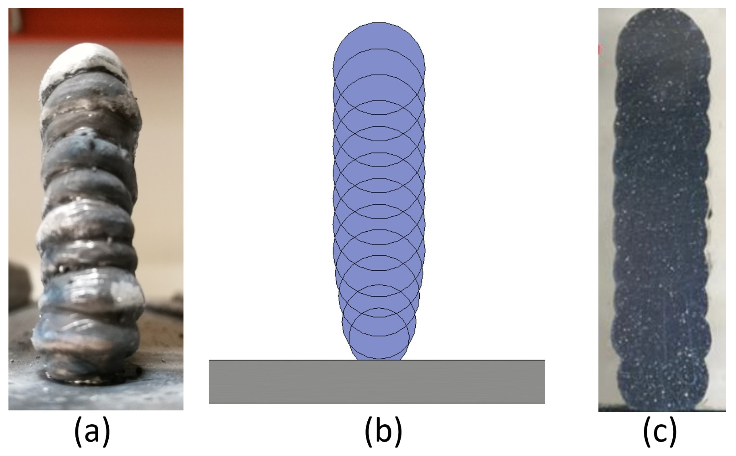
- A distance control system at the WAAM torch was programmed to control the ‘layers’ height. This system measures the distance between the torch and the last welded layer, comparing that input data with the theoretical distance of the printing simulation. If the measured data are within a predetermined scale, the procedure continues. Otherwise, the program skips a printing layer if the distance measured is smaller than the theoretical distance or repeats it if it is higher.
- The temperature sensor creates a second security loop, in which the last printing layer temperature is measured. This sensor is installed in the welding head, 25 mm behind the welding torch, measuring the temperature of the weld bead immediately after its deposition. High layer temperatures lead to geometrical inconsistencies in the geometry, and if too low, lead to interlayer-adhesion problems. This second low-temperature issue is less common and problematic. Thus, a minimum time between layers was used to ensure a layer temperature lower than 250 °C, even if geometrical singularities distort the temperature signal.
2.1. Case Study
2.1.1. Tooling Differences
- Only a final design CAD is needed.
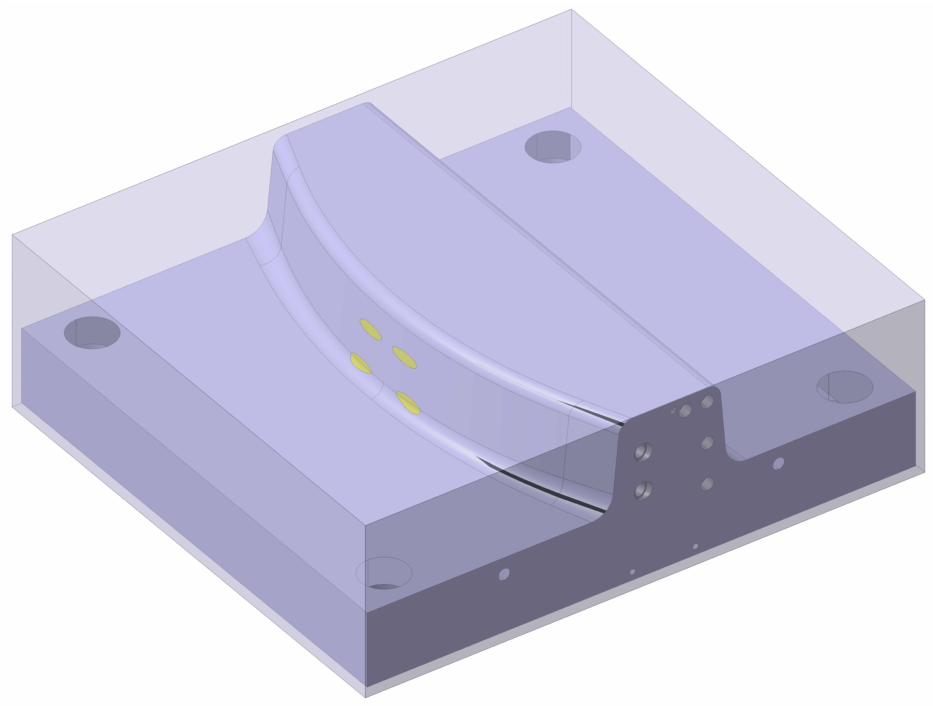
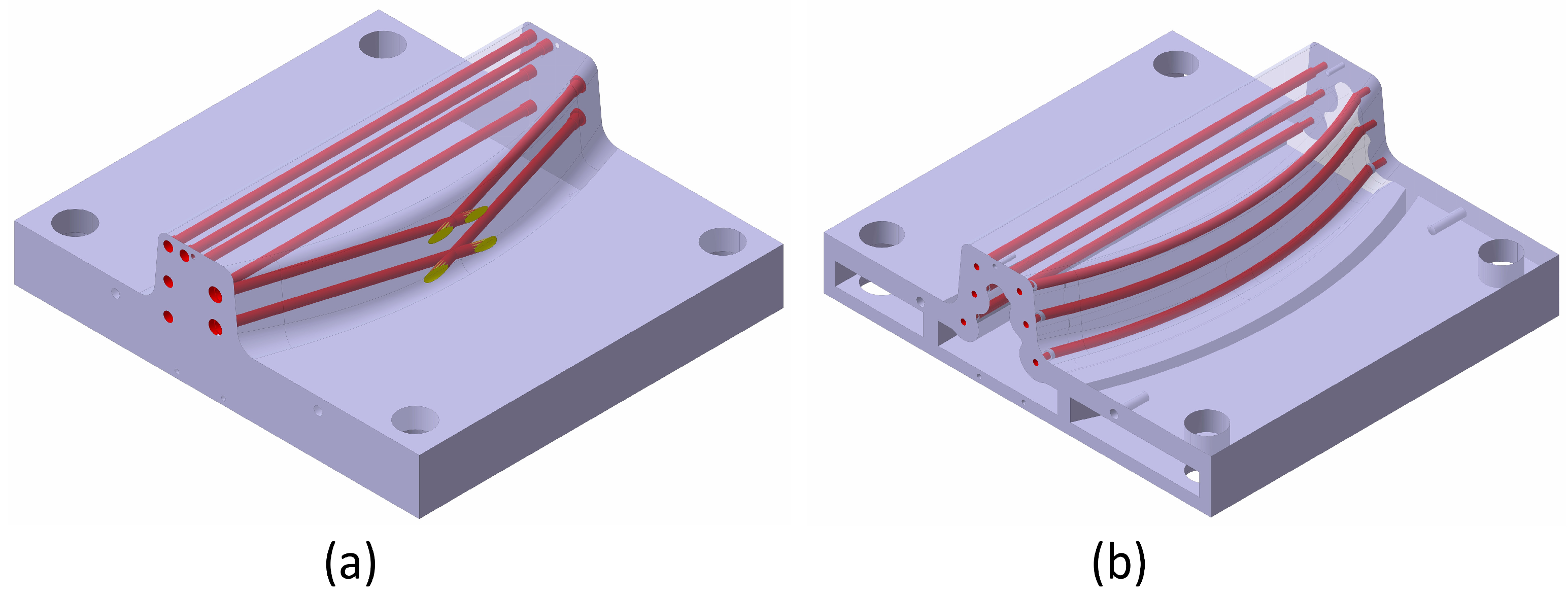
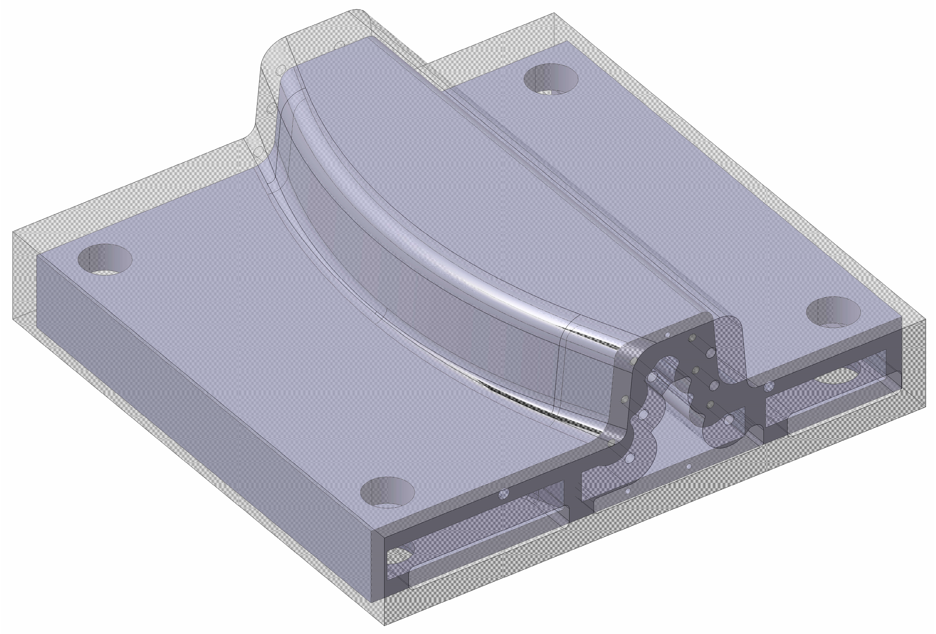
- The internal channels can only be designed straight due to machining limitations. For this reason, they cannot be adapted to the final shape of the tooling. These drills are designed straight through the tooling and drilled in a step before finishing.
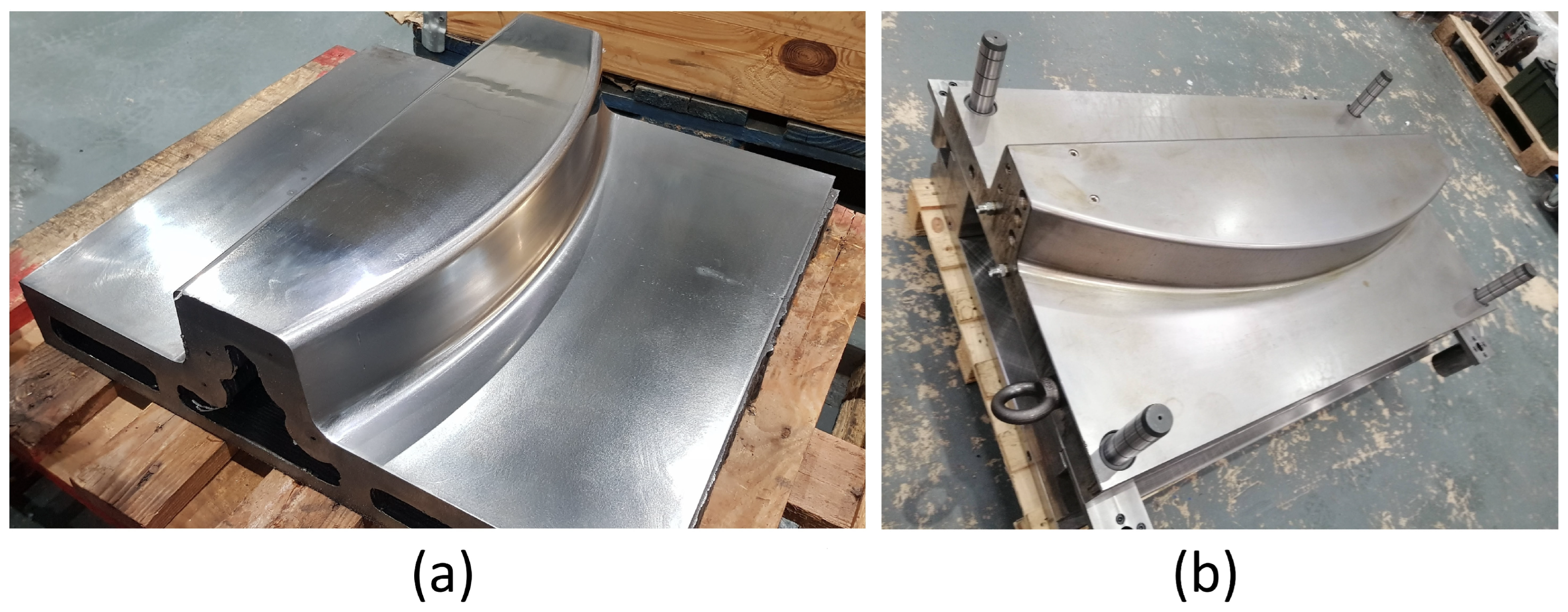
- In an extra process, these drills are subsequently plugged (manually) and re-machined, as shown in Figure 5.
- All construction singularities (threaded holes, reference holes, and holes for guideways) are performed during the same procedure.
- Due to machining area limitations, the inner tooling part is not emptied, as in WAAM tooling.
- Any construction singularity, such as screw drills located on surfaces perpendicular to the growth direction, is eliminated during the WAAM design and machined in the posterior hybrid-machining process.
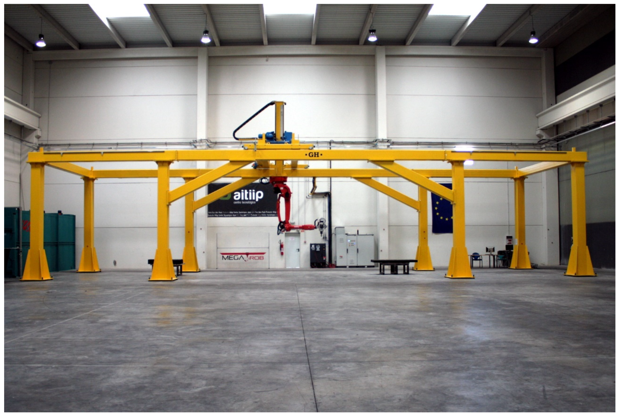
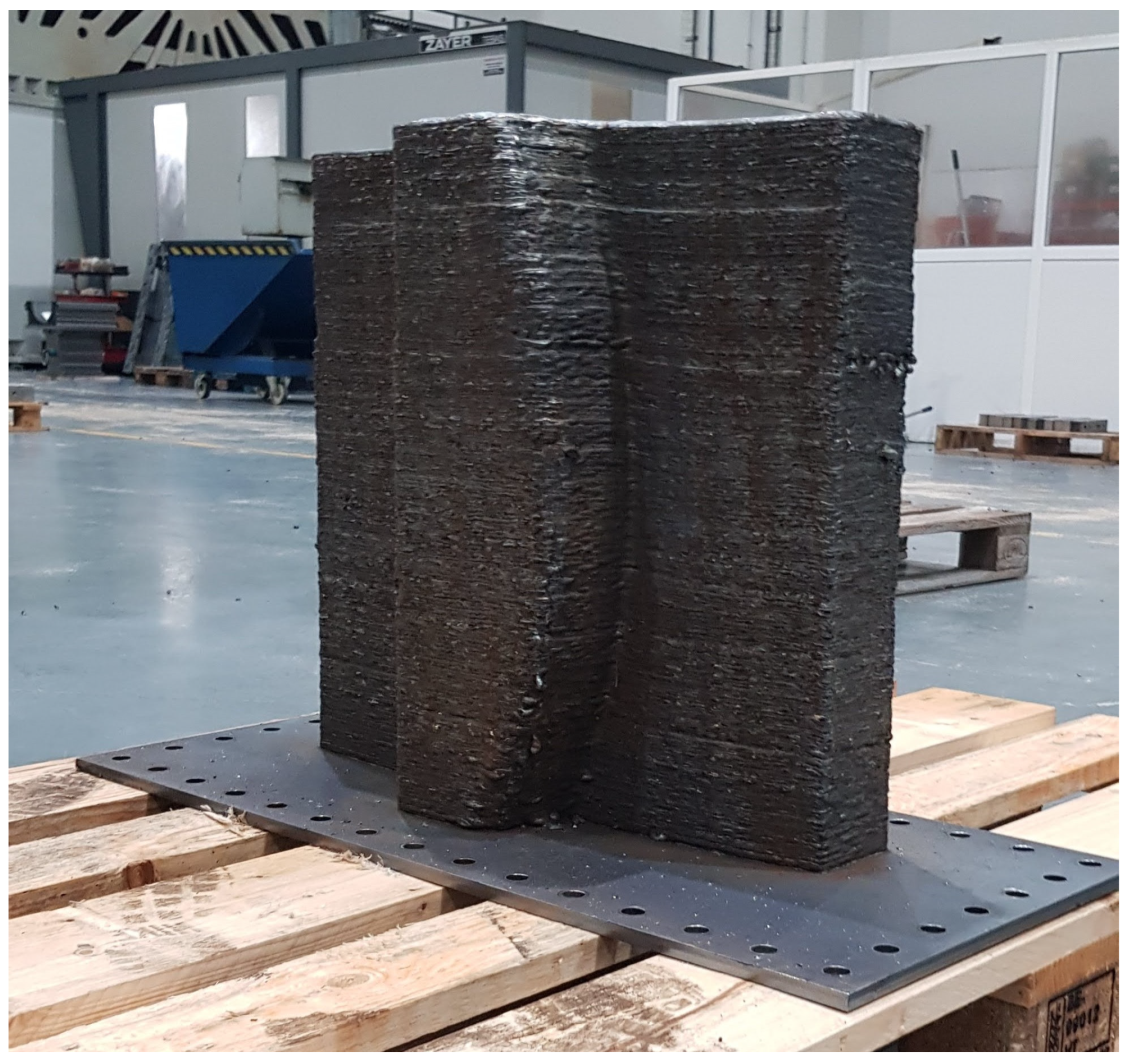
- The main tooling is constructed over a metallic plate larger than the tooling used as a printing base. When the WAAM process starts, extra layers are constructed over the plate and eliminated in the hybrid machining procedure, as shown in Figure 6.
- This figure also displays the printing direction, which is perpendicular to the theoretical base of the mould. This arrangement allows us to cast the inside of the part.
- As highlighted in Figure 5, the final tooling has internal heating channels. These channels follow the curved surface of the final thermoplastic part, homogenising the temperature distribution in the mould and increasing its heating rate.
- The design respects the restriction of a growth angle smaller than 20° relative to its horizontal plane.
- The printing process allows the tooling inner part to be designed as empty (design supported by FEM analysis).
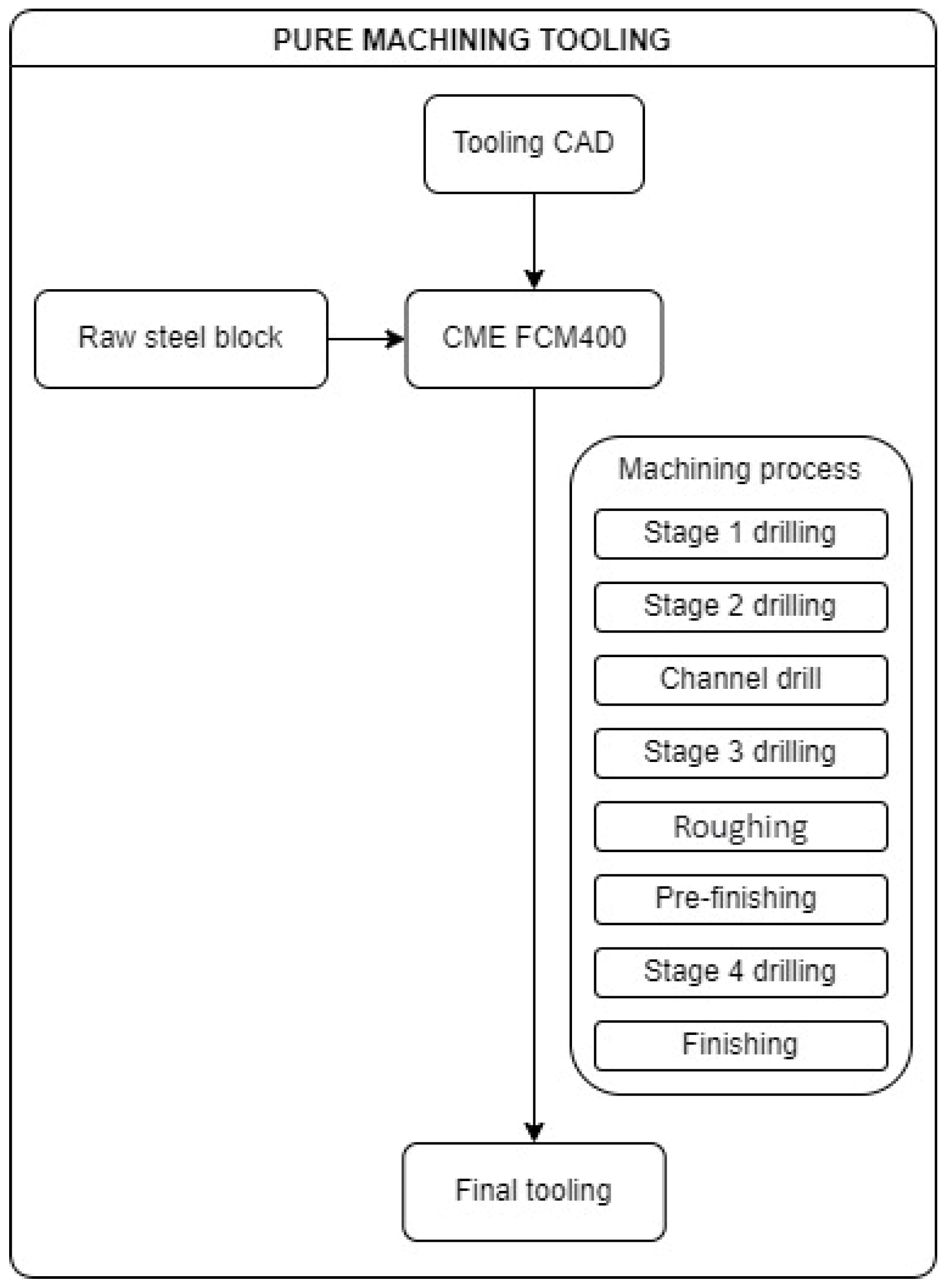
2.1.2. Pure Machining Tooling
- First, a drilling process was carried out before the roughing process, creating through-holes that pass through the workpiece.
- Then, rough milling of the area was carried out, approximating its geometry to the final geometry.
- Afterwards, a re-tapping procedure was conducted to blind these through holes, creating the internal heating circuit.
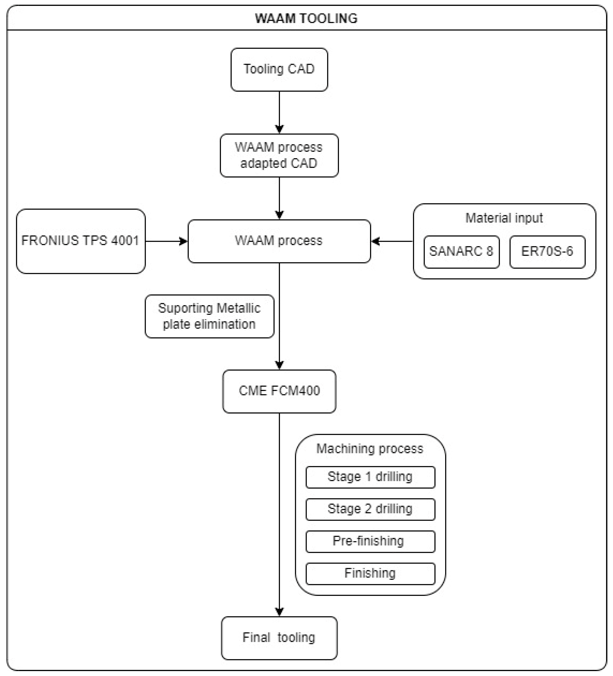
2.1.3. WAAM Tooling
- Over the aforementioned metallic plate, five extra layers of the inferior final figure were printed. This strategy assures the orthogonality of the final construction and creates an extra height that ensures the ease of plate removal.
- Based on the Figure 8 cutting, the WAAM strategy was the following for each layer:
- First, the contour of the tooling was printed.
- In the second stage, the contour of the inner channels was printed.
- Subsequently, the inner part was fulfilled following Figure 8’s pattern, ending the layer.
- The next layer started on a randomly selected point of the contour, avoiding, in this way, heat concentrations in specific areas.
- The WAAM process input data are provided in Table 1.
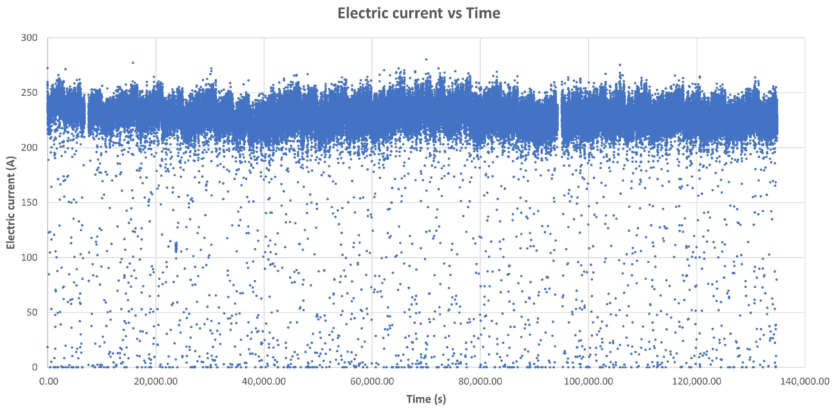
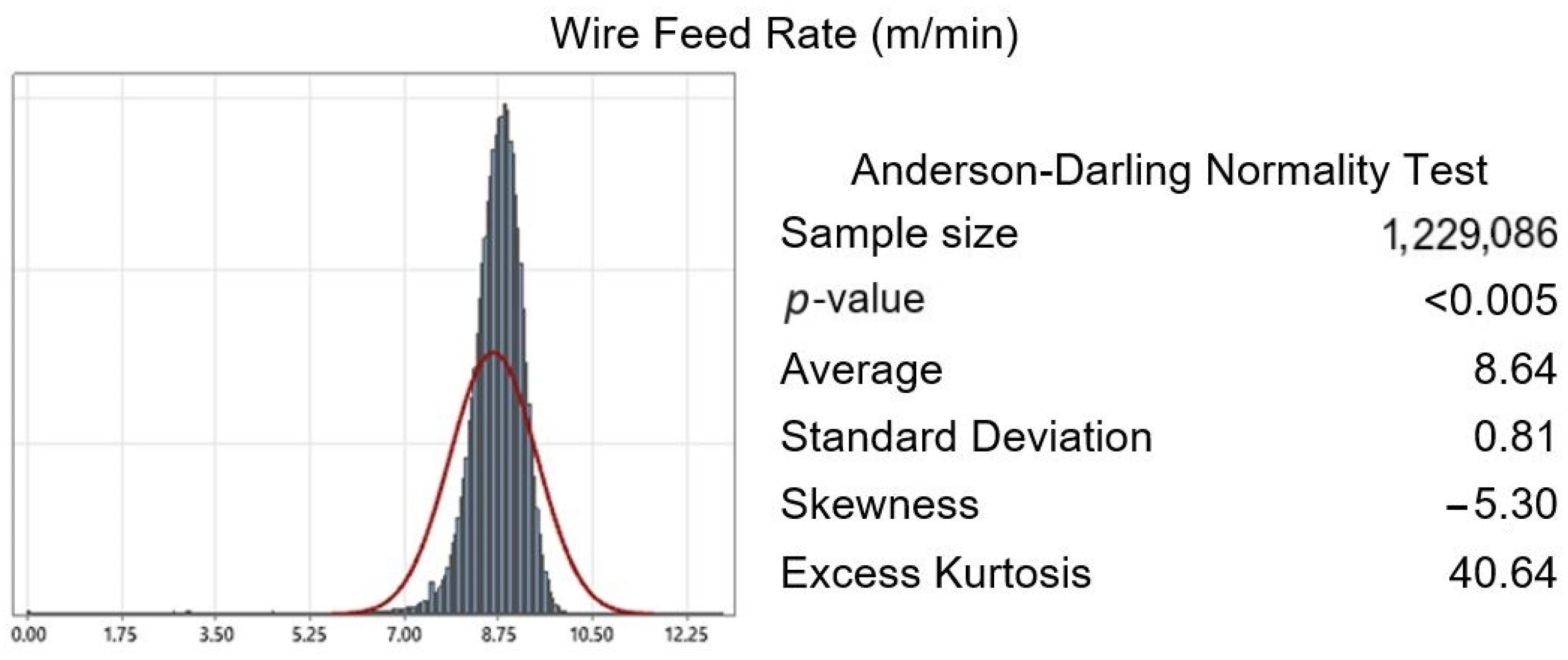
- The WFR is variable and adaptable to the geometry, printing route, and weld specifications. Its main value is also shown in Table 1.
3. Results
3.1. Pure Machining Tooling
3.1.1. Energy Consumption
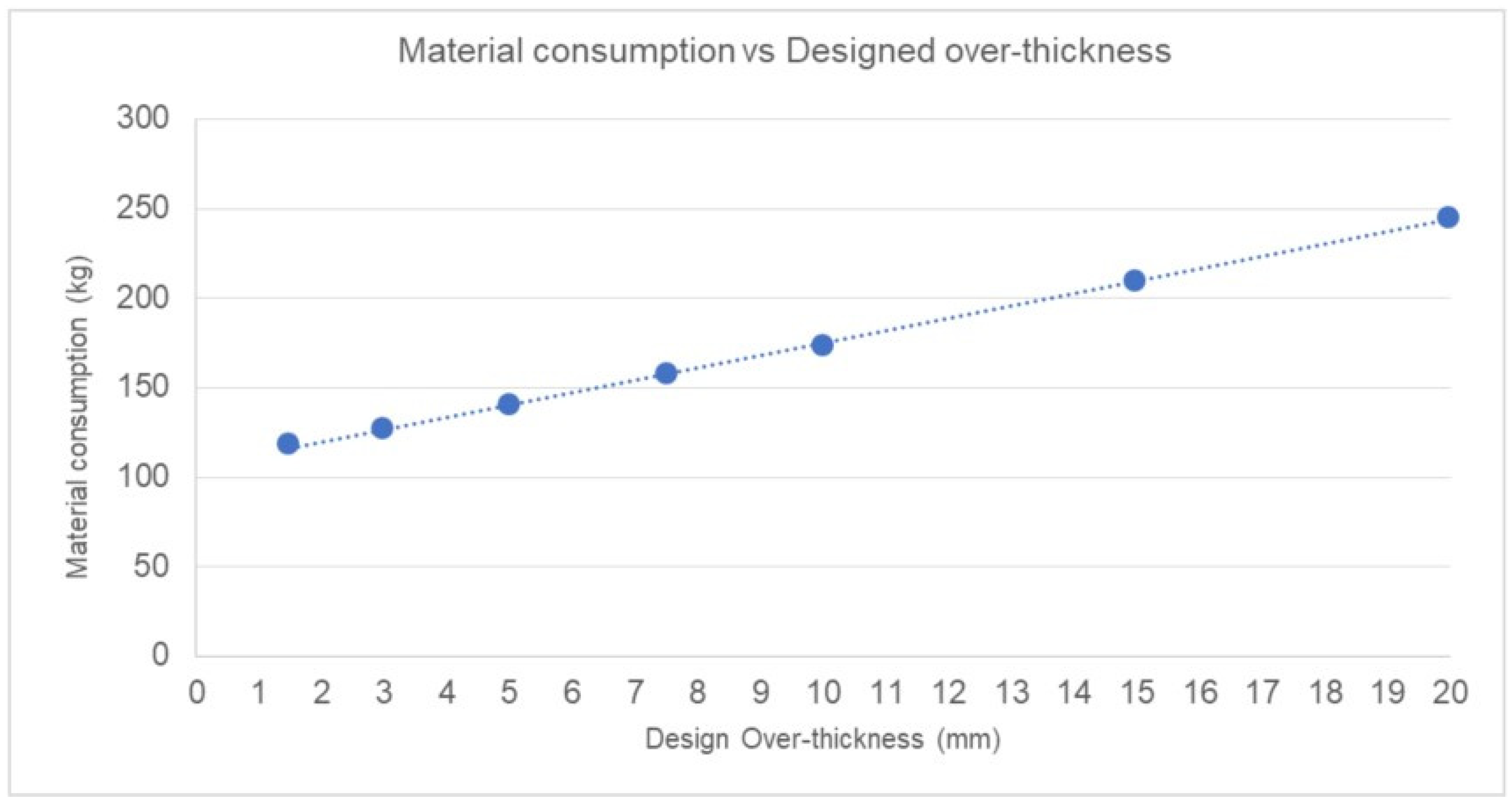
3.1.2. Material Consumption
- The material consumed weight.
- The final tooling weight.

| Pure Machining Tooling | |
|---|---|
| Material consumed weight | 291.345 kg |
| Final tooling weight | 152.747 kg |
| Material discarded | 47.57% |
3.2. WAAM Tooling
3.2.1. Energy Consumption
- The programming robot travelling between welding cordons.
- The programming robot travelling between layers.
- Not programming stops due to welding material replacement (wire or gas).
3.2.2. Material Consumption
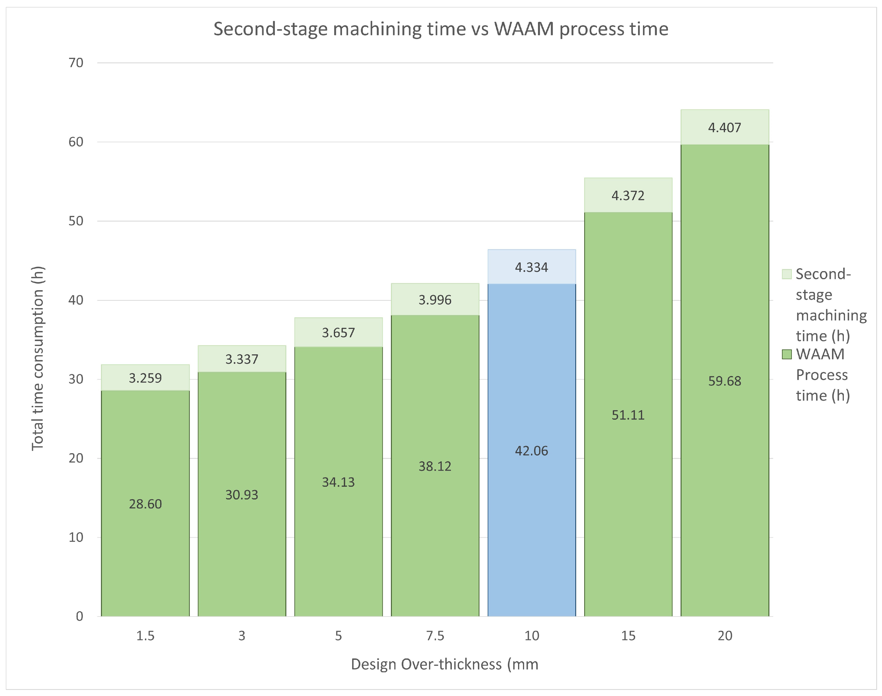
3.3. Sensitivity Analysis of the WAAM Over-Thickness
3.3.1. Theoretical Energy Input
3.3.2. Theoretical Energy Input
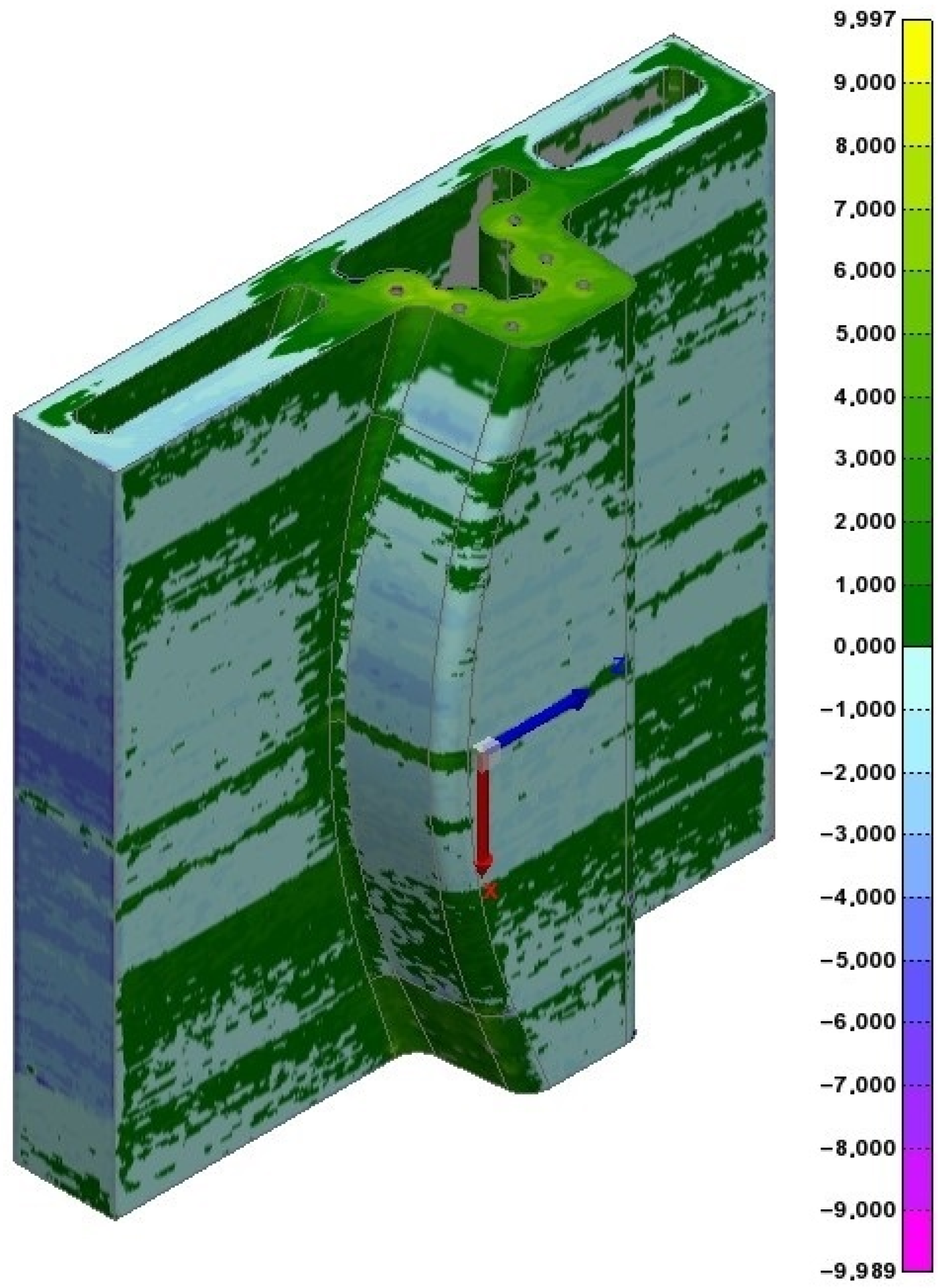
3.3.3. WAAM Tooling Metrology
4. Discussion
5. Conclusions
Author Contributions
Funding
Institutional Review Board Statement
Informed Consent Statement
Data Availability Statement
Conflicts of Interest
Appendix A


References
- Melnychuk, O.; Rachner, J.; Kaven, L.; Göppert, A.; Schmitt, R.H.; Tolio, T. Evaluation of Material Shortage Effect on Assembly Systems Considering Flexibility Levels. Procedia CIRP 2022, 107, 966–971. [Google Scholar] [CrossRef]
- Carvalho, H.; Naghshineh, B.; Govindan, K.; Cruz-Machado, V. The Resilience of On-Time Delivery to Capacity and Material Shortages: An Empirical Investigation in the Automotive Supply Chain. Comput. Ind. Eng. 2022, 171, 108375. [Google Scholar] [CrossRef]
- Jadhav, A.; Jadhav, V.S. A Review on 3D Printing: An Additive Manufacturing Technology. Mater. Today Proc. 2022, 62, 2094–2099. [Google Scholar] [CrossRef]
- Kannan, D.; Shankar, K.M.; Gholipour, P. Paving the Way for a Green Transition through Mitigation of Green Manufacturing Challenges: A Systematic Literature Review. J. Clean. Prod. 2022, 368, 132578. [Google Scholar] [CrossRef]
- Sharma, K.; Arora, R.; Nangia, R.; Singel, R.; Dharmveer; Dixit, S. Effects of Green Manufacturing and Technological Innovations on Sustainable Development. Mater. Today Proc. 2022, 69, 266–270. [Google Scholar] [CrossRef]
- Prakash, A.; Arora, M.; Mittal, A.; Kampani, S.; Dixit, S. Green Manufacturing: Related Literature over the Past Decade. Mater. Today Proc. 2022, 69, 468–472. [Google Scholar] [CrossRef]
- Ahn, D.-G. Direct Metal Additive Manufacturing Processes and Their Sustainable Applications for Green Technology: A Review. Int. J. Precis. Eng. Manuf.—Green Technol. 2016, 3, 381–395. [Google Scholar] [CrossRef]
- Roberts, T.; Bartkova, B. Additive Manufacturing Trend Report 2021: 3D Printing Market Growth in the Year of the COVID-19; Hubs BV: Amsterdam, The Netherlands, 2021; pp. 1–16. [Google Scholar]
- Derekar, K.S. A Review of Wire Arc Additive Manufacturing and Advances in Wire Arc Additive Manufacturing of Aluminium. Mater. Sci. Technol. 2018, 34, 895–916. [Google Scholar] [CrossRef]
- Paolini, A.; Kollmannsberger, S.; Rank, E. Additive Manufacturing in Construction: A Review on Processes, Applications, and Digital Planning Methods. Addit. Manuf. 2019, 30, 100894. [Google Scholar] [CrossRef]
- Singh, S.; Sharma, S.K.; Rathod, D.W. A Review on Process Planning Strategies and Challenges of WAAM. Mater. Today Proc. 2021, 47, 6564–6575. [Google Scholar] [CrossRef]
- Betzler, B.R. Additive Manufacturing in the Nuclear Reactor Industry. Encycl. Nucl. Energy 2021, 1, 851–863. [Google Scholar] [CrossRef]
- Li, Y.; Wu, S.; Wang, J.; Wang, H.; Kong, W.; Cheng, F. Microstructure Homogeneity and Strength-Toughness Balance in Submerged Arc Additive Manufactured Mn-Ni-Mo High-Strength Steel by Unique Intrinsic Heat Treatment. J. Mater. Process. Technol. 2022, 307, 117682. [Google Scholar] [CrossRef]
- Evans, S.I.; Wang, J.; Qin, J.; He, Y.; Shepherd, P.; Ding, J. A Review of WAAM for Steel Construction—Manufacturing, Material and Geometric Properties, Design, and Future Directions. Structures 2022, 44, 1506–1522. [Google Scholar] [CrossRef]
- Zhang, J.; Zhao, T.; Yi, Y.; An, Q.; Yanagimoto, J. Additive Manufacturing Assisted Fabrication of Octet Truss Structures Using Continuous Carbon Fibre Composites and the Resulting Mechanical Responses. J. Mater. Process. Technol. 2023, 319, 118089. [Google Scholar] [CrossRef]
- Toth, A.D.; Padayachee, J.; Mahlatji, T.; Vilakazi, S. Report on Case Studies of Additive Manufacturing in the South African Railway Industry. Sci. Afr. 2022, 16, e01219. [Google Scholar] [CrossRef]
- Busachi, A.; Erkoyuncu, J.; Colegrove, P.; Martina, F.; Ding, J. Designing a WAAM Based Manufacturing System for Defence Applications. Procedia CIRP 2015, 37, 48–53. [Google Scholar] [CrossRef]
- Anand, M.; Bishwakarma, H.; Kumar, N.; Ujjwal, K.; Das, A.K. Fabrication of Multilayer Thin Wall by WAAM Technique and Investigation of Its Microstructure and Mechanical Properties. Mater. Today Proc. 2022, 56, 927–930. [Google Scholar] [CrossRef]
- Al-Nabulsi, Z.; Mottram, J.T.; Gillie, M.; Kourra, N.; Williams, M.A. Mechanical and X Ray Computed Tomography Characterisation of a WAAM 3D Printed Steel Plate for Structural Engineering Applications. Constr. Build. Mater. 2021, 274, 121700. [Google Scholar] [CrossRef]
- Vora, J.; Parmar, H.; Chaudhari, R.; Khanna, S.; Doshi, M.; Patel, V. Experimental Investigations on Mechanical Properties of Multi-Layered Structure Fabricated by GMAW-Based WAAM of SS316L. J. Mater. Res. Technol. 2022, 20, 2748–2757. [Google Scholar] [CrossRef]
- Su, G.; Shi, Y.; Li, G.; Zhang, G.; Xu, Y. Improving the Deposition Efficiency and Mechanical Properties of Additive Manufactured Inconel 625 through Hot Wire Laser Metal Deposition. J. Mater. Process. Technol. 2023, 322, 118175. [Google Scholar] [CrossRef]
- Jackson, M.A.; Van Asten, A.; Morrow, J.D.; Min, S.; Pfefferkorn, F.E. A Comparison of Energy Consumption in Wire-Based and Powder-Based Additive-Subtractive Manufacturing. Procedia Manuf. 2016, 5, 989–1005. [Google Scholar] [CrossRef]
- Singh, S.R.; Khanna, P. Wire Arc Additive Manufacturing (WAAM): A New Process to Shape Engineering Materials. Mater. Today Proceed. 2021, 44, 118–128. [Google Scholar] [CrossRef]
- Martina, F.; Mehnen, J.; Williams, S.W.; Colegrove, P.; Wang, F. Investigation of the Benefits of Plasma Deposition for the Additive Layer Manufacture of Ti-6Al-4V. J. Mater. Process. Technol. 2012, 212, 1377–1386. [Google Scholar] [CrossRef]
- Roschli, A.; Gaul, K.T.; Boulger, A.M.; Post, B.K.; Chesser, P.C.; Love, L.J.; Blue, F.; Borish, M. Designing for Big Area Additive Manufacturing. Addit. Manuf. 2019, 25, 275–285. [Google Scholar] [CrossRef]
- Brackett, J.; Yan, Y.; Cauthen, D.; Kishore, V.; Lindahl, J.; Smith, T.; Sudbury, Z.; Ning, H.; Kunc, V.; Duty, C. Characterizing Material Transitions in Large-Scale Additive Manufacturing. Addit. Manuf. 2021, 38, 101750. [Google Scholar] [CrossRef]
- Kampker, A.; Triebs, J.; Kawollek, S.; Ayvaz, P.; Hohenstein, S. Review on Machine Designs of Material Extrusion Based Additive Manufacturing (AM) Systems—Status-Quo and Potential Analysis for Future AM Systems. Procedia CIRP 2019, 81, 815–819. [Google Scholar] [CrossRef]
- Robles Poblete, F.; Ireland, M.; Slattery, L.; Davids, W.G.; Lopez-Anido, R.A. In Situ, Real-Time Temperature Mapping and Thermal FE Simulations of Large-Format 3D Printed PETG/CF Vertical Wall. Materials 2023, 16, 6486. [Google Scholar] [CrossRef] [PubMed]
- Paranthaman, M.P.; Yildirim, V.; Lamichhane, T.N.; Begley, B.A.; Post, B.K.; Hassen, A.A.; Sales, B.C.; Gandha, K.; Nlebedim, I.C. Additive Manufacturing of Isotropic NdFeB PPS Bonded Permanent Magnets. Materials 2020, 13, 3319. [Google Scholar] [CrossRef]
- Kawalkar, R.; Dubey, H.K.; Lokhande, S.P. Wire Arc Additive Manufacturing: A Brief Review on Advancements in Addressing Industrial Challenges Incurred with Processing Metallic Alloys. Mater. Today Proc. 2022, 50, 1971–1978. [Google Scholar] [CrossRef]
- Nurhudan, A.I.; Supriadi, S.; Whulanza, Y.; Saragih, A.S. Additive Manufacturing of Metallic Based on Extrusion Process: A Review. J. Manuf. Process. 2021, 66, 228–237. [Google Scholar] [CrossRef]
- Clare, A.T.; Mishra, R.S.; Merklein, M.; Tan, H.; Todd, I.; Chechik, L.; Li, J.; Bambach, M. Alloy Design and Adaptation for Additive Manufacture. J. Mater. Process. Technol. 2022, 299, 117358. [Google Scholar] [CrossRef]
- Sun, J.; Ye, D.; Zou, J.; Chen, X.; Wang, Y.; Yuan, J.; Liang, H.; Qu, H.; Binner, J.; Bai, J. A Review on Additive Manufacturing of Ceramic Matrix Composites. J. Mater. Sci. Technol. 2023, 138, 1–16. [Google Scholar] [CrossRef]
- Li, J.; Durandet, Y.; Huang, X.; Sun, G.; Ruan, D. Additively Manufactured Fiber-Reinforced Composites: A Review of Mechanical Behavior and Opportunities. J. Mater. Sci. Technol. 2022, 119, 219–244. [Google Scholar] [CrossRef]
- Riquelme, A.; Sánchez de Rojas Candela, C.; Rodrigo, P.; Rams, J. Influence of Process Parameters in Additive Manufacturing of Highly Reinforced 316L/SiCp Composites. J. Mater. Process. Technol. 2022, 299, 117325. [Google Scholar] [CrossRef]
- Gregor-Svetec, D.; Leskovšek, M.; Vrabič Brodnjak, U.; Stankovič Elesini, U.; Muck, D.; Urbas, R. Characteristics of HDPE/Cardboard Dust 3D Printable Composite Filaments. J. Mater. Process. Technol. 2020, 276, 116379. [Google Scholar] [CrossRef]
- Cacace, S.; Furlan, V.; Sorci, R.; Semeraro, Q.; Boccadoro, M. Using Recycled Material to Produce Gas-Atomized Metal Powders for Additive Manufacturing Processes. J. Clean. Prod. 2020, 268, 122218. [Google Scholar] [CrossRef]
- Hart, K.R.; Frketic, J.B.; Brown, J.R. Recycling Meal-Ready-to-Eat (MRE) Pouches into Polymer Filament for Material Extrusion Additive Manufacturing. Addit. Manuf. 2018, 21, 536–543. [Google Scholar] [CrossRef]
- Dritsas, S.; Fernandez, J.G. Towards Sustainable Additive Manufacturing Using Fungus-like Adhesive Materials. Mater. Today Proc. 2022, 70, 418–424. [Google Scholar] [CrossRef]
- Ren, L.; Wang, Z.; Ren, L.; Han, Z.; Liu, Q.; Song, Z. Graded Biological Materials and Additive Manufacturing Technologies for Producing Bioinspired Graded Materials: An Overview. Compos. Part B Eng. 2022, 242, 110086. [Google Scholar] [CrossRef]
- ASTM ISO/ASTM52900-15; Standard Terminology for Additive Manufacturing—General Principles—Terminology. ASTM International: West Conshohocken, PA, USA, 2015.
- Ahn, D.-G. Directed Energy Deposition (DED) Process: State of the Art. Int. J. Precis. Eng. Manuf.-Green Technol. 2021, 8, 703–742. [Google Scholar] [CrossRef]
- Chaturvedi, M.; Scutelnicu, E.; Rusu, C.C.; Mistodie, L.R.; Mihailescu, D.; Vendan, S.A. Wire Arc Additive Manufacturing: Review on Recent Findings and Challenges in Industrial Applications and Materials Characterization. Metals 2021, 11, 939. [Google Scholar] [CrossRef]
- Rodríguez-González, P.; Ruiz-Navas, E.M.; Gordo, E. Wire Arc Additive Manufacturing (WAAM) for Aluminum-Lithium Alloys: A Review. Materials 2023, 16, 1375. [Google Scholar] [CrossRef] [PubMed]
- Jiang, D.; Ning, F. Physical-Mechanical Behaviors of Stainless Steel Plate-Lattice Built by Material Extrusion Additive Manufacturing. J. Mater. Process. Technol. 2022, 309, 117739. [Google Scholar] [CrossRef]
- Li, Y.; Han, Q.; Horváth, I.; Zhang, G. Repairing Surface Defects of Metal Parts by Groove Machining and Wire + Arc Based Filling. J. Mater. Process. Technol. 2019, 274, 116268. [Google Scholar] [CrossRef]
- Liu, W.; Deng, K.; Wei, H.; Zhao, P.; Li, J.; Zhang, Y. A Decision-Making Model for Comparing the Energy Demand of Additive-Subtractive Hybrid Manufacturing and Conventional Subtractive Manufacturing Based on Life Cycle Method. J. Clean. Prod. 2021, 311, 127795. [Google Scholar] [CrossRef]
- Priarone, P.C.; Ingarao, G. Towards Criteria for Sustainable Process Selection: On the Modelling of Pure Subtractive versus Additive/Subtractive Integrated Manufacturing Approaches. J. Clean. Prod. 2017, 144, 57–68. [Google Scholar] [CrossRef]
- Lu, X.; Li, M.V.; Yang, H. Comparison of Wire-Arc and Powder-Laser Additive Manufacturing for IN718 Superalloy: Unified Consideration for Selecting Process Parameters Based on Volumetric Energy Density. Int. J. Adv. Manuf. Technol. 2021, 114, 1517–1531. [Google Scholar] [CrossRef]
- Campatelli, G.; Montevecchi, F.; Venturini, G.; Ingarao, G.; Priarone, P.C. Integrated WAAM-Subtractive Versus Pure Subtractive Manufacturing Approaches: An Energy Efficiency Comparison. Int. J. Precis. Eng. Manuf.-Green Technol. 2020, 7, 1–11. [Google Scholar] [CrossRef]
- Tanabi, N.; Silva, A.M.; Pessoa, M.A.O.; Tsuzuki, M.S.G. Robust Algorithm Software for NACA 4-Digit Airfoil Shape Optimization Using the Adjoint Method. Appl. Sci. 2023, 13, 4269. [Google Scholar] [CrossRef]
- González, J.; Rodríguez, I.; Prado-Cerqueira, J.L.; Diéguez, J.L.; Pereira, A. Additive Manufacturing with GMAW Welding and CMT Technology. Procedia Manuf. 2017, 13, 840–847. [Google Scholar] [CrossRef]
- Ramarao, M.; King, M.F.L.; Sivakumar, A.; Manikandan, V.; Vijayakumar, M.; Subbiah, R. Optimizing GMAW Parameters to Achieve High Impact Strength of the Dissimilar Weld Joints Using Taguchi Approach. Mater. Today Proc. 2022, 50, 861–866. [Google Scholar] [CrossRef]
- Ding, J.; Colegrove, P.; Martina, F.; Williams, S.; Wiktorowicz, R.; Palt, M.R. Development of a Laminar Flow Local Shielding Device for Wire + Arc Additive Manufacture. J. Mater. Process. Technol. 2015, 226, 99–105. [Google Scholar] [CrossRef]
- Wang, Z.; Zimmer-Chevret, S.; Léonard, F.; Abba, G. Improvement Strategy for the Geometric Accuracy of Bead’s Beginning and End Parts in Wire-Arc Additive Manufacturing (WAAM). Int. J. Adv. Manuf. Technol. 2022, 118, 2139–2151. [Google Scholar] [CrossRef]
- Xiong, J.; Li, Y.; Li, R.; Yin, Z. Influences of Process Parameters on Surface Roughness of Multi-Layer Single-Pass Thin-Walled Parts in GMAW-Based Additive Manufacturing. J. Mater. Process. Technol. 2018, 252, 128–136. [Google Scholar] [CrossRef]
- Williams, S.; Martina, F.; Wood, D.; Colomo, A.G. A Comparison Framework to Support the Selection of the Best Additive Manufacturing Process for Specific Aerospace Applications. Int. J. Rapid Manuf. 2020, 9, 194–211. [Google Scholar] [CrossRef]
- Liu, Z.Y.; Li, C.; Fang, X.Y.; Guo, Y.B. Energy Consumption in Additive Manufacturing of Metal Parts. Procedia Manuf. 2018, 26, 834–845. [Google Scholar] [CrossRef]
- Campatelli, G.; Campanella, D.; Barcellona, A.; Fratini, L.; Grossi, N.; Ingarao, G. Microstructural, Mechanical and Energy Demand Characterization of Alternative WAAM Techniques for Al-Alloy Parts Production. CIRP J. Manuf. Sci. Technol. 2020, 31, 492–499. [Google Scholar] [CrossRef]
- Warsi, R.; Kazmi, K.H.; Chandra, M. Mechanical Properties of Wire and Arc Additive Manufactured Component Deposited by a CNC Controlled GMAW. Mater. Today Proc. 2022, 56, 2818–2825. [Google Scholar] [CrossRef]
- Chernovol, N.; Sharma, A.; Tjahjowidodo, T.; Lauwers, B.; Rymenant, P. Van Machinability of Wire and Arc Additive Manufactured Components. CIRP J. Manuf. Sci. Technol. 2021, 35, 379–389. [Google Scholar] [CrossRef]
- Bociaga, E. Effect of Mould Temperature and Injection Speed on Selected Properties of Polyethylene Mouldings. Int. Polym. Sci. Technol. 2001, 28, 96–102. [Google Scholar] [CrossRef]
- Lopes, J.G.; Machado, C.M.; Duarte, V.R.; Rodrigues, T.A.; Santos, T.G.; Oliveira, J.P. Effect of Milling Parameters on HSLA Steel Parts Produced by Wire and Arc Additive Manufacturing (WAAM). J. Manuf. Process. 2020, 59, 739–749. [Google Scholar] [CrossRef]
- Dinovitzer, M.; Chen, X.; Laliberte, J.; Huang, X.; Frei, H. Effect of Wire and Arc Additive Manufacturing (WAAM) Process Parameters on Bead Geometry and Microstructure. Addit. Manuf. 2019, 26, 138–146. [Google Scholar] [CrossRef]
- Nagasai, B.P.; Malarvizhi, S.; Balasubramanian, V. Effect of Welding Processes on Mechanical and Metallurgical Characteristics of Carbon Steel Cylindrical Components Made by Wire Arc Additive Manufacturing (WAAM) Technique. CIRP J. Manuf. Sci. Technol. 2022, 36, 100–116. [Google Scholar] [CrossRef]
- Zhang, C.; Shen, C.; Hua, X.; Li, F.; Zhang, Y.; Zhu, Y. Influence of Wire-Arc Additive Manufacturing Path Planning Strategy on the Residual Stress Status in One Single Buildup Layer. Int. J. Adv. Manuf. Technol. 2020, 111, 797–806. [Google Scholar] [CrossRef]
- Wang, X.; Wang, A.; Li, Y. A Sequential Path-Planning Methodology for Wire and Arc Additive Manufacturing Based on a Water-Pouring Rule. Int. J. Adv. Manuf. Technol. 2019, 103, 3813–3830. [Google Scholar] [CrossRef]
- Chen, X.; Kong, F.; Fu, Y.; Zhao, X.; Li, R.; Wang, G.; Zhang, H. A Review on Wire-Arc Additive Manufacturing: Typical Defects, Detection Approaches, and Multisensor Data Fusion-Based Model. Int. J. Adv. Manuf. Technol. 2021, 117, 707–727. [Google Scholar] [CrossRef]
- Thien, A.; Saldana, C.; Kurfess, T. The Effect of WAAM Process Parameters on Process Conditions and Production Metrics in the Fabrication of Single-Pass Multi-Layer Wall Artifacts. Int. J. Adv. Manuf. Technol. 2022, 119, 531–547. [Google Scholar] [CrossRef]
- Zhang, H.; Liu, W.; Zhao, X.; Zhang, X.; Chen, C. Improvement in Microstructure and Properties of 304 Steel Wire Arc Additive Manufacturing by the Micro-Control Deposition Trajectory. Materials 2024, 17, 1170. [Google Scholar] [CrossRef]
- Garaigordobil, A.; Ansola, R.; Veguería, E.; Fernandez, I. Overhang Constraint for Topology Optimization of Self-Supported Compliant Mechanisms Considering Additive Manufacturing. CAD Comput. Aided Des. 2019, 109, 33–48. [Google Scholar] [CrossRef]
- Doubrovski, Z.; Verlinden, J.C.; Geraedts, J.M.P. Optimal Design for Additive Manufacturing: Opportunities and Challenges. In Volume 9: 23rd International Conference on Design Theory and Methodology; 16th Design for Manufacturing and the Life Cycle Conference; ASMEDC, Proceedings of the 23rd International Conference on Design Theory and Methodology, Washington, DC, USA, 28–31 August 2011; ASME: New York, NY, USA, 2011; pp. 635–646. [Google Scholar]
- Zhang, J.; Cao, Q.; Lu, W.F. A Review on Design and Removal of Support Structures in Metal Additive Manufacturing. Mater. Today Proc. 2022, 70, 407–411. [Google Scholar] [CrossRef]
- Li, Y.; Huang, X.; Horváth, I.; Zhang, G. GMAW-Based Additive Manufacturing of Inclined Multi-Layer Multi-Bead Parts with Flat-Position Deposition. J. Mater. Process. Technol. 2018, 262, 359–371. [Google Scholar] [CrossRef]
- Xu, T.; Cui, Y.; Ma, S.; Wang, J.; Liu, C. Exploring the Inclined Angle Limit of Fabricating Unsupported Rods Structures by Pulse Hot-Wire Arc Additive Manufacturing. J. Mater. Process. Technol. 2021, 295, 117160. [Google Scholar] [CrossRef]
- Liu, B.; Shen, H.; Zhou, Z.; Jin, J.; Fu, J. Research on Support-Free WAAM Based on Surface/Interior Separation and Surface Segmentation. J. Mater. Process. Technol. 2021, 297, 117240. [Google Scholar] [CrossRef]
- Circutor Circutor C-80 System Analyser. Balanced Three-Phase Portable Power Analyzer 2005. Available online: https://circutor.com/productos/analizadores-de-redes-portatiles/analizadores-de-red-portatiles/analizador-de-redes-portatil-monofasico-o-trifasico-equilibrado/product/M80120./ (accessed on 8 June 2024).
- AITIIP FUNDATION. Hybrid Automated Machine Integrating Concurrent Manufacturing Processes, Increasing the Production Volume of Functional on-Demand Using High Multi-Material Deposition Rates Fact Sheet Project Information 2019. Available online: https://cordis.europa.eu/project/id/723759/reporting (accessed on 8 June 2024).
- COMAU COMAU NJ130. 6-Axes Collaborative Robotic Arm 2010. Available online: https://www.comau.com/en/competencies/robotics-automation/robot-team/nj-130-2-0/ (accessed on 8 June 2024).
- Open Mind Technologies. HyperMILL CAD/CAM Software, (version 2023) Windows; Open Mind Technologies: Weßling, Germany, 2023.
- Ultimaker. UltiMaker Cura 2023, v. 5.6.0; Ultimaker: Utrecht, The Netherlands, 2023.
- Fronius Fronius TPS 400i. MIG/MAG Welding System 2018. Available online: https://www.fronius.com/es-es/spain/tecnologia-de-soldadura/productos/soldadura-manual/migmag/tpsi/tpsi/tps-400i (accessed on 8 June 2024).
- Keyence CMOS Multi-Function Analogue Laser Sensor. Laser Differentiation Displacement Sensor 2010. Available online: https://www.keyence.com/products/sensor/positioning/il/ (accessed on 8 June 2024).
- OPTRIS OPTRIS—3MH CF. Micro Size Infrared Thermometer for Precise Temperature Measurement of Metal from 50 to 600 °C 2018. Available online: https://www.optris.com/es/producto/termometros-infrarrojos/serie-ct/ct-3m/ (accessed on 8 June 2024).
- Fundacion Tekniker. Development of Thermoplastic Press-Forming Tool for Advanced Rear End Closing Frame Prototype and Tooling 4.0 for Assembly and Transportation of the Advanced Rear End Prototype 2022. Available online: https://cordis.europa.eu/project/id/886491 (accessed on 8 June 2024).
- Khalid, M.Y.; Arif, Z.U.; Rashid, A. Al Investigation of Tensile and Flexural Behavior of Green Composites along with Their Impact Response at Different Energies. Int. J. Precis. Eng. Manuf.-Green Technol. 2022, 9, 1399–1410. [Google Scholar] [CrossRef]
- Choi, J.Y.; Jeon, J.H.; Lyu, J.H.; Park, J.; Kim, G.Y.; Chey, S.Y.; Quan, Y.-J.; Bhandari, B.; Prusty, B.G.; Ahn, S.-H. Current Applications and Development of Composite Manufacturing Processes for Future Mobility. Int. J. Precis. Eng. Manuf.-Green Technol. 2022, 10, 269–291. [Google Scholar] [CrossRef]
- Li, X.-P.; Zhao, G.-Q.; Guan, Y.-J.; Ma, M.-X. Optimal Design of Heating Channels for Rapid Heating Cycle Injection Mold Based on Response Surface and Genetic Algorithm. Mater. Des. 2009, 30, 4317–4323. [Google Scholar] [CrossRef]
- HEXAGON Leica T-Scan 5 2015. Available online: https://hexagon.com/products/leica-t-scan-5 (accessed on 8 June 2024).
- ISO 14175:2008; Welding Consumables—Gases and Gas Mixtures for Fusion Welding and Allied Processes. International Organization for Standardization: Geneva, Switzerland, 2008.


| Process Parameters for WAAM Deposition | ||
|---|---|---|
| Process parameters | Details | Value |
| Speed | Welding speed | 0.02 m/s |
| Wire feed rate | 8.64 ± 0.81 m/min | |
| Deposition rate | 0.077 kg/min | |
| Distance and angle | Layer height | 1.2 mm |
| Electrode to layer angle | 90° | |
| Shield gas | Shield gas type | ISO 14175-M20-ArC-8 [90] (CO2 8% Ar 92%) |
| Shield gas flow rate | 15 L/min | |
| Energy Inputs | Average Power Consumption |
|---|---|
| Gantry crane | 1.890 kWh |
| Robotic arm | 0.440 kWh |
| General | 2.15 kWh |
| WAAM Process Deposition Power | |
|---|---|
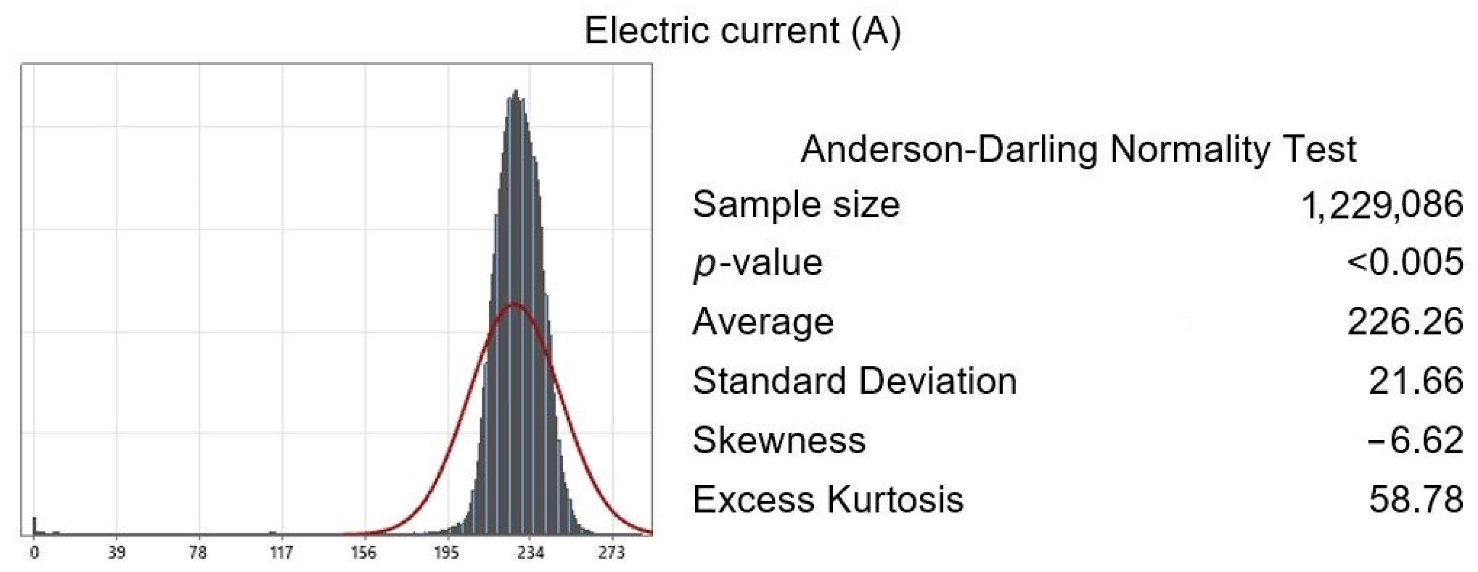
| Current | 226.26 ± 21.66 A |
| Arc voltage | 17.39 ± 0.97 V |
| Electric power | 3945.00 ± 377.36 W |
| Machining Process (kWh) | WAAM Process (kWh) | TOTAL (kWh) | |
|---|---|---|---|
| WAAM Tooling | 311.365 | 257.150 | 568.515 |
| WAAM Process Deposition Power | |
|---|---|
| Material consumed weight | 173.091 kg |
| Final tooling weight | 90.960 kg |
| Material discarded | 47.45% |
Disclaimer/Publisher’s Note: The statements, opinions and data contained in all publications are solely those of the individual author(s) and contributor(s) and not of MDPI and/or the editor(s). MDPI and/or the editor(s) disclaim responsibility for any injury to people or property resulting from any ideas, methods, instructions or products referred to in the content. |
© 2024 by the authors. Licensee MDPI, Basel, Switzerland. This article is an open access article distributed under the terms and conditions of the Creative Commons Attribution (CC BY) license (https://creativecommons.org/licenses/by/4.0/).
Share and Cite
Marqués, A.; Dieste, J.A.; Monzón, I.; Laguía, A.; Javierre, C.; Elduque, D. Analysis of Energy and Material Consumption for the Manufacturing of an Aeronautical Tooling: An Experimental Comparison between Pure Machining and Big Area Additive Manufacturing. Materials 2024, 17, 3066. https://doi.org/10.3390/ma17133066
Marqués A, Dieste JA, Monzón I, Laguía A, Javierre C, Elduque D. Analysis of Energy and Material Consumption for the Manufacturing of an Aeronautical Tooling: An Experimental Comparison between Pure Machining and Big Area Additive Manufacturing. Materials. 2024; 17(13):3066. https://doi.org/10.3390/ma17133066
Chicago/Turabian StyleMarqués, Alejandro, Jose Antonio Dieste, Iván Monzón, Alberto Laguía, Carlos Javierre, and Daniel Elduque. 2024. "Analysis of Energy and Material Consumption for the Manufacturing of an Aeronautical Tooling: An Experimental Comparison between Pure Machining and Big Area Additive Manufacturing" Materials 17, no. 13: 3066. https://doi.org/10.3390/ma17133066
APA StyleMarqués, A., Dieste, J. A., Monzón, I., Laguía, A., Javierre, C., & Elduque, D. (2024). Analysis of Energy and Material Consumption for the Manufacturing of an Aeronautical Tooling: An Experimental Comparison between Pure Machining and Big Area Additive Manufacturing. Materials, 17(13), 3066. https://doi.org/10.3390/ma17133066