
Thermo-Mechanical Numerical Simulation of Friction Stir Rotation-Assisted Single Point Incremental Forming of Commercially Pure Titanium Sheets

 ,
,  , ,
, ,  ,
, 
Abstract
:1. Introduction
2. Materials and Methods
2.1. Material
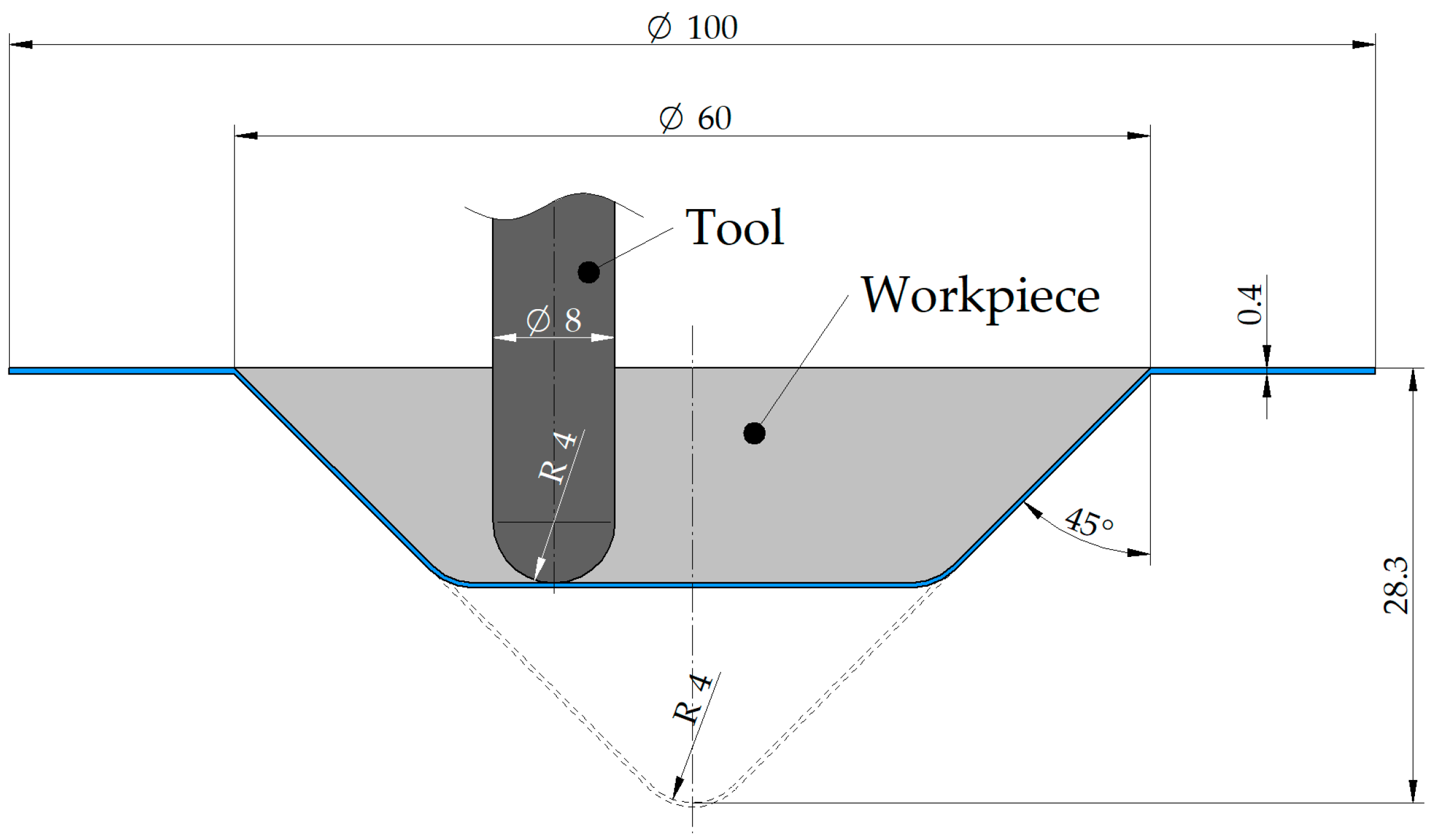
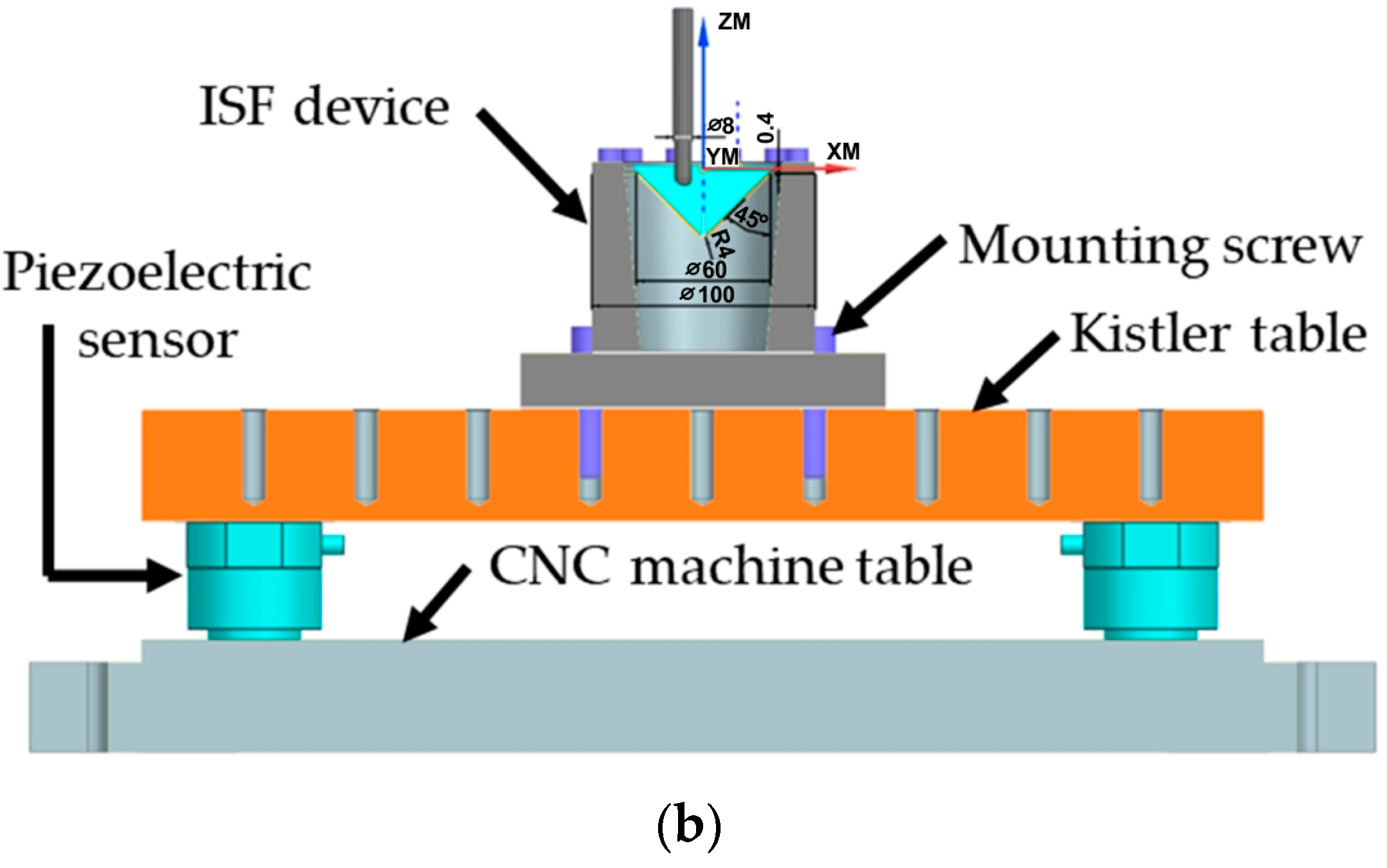
2.2. Experimental Setup
2.3. Optical Forming Analysis
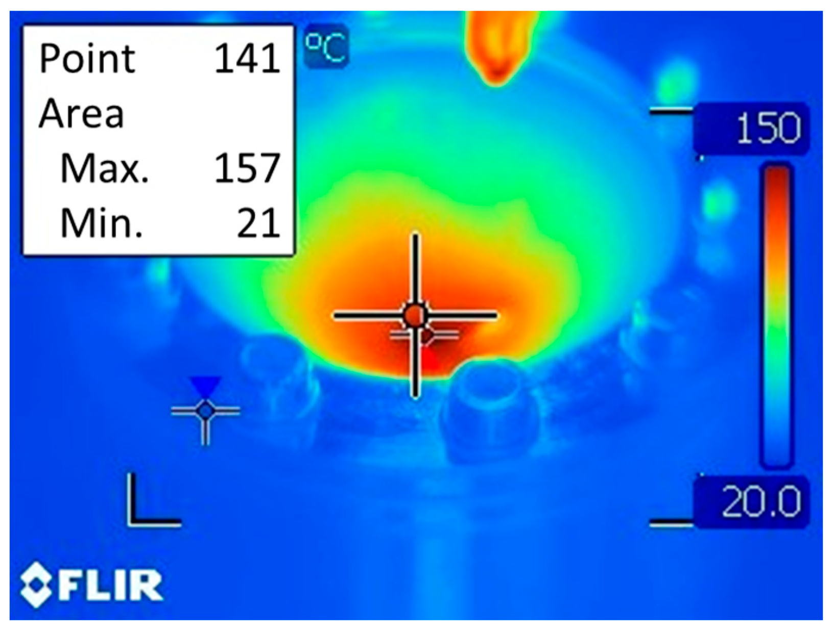
2.4. Temperature Measurement
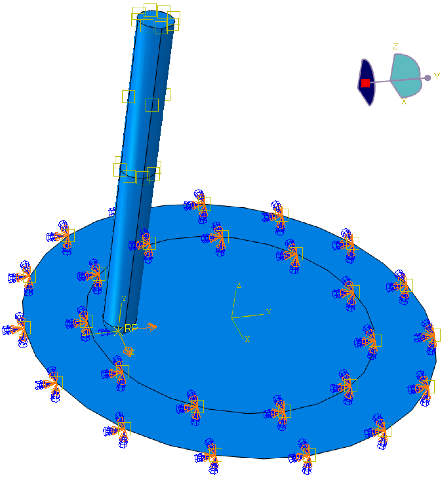
2.5. Numerical Modeling
3. Results and Discussion
4. Conclusions
- (a)
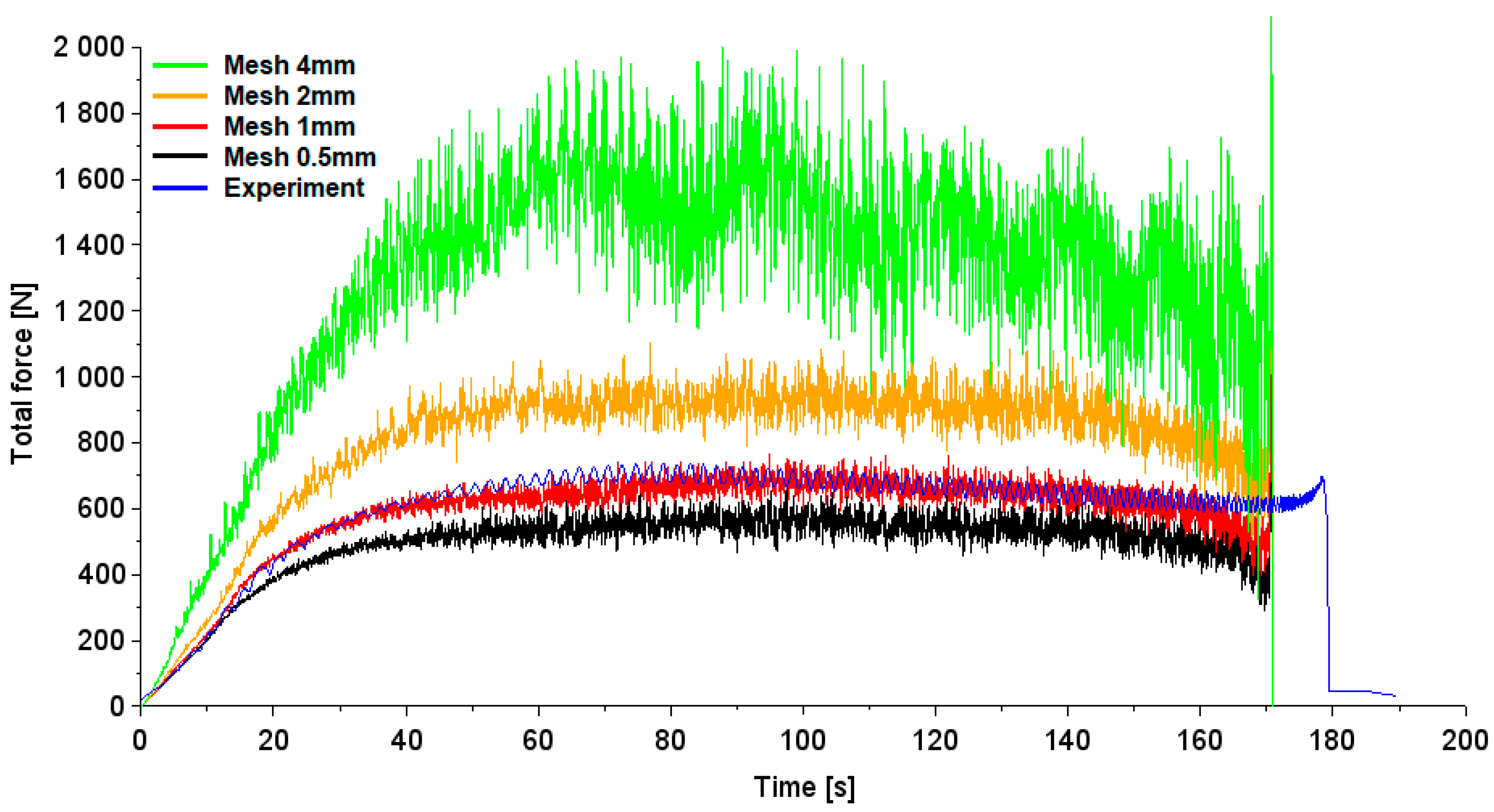
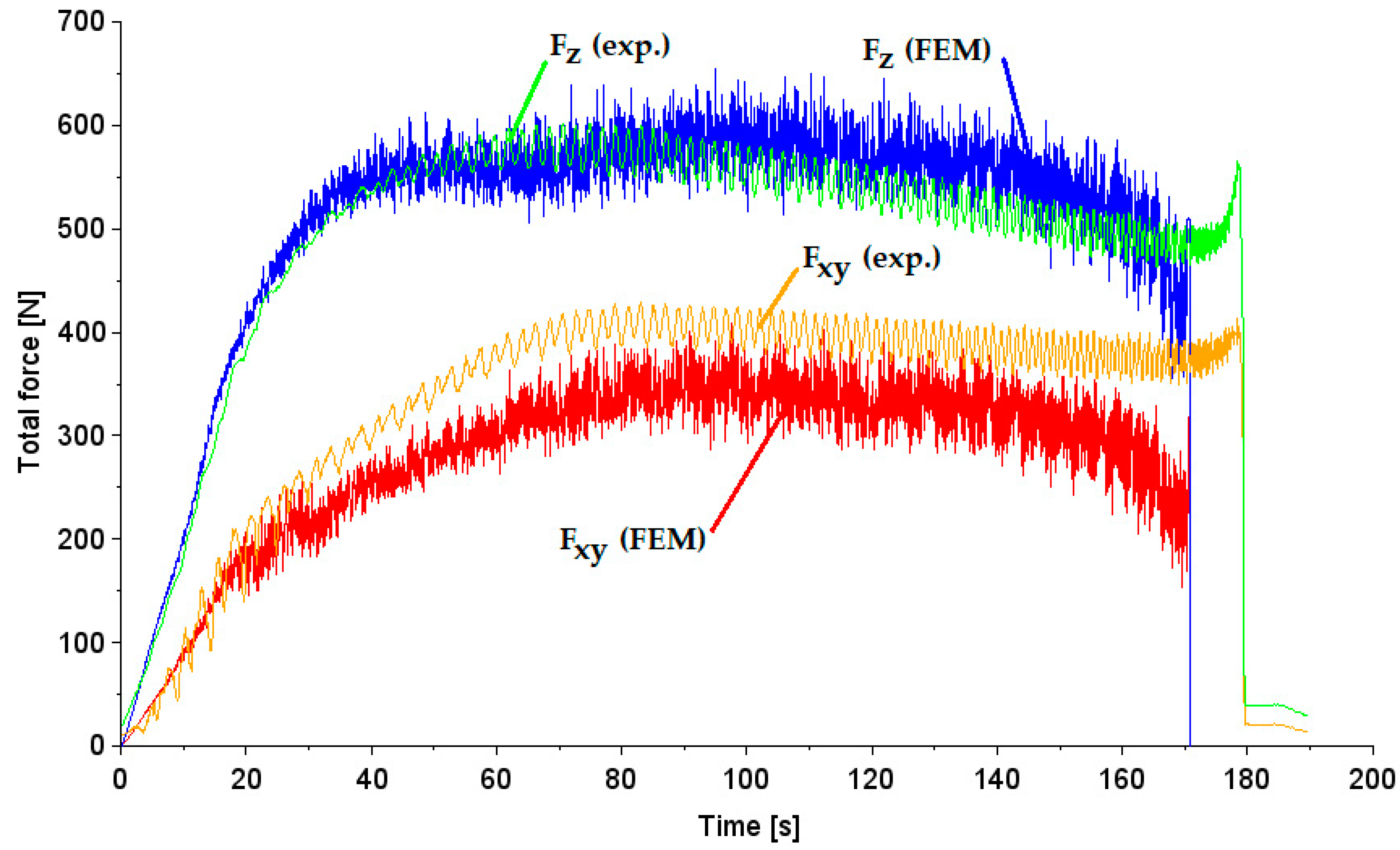
- The results of mesh sensitivity analysis showed that the predicted total forming force is most similar to the experiment for the numerical model containing a finite element mesh with a size of 1 mm. The average prediction error for the stabilized range of total forming force values was 2%.
- (b)
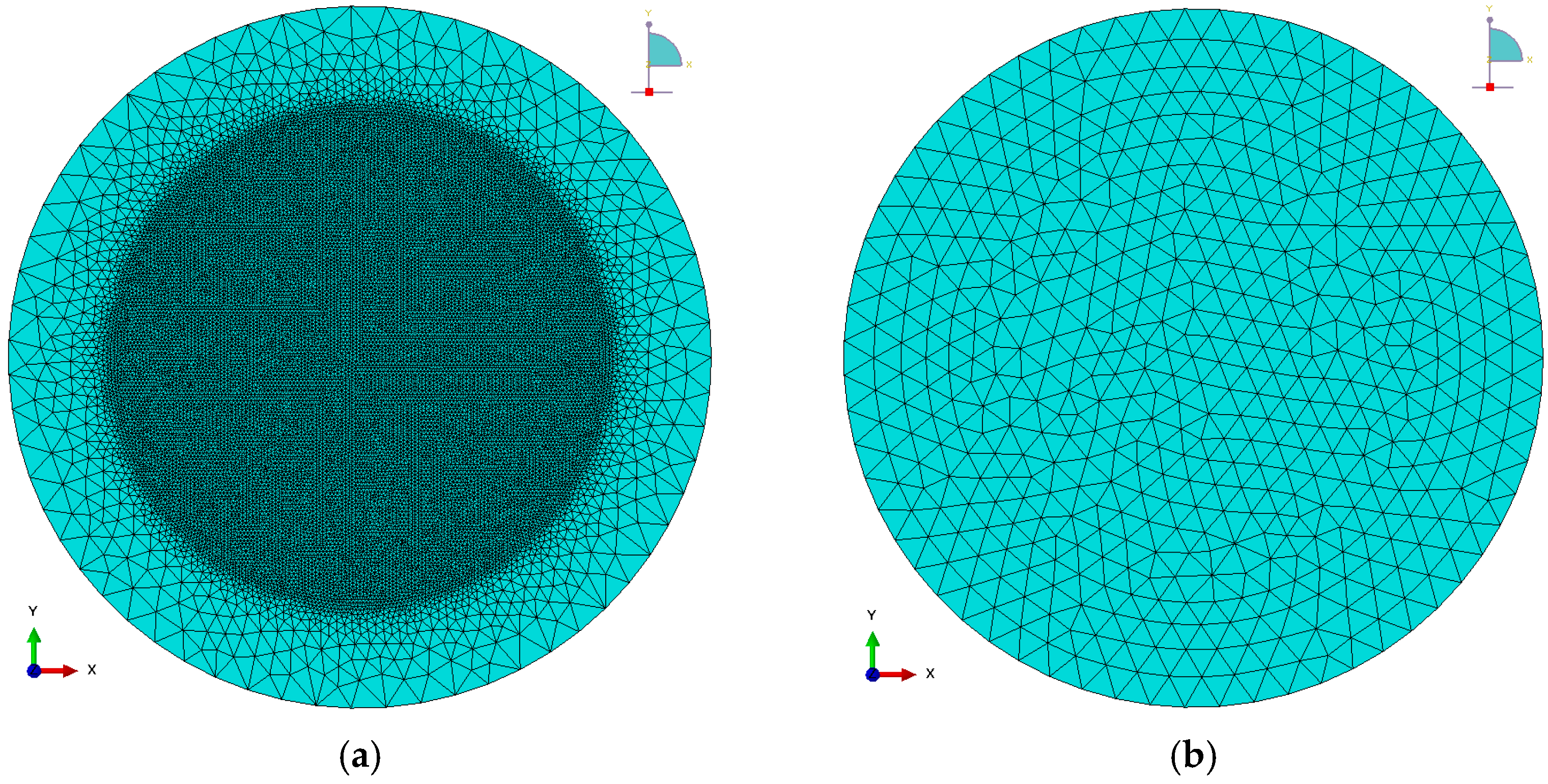
- It was observed that the higher the finite element size, the greater the fluctuations of the total forming force. This force is determined temporarily based on the contact surface area, i.e., the number of finite element nodes of the sheet metal in contact with the non-deformable tool. Thus, with large finite element sizes, there are large instabilities in the calculations of forming parameters.
- (c)
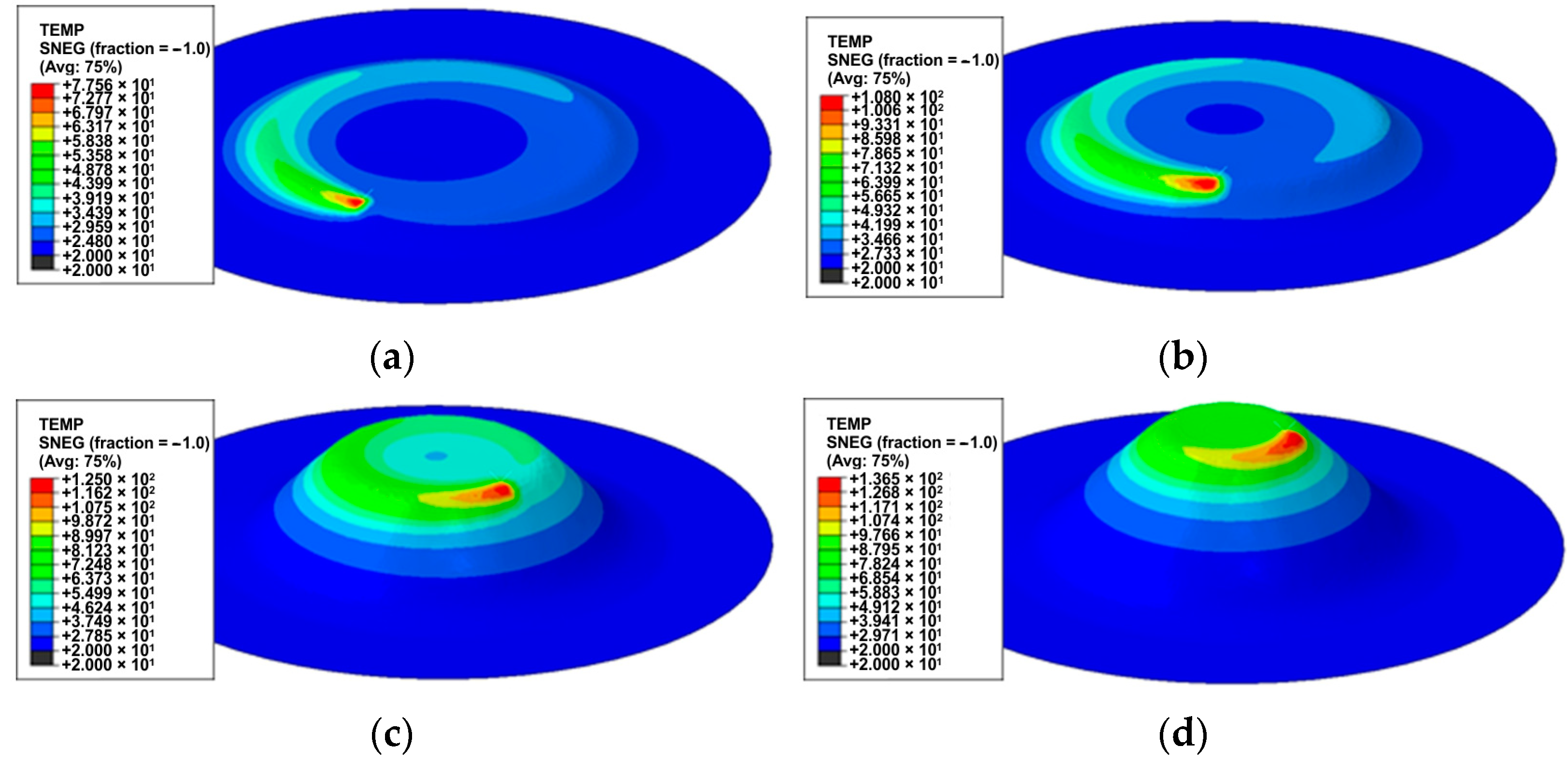
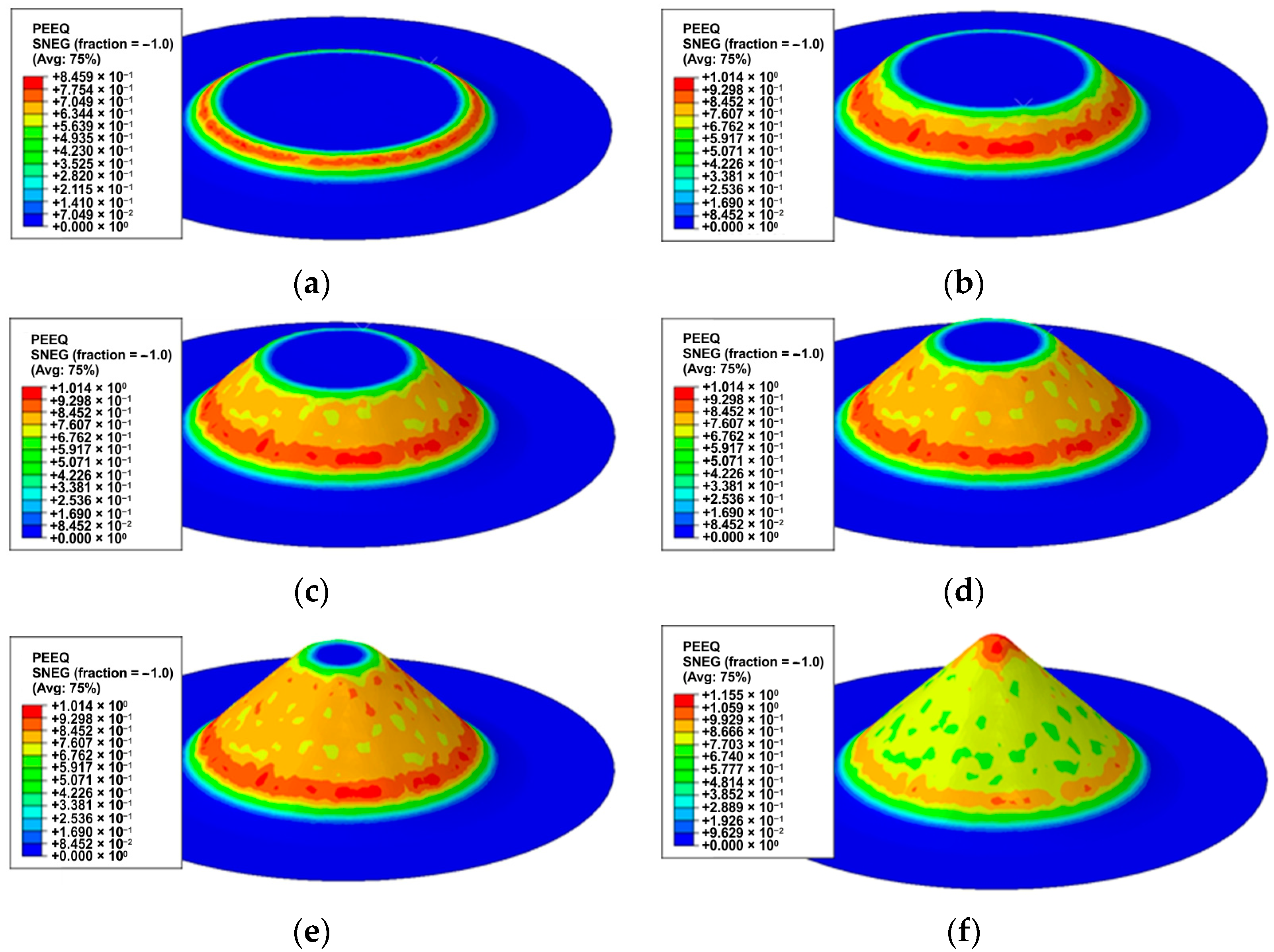
- As the height of conical drawpieces increases, their diameter in horizontal sections decreases, the material pushing effect decreases, and thus a trend of reducing in-plane and axial forces is observed. At the same time, during friction stir rotation-assisted SPIF, the temperature in the contact zone gradually increases, improving the sheet metal formability.
- (d)
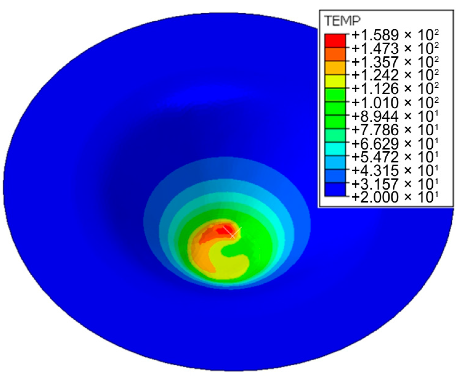
- The maximum temperature observed in the contact zone using the FLIR T400 infrared camera was 157 °C, while the FE-based model predicted this value with an error of 1.3%.
- (e)
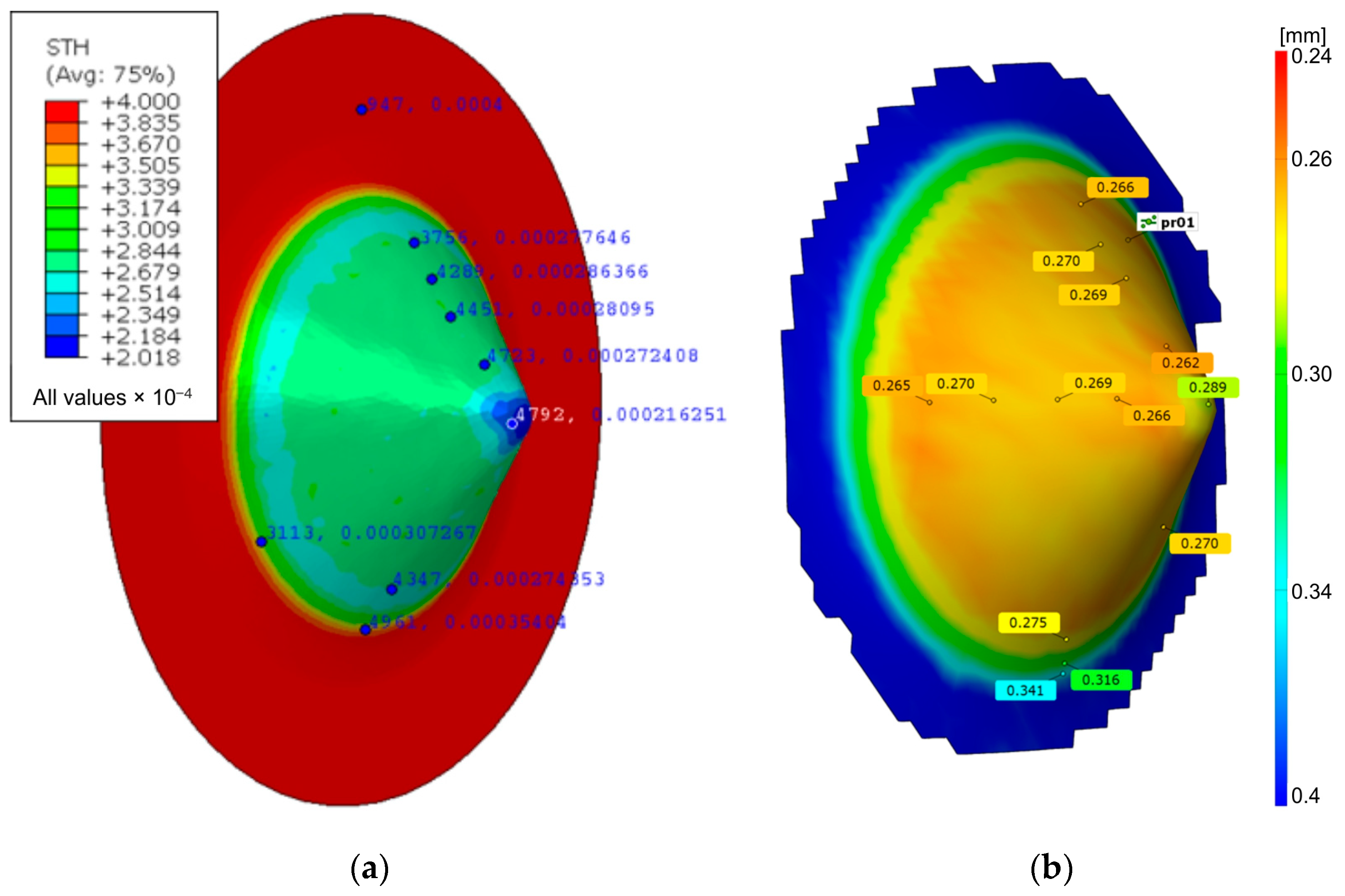
- The thinning detected by optical measurement of the drawpiece and predicted by the FEM model showed a uniform thickness in the drawpiece wall zone. The thickness of the side wall of the drawpiece, measured with an optical system with a strain measuring accuracy of 0.01%, varied between 0.262 and 0.27 mm. Meanwhile, the numerically calculated wall thickness was between 0.272 and 0.286 mm. So, the numerical model overestimated the minimum and maximum wall thickness by 3.7 and 5.9%, respectively.
- (f)
- The intensity of material heating in the initial stage of SPIF is limited due to the long path of the tool during one revolution along the helical path and the intense heat dissipation to the environment. As the height of the conical drawpiece increases, the material temperature in the immediate vicinity of the contact interface increases because the radius of the tool path decreases at a constant feed rate. Taking into account that the drawpiece is formed to some extent by the thinning of the previously formed side wall of the drawpiece, it would be beneficial to check how additional hot-air contactless heating or fluid-heating the workpiece will affect the formability of the material. This will be one of the topics of future research.
Author Contributions
Funding

Institutional Review Board Statement
Informed Consent Statement
Data Availability Statement
Conflicts of Interest
References
- Williams, J.C.; Boyer, R.R. Opportunities and issues in the application of titanium alloys for aerospace components. Metals 2020, 10, 705. [Google Scholar] [CrossRef]
- Kajal, G.; Tyagi, M.R.; Kumar, G. A review on the effect of residual stresses in incremental sheet metal forming used in automotive and medical sectors. Mater. Today Proc. 2023, 78, 524–534. [Google Scholar] [CrossRef]
- Gurrappa, I. Characterization of titanium alloy Ti-6Al-4V for chemical, marine and industrial applications. Mater. Charact. 2003, 51, 131–139. [Google Scholar] [CrossRef]
- Siengchin, S. A review on lightweight materials for defence applications: Present and future developments. Def. Technol. 2023, 24, 1–17. [Google Scholar] [CrossRef]
- Tubielewicz-Michalczuk, M. Application of titanium properties in civil engineering and architecture. Key Eng. Mater. 2016, 687, 220–227. [Google Scholar]
- Adamus, J. Wybrane problemy kształtowania blach tytanowych. Obróbka Plast. Met. 2008, 19, 29–36. [Google Scholar]
- Więckowski, W.; Motyka, M.; Adamus, J.; Lacki, P.; Dyner, M. Numerical and experimental analysis of titanium sheet forming for medical instrument parts. Materials 2022, 15, 1735. [Google Scholar] [CrossRef] [PubMed]
- Chen, F.K.; Chiu, K.H. Formability of pure titanium sheets. In Proceedings of the 11th International Conference Achievements in Mechanical & Materials Engineering, Gliwice-Zakopane, Poland, 15–18 December 2002; pp. 39–46. Available online: http://jamme.acmsse.h2.pl/papers_amme02/1111.pdf (accessed on 1 May 2023).
- Adamus, J.; Lacki, P.; Motyka, M. EBW titanium sheets as material for drawn parts. Arch. Civ. Mech. Eng. 2015, 15, 42–47. [Google Scholar] [CrossRef]
- Beal, J.D.; Boyer, R.; Sanders, D. Forming of titanium and titanium alloys. In ASM Handbook, Volume 14B: Metalworking: Sheet Forming; Semiatin, S.L., Ed.; ASM International: Detroit, MI, USA; pp. 656–669.
- Petek, A.; Gantar, G.; Pepelnjak, T.; Kuzman, K. Economical and ecological aspects of single point incremental forming versus deep drawing technology. Key Eng. Mater. 2007, 344, 931–938. [Google Scholar]
- Ohwue, T.; Shindo, T.; Hayashi, T. Square shell deep drawability of commercially pure titanium sheet. Nippon Steel Tech. Rep. 2002, 85, 125–128. [Google Scholar]
- Shipton, M.H.; Roberts, W.T. Hot deep drawing of titanium sheet. Mater. Sci. Technol. 1991, 7, 537–540. [Google Scholar] [CrossRef]
- Balyts’kyi, O.I.; Kolesnikov, V.O.; Eliasz, J. Study of the wear resistance of high-nitrogen steels under dry sliding friction. Mater. Sci. 2013, 48, 642–646. [Google Scholar] [CrossRef]
- Balyts’kyi, O.I.; Kolesnikov, V.O.; Kawiak, P. Triboengineering properties of austenitic manganese steels and cast irons under the conditions of sliding friction. Mater. Sci. 2005, 41, 624–630. [Google Scholar] [CrossRef]
- Akamatsu, T.; Ukita, S.; Miyasaka, K.; Shi, M. Deep drawing of commercially pure titanium sheets. ISIJ Int. 1995, 35, 56–62. [Google Scholar] [CrossRef]
- Harada, Y.; Ueyama, M. Formability of pure titanium sheet in square cup deep drawing. Procedia Eng. 2014, 81, 881–886. [Google Scholar] [CrossRef]
- Leszak, E. Apparatus and Process for Incremental Dieless Forming. U.S. Patent 3342051A1, 19 September 1967. [Google Scholar]
- Najm, S.M.; Paniti, I. Predict the effects of forming tool characteristics on surface roughness of aluminum foil components formed by SPIF using ANN and SVR. Int. J. Precis. Eng. Manuf. 2021, 22, 13–26. [Google Scholar] [CrossRef]
- Emments, W.C.; Sebastiani, G.; van den Boogaard, A.H. The technology of incremental sheet forming—A brief review of the history. J. Mater. Process. Technol. 2010, 210, 981–997. [Google Scholar] [CrossRef]
- Trzepiecinski, T.; Lemu, H.G. Recent developments and trends in the friction testing for conventional sheet metal forming and incremental sheet forming. Metals 2020, 10, 47. [Google Scholar] [CrossRef]
- Milutinović, M.; Lendjel, R.; Baloš, S.; Zlatanović, D.L.; Sevšek, L.; Pepelnjak, T. Characterisation of geometrical and physical properties of a stainless steel denture framework manufactured by single-point incremental forming. J. Mater. Res. Technol. 2021, 10, 605–623. [Google Scholar] [CrossRef]
- McAnulty, T.; Jeswiet, J.; Doolan, M. Formability in single point incremental forming: A comparative analysis of the state of the art. CIRP J. Manuf. Sci. Technol. 2017, 16, 43–54. [Google Scholar] [CrossRef]
- Oleksik, V.; Trzepieciński, T.; Szpunar, M.; Chodoła, Ł.; Ficek, D.; Szczęsny, I. Single-point incremental forming of titanium and titanium alloy sheets. Materials 2021, 14, 6372. [Google Scholar] [CrossRef] [PubMed]
- Rosca, N.; Oleksik, V.; Rosca, L.; Avrigean, E.; Trzepieciński, T.; Najm, S.M.; Oleksik, V. Minimizing the main strains and thickness reduction in the single point incremental forming process of polyamide and high-density polyethylene sheets. Materials 2023, 16, 1644. [Google Scholar] [CrossRef] [PubMed]
- Najm, S.M.; Paniti, I. Artificial neural network for modeling and investigating the effects of forming tool characteristics on the accuracy and formability of thin aluminum alloy blanks when using SPIF. Int. J. Adv. Manuf. Technol. 2021, 114, 2591–2615. [Google Scholar] [CrossRef]
- Rusu, G.P.; Oleksik, V.Ş.; Breaz, R.E.; Dobrotă, D.; Popp, I.O. Analysis of the metal sheets formability at single point incremental forming process. MATEC Web Conf. 2022, 368, 01006. [Google Scholar] [CrossRef]
- Şen, N.; Şirin, Ş.; Kıvak, T.; Civek, T.; Seçgin, Ö. A new lubrication approach in the SPIF process: Evaluation of the applicability and tribological performance of MQL. Tribol. Int. 2022, 171, 107546. [Google Scholar] [CrossRef]
- Behera, A.K.; de Sousa, R.A.; Ingarao, G.; Oleksik, V. Single point incremental forming: An assessment of the progress and technology trends from 2005 to 2015. J. Manuf. Process. 2017, 27, 37–62. [Google Scholar] [CrossRef]
- Trzepieciński, T.; Szpunar, M. Prediction of the coefficient of friction in the single point incremental forming of truncated cones from a Grade 2 titanium sheet. Tribol. Finn. J. Tribol. 2023, 40, 4–17. [Google Scholar]
- Shafeek, M.; Namboothiri, V.N.N.; Raju, C. Formability analysis on titanium Grade2 sheets in multi point incremental forming process. Mater. Today Proc. 2022, 65, 3814–3819. [Google Scholar] [CrossRef]
- Uheida, E.H.; Oosthuizen, G.A.; Dimitrov, D. Investigating the impact of tool velocity on the process conditions in incremental forming of titanium sheets. Procedia Manuf. 2017, 7, 345–350. [Google Scholar] [CrossRef]
- Hussain, G.; Gao, L.; Nayat, N.; Cui, Z.; Pang, Y.C.; Dar, N.U. Tool and lubrication for negative incremental forming of a commercially pure titanium sheet. J. Mater. Process. Technol. 2008, 203, 193–201. [Google Scholar] [CrossRef]
- Ambrogio, G.; Gagliardi, F.; Brushi, S.; Filice, L. On the high-speed single point incremental forming of titanium alloys. CIRP Ann. Manuf. Technol. 2013, 62, 243–246. [Google Scholar] [CrossRef]
- Nguyen, T.H.; Le, K.D.; Nguyen, N.P.; Nguyen, H.B.; Nguyen, T.N.; Vo, T. The effect of heating to the formability of titanium sheet by SPIF technology. Key Eng. Mater. 2017, 749, 171–177. [Google Scholar]
- Hussain, G.; Al-Ghamdi, K.A. PEO coating as lubrication means for SPIF of titanium sheet: Characteristics and performance. Mater. Res. Innov. 2014, 18, 727–733. [Google Scholar] [CrossRef]
- Behera, A.K.; Lu, B.; Ou, H. Characterization of shape and dimensional accuracy of incrementally formed titanium sheet parts. Matec Web Conf. 2015, 21, 04014. [Google Scholar] [CrossRef]
- Behera, A.K.; Lu, B.; Ou, H. Characterization of shape and dimensional accuracy of incrementally formed titanium sheet parts with intermediate curvatures between two feature types. Int. J. Adv. Manuf. Technol. 2016, 83, 1099–1111. [Google Scholar] [CrossRef]
- Sadiq, D.M.; Abed, I.J.; Gatea, S. Evaluation of effect of parameter on single point incremental forming of titanium. Kufa J. Eng. 2023, 14, 42–55. [Google Scholar] [CrossRef]
- Pande, A.; Barve, S. Implementation of Incremental Sheet Forming on Commercial Pure Titanium Sheet. Available online: https://www.indiaassignmenthelp.com/uploads/1682421900Implementation%20of%20Incremental%20Sheet%20Forming%20on%20Commercial%20Pure%20Titanium%20Sheet.docx (accessed on 1 May 2024).
- Adamus, J.; Winowiecka, J.; Dyner, M.; Lacki, P. Numerical simulation of forming titanium thin-wall panels with stiffeners. Adv. Sci. Technol. Res. J. 2018, 12, 54–62. [Google Scholar] [CrossRef]
- EN ISO 6892-1; Metallic Materials—Tensile Testing—Part 1: Method of Test at Room Temperature. International Organization for Standardization: Geneva, Switzerland, 2019.
- ASTM E21-20; Standard Test Methods for Elevated Temperature Tension Tests of Metallic Materials. ASTM International: West Conshohocken, PA, USA, 2020.
- Tayebi, P.; Fazli, A.; Asadi, P.; Soltanpour, M. Formability study and metallurgical properties analysis of FSWed AA 6061 blank by the SPIF process. SN Appl. Sci. 2021, 3, 367. [Google Scholar] [CrossRef]
- Szpunar, M.; Balcerzak, M.; Żaba, K. Shape Accuracy in single point incremental forming of conical frustums from titanium CP2 sheets. Sci. Lett. Rzesz. Univ. Technol. Mech. 2022, 39, 63–75. [Google Scholar] [CrossRef]
- ISO 513; Classification and Application of Hard Cutting Materials for Metal Removal with Defined Cutting Edges—Designation of the Main Groups and Groups of Application. International Organization for Standardization: Geneva, Switzerland, 2012.
- Jawale, K.; Duarte, J.F.; Reis, A.; Silva, M.B. Lubrication study for single point incremental forming of copper. J. Phys. Conf. Ser. 2016, 734, 032038. [Google Scholar] [CrossRef]
- Szpunar, M.; Trzepieciński, T.; Ostrowski, T.; Zwolak, M. Research on forming parameters optimization of incremental sheet forming process for commercially pure titanium grade 2 sheet. Arch. Metall. Mater. 2022, 67, 1411–1418. [Google Scholar] [CrossRef]
- Optical Strain Measuring System GOM ARGUS/ARAMIS. Available online: https://www.ibf.rwth-aachen.de/go/id/rkcr/lidx/1 (accessed on 16 May 2024).
- Naranjo, J.; Miguel, V.; Martinez, A.; Coello, J.; Manjabacas, M.C.; Valera, J. Influence of temperature on alloy Ti6Al4V formability during the warm SPIF process. Procedia Eng. 2017, 207, 866–871. [Google Scholar] [CrossRef]
- Ambrogio, G. Influence of some relevant process parameters on the dimensional accuracy in incremental forming: A numerical and experimental investigation. J. Mater. Process. Technol. 2004, 153–154, 501–507. [Google Scholar] [CrossRef]
- Saidi, B. Prédictions des Efforts de Formage Incrémental à un Point SPIF. Master’s Thesis, École Supérieure des Sciences et Technique de Tunis, Tunis, Tunisia, 2013. [Google Scholar]
- Filice, L.; Ambrogio, G.; Micari, F. On-line control of single point incremental forming operations through punch force monitoring. CIRP Ann. 2006, 55, 245–248. [Google Scholar] [CrossRef]
- Rosca, N.; Oleksik, M.; Rosca, L. Numerical-experimental study regarding the single point incremental forming process. MATEC Web Conf. 2021, 343, 03008. [Google Scholar] [CrossRef]
- Formisano, A.; Boccarusso, L.; Durante, M. Optimization of single-point incremental forming of polymer sheets through FEM. Materials 2023, 16, 451. [Google Scholar] [CrossRef]
- Ravichandran, S.; Duraiswamy, R.; Arockiasamy, F.S. Tool and formability multi-response optimization for ultimate strength and ductility of AA8011 during axial compression. Adv. Mech. Eng. 2022, 14, 1–12. [Google Scholar] [CrossRef]
- Liu, Z. Friction stir incremental forming of AA7075-O Sheets: Investigation on process feasibility. Procedia Eng. 2017, 207, 783–788. [Google Scholar] [CrossRef]
- Chen, C.; Han, D.; Song, Y.; Wang, M.; Li, Y.; Xu, S.; Yang, S.; Liu, J. Effect of grain size and temperature on deformation mechanism of commercially pure titanium. Trans. Nonferrous Met. Soc. China 2023, 33, 3332–3347. [Google Scholar] [CrossRef]
- Limpadapun, K.; Kesvarakul, R. An investigation of thickness distribution in Single-Point incremental forming with different forming parameter in hot-dipped zinc-coated cold-rolled steel. Mater. Today Proc. 2020, 33, 1988–1992. [Google Scholar] [CrossRef]
- Yang, M.; Yao, Z.; Li, Y.; Li, P.; Cui, F.; Bai, L. Study on Thickness Thinning Ratio of the Forming Parts in Single Point Incremental Forming Process. Adv. Mater. Sci. Eng. 2018, 2018, 2927189. [Google Scholar] [CrossRef]


| Test Temperature, °C | Yield Stress, MPa | Ultimate Tensile Stress, MPa | Elongation, % |
|---|---|---|---|
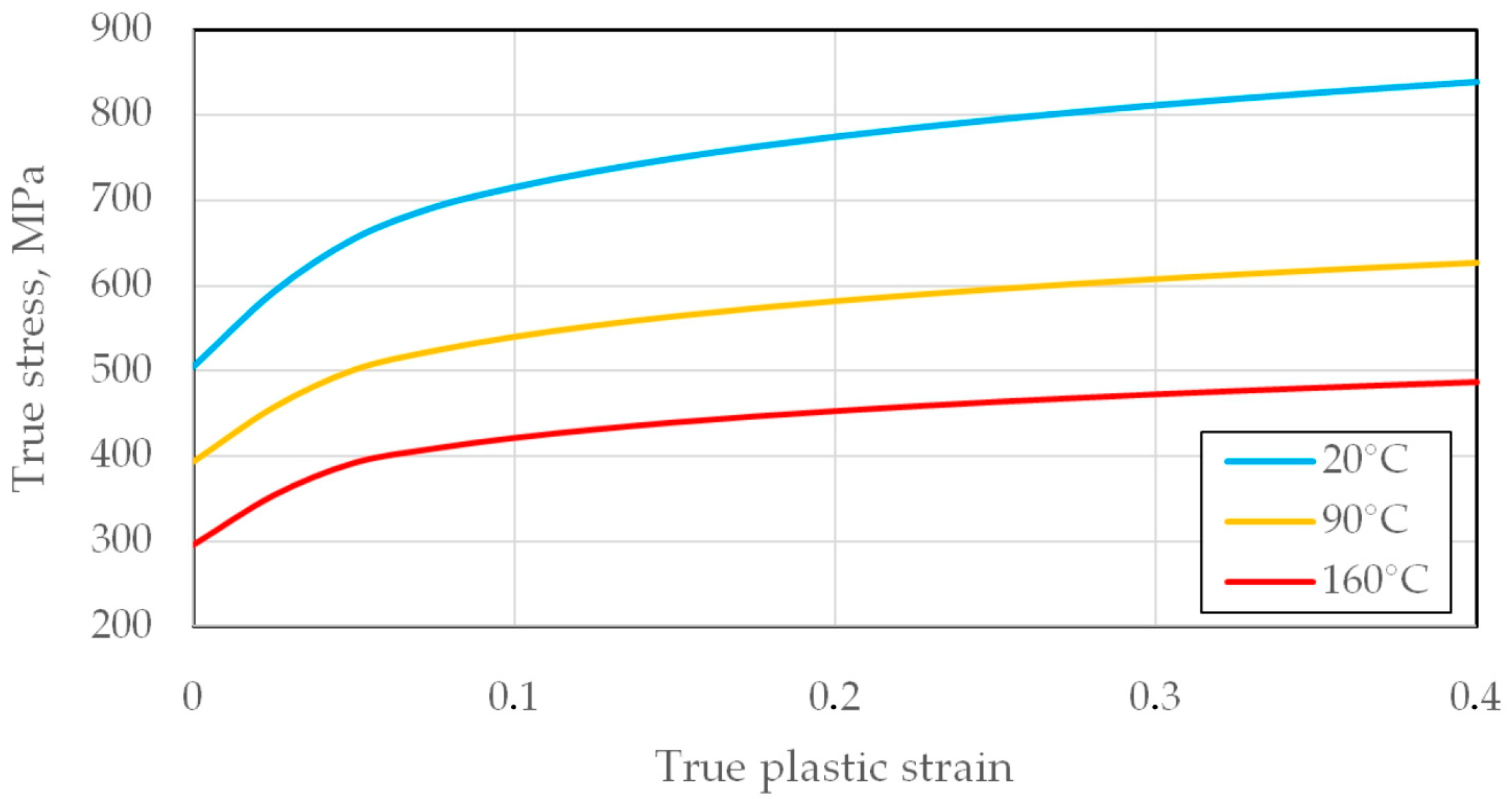
| 20 | 505 | 651 | 22.2 |
| 90 | 397 | 497 | 42.5 |
| 160 | 298 | 392 | 51.4 |
| Material | Young’s Modulus, GPa | Poisson’s Ratio | Density, kg·m−3 | Specific Heat, J·kg−1·°C−1 | Conductivity, W·m−1·°C−1 |
|---|---|---|---|---|---|
| Tool | 650 | 0.31 | 14,450 | 280 | 75 |
| Sheet metal | 105 | 0.37 | 4500 | 520 | 19.9 |
| Mesh Size, mm | Number of Elements | Number of Nodes | Computation Time |
|---|---|---|---|
| 0.5 | 36,659 | 18,362 | 3 h |
| 1 | 10,365 | 5215 | 1 h 5 min |
| 2 | 3271 | 1168 | 27 min |
| 4 | 1029 | 547 | 15 min |
Disclaimer/Publisher’s Note: The statements, opinions and data contained in all publications are solely those of the individual author(s) and contributor(s) and not of MDPI and/or the editor(s). MDPI and/or the editor(s) disclaim responsibility for any injury to people or property resulting from any ideas, methods, instructions or products referred to in the content. |
© 2024 by the authors. Licensee MDPI, Basel, Switzerland. This article is an open access article distributed under the terms and conditions of the Creative Commons Attribution (CC BY) license (https://creativecommons.org/licenses/by/4.0/).
Share and Cite
Szpunar, M.; Trzepieciński, T.; Ostrowski, R.; Żaba, K.; Ziaja, W.; Motyka, M. Thermo-Mechanical Numerical Simulation of Friction Stir Rotation-Assisted Single Point Incremental Forming of Commercially Pure Titanium Sheets. Materials 2024, 17, 3095. https://doi.org/10.3390/ma17133095
Szpunar M, Trzepieciński T, Ostrowski R, Żaba K, Ziaja W, Motyka M. Thermo-Mechanical Numerical Simulation of Friction Stir Rotation-Assisted Single Point Incremental Forming of Commercially Pure Titanium Sheets. Materials. 2024; 17(13):3095. https://doi.org/10.3390/ma17133095
Chicago/Turabian StyleSzpunar, Marcin, Tomasz Trzepieciński, Robert Ostrowski, Krzysztof Żaba, Waldemar Ziaja, and Maciej Motyka. 2024. "Thermo-Mechanical Numerical Simulation of Friction Stir Rotation-Assisted Single Point Incremental Forming of Commercially Pure Titanium Sheets" Materials 17, no. 13: 3095. https://doi.org/10.3390/ma17133095