Article

WO3/BiOBr S-Scheme Heterojunction Photocatalyst for Enhanced Photocatalytic CO2 Reduction

1
Guangxi Key Laboratory of Petrochemical Resource Processing and Process Intensification Technology, School of Chemistry and Chemical Engineering, Guangxi University, Nanning 530004, China
2
State Key Laboratory Breeding Base of Green-Chemical Synthesis Technology, Institute of Green Petroleum Processing and Light Hydrocarbon Conversion, College of Chemical Engineering, Zhejiang University of Technology, Hangzhou 310014, China
*
Author to whom correspondence should be addressed.
Materials 2024, 17(13), 3199; https://doi.org/10.3390/ma17133199
Submission received: 24 May 2024 / Revised: 15 June 2024 / Accepted: 25 June 2024 / Published: 30 June 2024
(This article belongs to the Special Issue Advanced Materials for Solar Energy Utilization)

Abstract

:
The photocatalytic CO2 reduction strategy driven by visible light is a practical way to solve the energy crisis. However, limited by the fast recombination of photogenerated electrons and holes in photocatalysts, photocatalytic efficiency is still low. Herein, a WO3/BiOBr S-scheme heterojunction was formed by combining WO3 with BiOBr, which facilitated the transfer and separation of photoinduced electrons and holes and enhanced the photocatalytic CO2 reaction. The optimized WO3/BiOBr heterostructures exhibited best activity for photocatalytic CO2 reduction without any sacrificial reagents, and the CO yield reached 17.14 μmol g−1 after reaction for 4 h, which was 1.56 times greater than that of BiOBr. The photocatalytic stability of WO3/BiOBr was also improved.

1. Introduction

The massive use of fossil fuel energy increases the amount of greenhouse gases, such as CO2, in the air, causing greenhouse effects, melting glaciers, and energy shortages [1,2,3]. Converting CO2 into chemical raw materials is a practical way to solve the environmental and energy crisis [4]. Among many technologies, photocatalytic reduction of CO2 to a chemical feedstock is a feasible way to achieve a green sustainable carbon cycle [5]. However, the low visible light absorption efficiency and recombination of the photoinduced electron-hole pairs in photocatalysts severely limit the efficiency of photocatalytic CO2 conversion [6,7]. Therefore, it is very significant to improve the photogenerated charge carriers separation in photocatalysts.
The construction of heterojunctions is considered to be beneficial for improving photocatalytic efficiency. Among various heterojunctions, S-scheme heterojunctions are widely studied due to their stronger redox ability [8]. In general, the S-scheme heterojunction includes an oxidation catalyst (OP) and a reduction catalyst (RP). When the RP is combined with the OP, the electrons will flow from the RP to the OP due to the higher Fermi level of the RP, resulting in the formation of an internal electric field at the interface. Under light irradiation, the electrons in the conduction band (CB) of OP combine with the holes in the valence band (VB) of RP due to the presence of an internal electric field, and the holes and electrons in the OP and RP can be used for oxidation or reduction reactions, respectively, thus promoting the separation of photogenerated electron-holes [9,10,11]. Therefore, the design of S-scheme heterojunctions with high charge carriers separation efficiency and strong redox capacity is a promising approach for improving photocatalytic efficiency.
Among many photocatalysts, bismuth-based photocatalysts have good photoelectric properties and are widely used in the fields of organic matter photodegradation and CO2 photoreduction [12,13]. Layered bismuth halides (BiOX, X = Cl, Br, and I) have been extensively studied due to their high photocatalytic performance [14]. BiOX consists of a bismuth–oxygen layer (Bi2O2)2+ and two alternatingly arranged Br layers. Such a layered structure can form an internal electric field to shorten the transmission distance of the photogenerated electrons, which is very favorable for photocatalytic reactions [15,16,17]. Notably, BiOBr has aroused wide concern due to its narrow band gap and suitable band structure. However, the rapid recombination of photoinduced charge carriers in BiOBr limits its application in photocatalytic CO2 reduction [18]. To improve the photocatalytic efficiency of BiOBr, numerous ways have been proposed, such as regulating oxygen vacancies [19], metal doping [20], and hybridization with various semiconductors [21,22,23]. The formation of an S-scheme heterojunction can be a feasible way to improve the photocatalytic efficiency of BiOBr [24,25,26]. The use of a suitable oxidized semiconductor combined with BiOBr to construct an S-scheme heterojunction can shorten the transfer distance of charge carriers, prolong the carrier lifetime, and enhance the redox ability. For instance, WO3 is widely used as the oxidizing photocatalyst due to its advantages of low cost, excellent photoelectric performance, and strong oxidation ability [27,28]. Moreover, WO3 has a suitable band structure and can form S-scheme heterojunctions with BiOBr, which is expected to enhance the performance of photocatalytic CO2 reduction.
In this work, WO3/BiOBr heterojunctions were prepared and used for photocatalytic CO2 reduction. Under visible light (λ ≥ 400 nm), the optimized WO3/BiOBr exhibited the best CO yield of 17.14 μmol g−1 irradiation for 4 h without the addition of sacrificial agents, which was 1.56 times higher than that of BiOBr. Combining the activity data and characterization results, the S-scheme charge transfer mechanism was demonstrated for WO3/BiOBr, which enhances the rapid transfer and separation of photoinduced charge carriers.

2. Experimental

2.1. Synthesis of the Photocatalyst

2.1.1. Materials

Bi(NO3)3·5H2O was obtained from Guangdong Guanghua Technology Co., Ltd. (Shantou, China). Polyvinylpyrrolidone (PVP, K-30) was purchased from Shanghai McLean Biochemical Technology Co., Ltd. (Shanghai, China). KBr was purchased from Tianjin Guangfu Technology Development Co., Ltd. (Tianjin, China). WO3 was purchased from Tianjin Bodi Chemical Co., Ltd. (Tianjin, China). All the chemical agents involved in this work were analytically pure and were used without further purification.

2.1.2. Preparation of BiOBr

First, 5 mmol of Bi(NO3)3·5H2O and 0.2 g of PVP were mixed in 40 mL deionized (DI) water and stirred for 60 min. At the same time, 5 mmol of KBr was dissolved in 40 mL of DI water and stirred for 60 min. After that, the above solution was mixed and stirred together, and the pH was adjusted to 6. The mixture was then stirred for 1 h and heated at 160 °C for 12 h. After cooling down, the mixture was washed with DI water several times and dried at 60 °C for 12 h in a vacuum drying oven.

2.1.3. Preparation of WO3/BiOBr

First, 0.2 g of BiOBr was dispersed in 40 mL DI water for 30 min by ultrasonication, and then a certain amount of WO3 (3, 5, 10 wt%) was added to the above suspension and stirred at 60 °C for 10 h by water bath. The sample was then washed with DI water and dried by vacuum drying at 60 °C for 12 h. The samples with different mass ratios were named 3WO3/BiOBr, 5WO3/BiOBr, and 10WO3/BiOBr.

2.2. Photocatalytic CO2 Reduction

First, 30 mg photocatalyst was dispersed evenly in 1.5 mL DI water by ultrasonication, and then the photocatalyst was evenly spread on a quartz sheet and dried at 60 °C in a vacuum drying oven. For the photocatalytic CO2 reduction, the quartz sheet with the photocatalyst was placed at the bottom of the reactor. After that, the wet CO2 was injected into the reactor for 30 min, with a flow quantity of 40 mL min−1 to ensure that the air was completely removed. A 300 W xenon lamp (CEL-HXF300, Beijing China Education Au-light Co., Ltd., Beijing, China) was applied as the light source for the reaction and a 400 nm cutoff filter was used to filter out light below 400 nm. The light intensity of the light source was determined to be 178 mW cm−2 by using an optical power meter (CENP2000, Beijing China Education Au-light Co., Ltd., Beijing, China). The reaction temperature was maintained at 25 °C by using circulating cooling water. Every hour, 0.5 mL of gas product was detected on a GC-2030 gas chromatograph (Shimadzu, Kyoto, Japan).

2.3. Characterization

The XRD patterns were obtained on a Bruker D8 X-ray diffractometer (BRUKER AXS GMBH, Karlsruhe, Germany). Fourier transform infrared spectra and in situ infrared spectra were recorded on a Bruker Tensor II infrared spectrometer (Bruker, Karlsruhe, Germany). SEM images were obtained on a ZEISS GeminiSEM 300 instrument (ZEISS, Oberkochen, Germany). TEM images and elemental mapping images were recorded on a JEOL JEM-F200 transmission electron microscope (JEOL, Tokyo, Japan). XPS spectra were performed on a Thermo Scientific K-Alpha instrument (Thermo Fisher Scientific, Waltham, MA, USA). Ultraviolet-visible diffuse reflectance spectra were analyzed by a TU-19 spectrophotometer (PERSEE ANALYTICS, Beijing, China). N2 adsorption and desorption curves were obtained on a Tristar II physical adsorption instrument (Micromeritics, Norcross, GA, USA). Time-resolved fluorescence spectra (TRPL) were analyzed on an Edinburgh FLS 1000 spectrometer (Edinburgh Instruments, Livingston, UK).

2.4. Photoelectrochemical Measurements

A CHI 760E electrochemical workstation was used for the photoelectrochemical measurements (Shanghai Chenhua Instrument Co., Ltd., Shanghai, China). The test was carried out in a three-electrode system, with an Ag/AgCl electrode, a Pt electrode, and a photocatalyst electrode used as the reference electrode, the counter electrode, and the working electrode, respectively. In addition, 0.5 M Na2SO4 was used as the electrolyte. To prepare the working electrode, 20 mg of photocatalyst was added to 400 μL absolute ethanol and 20 μL of Nafion® solution (Shanghai McLean Biochemical Technology Co., Ltd, Shanghai, China), and the mixture was ultrasonicated at 25 °C for 2 h. Then, 20 μL of the mixed solution was uniformly dropped on FTO conductive glass with a central area of 1 cm2 (2 cm × 2 cm) and the working electrode was dried naturally. The electrochemical impedance spectrum (EIS) was tested at an alternating amplitude of 5 mV and with a frequency from 0.01 to 1,000,000 Hz. The transient photocurrent response was tested with a 300 W xenon lamp (equipped with a 400 nm cutoff filter) as the light source. Mott–Schottky curves were obtained at frequencies of 1000, 1500, and 2000 Hz.

3. Results and Discussion

3.1. Structure and Morphology

The crystalline phase and composition of BiOBr, WO3, and xWO3/BiOBr were measured by XRD. From Figure 1a, the peaks of WO3 are consistent with the triclinic phase WO3 (PDF#20−1323) [29]. In the XRD patterns of BiOBr, the diffraction peaks at 10.9°, 25.1°, 31.7°, 32.2°, 46.2°, and 57.1° are ascribed to the (001), (101), (102), (110), (200), and (212) planes of the tetragonal phase BiOBr, respectively (PDF#09−0393) [30]. Notably, from Figure 1a and Figure S1, enlarged regions from 20° to 30° in XRD patterns of xWO3/BiOBr are shown in Figure S1, with the peaks at 23.1°, 23.6°, 24.4°, and 26.8° ascribed to the (002), (020), (200), and (120) planes of WO3 (PDF#20−1323), and the peak at 25.1° is attributed to the (101) plane of BiOBr (PDF#09−0393). Both the peaks of WO3 and BiOBr can be found in the XRD patterns of xWO3/BiOBr, indicating that the xWO3/BiOBr composites were successfully prepared.
FT–IR spectra were used to further study the structure of the obtained samples. Figure 1b shows that the peaks at 526 cm−1 are assigned to the tensile vibration of the Bi–O bond [31,32], and the peaks located in the range of 1000~1500 cm−1 region are ascribed to the asymmetric and symmetric vibrations of the Bi–Br bond [33,34]. The peaks of WO3 at 826 cm−1 are attributed to the W–O bond [35]. In addition, the peaks at 1654 cm−1 are attributed to the bending vibrations of the adsorbed H2O on the surface of BiOBr, and the peaks at 3436 cm−1 correspond to the stretching vibrations of the adsorbed OH groups [36]. However, due to the low content of WO3, the peaks of WO3 cannot be seen from the FT–IR spectra of xWO3/BiOBr.
The specific surface area and average pore diameter of the samples were studied by N2 adsorption and desorption. Figure 1c shows that all the samples have the type IV isotherms and type H3 hysteresis loops, indicating that the samples are mesoporous material [37]. The specific surface areas of BiOBr, WO3, 3WO3/BiOBr, 5WO3/BiOBr, and 10WO3/BiOBr are 19.64, 3.54, 14.81, 17.96, and 17.15 m2 g−1 (Table S1), respectively, indicating that the specific surface area of xWO3/BiOBr composites is slightly lower than that of BiOBr but much higher than that of WO3. Among the xWO3/BiOBr composites, 5WO3/BiOBr exhibits the largest specific surface area and can provide more reaction sites for photocatalytic reactions [38].
Scanning electron microscopy (SEM) and transmission electron microscopy (TEM) were used to investigate the morphology and microstructure of the catalyst (Figure 2). BiOBr shows the nanoflower structure assembled from many nanosheets, while WO3 has a polyhedral structure. From the SEM images of 5WO3/BiOBr, we can see that the BiOBr nanoflower was dispersed and covered on the surface of WO3, which is beneficial for increasing the contact interface between WO3 and BiOBr. In addition, the SEM images of 3WO3/BiOBr and 10WO3/BiOBr are also shown in Figure S2. The microstructure of 5WO3/BiOBr was further investigated by HRTEM. Figure 2e and Figure 2f are the enlarged regions of the white boxes in Figure 2d and Figure 2e, respectively. As shown in Figure 2f, the lattice fringe spacing of 0.33 and 0.28 nm is attributed to the (120) planes of WO3 [39] and (102) planes of BiOBr [40], respectively. Notably, a tight contact interface between WO3 and BiOBr is clearly observed, indicating the formation of the WO3/BiOBr heterojunction. Moreover, the lattice fringe of WO3 can also be observed close to the lattice fringe of BiOBr, indicating the successful construction of the heterointerface between WO3 and BiOBr. In addition, according to the EDS elemental mapping of 5WO3/BiOBr (Figure 2g–k), the Bi, O, Br, and W elements are evenly distributed in the 5WO3/BiOBr composite. According to the EDX spectrum (Figure S3), the Bi, Br, O, and W elements exist in 5WO3/BiOBr and the mass fraction and atomic fraction of W are 2.23% and 1.31%. These results indicate the successful synthesis of 5WO3/BiOBr composites.

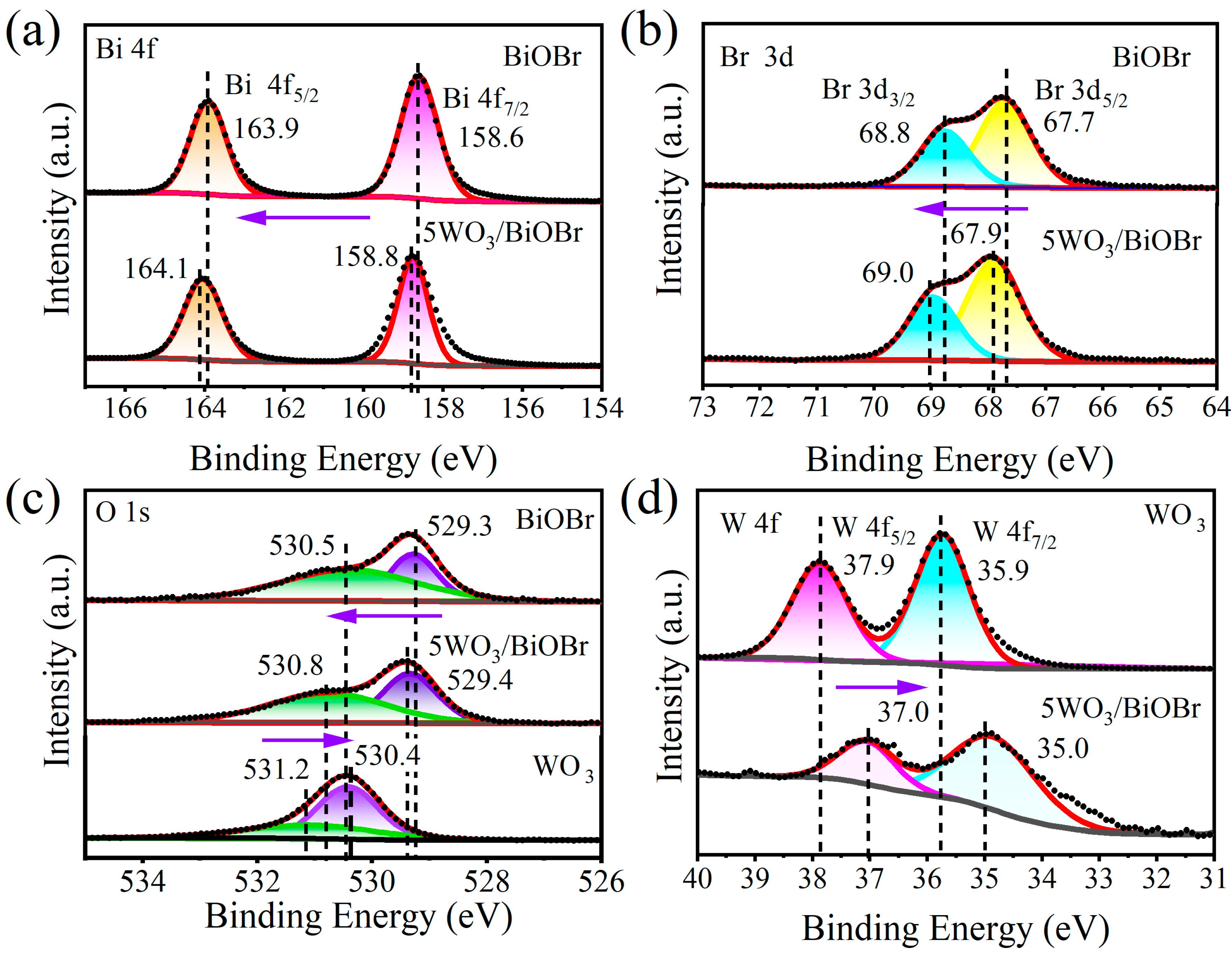
3.2. Surface Chemical State

The surface chemical state of the photocatalysts was investigated by XPS spectra. The XPS survey spectra of BiOBr, WO3, and 5WO3/BiOBr display that Bi, O, Br, and W elements are present in 5WO3/BiOBr, which demonstrates the successful synthesis of 5WO3/BiOBr (Figure S4). The enlarged spectral regions from 0 eV to 100 eV in the XPS survey spectra of BiOBr, WO3, and 5WO3/BiOBr are shown in Figure S4b. The peaks of Bi 5d, O 2s, W 4f7/2, and W 4f5/2 are found at 25.9, 25.9, 35.9, and 37.9 eV, respectively. Overtly, no WO3 signal was found in enlarged spectral regions from 0 eV to 100 eV of BiOBr.
Figure 3 shows the XPS spectra of Bi 4f, Br 3d, O 1s, and W 4f. As can be seen from the XPS spectra of BiOBr (Figure 3a), the two peaks at 158.6 and 163.9 eV are ascribed to Bi 4f7/2 and Bi 4f5/2 for Bi3+, respectively. Compared to BiOBr, the binding energies of Bi 4f7/2 and Bi 4f5/2 in 5WO3/BiOBr shifted to 158.8 and 164.1 eV, respectively [41,42]. From the Br 3d spectra of BiOBr and 5WO3/BiOBr (Figure 3b), two peaks at 68.8 and 67.7 eV are attributed to Br 3d3/2 and Br 3d5/2, respectively, indicating the presence of Br [43], while the binding energies of Br 3d3/2 and Br 3d5/2 in 5WO3/BiOBr shift to 69.0 and 67.9 eV, respectively. The shift of the Bi 4f5/2, Bi 4f7/2, Br 3d3/2, and Br 3d5/2 in 5WO3/BiOBr indicates that the electrons were migrated from BiOBr to WO3 after BiOBr was contacted with WO3.
As shown in the O 1s spectra of BiOBr, WO3, and 5WO3/BiOBr (Figure 3c), the binding energy of W–O is located at 530.4 and 531.2 eV for WO3 [44], the binding energy of Bi–O is located at 529.3 and 530.5 eV for BiOBr [45], and the peaks shift to 529.4 and 530.8 eV, respectively, in the O 1s XPS spectrum of 5WO3/BiOBr, indicating that the chemical environment was changed after the formation of the WO3/BiOBr heterojunction. In addition, two peaks located at 37.9 and 35.9 eV were found in the W 4f XPS spectrum of WO3, which correspond to W 4f5/2 and W 4f7/2 for W6+ [46], respectively (Figure 3d). In the XPS spectra of 5WO3/BiOBr, W 4f5/2 and W 4f7/2 shifted to 37.0 and 35.0 eV, respectively, indicating that the electron cloud density of the W in WO3 was increased. The above result indicates that the electrons in BiOBr can migrate to WO3 through the interface after WO3 was coupled with BiOBr, and a built-in electric field was constructed at the WO3/BiOBr interface [47,48].

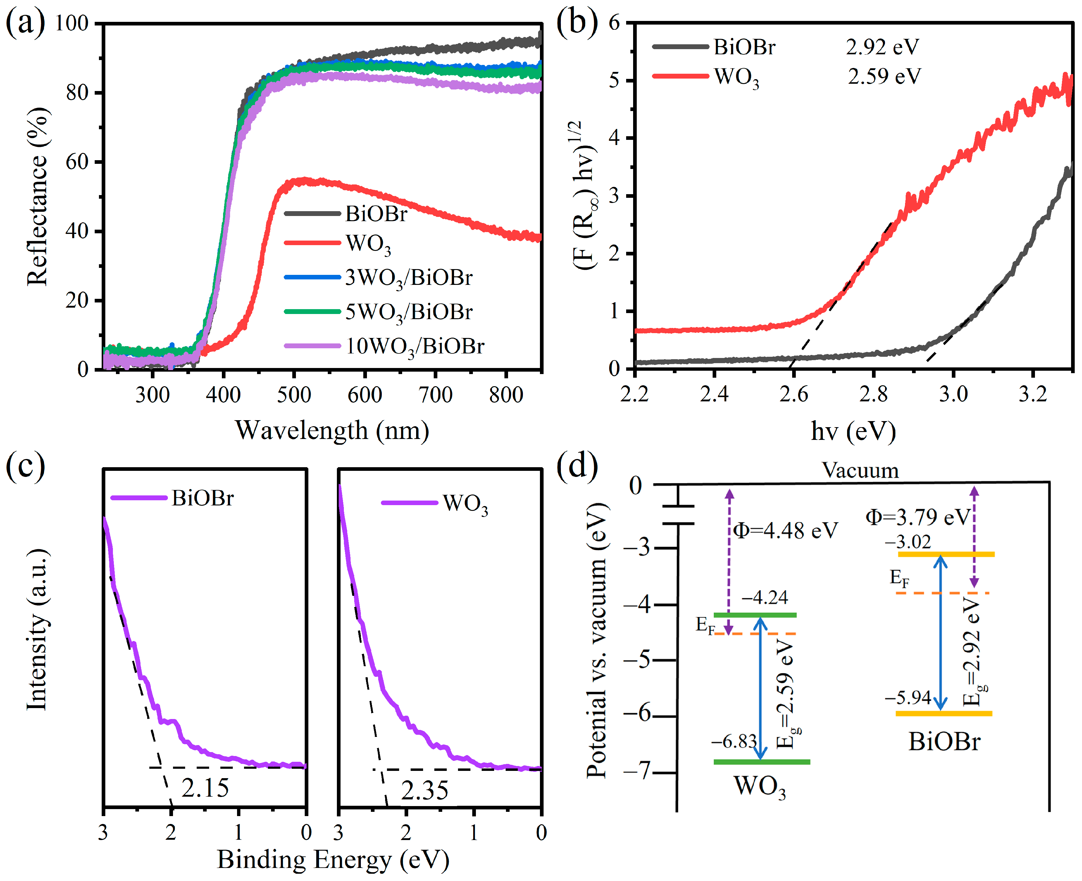
3.3. Light Absorption Capacity and Band Structure

The light absorption capacity and band structures of WO3, BiOBr, and 5WO3/BiOBr were analyzed by UV–Vis DRS and UPS spectroscopy (Figure 4). As shown in Figure 4a, WO3 shows obvious visible light absorption. However, no significant changes were observed for the light absorption capacity of BiOBr after the introduction of WO3. The band gaps of BiOBr and WO3 were determined to be 2.92 and 2.59 eV by the Kubelka-Munk method, respectively (Figure 4b), which is in accordance with the results in the literature [49,50].
UPS spectra were carried out to analyze the work function (Φ) and valence band (VB) of the catalyst (Figure 4c and Figure S5). As shown in the UPS spectra of BiOBr and WO3 (Figure S5), the secondary electron cutoff edges (Ecutoff) of BiOBr and WO3 are 17.43 and 16.74 eV, respectively. As a result, the work functions of BiOBr and WO3 were calculated to be 3.79 and 4.48 eV, respectively, according to Equation S1 [51]. In addition, the value of the work function is equal to the difference value between the vacuum level (Ev) and the Fermi level (Ef). Herein, the value of the vacuum level is identified as 0 eV [52], and the Fermi levels of BiOBr and WO3 were calculated to be −3.79 and −4.48 eV relative to the vacuum level. In addition, as shown in Figure 4c, the valence band (VB) values of BiOBr and WO3 are 2.15 and 2.35 eV relative to the Fermi level, respectively. Therefore, the VB values of BiOBr and WO3 were calculated to be −5.94 and −6.83 eV (vs. vacuum), respectively [53]. Therefore, the conduction band (CB) values of BiOBr and WO3 were determined to be −3.02 and −4.24 eV (vs. vacuum), respectively [54]. As shown in the band structures of BiOBr and WO3 (Figure 4d), the electrons in BiOBr will transfer to WO3 due to the higher work function of WO3, and a built-in electric field can be formed at the WO3/BiOBr interface, which is in favor of enhancing the separation of photoinduced electron-hole pairs.
In addition, Mott–Schottky plots were obtained to analyze the flat-band potentials (Efb) of the samples. From Figure S6, the positive slopes of the Mott–Schottky plots indicate that both BiOBr and WO3 are n-type semiconductors [55]. The Efb values of BiOBr and WO3 were determined to be −0.45 and −0.26 V (vs. Ag/AgCl, pH = 7), respectively. According to Equation (S2) [56], the Efb values of BiOBr and WO3 were calculated to be 0.16 and 0.35 V (vs. NHE, pH = 0), respectively. In general, for n-type semiconduction materials, the flat band potential is approximately equal to the Fermi level [57]. Therefore, the Ef values of BiOBr and WO3 were 0.16 and 0.35 V (vs. NHE, pH = 0), indicating that the Fermi level of WO3 is lower than that of BiOBr. This confirms that the electrons in BiOBr can migrate to WO3 due to the higher Fermi level of BiOBr, which is in accordance with the UPS results.

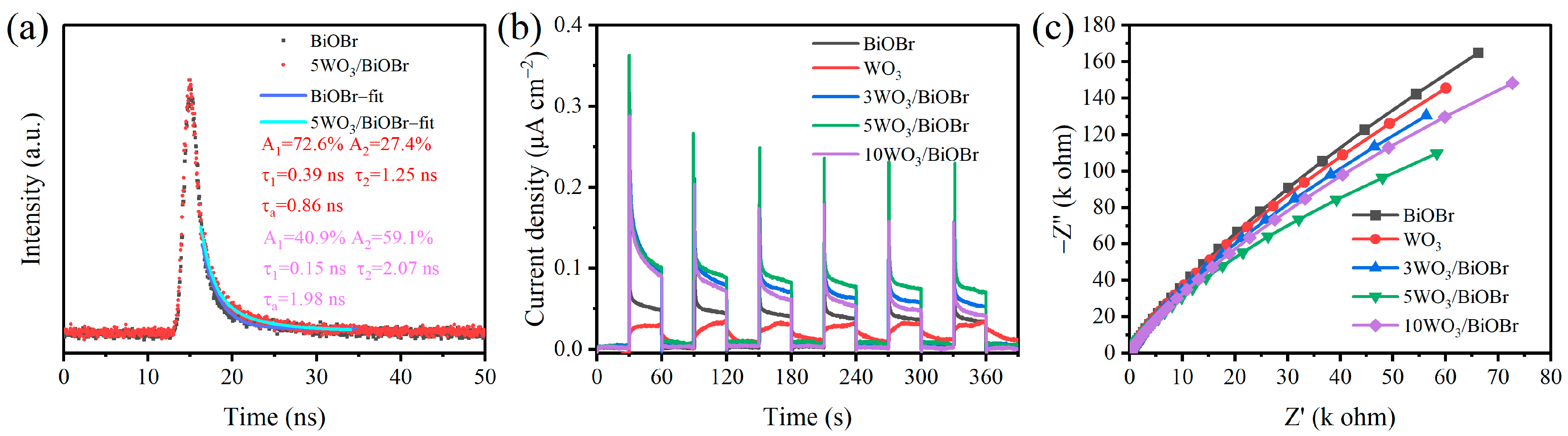
3.4. Charge Transfer and Separation

The charge transfer kinetics of BiOBr and 5WO3/BiOBr were analyzed by time-resolved photoluminescence (TRPL) spectra (Figure 5a). In general, the carrier lifetime is estimated by the photoluminescent decay time, and the average fluorescence lifetime can be calculated by Equation (1) [58,59], where A1 and A2 are pre-exponential factors and τ1 and τ2 represent the lifetimes of radiative and nonradiative transitions, respectively. Figure 5a shows that the average fluorescence lifetimes of BiOBr and 5WO3/BiOBr are 0.86 ns and 1.98 ns, respectively. The prolongation of the fluorescence lifetime in 5WO3/BiOBr indicates that the separation efficiency of photoinduced electrons and holes was enhanced after the WO3/BiOBr interface was formed [60].
τ a = A 1 τ 1 2 + A 2 τ 2 2 A 1 τ 1 + A 2 τ 2
The transient photocurrent densities were also investigated under visible light (λ ≥ 400 nm) to analyze the transfer and separation of the photogenerated charge carriers. As displayed in Figure 5b, the transient photocurrent density of 5WO3/BiOBr is higher than that of other samples, indicating that the charge separation efficiency in 5WO3/BiOBr is higher. In addition, the EIS Nyquist plots of BiOBr, WO3, and xWO3/BiOBr were obtained to explore the transfer resistance of the electrons. In general, the arc radius of the Nyquist curve is proportional to the impedance of the photocatalyst [61]. As shown in Figure 5c, the radius of 5WO3/BiOBr is smaller than that of WO3, BiOBr, 3WO3/BiOBr, and 10WO3/BiOBr, indicating that the charge transfer resistance of 5WO3/BiOBr was reduced after BiOBr coupling with WO3. Among them, 5WO3/BiOBr exhibited the highest photocurrent density and the smallest impedance arc radius, indicating the most efficient separation of photogenerated electron-hole pairs and the fastest photogenerated charge transfer on 5WO3/BiOBr. Based on the above discussion, the formation of the WO3/BiOBr heterojunction is beneficial for improving the charge separation efficiency and improving the photocatalytic performance.

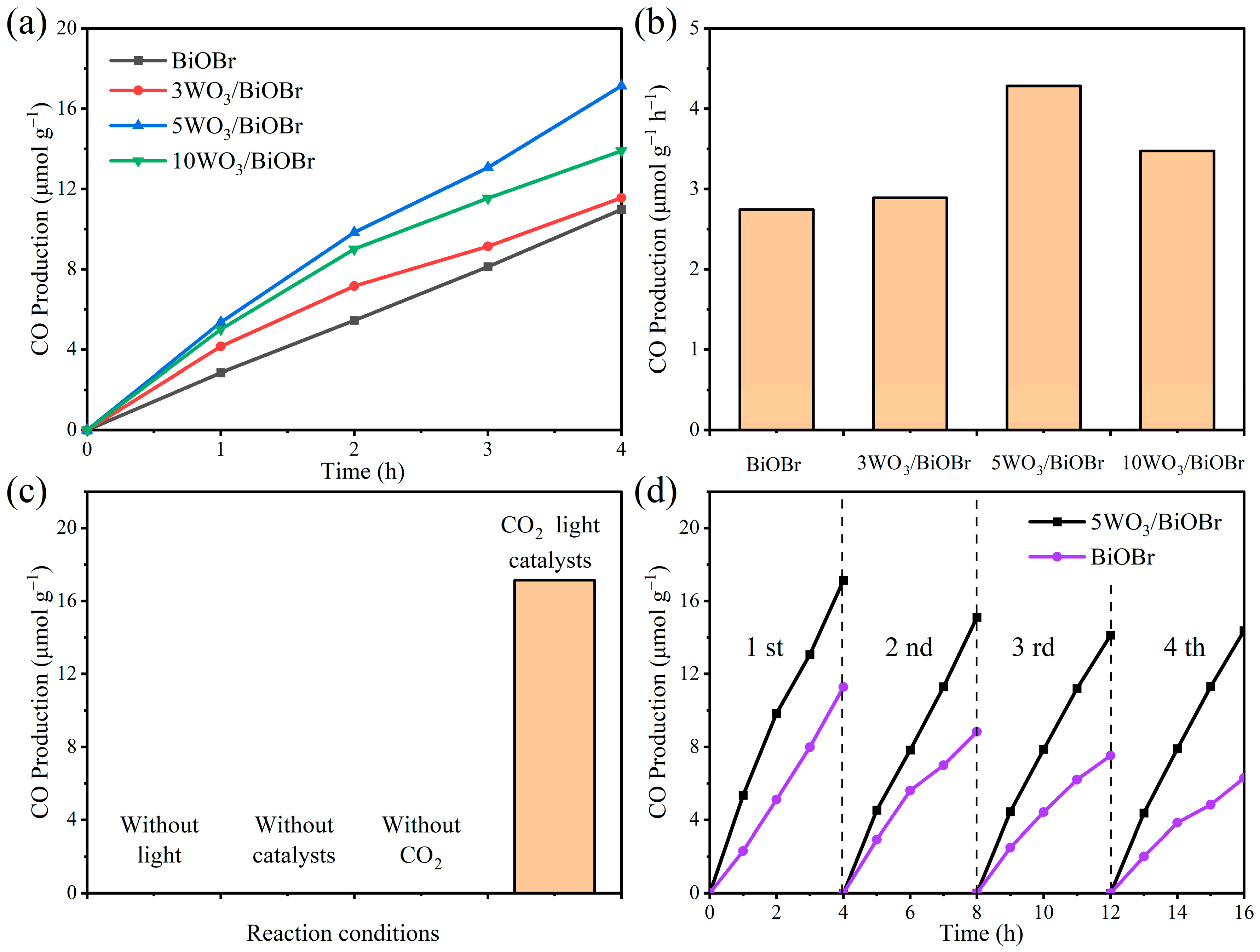
3.5. Photocatalytic CO2 Reduction

The photocatalytic CO2 reduction activity test over BiOBr and xWO3/BiOBr was carried out under visible light (Figure 6). Figure 6a,b show that the photocatalytic CO2 reduction activity of xWO3/BiOBr was greater than BiOBr. Moreover, the CO production over xWO3/BiOBr first increased and then decreased with the increase of the WO3 amount. Among them, 5WO3/BiOBr exhibited the best CO production of 17.14 μmol g−1 after 4 h reaction, which is 1.56 times greater than that of BiOBr (10.96 μmol g−1). The higher photocatalytic performance of 5WO3/BiOBr can be ascribed to the enhanced separation of photogenerated charge carriers at the WO3/BiOBr interface. To demonstrate the advantages of 5WO3/BiOBr, the photocatalytic CO2 reduction performance of the BiOBr-based photocatalysts are listed in Table S2. Compared with the other photocatalysts shown in Table S2, 5WO3/BiOBr presented satisfactory photocatalytic CO2 reduction activity. Among them, 5WO3/BiOBr exhibited the highest photocurrent density and the smallest impedance arc radius, indicating the most efficient separation of photogenerated electron-hole pairs and the fastest photogenerated charge transfer on 5WO3/BiOBr. Therefore, the CO production rate of 5WO3/BiOBr is higher than that of 3WO3/BiOBr and 10WO3/BiOBr. In addition, when the amount of WO3 is 3 wt%, a small number of heterojunctions cannot effectively promote the separation of photogenerated electrons and holes. However, when the amount of WO3 is 5 wt%, excessive WO3 will limit the light absorption capacity of BiOBr and cover the active site of CO2 reduction of BiOBr.
Controlled experiments were conducted to confirm the influence factors and C source of the product. From Figure 6c, when the photocatalytic reaction was carried out without light, a catalyst, or CO2, no CO product was detected, indicating that light, catalyst, and CO2 are the necessary conditions for photocatalytic CO2 reduction reaction. The stability of BiOBr and 5WO3/BiOBr was also studied. As shown in Figure 6d, after four cycles, the CO production over BiOBr and 5WO3/BiOBr decreased by 44.1% and 16.2%, respectively, indicating that the combination of WO3 with BiOBr can improve the stability of BiOBr during the photocatalytic reaction process. The SEM, XRD, and FT–IR of 5WO3/BiOBr were carried out to further analyze the stability of 5WO3/BiOBr (Figures S7 and S8). Figure S7 shows that no obvious change can be found in the XRD patterns and FT–IR spectra of 5WO3/BiOBr before and after the reaction, indicating that the structure of the catalyst was stable after the photocatalytic reaction. In addition, the morphology of 5WO3/BiOBr did not change before or after the reaction (Figure S8). The above results show that 5WO3/BiOBr is stable for photocatalytic CO2 reduction.

3.6. In Situ FTIR Spectra

In situ DRIFTS spectra were used to investigate the photocatalytic CO2 reduction reaction over 5WO3/BiOBr (Figure 7). Figure 7a,b show the in situ DRIFTS spectra of CO2 and H2O adsorption on BiOBr and 5WO3/BiOBr in the dark. The peaks at 1663 cm−1 and 1654 cm−1 are the signals of the water adsorbed on the catalyst surface [62]. The peaks at 1267, 1445, and 1466 cm−1 are ascribed to bicarbonate (HCO3) [63], the peaks at 1296 and 1312 cm−1 are attributed to the monolithic carbonate group (m-CO32−) [64], and the peaks at 1267 and 1363 cm−1 are assigned to bidentate carbonate (b-CO32−) [65]. In addition, the peak at 1701 cm−1 was ascribed to COOH. In general, COOH is the core intermediate for the generation of CO and CH4, and its formation time is a critical step for photocatalytic CO2 reduction to CO [66].
Figure 7c,d show the in situ DRIFTS spectra of CO2 and H2O adsorption on BiOBr and 5WO3/BiOBr under visible light irradiation. As shown in Figure 7c,d, the characteristic peaks at 1418, 1432, and 1456 cm−1 are attributed to HCO3, and the peaks in 1483 cm−1 are attributed to m-CO32−, indicating that new carbon species can be formed under light irradiation. Moreover, the concentration of the CO2 intermediates were improved with the increase of the irradiation time. Notably, the concentration of COOH was significantly improved under light irradiation, which is conducive to the photocatalytic CO2 reduction reaction.

3.7. Possible Photocatalytic Mechanism

Based on the above discussion, the reaction mechanism of photocatalytic CO2 reduction over xWO3/BiOBr composites was proposed. As displayed in Figure 8a, BiOBr acts as the reducing photocatalyst, while WO3 is an oxidizing photocatalyst, and the Fermi level of BiOBr is higher than that of WO3. When BiOBr and WO3 are in contact with each other, electrons spontaneously transfer from BiOBr to WO3 until the Fermi level reaches equilibrium. In addition, at the interface, BiOBr and WO3 are positively and negatively charged, respectively. An electron depletion region is formed at the BiOBr interface and the energy band bends upward. To the contrary, an electron accumulation zone is formed at the WO3 interface and the energy band bends downward. In this case, an internal electric field is formed at the WO3/BiOBr interfaces (Figure 8b). Under light irradiation, the electrons in the BiOBr and WO3 valence bands are excited and then jump to their conduction band. Subsequently, the electrons accumulated in the CB of WO3 combine with the holes in the VB of BiOBr (Figure 8c), which follow the S-scheme charge transfer mechanism. In addition, the electrons accumulated in the CB of BiOBr can participate in the photocatalytic CO2 reduction, while the holes in the VB of WO3 can trigger the H2O oxidation. That is, the S-scheme charge transfer mechanism not only separates photogenerated electron-holes efficiently and quickly, but also maintains the strong redox ability of WO3/BiOBr composites, which enhances the photocatalytic CO2 performance.

4. Conclusions

In summary, WO3/BiOBr S-scheme heterojunctions were synthesized for photocatalytic CO2 reduction. The optimized WO3/BiOBr heterostructures exhibited enhanced photocatalytic CO2 reduction performance without any sacrificial reagents, and the CO yield reached 17.14 μmol g−1 after reaction for 4 h, which was 1.56 times greater than that of BiOBr. The photocatalytic stability of WO3/BiOBr was also improved. The enhanced photocatalytic performance can be attributed to the S-scheme charge transfer mechanism, which effectively improves the separation efficiency of photogenerated charge carriers, thus promoting the photocatalytic CO2 reduction. This study provides new insights into the construction of efficient and stable S-scheme heterojunction photocatalysts for photocatalytic CO2 reduction.

Supplementary Materials

The following supporting information can be downloaded at: https://www.mdpi.com/article/10.3390/ma17133199/s1, Figure S1: Enlarged regions from 20° to 30° in XRD patterns of WO3, BiOBr (a), and xWO3/BiOBr (b). Figure S2: SEM images of 3WO3/BiOBr (a) and 10WO3/BiOBr (b). Figure S3: EDX spectrum of 5WO3/BiOBr. Figure S4: XPS survey spectra (a) and enlarged spectral regions from 0 eV to 100 eV (b) of BiOBr, WO3, and 5WO3/BiOBr. Figure S5: UPS spectra of WO3 (a) and BiOBr (b). Figure S6: Mott-Schottky plots of BiOBr (a) and WO3 (b) at the frequencies of 1000 Hz, 1500 Hz, and 2000 Hz. Figure S7: XRD patterns (a) and FT-IR spectra (b) of 5WO3/BiOBr before and after reaction. Figure S8: SEM images of 5WO3/BiOBr before (a) and after (b) reaction. Table S1: Specific surface area and average pore size of the samples. Table S2: Comparison of photocatalytic CO2 reduction performance over the BiOBr-based photocatalysts. References [45,55,66,67,68,69,70] are cited in the Supplementary Materials.

Author Contributions

Conceptualization, T.S.; Methodology, L.C. and X.X.; Formal analysis, L.C. and T.S.; Investigation, C.L., X.L. and L.C.; Resources, T.S. and H.J.; Data curation, C.L.; Writing—original draft, C.L.; Writing—review & editing, X.X., Z.Q., H.J. and T.S.; Supervision, T.S.; Funding acquisition, Z.Q. and T.S. All authors have read and agreed to the published version of the manuscript.

Funding

This work was supported by the National Natural Science Foundation of China (22208065), Guangxi Natural Science Foundation (2022GXNSFBA035483), National Natural Science Foundation of China (22078074), Opening Project of Guangxi Key Laboratory of Petrochemical Resource Processing and Process Intensification Technology (2023K012), and Special Funding for “Guangxi Bagui Scholars”.

Institutional Review Board Statement

Not applicable.

Informed Consent Statement

Not applicable.

Data Availability Statement

The original contributions presented in the study are included in the article/Supplementary Material, further inquiries can be directed to the corresponding author.

Conflicts of Interest

The authors declare no conflicts of interest.

References

  1. Yang, H.; Dang, Y.; Cui, X.; Bu, X.; Li, J.; Li, S.; Sun, Y.; Gao, P. Selective synthesis of olefins via CO2 hydrogenation over transition-metal-doped iron-based catalysts. Appl. Catal. B 2023, 321, 122050. [Google Scholar] [CrossRef]
  2. He, F.; Zhu, B.; Cheng, B.; Yu, J.; Ho, W.; Macyk, W. 2D/2D/0D TiO2/C3N4/Ti3C2 MXene composite S-scheme photocatalyst with enhanced CO2 reduction activity. Appl. Catal. B 2020, 272, 119006. [Google Scholar] [CrossRef]
  3. Wang, S.; Han, X.; Zhang, Y.; Tian, N.; Ma, T.; Huang, H. Inside-and-Out Semiconductor Engineering for CO2 Photoreduction: From Recent Advances to New Trends. Small Struct. 2020, 2, 2000061. [Google Scholar] [CrossRef]
  4. Liang, J.; Yu, H.; Shi, J.; Li, B.; Wu, L.; Wang, M. Dislocated Bilayer MOF Enables High-Selectivity Photocatalytic Reduction of CO2 to CO. Adv. Mater. 2023, 35, 2209814. [Google Scholar] [CrossRef] [PubMed]
  5. Yang, M.; Wang, P.; Li, Y.; Tang, S.; Lin, X.; Zhang, H.; Zhu, Z.; Chen, F. Graphene aerogel-based NiAl-LDH/g-C3N4 with ultratight sheet-sheet heterojunction for excellent visible-light photocatalytic activity of CO2 reduction. Appl. Catal. B 2022, 306, 121065. [Google Scholar] [CrossRef]
  6. Chen, L.; Li, H.; Li, H.; Li, H.; Qi, W.; Zhang, Q.; Zhu, J.; Zhao, P.; Yang, S. Accelerating photogenerated charge kinetics via the g-C3N4 Schottky junction for enhanced visible-light-driven CO2 reduction. Appl. Catal. B 2022, 318, 121863. [Google Scholar] [CrossRef]
  7. Jo, Y.; Kim, C.; Moon, G.-H.; Lee, J.; An, T.; Choi, W. Activation of peroxymonosulfate on visible light irradiated TiO2 via a charge transfer complex path. Chem. Eng. J. 2018, 346, 249–257. [Google Scholar] [CrossRef]
  8. Xu, F.; Meng, K.; Cheng, B.; Wang, S.; Xu, J.; Yu, J. Unique S-scheme heterojunctions in self-assembled TiO2/CsPbBr3 hybrids for CO2 photoreduction. Nat. Commun. 2020, 11, 4613. [Google Scholar] [CrossRef]
  9. Li, L.; Ma, D.; Xu, Q.; Huang, S. Constructing hierarchical ZnIn2S4/g-C3N4 S-scheme heterojunction for boosted CO2 photoreduction performance. Chem. Eng. J. 2022, 437, 135153. [Google Scholar] [CrossRef]
  10. Liapun, V.; Hanif, M.B.; Sihor, M.; Vislocka, X.; Pandiaraj, S.; Unnikrishnan, V.K.; Thirunavukkarasu, G.K.; Edelmannová, M.F.; Reli, M.; Monfort, O.; et al. Versatile application of BiVO4/TiO2 S-scheme photocatalyst: Photocatalytic CO2 and Cr(VI) reduction. Chemosphere 2023, 337, 139397. [Google Scholar] [CrossRef]
  11. Yue, X.; Cheng, L.; Fan, J.; Xiang, Q. 2D/2D BiVO4/CsPbBr3 S-scheme heterojunction for photocatalytic CO2 reduction: Insights into structure regulation and Fermi level modulation. Appl. Catal. B 2022, 304, 120979. [Google Scholar] [CrossRef]
  12. Ye, L.; Deng, Y.; Wang, L.; Xie, H.; Su, F. Bismuth-Based Photocatalysts for Solar Photocatalytic Carbon Dioxide Conversion. ChemSusChem 2019, 12, 3671–3701. [Google Scholar] [CrossRef] [PubMed]
  13. Zhao, X.; Xia, Y.; Wang, X.; Wen, N.; Li, H.; Jiao, X.; Chen, D. Promoted photocarriers separation in atomically thin BiOCl/Bi2WO6 heterostructure for solar-driven photocatalytic CO2 reduction. Chem. Eng. J. 2022, 449, 137874. [Google Scholar] [CrossRef]
  14. Zhao, J.; Miao, Z.; Zhang, Y.; Wen, G.; Liu, L.; Wang, X.; Cao, X.; Wang, B. Oxygen vacancy-rich hierarchical BiOBr hollow microspheres with dramatic CO2 photoreduction activity. J. Colloid Interface Sci. 2021, 593, 231–243. [Google Scholar] [CrossRef]
  15. Jiang, L.; Li, J.; Li, Y.; Wu, X.; Zhang, G. Promoted charge separation from nickel intervening in [Bi2O2]2+ layers of Bi2O2S crystals for enhanced photocatalytic CO2 conversion. Appl. Catal. B 2021, 294, 120249. [Google Scholar] [CrossRef]
  16. Meng, L.; Qu, Y.; Jing, L. Recent advances in BiOBr-based photocatalysts for environmental remediation. Chinese Chem. Lett. 2021, 32, 3265–3276. [Google Scholar] [CrossRef]
  17. Wu, J.; Li, X.; Shi, W.; Ling, P.; Sun, Y.; Jiao, X.; Gao, S.; Liang, L.; Xu, J.; Yan, W.; et al. Efficient Visible-Light-Driven CO2 Reduction Mediated by Defect-Engineered BiOBr Atomic Layers. Angew Chem. Int. 2018, 57, 8719–8723. [Google Scholar] [CrossRef] [PubMed]
  18. Zhang, B.; Zhang, M.; Zhang, L.; Bingham, P.A.; Tanaka, M.; Li, W.; Kubuki, S. BiOBr/MoS2 catalyst as heterogenous peroxymonosulfate activator toward organic pollutant removal: Energy band alignment and mechanism insight. J. Colloid Interface Sci. 2021, 594, 635–649. [Google Scholar] [CrossRef]
  19. Li, X.; Li, K.; Ding, D.; Yan, J.; Wang, C.; Carabineiro, S.A.C.; Liu, Y.; Lv, K. Effect of oxygen vacancies on the photocatalytic activity of flower-like BiOBr microspheres towards NO oxidation and CO2 reduction. Sep. Purif. Technol. 2023, 309, 123054. [Google Scholar] [CrossRef]
  20. Wang, K.; Cheng, M.; Xia, F.; Cao, N.; Zhang, F.; Ni, W.; Yue, X.; Yan, K.; He, Y.; Shi, Y.; et al. Atomically Dispersed Electron Traps in Cu Doped BiOBr Boosting CO2 Reduction to Methanol by Pure H2O. Small 2023, 19, 2207581. [Google Scholar] [CrossRef]
  21. Wang, Z.; Cheng, B.; Zhang, L.; Yu, J.; Tan, H. BiOBr/NiO S-Scheme Heterojunction Photocatalyst for CO2 Photoreduction. Sol. Rrl 2021, 6, 2100587. [Google Scholar] [CrossRef]
  22. Yan, C.; Xu, M.; Cao, W.; Chen, Q.; Song, X.; Huo, P.; Zhou, W.; Wang, H. Fabricated S-scheme BiOBr/Cu2O heterojunction photocatalyst for adjusting conversion of CO2 to CH4. J. Environ. Chem. Eng. 2023, 11, 111479. [Google Scholar] [CrossRef]
  23. Zhang, T.; Maihemllti, M.; Okitsu, K.; Talifur, D.; Tursun, Y.; Abulizi, A. In situ self-assembled S-scheme BiOBr/pCN hybrid with enhanced photocatalytic activity for organic pollutant degradation and CO2 reduction. Appl. Surf. Sci. 2021, 556, 149828. [Google Scholar] [CrossRef]
  24. Meng, A.; Cheng, B.; Tan, H.; Fan, J.; Su, C.; Yu, J. TiO2/polydopamine S-scheme heterojunction photocatalyst with enhanced CO2-reduction selectivity. Appl. Catal. B 2021, 289, 120039. [Google Scholar] [CrossRef]
  25. Rana, S.; Kumar, A.; Sharma, G.; Dhiman, P.; Garcia-Penas, A.; Stadler, F.J. Recent advances in perovskite-based Z-scheme and S-scheme heterojunctions for photocatalytic CO2 reduction. Chemosphere 2023, 339, 139765. [Google Scholar] [CrossRef] [PubMed]
  26. Wang, L.; Zhu, B.; Zhang, J.; Ghasemi, J.B.; Mousavi, M.; Yu, J. S-scheme heterojunction photocatalysts for CO2 reduction. Matter 2022, 5, 4187–4211. [Google Scholar] [CrossRef]
  27. Li, X.; Song, X.; Ma, C.; Cheng, Y.; Shen, D.; Zhang, S.; Liu, W.; Huo, P.; Wang, H. Direct Z-Scheme WO3/Graphitic Carbon Nitride Nanocomposites for the Photoreduction of CO2. ACS Appl. Nano Mater. 2020, 3, 1298–1306. [Google Scholar] [CrossRef]
  28. Sun, Y.; Han, Y.; Song, X.; Huang, B.; Ma, X.; Xing, R. CdS/WO3 S-scheme heterojunction with improved photocatalytic CO2 reduction activity. J. Photochem. Photobiol. B 2022, 233, 112480. [Google Scholar] [CrossRef] [PubMed]
  29. Jiang, X.; Ding, Y.; Zheng, S.; Ye, Y.; Li, Z.; Xu, L. In-Situ Generated CsPbBr3 Nanocrystalson O-Defective WO3 for Photocatalytic CO2 Reduction. ChemSusChem 2022, 15, e202102295. [Google Scholar] [CrossRef]
  30. Jiang, R.; Zhu, H.Y.; Li, J.B.; Fu, F.Q.; Yao, J.; Jiang, S.T.; Zeng, G.M. Fabrication of novel magnetically separable BiOBr/CoFe2O4 microspheres and its application in the efficient removal of dye from aqueous phase by an environment-friendly and economical approach. Appl. Surf. Sci. 2016, 364, 604–612. [Google Scholar] [CrossRef]
  31. Shan, W.; Hu, Y.; Bai, Z.; Zheng, M.; Wei, C. In situ preparation of g-C3N4/bismuth-based oxide nanocomposites with enhanced photocatalytic activity. Appl. Catal. B Environ. 2016, 188, 1–12. [Google Scholar] [CrossRef]
  32. Zhang, M.; Lai, C.; Li, B.; Huang, D.; Zeng, G.; Xu, P.; Qin, L.; Liu, S.; Liu, X.; Yi, H.; et al. Rational design 2D/2D BiOBr/CDs/g-C3N4 Z-scheme heterojunction photocatalyst with carbon dots as solid-state electron mediators for enhanced visible and NIR photocatalytic activity: Kinetics, intermediates, and mechanism insight. J. Cata 2019, 369, 469–481. [Google Scholar] [CrossRef]
  33. Gao, Z.; Yao, B.; Yang, F.; Xu, T.; He, Y. Preparation of BiOBr-Bi heterojunction composites with enhanced photocatalytic properties on BiOBr surface by in-situ reduction. Mat. Sci. Semiconr. Proc. 2020, 108, 104882. [Google Scholar] [CrossRef]
  34. Li, W.; Zou, Y.; Geng, X.; Xiao, F.; An, G.; Wang, D. Constructing highly catalytic oxidation over BiOBr-based hierarchical microspheres: Importance of redox potential of doped cations. Mol. Cat. 2017, 438, 19–29. [Google Scholar] [CrossRef]
  35. Thiyagarajan, K.; Muralidharan, M.; Sivakumar, K. Defects Induced Magnetism in WO3 and Reduced Graphene Oxide-WO3 Nanocomposites. J. Supercond. Nov. Magn. 2017, 31, 117–125. [Google Scholar] [CrossRef]
  36. Du, C.; Nie, S.; Feng, W.; Zhang, J.; Qi, M.; Liang, Y.; Wu, Y.; Feng, J.; Dong, S.; Liu, H.; et al. Hydroxyl regulating effect on surface structure of BiOBr photocatalyst toward high-efficiency degradation performance. Chemosphere 2022, 287, 132246. [Google Scholar] [CrossRef] [PubMed]
  37. Tang, Q.Y.; Yang, M.J.; Yang, S.Y.; Xu, Y.H. Enhanced photocatalytic degradation of glyphosate over 2D CoS/BiOBr heterojunctions under visible light irradiation. J. Hazard. Mater. 2021, 407, 124798. [Google Scholar] [CrossRef] [PubMed]
  38. Tao, W.; Tang, Q.; Hu, J.; Wang, Z.; Jiang, B.; Xiao, Y.; Song, R.; Guo, S. Construction of a hierarchical BiOBr/C3N4 S-scheme heterojunction for selective photocatalytic CO2 reduction towards CO. J. Mater. Chem. A 2023, 11, 24999–25007. [Google Scholar] [CrossRef]
  39. Zhang, K.; Zhang, Y.; Zhang, D.; Liu, C.; Zhou, X.; Yang, H.; Qu, J.; He, D. Efficient photocatalytic water disinfection by a novel BP/BiOBr S-scheme heterojunction photocatalyst. Chem. Eng. J. 2023, 468, 143581. [Google Scholar] [CrossRef]
  40. Li, S.; Hu, S.; Jiang, W.; Zhang, J.; Xu, K.; Wang, Z. In situ construction of WO3 nanoparticles decorated Bi2MoO6 microspheres for boosting photocatalytic degradation of refractory pollutants. J. Colloid. Interf. Sci. 2019, 556, 335–344. [Google Scholar] [CrossRef]
  41. Xie, J.; Lu, Z.; Feng, Y.; Huang, J.; Hu, J.; Hao, A.; Ca, Y. A small organic molecule strategy for remedying oxygen vacancies by bismuth defects in BiOBr nanosheet with excellent photocatalytic CO2 reduction. Nano Res. 2024, 17, 297–306. [Google Scholar] [CrossRef]
  42. Jin, Y.; Li, F.; Li, T.; Xing, X.; Fan, W.; Zhang, L.; Hu, C. Enhanced internal electric field in S-doped BiOBr for intercalation, adsorption and degradation of ciprofloxacin by photoinitiation. Appl. Catal. B 2022, 302, 120824. [Google Scholar] [CrossRef]
  43. Hao, J.; Zhang, Y.; Zhang, L.; Shen, J.; Meng, L.; Wang, X. Restructuring surface frustrated Lewis acid-base pairs of BiOBr through isomorphous Sn doping for boosting photocatalytic CO2 reduction. Chem. Eng. J. 2023, 464, 142536. [Google Scholar] [CrossRef]
  44. Albukhari, S.M.; Al-Hajji, L.A.; Ismail, A.A. Minimizing CO2 emissions by photocatalytic CO2 reduction to CH3OH over Li2MnO3/WO3 heterostructures under visible illumination. Environ. Res. 2024, 241, 117573. [Google Scholar] [CrossRef] [PubMed]
  45. Qin, W.; Yang, Q.; Ye, H.; Xie, Y.; Shen, Z.; Guo, Y.; Deng, Y.; Ling, Y.; Yu, J.; Luo, G.; et al. Novel 2D/2D BiOBr/Zn(OH)2 photocatalysts for efficient photoreduction CO2. Sep. Purif. Technol. 2023, 306, 122721. [Google Scholar] [CrossRef]
  46. Yaseen, M.; Jiang, H.; Li, J.; Yu, X.; Ashfaq Ahmad, M.; Nauman Ali, R.; Wang, L.; Yang, J.; Liu, Q. Synergistic effect of Z-scheme and oxygen vacancy of CeO2/WO3 heterojunction for enhanced CO2 reduction activity. Appl. Surf. Sci. 2023, 631, 157360. [Google Scholar] [CrossRef]
  47. Liu, Y.; Guo, J.-g.; Wang, Y.; Hao, Y.-j.; Liu, R.-h.; Li, F.-t. One-step synthesis of defected Bi2Al4O9/β-Bi2O3 heterojunctions for photocatalytic reduction of CO2 to CO. Green Energy Environ. 2021, 6, 244–252. [Google Scholar] [CrossRef]
  48. Xiao, Y.; Maimaitizi, H.; Okitsu, K.; Tursun, Y.; Abulizi, A. Sonochemical Fabrication of S-scheme Hierarchical CdS/BiOBr Heterojunction Photocatalyst with High Performance for Carbon Dioxide Reduction. Part. Part. Syst. Charact. 2022, 39, 2200019. [Google Scholar] [CrossRef]
  49. Chico-Vecino, M.; Murillo-Sierra, J.C.; Pino-Sandoval, D.A.; Hinojosa-Reyes, L.; Maya-Treviño, M.L.; Contreras, D.; Hernández-Ramírez, A. Preparation of WO3/In2O3 heterojunctions and their performance on the CO2 photocatalytic conversion in a continuous flow reactor. J. Environ. Chem. Eng. 2023, 11, 110372. [Google Scholar] [CrossRef]
  50. Huang, W.; Hua, X.; Zhao, Y.; Li, K.; Tang, L.; Zhou, M.; Cai, Z. Enhancement of visible-light-driven photocatalytic performance of BiOBr nanosheets by Co2+ doping. J. Mater. Sci. Mater. Electron. 2019, 30, 14967–14976. [Google Scholar] [CrossRef]
  51. Ma, Y.; Li, J.; Cai, J.; Zhong, L.; Lang, Y.; Ma, Q. Z-scheme g-C3N4/ZnS heterojunction photocatalyst: One-pot synthesis, interfacial structure regulation, and improved photocatalysis activity for bisphenol A. Colloids Surf. A 2022, 653, 130027. [Google Scholar] [CrossRef]
  52. Kong, W.; Zhu, D.; Zhang, Y.; Luo, R.; Ma, J.; Lei, J.; Ju, H. Electron Donor Coordinated Metal-Organic Framework to Enhance Photoelectrochemical Performance. Angew. Chem. Int. 2023, 62, 202308514. [Google Scholar] [CrossRef] [PubMed]
  53. Radha, R.; Kulangara, R.V.; Elaiyappillai, E.; Sridevi, J.; Balakumar, S. Modulation in the Band Dispersion of Bi2WO6 Nanocrsytals Using the Electronegativity of Transition Elements for Enhanced Visible Light Photocatalysis. Cryst. Growth Des. 2019, 19, 6224–6238. [Google Scholar] [CrossRef]
  54. Yu, T.; Liu, Q.; Zhu, Z.; Wu, W.; Liu, L.; Zhang, J.; Gao, C.; Yang, T. Construction of a photocatalytic fuel cell using a novel Z-scheme MoS2/rGO/Bi2S3 as electrode degraded antibiotic wastewater. Sep. Purif. Technol. 2021, 277, 119276. [Google Scholar] [CrossRef]
  55. Gaopeng, L.; Lin, W.; Bin, W.; Xingwang, Z.; Jinman, Y.; Pengjun, L.; Wenshuai, Z.; Ziran, C.; Jiexiang, X. Synchronous activation of Ag nanoparticles and BiOBr for boosting solar-driven CO2 reduction. Chin. Chem. Lett. 2023, 34, 107962. [Google Scholar]
  56. Sun, M.; Zhu, C.; Wei, S.; Chen, L.; Ji, H.; Su, T.; Qin, Z. Phosphorus-Doped Hollow Tubular g-C3N4 for Enhanced Photocatalytic CO2 Reduction. Materials 2023, 16, 6665. [Google Scholar] [CrossRef] [PubMed]
  57. Juntrapirom, S.; Anuchai, S.; Thongsook, O.; Pornsuwan, S.; Meepowpan, P.; Thavornyutikarn, P.; Phanichphant, S.; Tantraviwat, D.; Inceesungvorn, B. Photocatalytic activity enhancement of g-C3N4/BiOBr in selective transformation of primary amines to imines and its reaction mechanism. Chem. Eng. J. 2020, 394, 124934. [Google Scholar] [CrossRef]
  58. Chen, K.; Wang, X.; Li, Q.; Feng, Y.-N.; Chen, F.-F.; Yu, Y. Spatial distribution of ZnIn2S4 nanosheets on g-C3N4 microtubes promotes photocatalytic CO2 reduction. Chem. Eng. J. 2021, 418, 129476. [Google Scholar] [CrossRef]
  59. Guo, H.; Wan, S.; Wang, Y.; Ma, W.; Zhong, Q.; Ding, J. Enhanced photocatalytic CO2 reduction over direct Z-scheme NiTiO3/g-C3N4 nanocomposite promoted by efficient interfacial charge transfer. Chem. Eng. J. 2021, 412, 128646. [Google Scholar] [CrossRef]
  60. Zhao, M.; Qin, J.; Wang, N.; Zhang, Y.; Cui, H. Reconstruction of surface oxygen vacancy for boosting CO2 photoreduction mediated by BiOBr/CdS heterojunction. Sep. Purif. Technol. 2024, 329, 125179. [Google Scholar] [CrossRef]
  61. Wu, J.; Xie, Y.; Ling, Y.; Si, J.; Li, X.; Wang, J.; Ye, H.; Zhao, J.; Li, S.; Zhao, Q.; et al. One-step synthesis and Gd3+ decoration of BiOBr microspheres consisting of nanosheets toward improving photocatalytic reduction of CO2 into hydrocarbon fuel. Chem. Eng. J. 2020, 400, 125944. [Google Scholar] [CrossRef]
  62. Yin, S.; Zhao, X.; Jiang, E.; Yan, Y.; Zhou, P.; Huo, P. Boosting water decomposition by sulfur vacancies for efficient CO2 photoreduction. Energy Environ. Sci. 2022, 15, 1556–1562. [Google Scholar] [CrossRef]
  63. Meng, J.; Duan, Y.; Jing, S.; Ma, J.; Wang, K.; Zhou, K.; Ban, C.; Wang, Y.; Hu, B.; Yu, D.; et al. Facet junction of BiOBr nanosheets boosting spatial charge separation for CO2 photoreduction. Nano Energy 2022, 92, 106671. [Google Scholar] [CrossRef]
  64. Wang, B.; Zhao, J.; Chen, H.; Weng, Y.-X.; Tang, H.; Chen, Z.; Zhu, W.; She, Y.; Xia, J.; Li, H. Unique Z-scheme carbonized polymer dots/Bi4O5Br2 hybrids for efficiently boosting photocatalytic CO2 reduction. Appl. Catal. B Environ. 2021, 293, 120182. [Google Scholar] [CrossRef]
  65. Bai, P.; Zhao, Y.; Li, Y. Efficient photocatalytic CO2 reduction coupled with selective styrene oxidation over a modified g-C3N4/BiOBr composite with high atom economy. Green Chem. 2024, 26, 2290–2299. [Google Scholar] [CrossRef]
  66. Lin, W.; Gaopeng, L.; Bin, W.; Xin, C.; Chongtai, W.; Zixia, L.; Jiexiang, X.; Huaming, L. Oxygen Vacancies Engineering–Mediated BiOBr Atomic Layers for Boosting Visible Light-Driven Photocatalytic CO2 Reduction. Solar Rrl 2020, 5, 2000480. [Google Scholar]
  67. Guan, C.; Hou, T.; Nie, W.; Zhang, Q.; Duan, L.; Zhao, X. Enhanced photocatalytic reduction of CO2 on BiOBr under synergistic effect of Zn doping and induced oxygen vacancy generation. J. Colloid Interface Sci. 2023, 633, 177–188. [Google Scholar] [CrossRef] [PubMed]
  68. Jiayu, Z.; Yupei, L.; Xiaojing, W.; Jun, Z.; Yinsu, W.; Fatang, L. Simultaneous Phosphorylation and Bi Modification of BiOBr for Promoting Photocatalytic CO2 Reduction. ACS Sustain. Chem. Eng. 2019, 7, 14953–14961. [Google Scholar]
  69. Xin, F.; ChuYa, W.; Longpeng, Z.; Qi, Z.; Hengdeng, Z.; Qi, W.; Guangcan, Z. Efficient visible-light-driven CO2 reduction mediated by novel Au-doped BiOBr nanosheets. J. Environ. Chem. Eng. 2023, 11, 109986. [Google Scholar]
  70. Ying, K.X.; Cathie, L.W.P.; WeeJun, O.; SiangPiao, C.; Rahman, M.A. Oxygen-Deficient BiOBr as a Highly Stable Photocatalyst for Efficient CO2 Reduction into Renewable Carbon-Neutral Fuels. ChemCatChem 2016, 8, 3074–3081. [Google Scholar]
Figure 1. XRD patterns (a), FT–IR spectra (b), N2 adsorption–desorption isotherms (c), and pore size distributions (d) of BiOBr, WO3, and xWO3/BiOBr.
Materials 17 03199 g001
Figure 2. SEM images of BiOBr (a), WO3 (b), and 5WO3/BiOBr (c). TEM and HRTEM images (df), HAADF image (g), and corresponding EDX mapping profiles of Bi (h), Br (i), O (j), and W (k) of 5WO3/BiOBr.
Materials 17 03199 g002
Figure 3. XPS spectra of Bi 4f (a), Br 3d (b), O 1 s (c), and W 4f (d) in BiOBr, WO3, and 5WO3/BiOBr.
Materials 17 03199 g003
Figure 4. UV–Vis DRS of BiOBr, WO3, and xWO3/BiOBr (a), band gap of BiOBr and WO3 (b), and UPS spectra (c) and band structure (d) of WO3 and BiOBr.
Materials 17 03199 g004
Figure 5. TRPL spectra of BiOBr and 5WO3/BiOBr (a), transient photocurrent density (b), and EIS Nyqui st plots (c) of BiOBr, WO3, and xWO3/BiOBr.
Materials 17 03199 g005
Figure 6. Time course of photocatalytic CO2 reduction over BiOBr and xWO3/BiOBr (a,b), photocatalytic CO2 reduction over 5WO3/BiOBr under different conditions (c), and cycle test of BiOBr and 5WO3/BiOBr photocatalytic CO2 reduction to CO (d).
Materials 17 03199 g006
Figure 7. In situ DRIFTS spectra of CO2 and H2O adsorption on BiOBr (a) and 5WO3/BiOBr (b) in the dark. In situ DRIFTS spectra of CO2 and H2O adsorption on BiOBr (c) and 5WO3/BiOBr (d) under light irradiation.
Materials 17 03199 g007
Figure 8. Band energy positions of WO3 and BiOBr before (a) and after (b) contact, S-scheme charge transfer mechanism in WO3/BiOBr composites under light irradiation (c).
Materials 17 03199 g008
Disclaimer/Publisher’s Note: The statements, opinions and data contained in all publications are solely those of the individual author(s) and contributor(s) and not of MDPI and/or the editor(s). MDPI and/or the editor(s) disclaim responsibility for any injury to people or property resulting from any ideas, methods, instructions or products referred to in the content.

