

On Strain-Hardening Behavior and Ductility of Laser Powder Bed-Fused Ti6Al4V Alloy Heat-Treated above and below the β-Transus


Abstract
:1. Introduction
- Decomposition of the brittle α′-martensite laths into α + β phase during the exposure at temperatures below the β-transus, i.e., during stress relief, annealing, and sub-transus solution heat treatment (SHT). Ductility improves with increasing heat-treatment temperatures.
- Recrystallization of the columnar β-grains during the exposure at solution temperatures (above the β-transus) and the formation of a desired α + β microstructure by controlling the cooling pathway from the β-region to the room temperature.
- Annealing heat treatments at 704 and 740 °C;
- Super-transus SHT at 1050 °C.
2. Materials and Methods
3. Results
- The fine α + β laths and colonies;
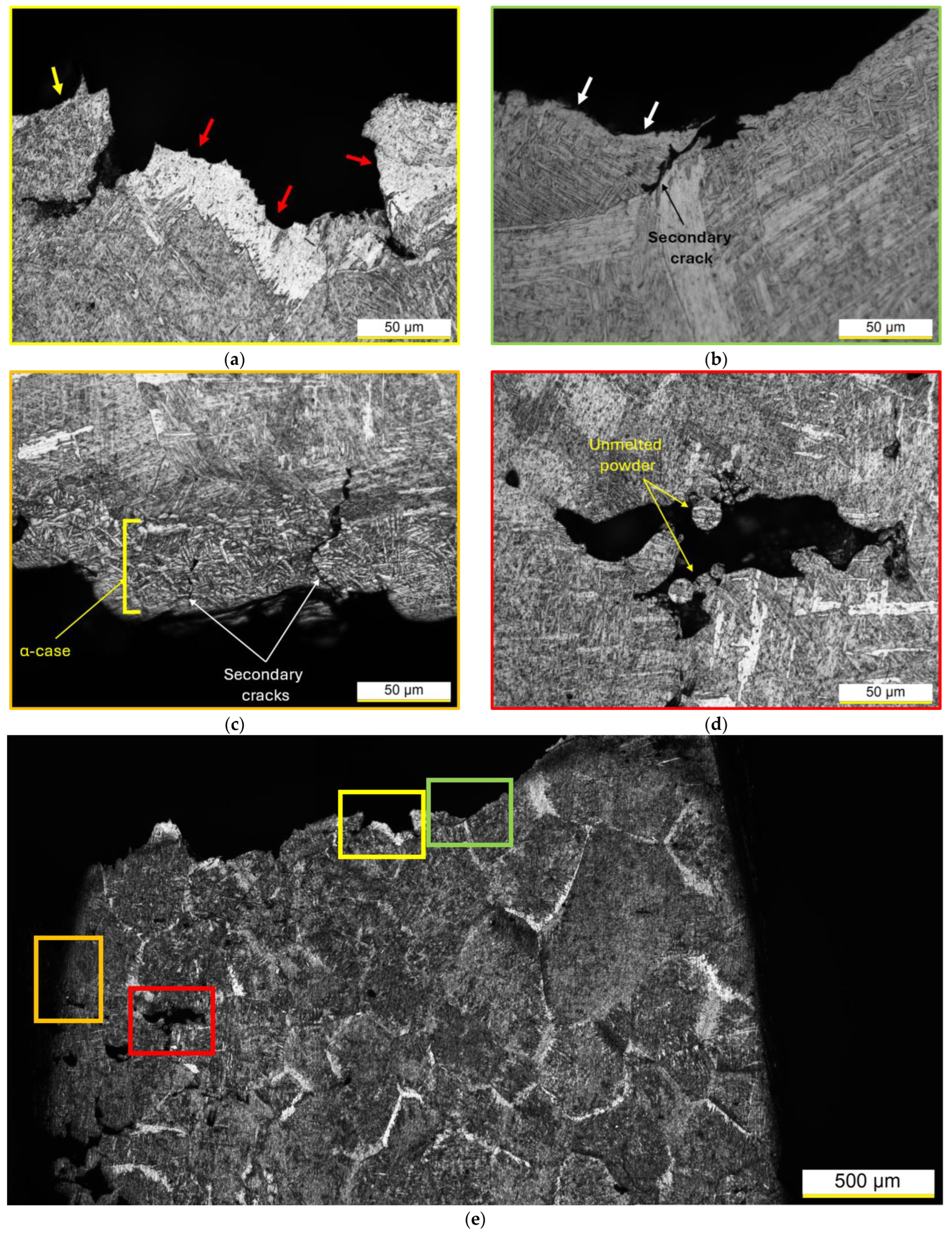
- The α-case layer (as will later be discussed).
4. Conclusions
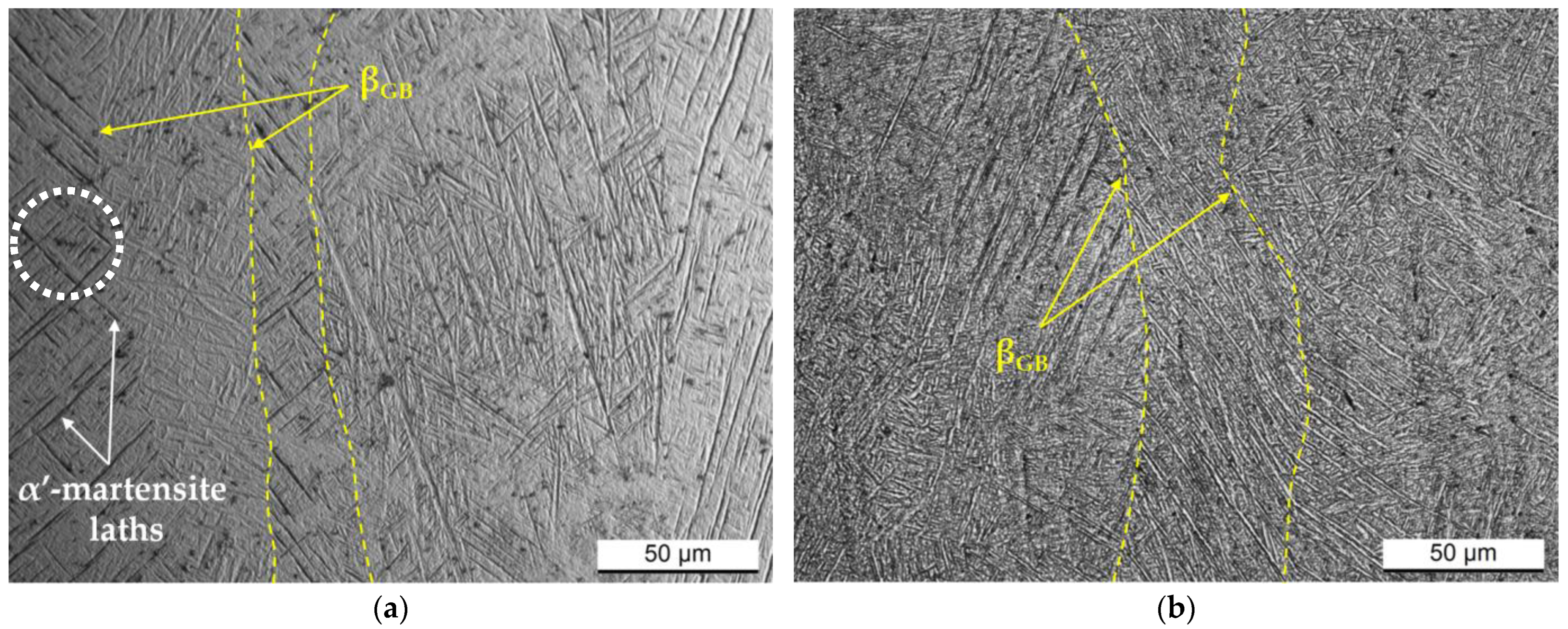
- The microstructure of the annealed Ti6Al4V samples exhibits retained columnar β-grains containing α-phase laths arranged in a cross-hatched structure. When treatment temperature increases from 704 to 740 °C, α-phase width increases by about +30%.
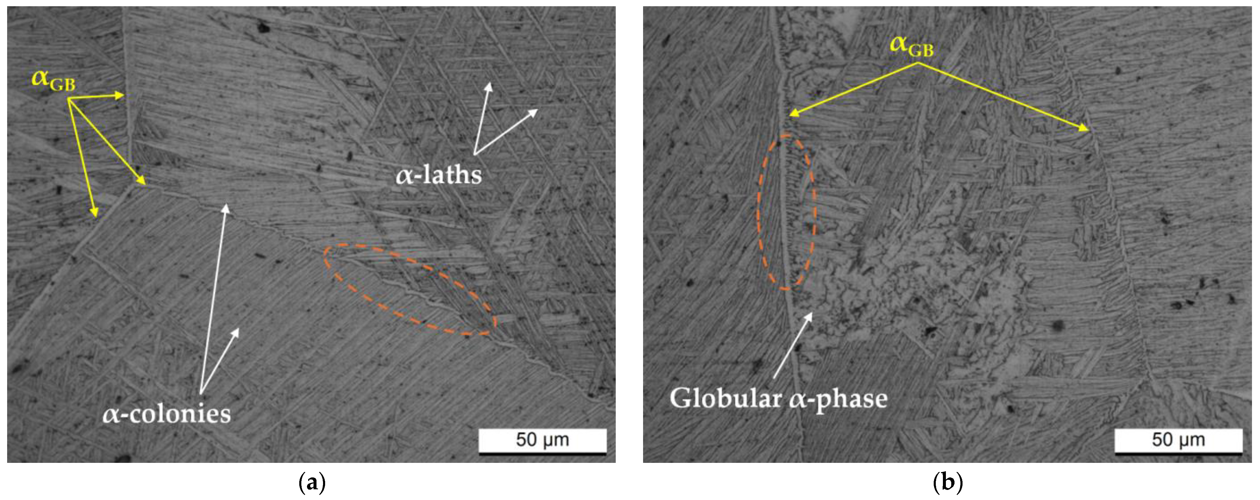
- The columnar β-grains recrystallize into equiaxed β-grains during the exposure at 1050 °C, and subsequent argon cooling forms an α + β microstructure with several morphologies: (i) colonies, (ii) Widmanstätten structure, and (iii) globular.
- Due to the rise in heat-treatment temperature, both yield and ultimate tensile strengths decreased by about—16% and—12%, respectively. However, elongation values did not show significant improvement. All analyzed samples exhibited excellent uniform elongations (>7.8%), which increased from Ti64 samples annealed at 704 °C to those solution-heat-treated at 1050 °C, along with necking instability.
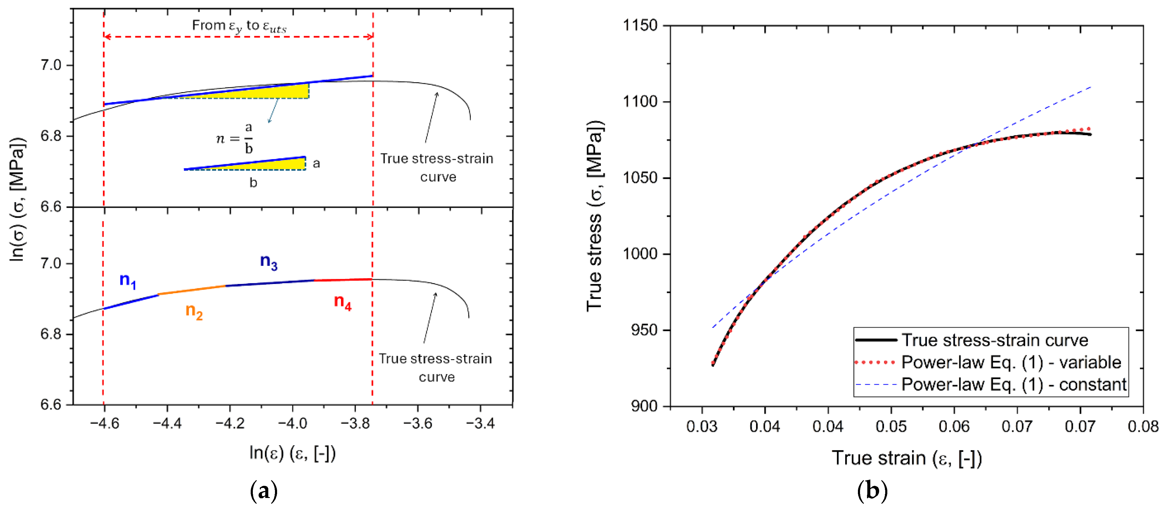
- The equality between the uniform elongations obtained by the Considère criterion and the indicates that constant and values must be considered.
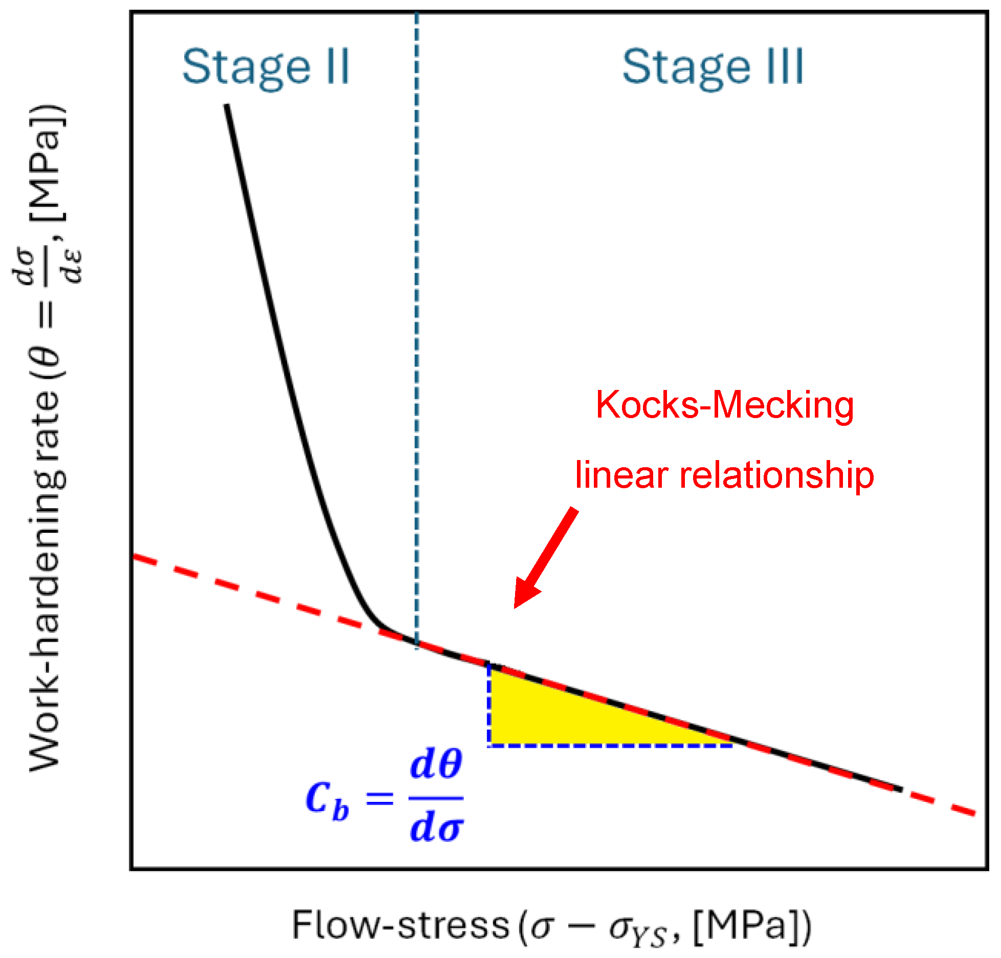
- Annealed samples show higher ratios than those exhibited by the Ti6Al4V samples with recrystallized microstructure. The consequent lower work-hardening capacity values promote low work-hardening of the necking region. Thereby, the recrystallized microstructure shows both lower work-hardening rates in Stage II and lower softening values (i.e., dynamic recovery). This is reflected in the highest hardness increment from the undeformed region obtained during the plastic deformation.
- Despite the anisotropy conferred by the build orientations, they did not significantly influence the work-hardening behavior.
Author Contributions
Funding
Institutional Review Board Statement
Informed Consent Statement
Data Availability Statement
Conflicts of Interest
References
- Donachie, M.J. Titanium: A Technical Guide, 2nd ed.; ASM International Materials Park: Novelty, OH, USA, 2000. [Google Scholar]
- Carson, C. Heat Treating of Titanium and Titanium Alloys. In Heat Treating of Nonferrous Alloys; ASM International: Novelty, OH, USA, 2016; pp. 511–534. [Google Scholar]
- Haydar, H.J.; Al-Deen, J.; AbidAli, A.K.; Mahmoud, A.A. Improved Performance of Ti6Al4V Alloy in Biomedical Applications—Review. J. Phys. Conf. Ser. 2021, 1973, 012146. [Google Scholar] [CrossRef]
- Hamza, H.M.; Deen, K.M.; Haider, W. Microstructural Examination and Corrosion Behavior of Selective Laser Melted and Conventionally Manufactured Ti6Al4V for Dental Applications. Mater. Sci. Eng. C 2020, 113, 110980. [Google Scholar] [CrossRef] [PubMed]
- Ahmadi, M.; Tabary, S.A.A.B.; Rahmatabadi, D.; Ebrahimi, M.S.; Abrinia, K.; Hashemi, R. Review of Selective Laser Melting of Magnesium Alloys: Advantages, Microstructure and Mechanical Characterizations, Defects, Challenges, and Applications. J. Mater. Res. Technol. 2022, 19, 1537–1562. [Google Scholar] [CrossRef]
- Ghio, E.; Cerri, E. Additive Manufacturing of AlSi10Mg and Ti6Al4V Lightweight Alloys via Laser Powder Bed Fusion: A Review of Heat Treatments Effects. Materials 2022, 15, 2047. [Google Scholar] [CrossRef] [PubMed]
- Song, Z.; Zeng, X.; Wang, L. Laser Additive Manufacturing of Titanium Alloys with Various Al Contents. Mater. Res. Lett. 2023, 11, 391–398. [Google Scholar] [CrossRef]
- Yang, J.; Yu, H.; Yin, J.; Gao, M.; Wang, Z.; Zeng, X. Formation and Control of Martensite in Ti-6Al-4V Alloy Produced by Selective Laser Melting. Mater. Des. 2016, 108, 308–318. [Google Scholar] [CrossRef]
- Buhairi, M.A.; Foudzi, F.M.; Jamhari, F.I.; Sulong, A.B.; Radzuan, N.A.M.; Muhamad, N.; Mohamed, I.F.; Azman, A.H.; Harun, W.S.W.; Al-Furjan, M.S.H. Review on Volumetric Energy Density: Influence on Morphology and Mechanical Properties of Ti6Al4V Manufactured via Laser Powder Bed Fusion. Prog. Addit. Manuf. 2023, 8, 265–283. [Google Scholar] [CrossRef]
- Antonysamy, A.A.; Meyer, J.; Prangnell, P.B. Effect of Build Geometry on the β-Grain Structure and Texture in Additive Manufacture of Ti6Al4V by Selective Electron Beam Melting. Mater. Charact. 2013, 84, 153–168. [Google Scholar] [CrossRef]
- Luo, Y.; Xie, Y.; Zhang, Z.; Liang, J.; Zhang, D. Improving Strain Hardening Capacity of High-Strength Ti–6Al–4V Alloy by a Dual Harmonic Structure. J. Mater. Res. Technol. 2023, 26, 1122–1135. [Google Scholar] [CrossRef]
- Zhang, D.; Wang, L.; Zhang, H.; Maldar, A.; Zhu, G.; Chen, W.; Park, J.-S.; Wang, J.; Zeng, X. Effect of Heat Treatment on the Tensile Behavior of Selective Laser Melted Ti-6Al-4V by in Situ X-Ray Characterization. Acta Mater. 2020, 189, 93–104. [Google Scholar] [CrossRef]
- Xiao, Z.; Chen, C.; Zhu, H.; Hu, Z.; Nagarajan, B.; Guo, L.; Zeng, X. Study of Residual Stress in Selective Laser Melting of Ti6Al4V. Mater. Des. 2020, 193, 108846. [Google Scholar] [CrossRef]
- Vrancken, B.; Thijs, L.; Kruth, J.-P.; Van Humbeeck, J. Heat Treatment of Ti6Al4V Produced by Selective Laser Melting: Microstructure and Mechanical Properties. J. Alloys Compd. 2012, 541, 177–185. [Google Scholar] [CrossRef]
- Jaber, H.; Kónya, J.; Kulcsár, K.; Kovács, T. Effects of Annealing and Solution Treatments on the Microstructure and Mechanical Properties of Ti6Al4V Manufactured by Selective Laser Melting. Materials 2022, 15, 1978. [Google Scholar] [CrossRef] [PubMed]
- Afrin, N.; Chen, D.L.; Cao, X.; Jahazi, M. Strain Hardening Behavior of a Friction Stir Welded Magnesium Alloy. Scr. Mater. 2007, 57, 1004–1007. [Google Scholar] [CrossRef]
- Meyers, M.A.; Chawla, K.K. Mechanical Behavior of Materials, 2nd ed.; Cambridge University Press: Cambridge, UK, 2009. [Google Scholar]
- Chen, X.H.; Lu, L. Work Hardening of Ultrafine-Grained Copper with Nanoscale Twins. Scr. Mater. 2007, 57, 133–136. [Google Scholar] [CrossRef]
- Nes, E. Modelling of Work Hardening and Stress Saturation in FCC Metals. Prog. Mater. Sci. 1997, 41, 129–193. [Google Scholar] [CrossRef]
- Lavrentev, F.F. The Type of Dislocation Interaction as the Factor Determining Work Hardening. Mater. Sci. Eng. 1980, 46, 191–208. [Google Scholar] [CrossRef]
- Fan, C.L.; Chen, D.L.; Luo, A.A. Dependence of the Distribution of Deformation Twins on Strain Amplitudes in an Extruded Magnesium Alloy after Cyclic Deformation. Mater. Sci. Eng. A 2009, 519, 38–45. [Google Scholar] [CrossRef]
- Kocks, U.F.; Mecking, H. Physics and Phenomenology of Strain Hardening: The FCC Case. Prog. Mater. Sci. 2003, 48, 171–273. [Google Scholar] [CrossRef]
- Akhonin, S.V.; Mishchenko, R.N.; Petrichenko, I.K. Investigation of the Weldability of Titanium Alloys Produced by Different Methods of Melting. Mater. Sci. 2006, 42, 323–329. [Google Scholar] [CrossRef]
- Rao, P.P.; Tangri, K. Yielding and Work Hardening Behaviour of Titanium Aluminides at Different Temperatures. Mater. Sci. Eng. A 1991, 132, 49–59. [Google Scholar] [CrossRef]
- Honarmandi, P.; Aghaie-Khafri, M. Hot Deformation Behavior of Ti–6Al–4V Alloy in β Phase Field and Low Strain Rate. Metallogr. Microstruct. Anal. 2013, 2, 13–20. [Google Scholar] [CrossRef]
- Gupta, R.K.; Kumar, V.A.; Mathew, C.; Rao, G.S. Strain Hardening of Titanium Alloy Ti6Al4V Sheets with Prior Heat Treatment and Cold Working. Mater. Sci. Eng. A 2016, 662, 537–550. [Google Scholar] [CrossRef]
- Muiruri, A.; Maringa, M.; du Preez, W. Effects of Quasi-Static Strain Rate and Temperature on the Microstructural Features of Post-Processed Microstructures of Laser Powder Bed Fusion Ti6Al4V Alloy. Appl. Sci. 2024, 14, 4261. [Google Scholar] [CrossRef]
- Jankowski, A.F. A Constitutive Structural Parameter cb for the Work Hardening Behavior of Additively Manufactured Ti-6Al-4V. Mater. Des. Process. Commun. 2021, 3, e262. [Google Scholar] [CrossRef]
- de Formanoir, C.; Brulard, A.; Vivès, S.; Martin, G.; Prima, F.; Michotte, S.; Rivière, E.; Dolimont, A.; Godet, S. A Strategy to Improve the Work-Hardening Behavior of Ti–6Al–4V Parts Produced by Additive Manufacturing. Mater. Res. Lett. 2017, 5, 201–208. [Google Scholar] [CrossRef]
- Cerri, E.; Ghio, E.; Bolelli, G. Ti6Al4V-ELI Alloy Manufactured via Laser Powder-Bed Fusion and Heat-Treated below and above the β-Transus: Effects of Sample Thickness and Sandblasting Post-Process. Appl. Sci. 2022, 12, 5359. [Google Scholar] [CrossRef]
- Cerri, E.; Ghio, E.; Bolelli, G. Effect of Surface Roughness and Industrial Heat Treatments on the Microstructure and Mechanical Properties of Ti6Al4V Alloy Manufactured by Laser Powder Bed Fusion in Different Built Orientations. Mater. Sci. Eng. A 2022, 851, 143635. [Google Scholar] [CrossRef]
- AMS 2801b; Heat Treatment of Titanium Alloy Parts. SAE International: Danvers, MA, USA, 2014.
- Dieter, G.E. Mechanical Metallurgy; Mehl, R.F., Bever, M.B., Eds.; McGraw-Hill: London, UK, 1961; Volume 1. [Google Scholar]
- Considère, A. Annales Des Ponts et Chaussées. Comm. Ann. Ponts Chaussees Paris 1885, 9, 574–575. [Google Scholar]
- Zhu, C.; Xu, J.; Yu, H.; Shan, D.; Guo, B. Size Effect on the High Strain Rate Micro/Meso-Tensile Behaviors of Pure Titanium Foil. J. Mater. Res. Technol. 2021, 11, 2146–2159. [Google Scholar] [CrossRef]
- Yasnikov, I.S.; Vinogradov, A.; Estrin, Y. Revisiting the Considère Criterion from the Viewpoint of Dislocation Theory Fundamentals. Scr. Mater. 2014, 76, 37–40. [Google Scholar] [CrossRef]
- Liu, W.H.; Lu, Z.P.; He, J.Y.; Luan, J.H.; Wang, Z.J.; Liu, B.; Liu, Y.; Chen, M.W.; Liu, C.T. Ductile CoCrFeNiMox High Entropy Alloys Strengthened by Hard Intermetallic Phases. Acta Mater. 2016, 116, 332–342. [Google Scholar] [CrossRef]
- Mecking, H.; Kocks, U.F. Kinetics of Flow and Strain-Hardening. Acta Metall. 1981, 29, 1865–1875. [Google Scholar] [CrossRef]
- Mondal, C.; Singh, A.K.; Mukhopadhyay, A.K.; Chattopadhyay, K. Tensile Flow and Work Hardening Behavior of Hot Cross-Rolled AA7010 Aluminum Alloy Sheets. Mater. Sci. Eng. A 2013, 577, 87–100. [Google Scholar] [CrossRef]
- Qi, M.; Huang, S.; Ma, Y.; Youssef, S.S.; Zhang, R.; Qiu, J.; Lei, J.; Yang, R. Columnar to Equiaxed Transition during β Heat Treatment in a near β Alloy by Laser Additive Manufacture. J. Mater. Res. Technol. 2021, 13, 1159–1168. [Google Scholar] [CrossRef]
- Yi, H.-J.; Kim, J.-W.; Kim, Y.-L.; Shin, S. Effects of Cooling Rate on the Microstructure and Tensile Properties of Wire-Arc Additive Manufactured Ti–6Al–4V Alloy. Met. Mater. Int. 2020, 26, 1235–1246. [Google Scholar] [CrossRef]
- Ahmed, T.; Rack, H.J. Phase Transformations during Cooling in A+β Titanium Alloys. Mater. Sci. Eng. A 1998, 243, 206–211. [Google Scholar] [CrossRef]
- Xue, M.; Chen, X.; Ji, X.; Xie, X.; Chao, Q.; Fan, G. Effect of Particle Size Distribution on the Printing Quality and Tensile Properties of Ti-6Al-4V Alloy Produced by LPBF Process. Metals 2023, 13, 604. [Google Scholar] [CrossRef]
- Etesami, S.A.; Fotovvati, B.; Asadi, E. Heat Treatment of Ti-6Al-4V Alloy Manufactured by Laser-Based Powder-Bed Fusion: Process, Microstructures, and Mechanical Properties Correlations. J. Alloys Compd. 2022, 895, 162618. [Google Scholar] [CrossRef]
- Sabban, R.; Bahl, S.; Chatterjee, K.; Suwas, S. Globularization Using Heat Treatment in Additively Manufactured Ti-6Al-4V for High Strength and Toughness. Acta Mater. 2019, 162, 239–254. [Google Scholar] [CrossRef]
- Boccardo, A.D.; Zou, Z.; Simonelli, M.; Tong, M.; Segurado, J.; Leen, S.B.; Tourret, D. Martensite Decomposition Kinetics in Additively Manufactured Ti-6Al-4V Alloy: In-Situ Characterisation and Phase-Field Modelling. Mater. Des. 2024, 241, 112949. [Google Scholar] [CrossRef]
- Jha, J.S.; Toppo, S.P.; Singh, R.; Tewari, A.; Mishra, S.K. Deformation Behavior of Ti-6Al-4V Microstructures under Uniaxial Loading: Equiaxed vs. Transformed-β Microstructures. Mater. Charact. 2021, 171, 110780. [Google Scholar] [CrossRef]
- Seth, P.; Jha, J.S.; Alankar, A.; Mishra, S.K. Alpha-Case Formation in Ti–6Al–4V in a Different Oxidizing Environment and Its Effect on Tensile and Fatigue Crack Growth Behavior. Oxid. Met. 2022, 97, 77–95. [Google Scholar] [CrossRef]
- Dodd, B.; Bai, Y. (Eds.) Adiabatic Shear Localization; Elsevier: Amsterdam, The Netherlands, 2012; ISBN 9780080977812. [Google Scholar]
- Cerri, E.; Ghio, E.; Spigarelli, S.; Cabibbo, M.; Bolelli, G. Static and Dynamic Precipitation Phenomena in Laser Powder Bed-Fused Ti6Al4V Alloy. Mater. Sci. Eng. A 2023, 880, 145315. [Google Scholar] [CrossRef]
- Tian, Y.Z.; Zhao, L.J.; Chen, S.; Shibata, A.; Zhang, Z.F.; Tsuji, N. Significant Contribution of Stacking Faults to the Strain Hardening Behavior of Cu-15%Al Alloy with Different Grain Sizes. Sci. Rep. 2015, 5, 16707. [Google Scholar] [CrossRef] [PubMed]
- Pierce, D.T.; Jiménez, J.A.; Bentley, J.; Raabe, D.; Wittig, J.E. The Influence of Stacking Fault Energy on the Microstructural and Strain-Hardening Evolution of Fe–Mn–Al–Si Steels during Tensile Deformation. Acta Mater. 2015, 100, 178–190. [Google Scholar] [CrossRef]
- Voisin, T.; Calta, N.P.; Khairallah, S.A.; Forien, J.-B.; Balogh, L.; Cunningham, R.W.; Rollett, A.D.; Wang, Y.M. Defects-Dictated Tensile Properties of Selective Laser Melted Ti-6Al-4V. Mater. Des. 2018, 158, 113–126. [Google Scholar] [CrossRef]
- Chen, X.; Chen, H.; Ma, S.; Chen, Y.; Dai, J.; Bréchet, Y.; Ji, G.; Zhong, S.; Wang, H.; Chen, Z. Insights into Flow Stress and Work Hardening Behaviors of a Precipitation Hardening AlMgScZr Alloy: Experiments and Modeling. Int. J. Plast. 2024, 172, 103852. [Google Scholar] [CrossRef]
- Muiruri, A.; Maringa, M.; du Preez, W. Evaluation of Dislocation Densities in Various Microstructures of Additively Manufactured Ti6Al4V (Eli) by the Method of X-Ray Diffraction. Materials 2020, 13, 5355. [Google Scholar] [CrossRef] [PubMed]
- Ren, C.X.; Wang, Q.; Hou, J.P.; Zhang, Z.J.; Zhang, Z.F. Effect of Work-Hardening Capacity on the Gradient Layer Properties of Metallic Materials Processed by Surface Spinning Strengthening. Mater. Charact. 2021, 177, 111179. [Google Scholar] [CrossRef]
- Xu, W.; Lui, E.W.; Pateras, A.; Qian, M.; Brandt, M. In Situ Tailoring Microstructure in Additively Manufactured Ti-6Al-4V for Superior Mechanical Performance. Acta Mater. 2017, 125, 390–400. [Google Scholar] [CrossRef]
- Zafari, A.; Lui, E.W.; Jin, S.; Li, M.; Molla, T.T.; Sha, G.; Xia, K. Hybridisation of Microstructures from Three Classes of Titanium Alloys. Mater. Sci. Eng. A 2020, 788, 139572. [Google Scholar] [CrossRef]
- Chong, Y.; Deng, G.; Yi, J.; Shibata, A.; Tsuji, N. On the Strain Hardening Abilities of A+β Titanium Alloys: The Roles of Strain Partitioning and Interface Length Density. J. Alloys Compd. 2019, 811, 152040. [Google Scholar] [CrossRef]
- Rafi, H.K.; Karthik, N.V.; Gong, H.; Starr, T.L.; Stucker, B.E. Microstructures and Mechanical Properties of Ti6Al4V Parts Fabricated by Selective Laser Melting and Electron Beam Melting. J. Mater. Eng. Perform. 2013, 22, 3872–3883. [Google Scholar] [CrossRef]
- Leicht, A. Analyzing the Mechanical Behavior of Additive Manufactured Ti-6Al-4V Using Digital Image Correlation. Diploma Thesis, Master Programme Materials Engineering, Vancouver, BC, Canada, 2015. [Google Scholar]
- Tao, P.; Li, H.; Huang, B.; Hu, Q.; Gong, S.; Xu, Q. Tensile Behavior of Ti-6Al-4V Alloy Fabricated by Selective Laser Melting: Effects of Microstructures and as-Built Surface Quality. China Foundry 2018, 15, 243–252. [Google Scholar] [CrossRef]
- He, B.; Wu, W.; Zhang, L.; Lu, L.; Yang, Q.; Long, Q.; Chang, K. Microstructural Characteristic and Mechanical Property of Ti6Al4V Alloy Fabricated by Selective Laser Melting. Vacuum 2018, 150, 79–83. [Google Scholar] [CrossRef]
- Centeno, G.; Martínez-Donaire, A.J.; Morales-Palma, D.; Vallellano, C.; Silva, M.B.; Martins, P.A.F. Novel Experimental Techniques for the Determination of the Forming Limits at Necking and Fracture. In Materials Forming and Machining; Elsevier: Amsterdam, The Netherlands, 2015; pp. 1–24. [Google Scholar]
- Hwang, J.-K. Revealing the Small Post-Necking Elongation in Twinning-Induced Plasticity Steels. J. Mater. Sci. 2020, 55, 8285–8302. [Google Scholar] [CrossRef]
- Popovich, A.; Sufiiarov, V.; Borisov, E.; Polozov, I.A. Microstructure and Mechanical Properties of Ti-6Al-4V Manufactured by SLM. Key Eng. Mater. 2015, 651–653, 677–682. [Google Scholar] [CrossRef]
- ASTM B381-13; Standard Specification for Titanium and Titanium Alloys Forging. ASTM: West Conshohocken, PA, USA, 2013.
- Song, B.; Zhao, X.; Li, S.; Han, C.; Wei, Q.; Wen, S.; Liu, J.; Shi, Y. Differences in Microstructure and Properties between Selective Laser Melting and Traditional Manufacturing for Fabrication of Metal Parts: A Review. Front. Mech. Eng. 2015, 10, 111–125. [Google Scholar] [CrossRef]
- Dong, Y.P.; Tang, J.C.; Wang, D.W.; Wang, N.; He, Z.D.; Li, J.; Zhao, D.P.; Yan, M. Additive Manufacturing of Pure Ti with Superior Mechanical Performance, Low Cost, and Biocompatibility for Potential Replacement of Ti-6Al-4V. Mater. Des. 2020, 196, 109142. [Google Scholar] [CrossRef]
- He, B.B.; Hu, B.; Yen, H.W.; Cheng, G.J.; Wang, Z.K.; Luo, H.W.; Huang, M.X. High Dislocation Density–Induced Large Ductility in Deformed and Partitioned Steels. Science 2017, 357, 1029–1032. [Google Scholar] [CrossRef] [PubMed]
- Chen, M.; Van Petegem, S.; Zou, Z.; Simonelli, M.; Tse, Y.Y.; Chang, C.S.T.; Makowska, M.G.; Ferreira Sanchez, D.; Moens-Van Swygenhoven, H. Microstructural Engineering of a Dual-Phase Ti-Al-V-Fe Alloy via in Situ Alloying during Laser Powder Bed Fusion. Addit. Manuf. 2022, 59, 103173. [Google Scholar] [CrossRef]


| Ti | Al | V | Fe | C | N | O |
|---|---|---|---|---|---|---|
| Bal. | 6.5 | 4.1 | 0.21 | 0.01 | 0.01 | 0.1 |
| Samples | sUTS (MPa) | sYS (MPa) | e (%) | ||||||
|---|---|---|---|---|---|---|---|---|---|
| 704 °C | 740 °C | 1050 °C | 704 °C | 740 °C | 1050 °C | 704 °C | 740 °C | 1050 °C | |
| XZ | 1059 ± 2 | 1008 ± 4 | 909 ± 6 | 997 ± 21 | 950 ± 14 | 820 ± 12 | 11 ± 2 | 10 ± 1 | 12 ± 1 |
| Z | 1043 ± 14 | 1000 ± 8 | 924 ± 3 | 974 ± 9 | 939 ± 10 | 809 ± 6 | 11 ± 1 | 12 ± 1 | 12 ± 1 |
| 45° | 1022 ± 10 | 1002 ± 12 | 930 ± 11 | 949 ± 22 | 933 ± 6 | 810 ± 11 | 11 ± 1 | 11 ± 1 | 13 ± 1 |
| 704 °C | 740 °C | 1050 °C | |
|---|---|---|---|
| XZ | 3.7 ± 0.2 | 3.8 ± 0.2 | 2.5 ± 0.2 |
| Z | 3.8 ± 0.1 | 3.7 ± 0.2 | 2.6 ± 0.2 |
| 45° | 3.6 ± 0.2 | 3.8 ± 0.2 | 2.5 ± 0.2 |
Disclaimer/Publisher’s Note: The statements, opinions and data contained in all publications are solely those of the individual author(s) and contributor(s) and not of MDPI and/or the editor(s). MDPI and/or the editor(s) disclaim responsibility for any injury to people or property resulting from any ideas, methods, instructions or products referred to in the content. |
© 2024 by the authors. Licensee MDPI, Basel, Switzerland. This article is an open access article distributed under the terms and conditions of the Creative Commons Attribution (CC BY) license (https://creativecommons.org/licenses/by/4.0/).
Share and Cite
Cerri, E.; Ghio, E. On Strain-Hardening Behavior and Ductility of Laser Powder Bed-Fused Ti6Al4V Alloy Heat-Treated above and below the β-Transus. Materials 2024, 17, 3401. https://doi.org/10.3390/ma17143401
Cerri E, Ghio E. On Strain-Hardening Behavior and Ductility of Laser Powder Bed-Fused Ti6Al4V Alloy Heat-Treated above and below the β-Transus. Materials. 2024; 17(14):3401. https://doi.org/10.3390/ma17143401
Chicago/Turabian StyleCerri, Emanuela, and Emanuele Ghio. 2024. "On Strain-Hardening Behavior and Ductility of Laser Powder Bed-Fused Ti6Al4V Alloy Heat-Treated above and below the β-Transus" Materials 17, no. 14: 3401. https://doi.org/10.3390/ma17143401