
The Influence of Three-Dimensionally Printed Polymer Materials as Trusses and Shell Structures on the Mechanical Properties and Load-Bearing Capacity of Reinforced Concrete

 , ,
, ,  ,
,  ,
,  and
and 
Abstract
:1. Introduction
2. Materials and Methods
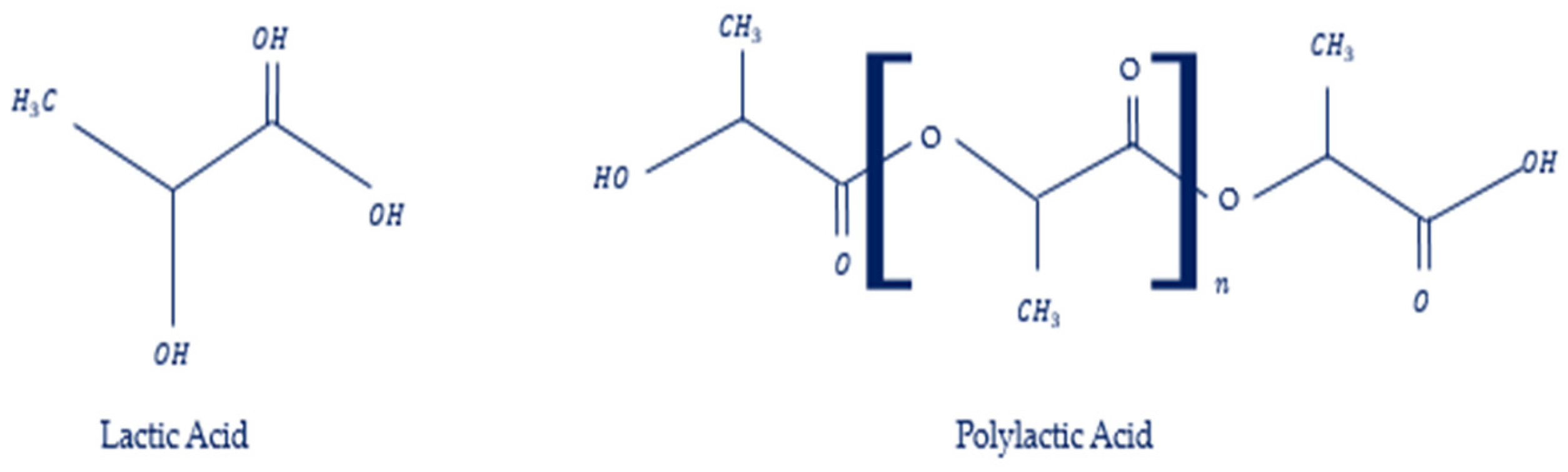
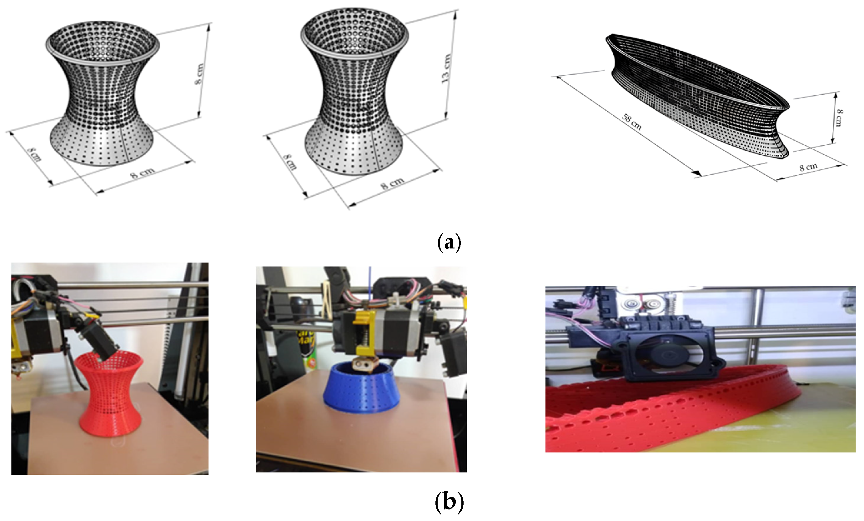
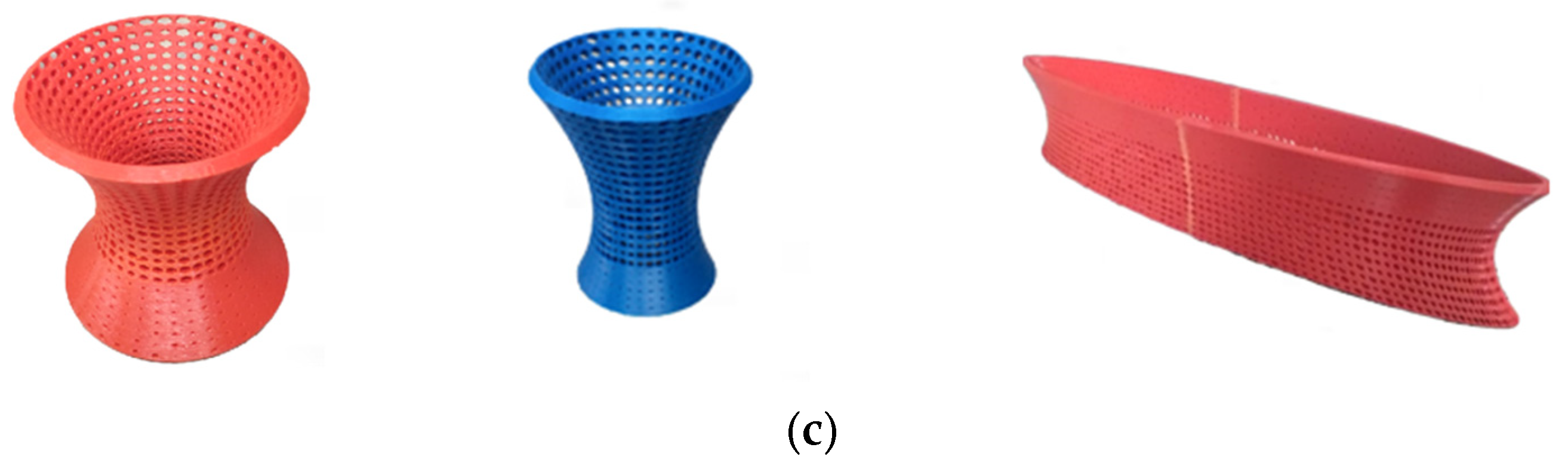
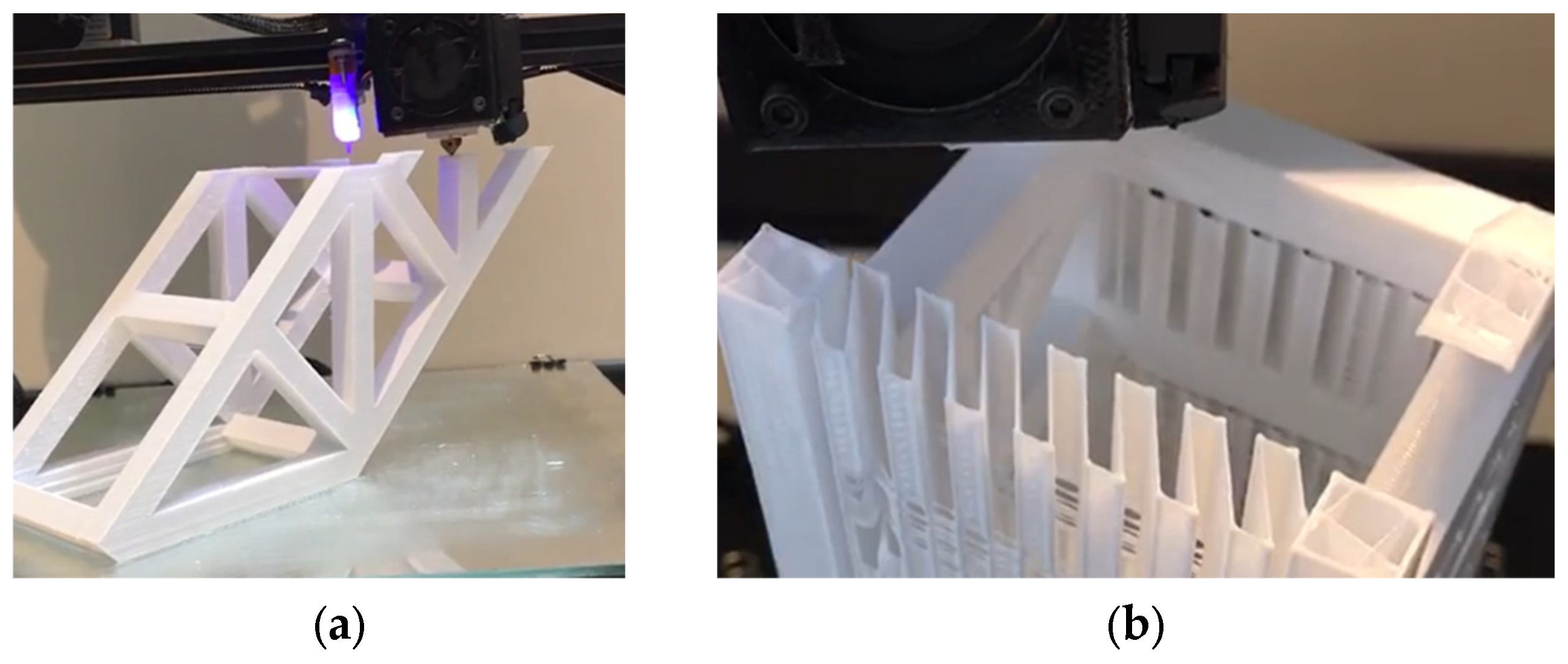
2.1. Three-Dimensional Printing Materials and Fabrication
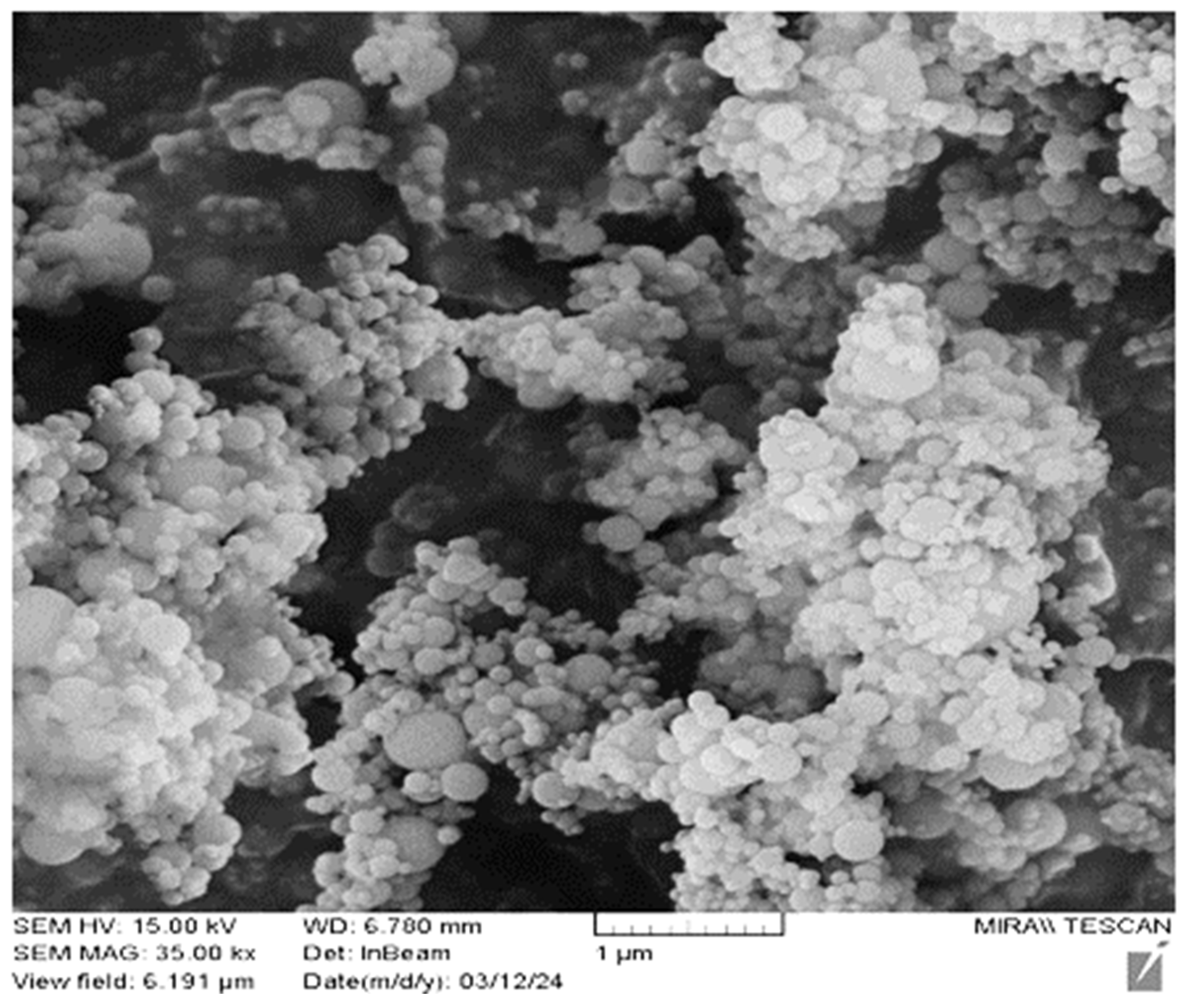
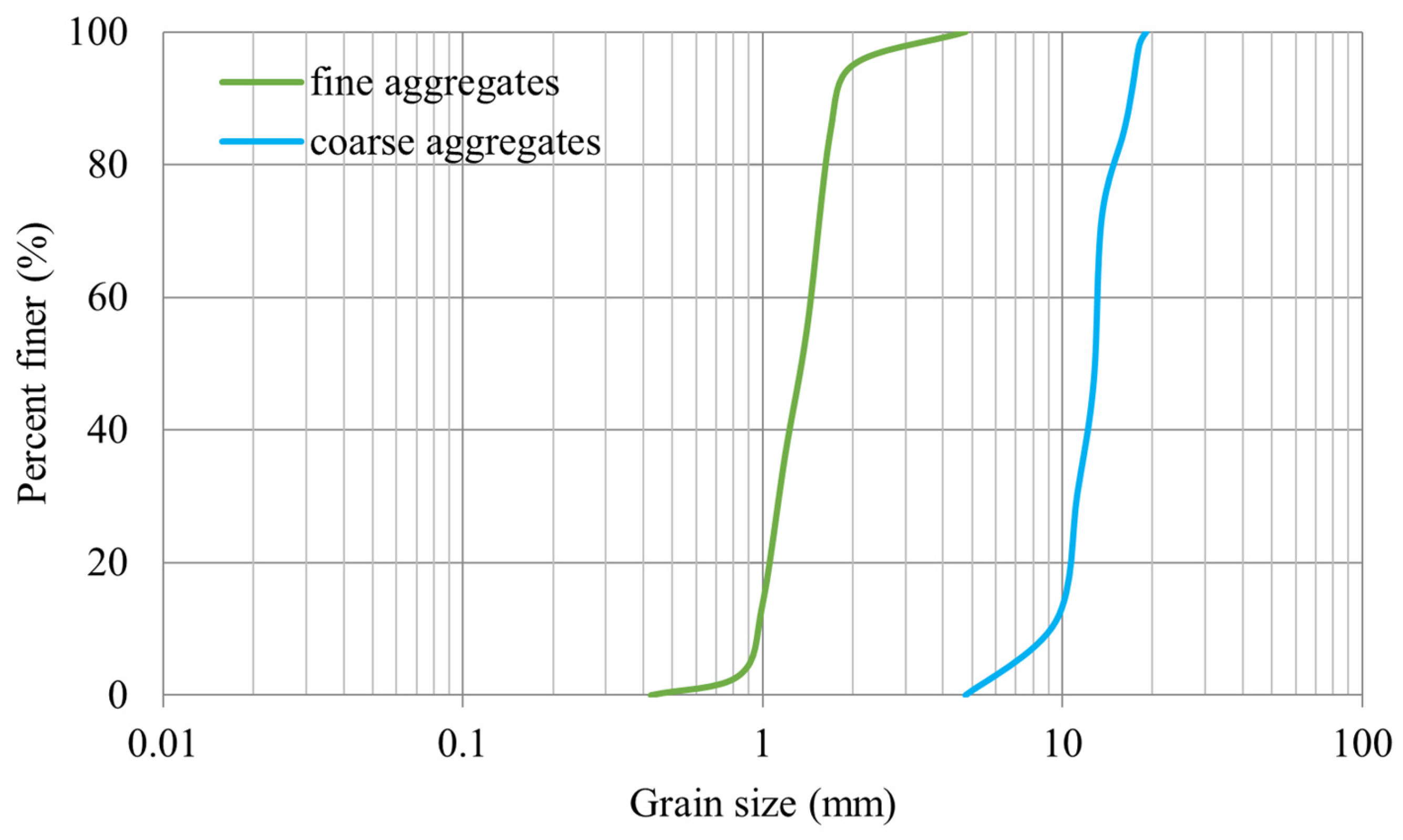
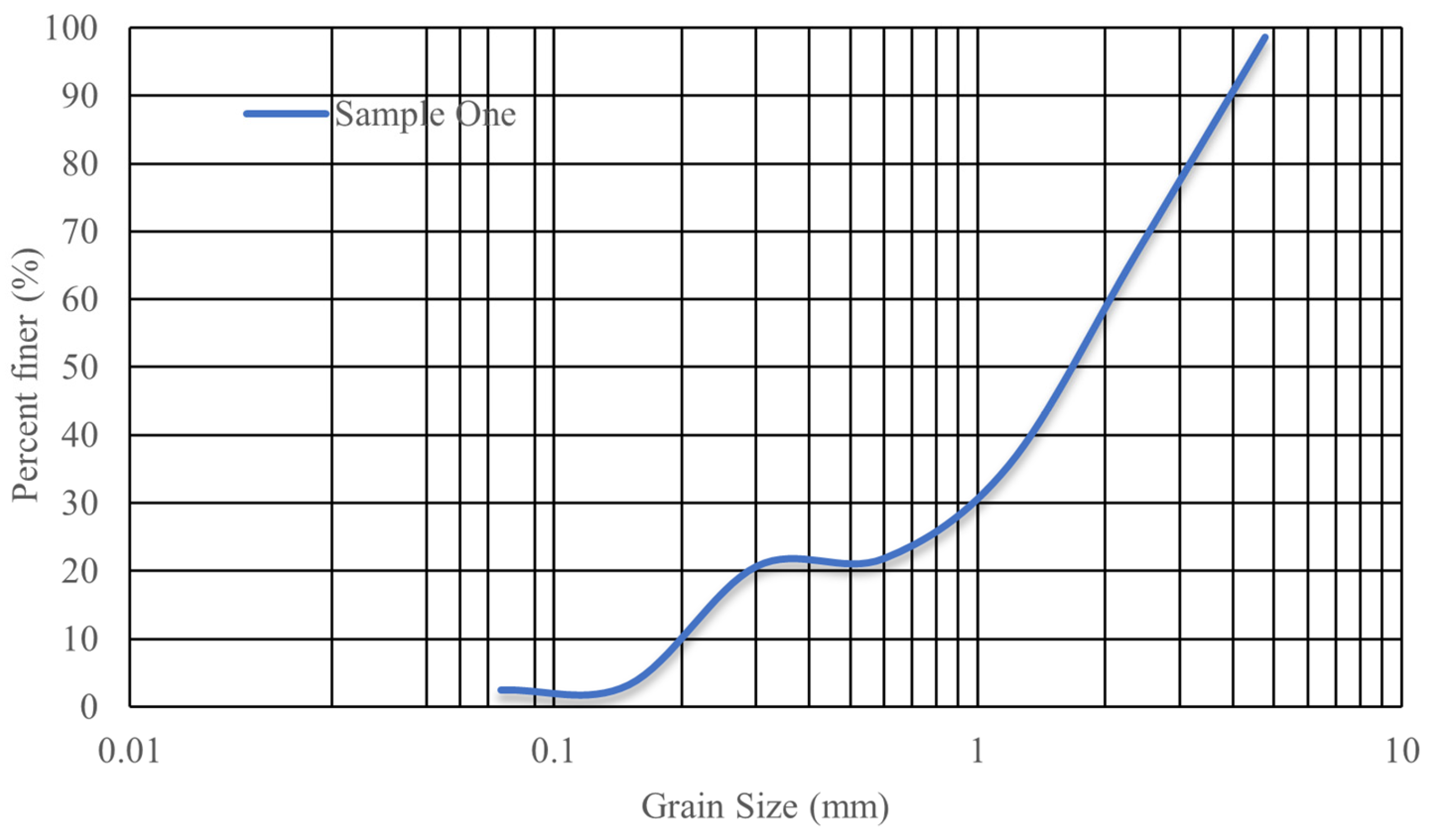
2.2. Concrete Materials
2.3. Experimental Method
2.3.1. HPC Reinforced with Trusses
2.3.2. UHPC Reinforced with Hyperboloid
3. Results
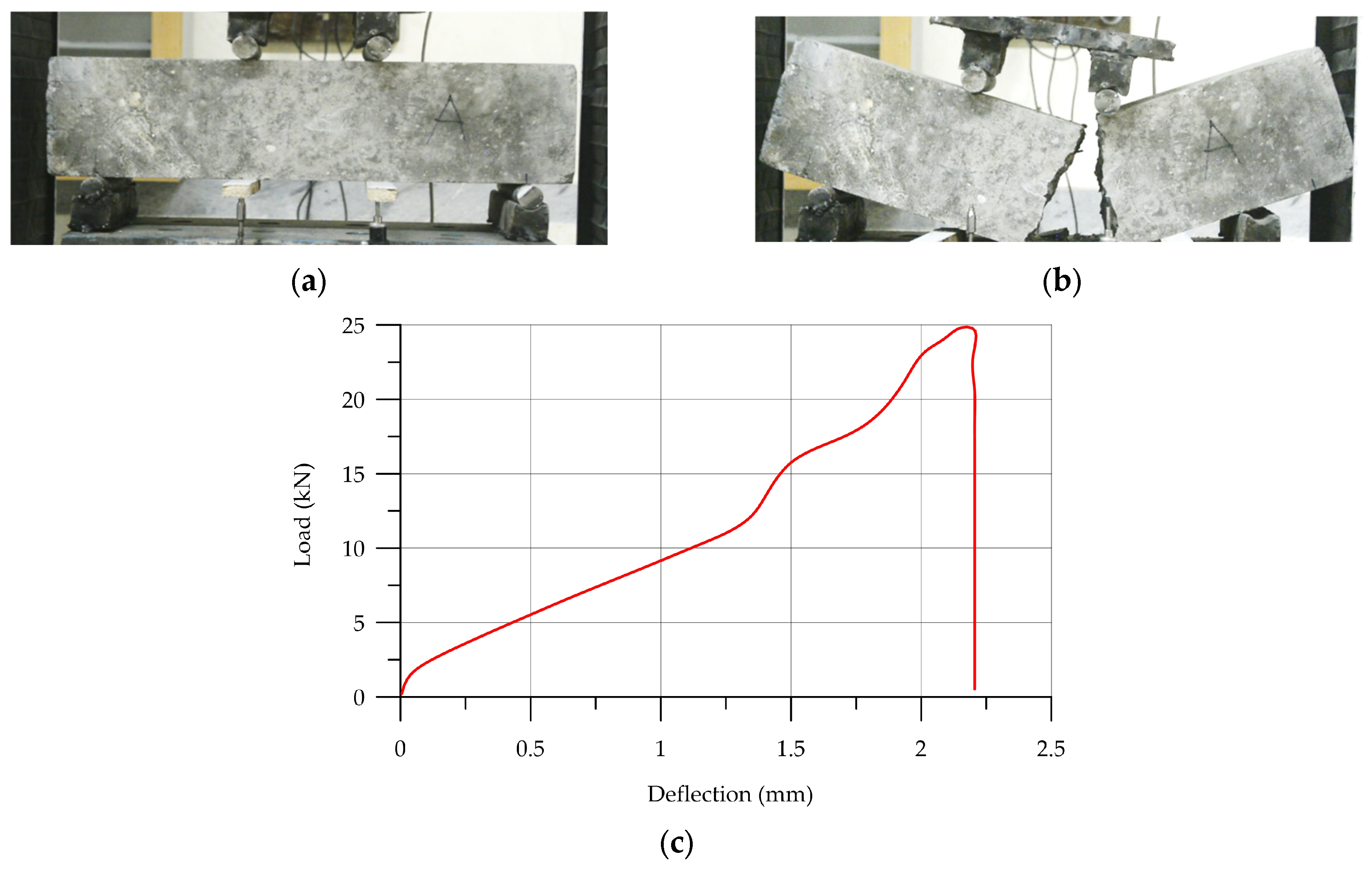
3.1. HPC Reinforced with Trusses
3.2. UHPC Reinforced with Hyperboloid Shell
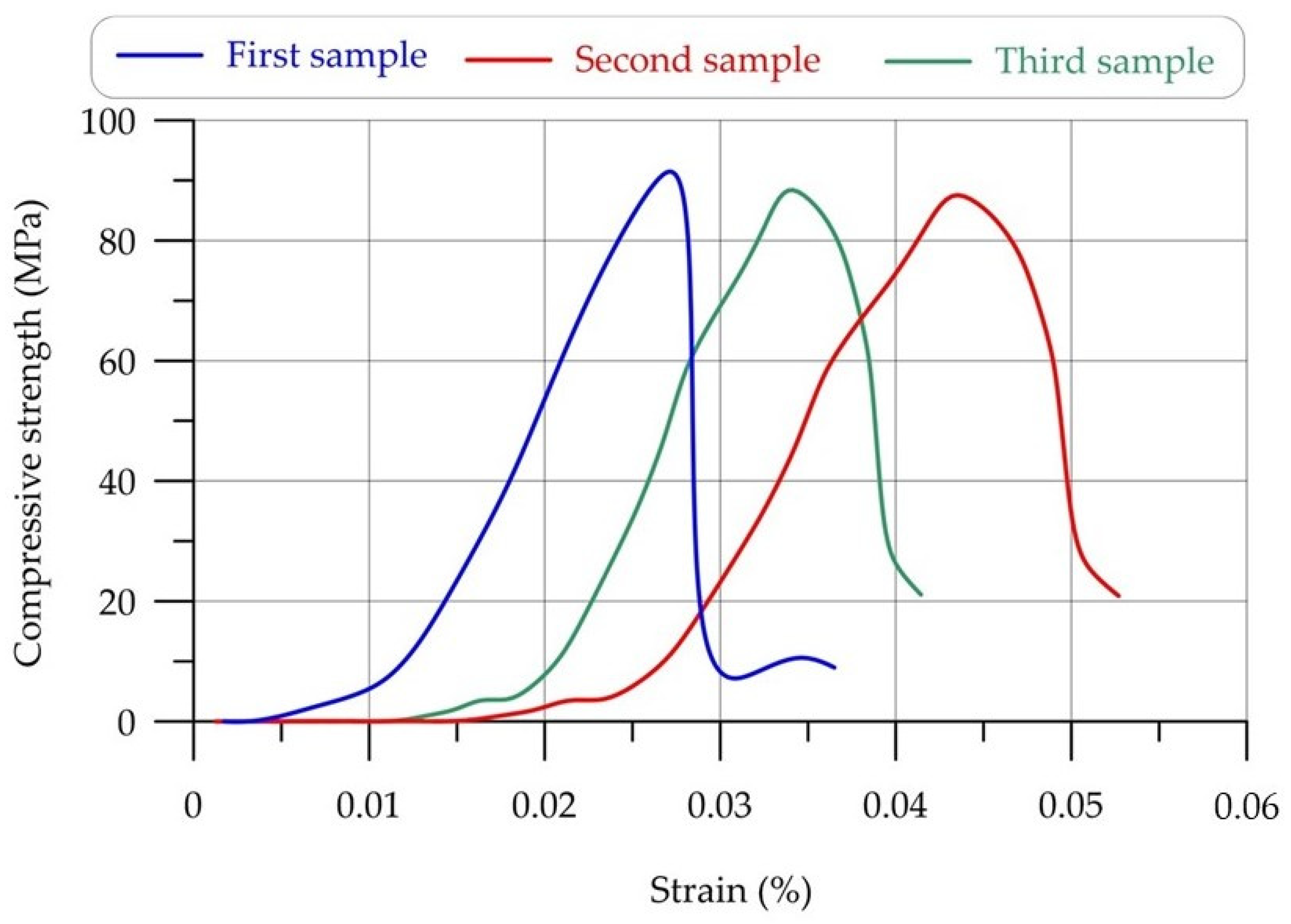
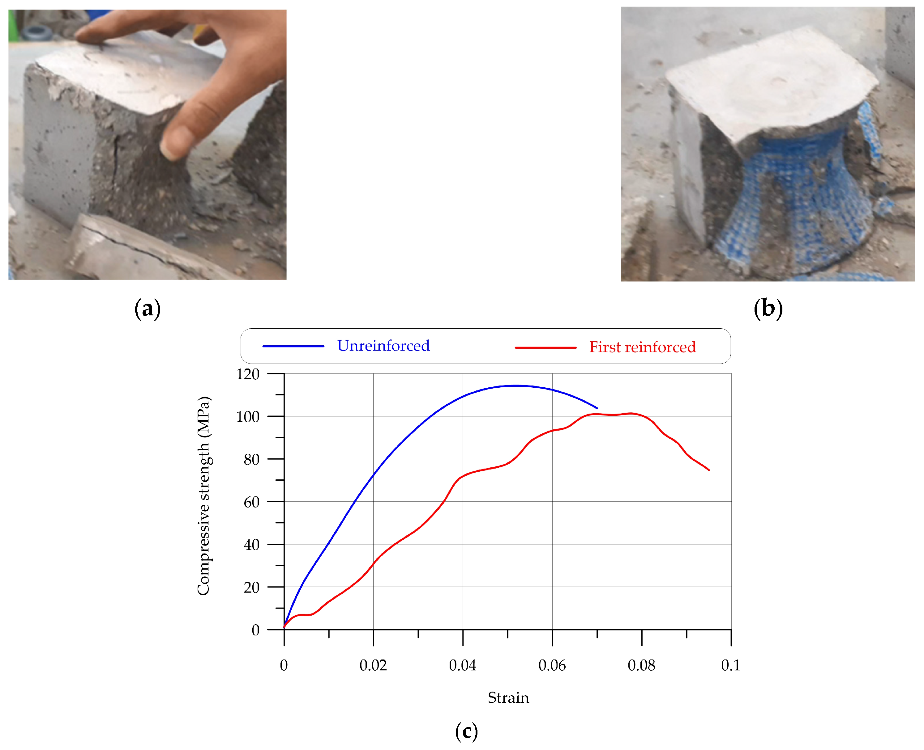
3.2.1. Compressive Strength Results
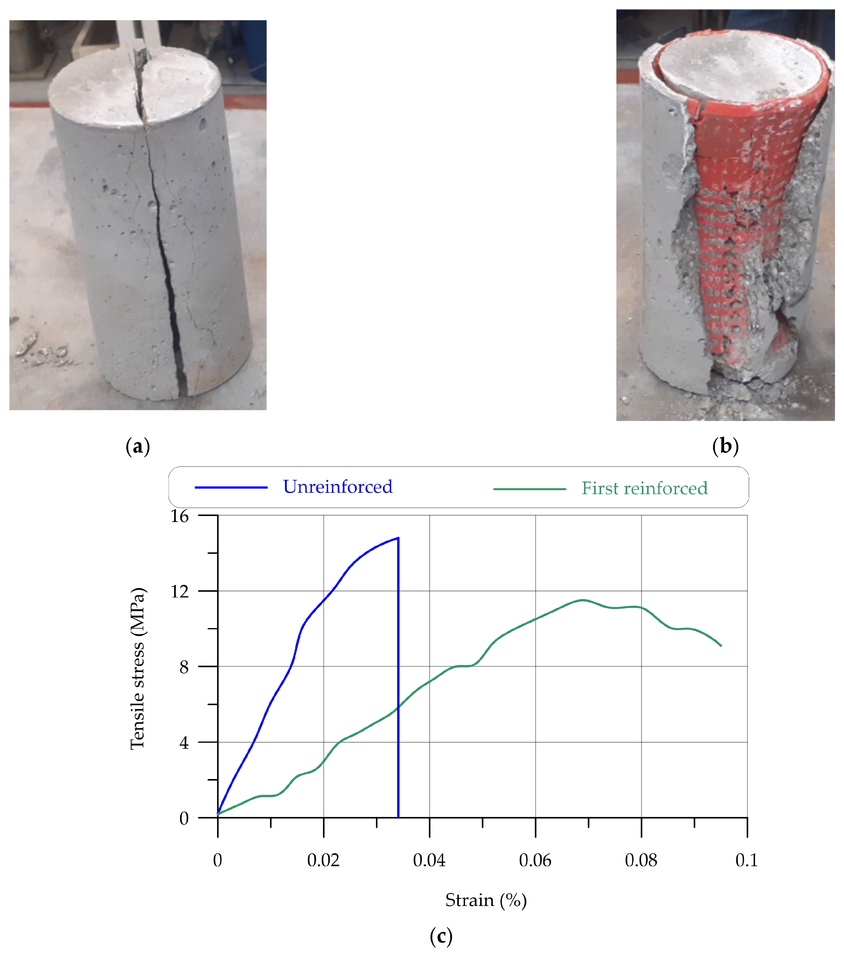
3.2.2. Tensile Strength Results
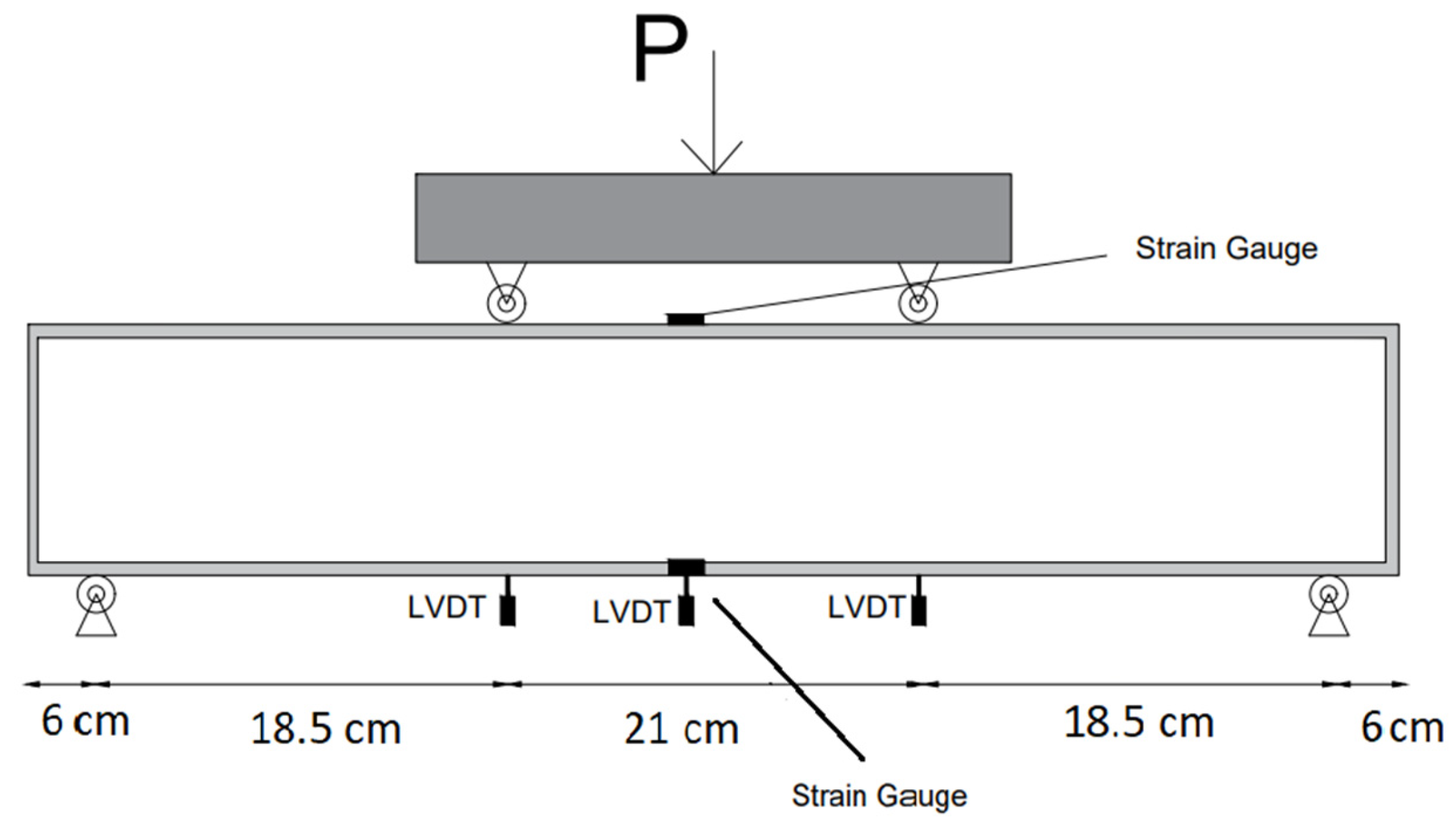
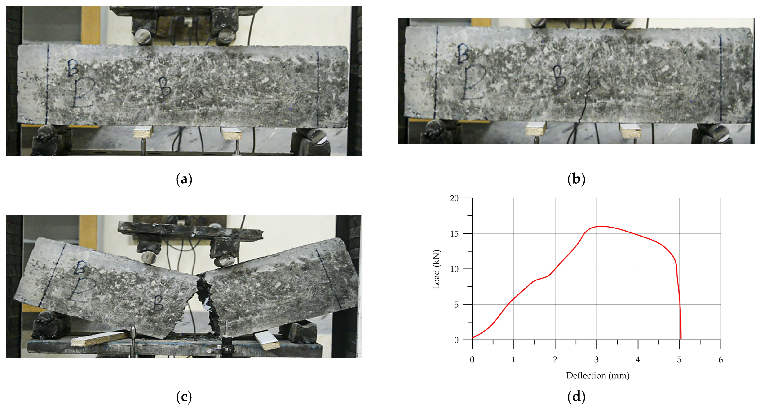
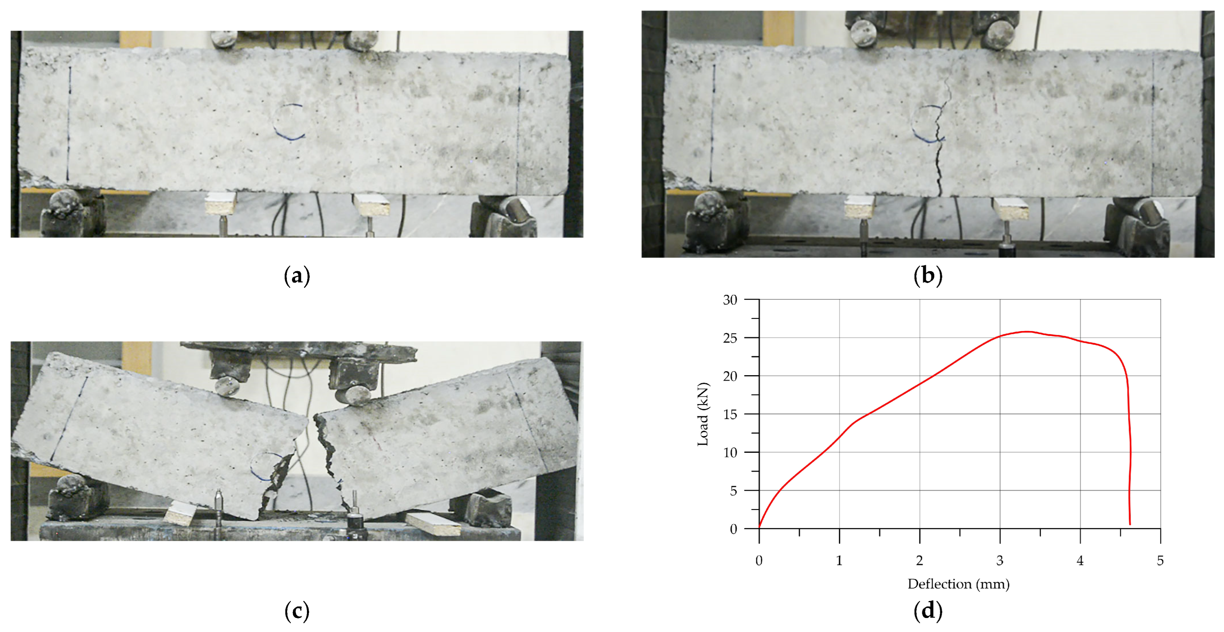
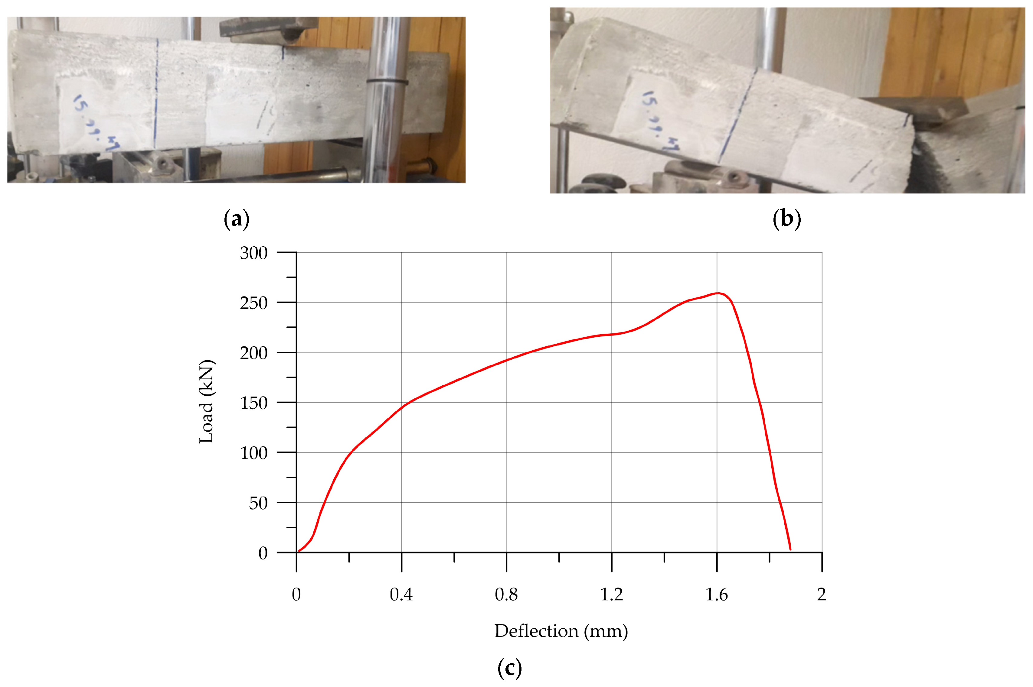
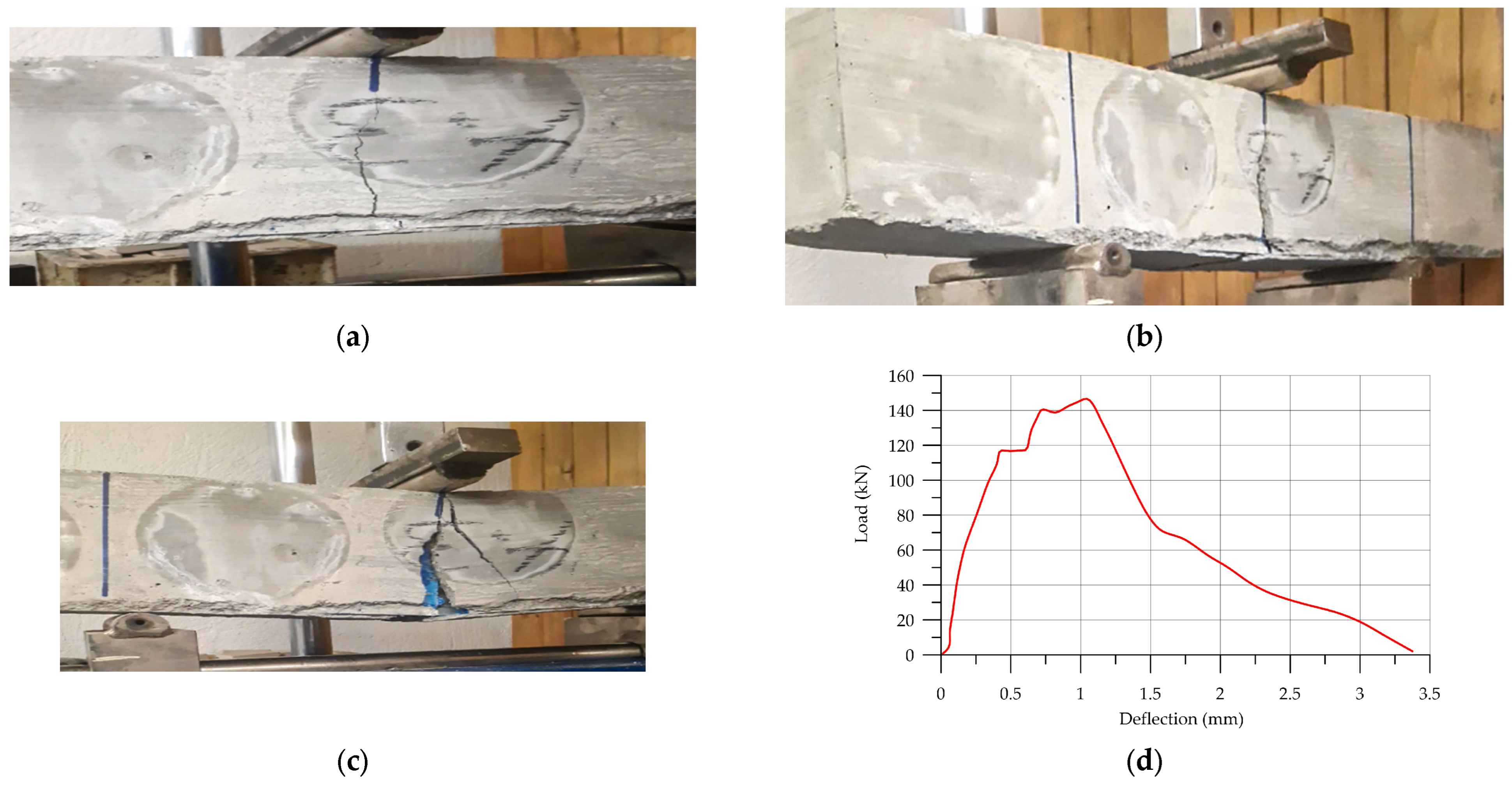
3.2.3. Three-Point Bending Test Results
4. Discussion
4.1. Differences between Two Types of Reinforcements
4.2. Differences between Current Study and Other Studies
5. Conclusions
- I.
- Hyperboloid shells and honeycomb structures can improve the energy absorption of reinforced concrete, although hyperboloid shell structures cannot improve the flexural strength of UHPC.
- II.
- Warren and Howe types of trusses can increase the flexural strength of HPC as 3D-printed reinforcements. Adding these two types of 3D-printed reinforcements can improve the flexural strength by over 12% and 4.4%, respectively.
- III.
- Research and studies show that the inclination angle of trusses is an important factor in increasing the mechanical properties and flexural strength. According to the results, the maximum mechanical properties of trusses are related to the inclination angle of 3D printing: 50° and 60°.
- IV.
- The results of this study show that the main factor in improving the ductility and mechanical properties of concrete is related to the geometry of 3D-printed shapes.
- V.
- This study suggests that further research into different types of hyperboloid shell structures to reinforce cementitious materials should be undertaken to find the positive or negative effect of hyperboloid geometry.
Author Contributions
Funding
Institutional Review Board Statement
Informed Consent Statement
Data Availability Statement
Acknowledgments
Conflicts of Interest
References
- Xu, Y.; Savija, B.; Schlangen, E. Compression Behaviors of Cementitious Cellular Composites with Negative Poisson’s Ratio. In Proceedings of the 10th International Conference on Fracture Mechanics of Concrete and Concrete, Bayonne, France, 23–26 June 2019. [Google Scholar]
- Xu, Y.; Zhang, H.; Gan, Y.; Šavija, B. Cementitious Composites Reinforced with 3D Printed Functionally Gradedpolymeric Lattice Structures: Experiments and Modelling. Addit. Manuf. 2021, 39, 101887. [Google Scholar] [CrossRef]
- He, Y.; Zhang, Y.; Zhang, C.; Zhou, H. Energy-Saving Potential of 3D Printed Concrete Building with Integrated Living Wall. Energy Build. 2020, 222, 110110. [Google Scholar] [CrossRef]
- Zou, S.; Cao, S.; Yilmaz, E. Enhancing Flexural Property and Mesoscopic Mechanism of Cementitious Tailings Backfill Fabricated with 3D-Printed Polymers. Constr. Build. Mater. 2024, 414, 135009. [Google Scholar] [CrossRef]
- Zhang, H.; Cao, S.; Yilmaz, E. Influence of 3D-Printed Polymer Structures on Dynamic Splitting and Crack Propagation Behavior of Cementitious Tailings Backfill. Constr. Build. Mater. 2022, 343, 128137. [Google Scholar] [CrossRef]
- Hack, N.; Bahar, M.; Hühne, C.; Lopez, W.; Gantner, S.; Khader, N.; Rothe, T. Development of A Robot-Based Multi-Directional Dynamic Fiber Winding Process for Additive Manufacturing Using Shotcrete 3D Printing. Fibers 2021, 9, 39. [Google Scholar] [CrossRef]
- Rezaieyan, E.; Taban, E.; Berardi, U.; Mortazavi, S.B.; Faridan, M.; Mahmoudi, E. Acoustic Properties of Natural Fiber Reinforced Composite Micro-Perforated Panel (NFRC-MPP) Made from Cork Fiber and Polylactic Acid (PLA) Using 3D Printing. J. Build. Eng. 2024, 84, 108491. [Google Scholar] [CrossRef]
- Farina, I.; Fabbrocino, F.; Carpentieri, G.; Modano, M.; Amendola, A.; Goodall, R.; Feo, L.; Fraternali, F. On the Reinforcement of Cement Mortars through 3D Printed Polymeric and Metallic Fibers. Compos. Part B 2016, 90, 76–85. [Google Scholar] [CrossRef]
- Tzortzinis, G.; Gross, A.; Gerasimidis, S. Auxetic Boosting of Confinement in Mortar by 3D Reentrant Truss Lattices for next Generation Steel Reinforced Concrete Members. Extrem. Mech. Lett. 2022, 52, 101681. [Google Scholar] [CrossRef]
- Gödek, E.; Evik, S.; Özdilli, O. Pattern and Filament Optimization for 3D-Printed Reinforcements to Enhance the Flexural Behavior of Cement-Based Composites. J. Sustain. Constr. Mater. Technol. 2023, 8, 47–56. [Google Scholar] [CrossRef]
- Katzer, J.; Szatkiewicz, T. Effect of 3D Printed Spatial Reinforcement onFlexural Characteristics of Conventional Mortar. Materials 2020, 13, 3133. [Google Scholar] [CrossRef]
- Xu, Y.; Zhang, H.; Schlangen, E.; Lukovic, M.; Savija, B. Cementitious Cellular Composites with Auxetic Behavior. Cem. Concr. Compos. 2020, 111, 103624. [Google Scholar] [CrossRef]
- Aghdasi, P.; Williams, I.D.; Salazar, B.; Panditi, N.; Taylor, H.K.; Ostertag, C.P. An Octet-Truss Engineered Concrete (OTEC) for Lightweight Structures. Compos. Struct. 2018, 207, 373–384. [Google Scholar] [CrossRef]
- Smith, C.W.; Grima, J.N.; Evans, K.E. A Novel Mechanism for Generating Auxetic Behaviour in Reticulated Foams: Missing Rib Foam Model. Acta Mater. 2000, 48, 4349–4356. [Google Scholar] [CrossRef]
- Su, W.; Wu, X.; Shi, J. A Novel 3D Printable Multimaterial Auxetic Metamaterial with Reinforced Structure: Improved Stiffness and Retained Auxetic Behavior. Mech. Adv. Mater. Struct. 2022, 29, 408–418. [Google Scholar] [CrossRef]
- Novak, K.; Hokamoto, K.; Vesenjak, M.; Ren, Z. Mechanical Behaviour of Auxetic Cellular Structures Built from Inverted Tetrapods at High Strain Rates. Int. J. Impact Eng. 2018, 122, 83–90. [Google Scholar] [CrossRef]
- Lakes, R. Foam Structures with a Negative Poisson’s Ratio. Science 1987, 235, 1038–1040. [Google Scholar] [CrossRef] [PubMed]
- Greaves, G.N.; Greer, A.L.; Lakes, R.S.; Lakes, R.S.; Rouxel, T. Poisson’s Ratio and Modern Materials. Nat. Mater. 2011, 10, 823–837. [Google Scholar] [CrossRef] [PubMed]
- Oladipo, B.; Matos, H.; Krishnan, N.M.A.; Das, S. Integrating Experiments, Finite Element Analysis, and Interpretable Machine Learning to Evaluate the Auxetic Response of 3D Printed Re-Entrant Metamaterials. J. Mater. Res. Technol. 2023, 25, 1612–1625. [Google Scholar] [CrossRef]
- Zhou, J.; Liu, H.; Dear, J.P.; Falzon, B.G.; Kazancı, Z. Comparison of Different Quasi-Static Loading Conditions of Additively Manufactured Composite Hexagonal and Auxetic Cellular Structures. Int. J. Mech. Sci. 2023, 244, 108054. [Google Scholar] [CrossRef]
- Fan, G.Z.; Ren, X.; Wang, S.L.; Luo, C.; Xie, Y.M. A Novel Cement-Based Auxetic Foam Composite: Experimental Study. Case Stud. Constr. Mater. 2022, 17, e01159. [Google Scholar] [CrossRef]
- Askarinejad, S.; Ashouri Choshali, H.; Flavin, C.; Rahbar, R. Effects of Tablet Waviness on the Mechanical Response of Architected Multilayered Materials: Modeling and Experiment. Compos. Struct. 2018, 195, 118–125. [Google Scholar] [CrossRef]
- Xu, Y.; Meng, Z.; Bol, R.J.M.; Savija, B. Spring-like Behavior of Cementitious Composite Enabled by Auxetic Hyperelastic Frame. Int. J. Mech. Sci. 2024, 275, 109364. [Google Scholar] [CrossRef]
- Xu, Y.; Savija, B. Auxetic Cementitious Composites (ACCs) with Excellent Compressive Ductility: Experiments and Modeling. Mater. Des. 2024, 237, 112572. [Google Scholar] [CrossRef]
- Hematibahar, M.; Hasanzadeh, A.; Ivanovich Vatin, N.; Kharun, M.; Shooshpasha, I. Influence of 3D-Printed Reinforcement on the Mechanical and Fracture Characteristics of Ultra High Performance Concrete. Results Eng. 2023, 19, 101365. [Google Scholar] [CrossRef]
- Chiadighikaobi, P.C.; Hasanzadeh, A.; Hematibahar, M.; Kharun, M.; Mousavi, M.S.; Stashevskaya, N.A.; Adedapo Adegoke, M. Evaluation of the Mechanical Behavior of High-Performance Concrete (HPC) Reinforced with 3D-Printed Trusses. Results Eng. 2024, 22, 102058. [Google Scholar] [CrossRef]
- Khan, A.; Ahmed, N.; Elaissari, A. Optimize PLA/EVA Polymers Blend Compositional Coating for next Generation Biodegradable Drug-Eluting Stents. Polymers 2022, 14, 3547. [Google Scholar] [CrossRef] [PubMed]
- Liu, S.; Li, Y.; Li, N. A Novel Free-Hanging 3D Printing Method for Continuous Carbon Fiber Reinforced Thermoplastic Lattice Truss Core Structures. Mater. Des. 2018, 137, 235–244. [Google Scholar] [CrossRef]
- Castillo Martinez, F.A.; Balciunas, E.M.; Salgado, J.M.; Domínguez González, J.M.; Converti, A.; de Souza Oliveira, R.P. Lactic Acid Properties, Applications and Production: A Review. Trends Food Sci. Technol. 2013, 30, 70–83. [Google Scholar] [CrossRef]
- Juturu, V.; Wu, J.C. Microbial Production of Lactic Acid: The Latest Development. Crit. Rev. Biotechnol. 2016, 36, 967–977. [Google Scholar] [CrossRef] [PubMed]
- Ahmad, A.; Othman, I.; Rambabu, K.; Bharath, G.; Taher, H.; Hasan, S.W.; Banat, F. Banat, Polymerization of Lactic Acid Produced from Food Waste by Metal Oxide-Assisted Dark Fermentation. Environ. Technol. Innov. 2021, 24, 101862. [Google Scholar] [CrossRef]
- Wu, R.D.; Shen, Y.; Liu, J.H.; Cheng, L.N.; Zhang, G.T.; Zhang, Y.Y. Effect of Iron Tailings and Slag Powders on Workability and Mechanical Properties of Concrete. Front. Mater. 2021, 8, 723119. [Google Scholar]
- Hu, Z.; Gu, X.; Liu, J.; Ge, X.; Wang, S.; Yin, S. Mechanical Properties and Hydration Mechanism of Iron Tailings–Cement-Based Supplementary Cementitious Materials. Buildings 2024, 14, 1044. [Google Scholar] [CrossRef]
- Bhagia, S.; Bornani, K.; Agrawal, R.; Satlewal, A.; Durkovič, J.; Lagana, R.; Bhagia, M.; Geun Yoo, C.; Zhao, X.; Kunc, V.; et al. Critical Review of FDM 3D Printing of PLA Biocomposites Filled with Biomass Resources, Characterization, Biodegradability, Upcycling and Opportunities for Biorefineries. Appl. Mater. Today 2021, 24, 101078. [Google Scholar] [CrossRef]
- Ishak, I.B.; Fleming, D.; Larochelle, P. Multiplane Fused Deposition Modeling: A Study of Tensile Strength. Mech. Based Des. Struct. Mach. 2019, 47, 583–598. [Google Scholar] [CrossRef]
- Fernandez-Vicente, M.; Calle, W.; Ferrandiz, S.; Conejero, A. Effect of Infill Parameters on Tensile Mechanical Behavior in Desktop 3D Printing, 3D Print. Addit. Manuf. 2016, 3, 183–192. [Google Scholar] [CrossRef]
- Bektas, S. Design of Hyperboloid Structures. MOJ Civ. Eng. 2017, 3, 414–420. [Google Scholar] [CrossRef]
- Guo, Y.L.; Zhu, B.L.; Zhou, P.; Zhang, Y.H.; Pi, Y.L. Experimental and Numerical Investigation into the Load Resistance and Hysteretic Response of Rhombic Grid Hyperboloid-Latticed Shells. Eng. Struct. 2017, 153, 700–716. [Google Scholar] [CrossRef]
- Guo, Y.L.; Zhang, Y.H.; Zhu, B.L.; Zhou, P.; Pi, Y.L. Experimental and Numerical Studies of Instability Mechanism and Load Resistance of Rhombic Grid Hyperboloid-Latticed Shells under Vertical Load. Eng. Struct. 2018, 166, 167–186. [Google Scholar] [CrossRef]
- Deng, Z.H.; Guo, R.; Zhou, H.; Tang, S.Y. Simulation of Hypervelocity Impact Characteristics of Gradient Corrugated-Core Sandwich Plates. Spacecr. Environ. Eng. 2018, 35, 7–13. [Google Scholar]
- Qi, C.; Yang, L.J.; Yang, S. Simulation and Optimization for Blast-Resistant Performances of a Graded Aluminum Foam Sandwich Structure. J. Vib. Shock. 2013, 32, 70–75. [Google Scholar]
- Li, W.C.; Xu, L.Y.; Zhang, X. Investigating the Effect of Honeycomb Structure Composite on Microwave Absorption Properties–ScienceDirect. Compos. Commun. 2020, 19, 182–188. [Google Scholar] [CrossRef]
- Stel’makh, S.A.; Shcherban’, E.M.; Beskopylny, A.N.; Mailyan, L.R.; Veremeenko, A.; Shilov, A.V.; Ananova, O.; Karalar, M.; Aksoylu, C.; Onuralp Özkılıç, Y. Modeling and Calculation of Improved Centrifuged Reinforced Concrete Columns with Variotropic Structure. Buildings 2023, 13, 2005. [Google Scholar] [CrossRef]
- Beskopylny, A.N.; Meskhi, B.; Stel’makh, S.A.; Shcherban’, E.M.; Mailyan, L.R.; Veremeenko, A.; Akopyan, V.; Shilov, A.V.; Chernil’nik, A.; Beskopylny, N. Numerical Simulation of the Bearing Capacity of Variotropic Short Concrete Beams Reinforced with Polymer Composite Reinforcing Bars. Polymers 2022, 14, 3051. [Google Scholar] [CrossRef] [PubMed]
- Meskhi, B.; Beskopylny, A.N.; Stel’makh, S.A.; Shcherban’, E.M.; Mailyan, L.R.; Beskopylny, N.; Dotsenko, N. Theoretical and Experimental Substantiation of the Efficiency of Combined-Reinforced Glass Fiber Polymer Composite Concrete Elements in Bending. Polymers 2022, 14, 2324. [Google Scholar] [CrossRef] [PubMed]
- Stel’makh, S.A.; Shcherban’, E.M.; Beskopylny, A.; Mailyan, L.R.; Meskhi, B.; Dotsenko, N. Enchainment of the Coefficient of Structural Quality of Elements in Compression and Bending by Combined Reinforcement of Concrete with Polymer Composite Bars and Dispersed Fiber. Polymers 2021, 13, 4347. [Google Scholar] [CrossRef] [PubMed]
- Beskopylny, A.N.; Stel’makh, S.A.; Shcherban’, E.M.; Mailyan, L.R.; Meskhi, B.; Efremenko, I.; Varavka, V.; Beskopylny, N.; Dotsenko, N. Modeling and Experimental Verification of the Performance of Polymer Composite Reinforcing Bars of Different Types in Concrete of Different Density. Polymers 2022, 14, 1756. [Google Scholar] [CrossRef] [PubMed]
- Shcherban’, E.M.; Stel’makh, S.A.; Mailyan, L.R.; Beskopylny, A.N.; Smolyanichenko, A.S.; Chernil’nik, A.; Elshaeva, D.; Beskopylny, N. Influence of Polymer Fibers on the Structure and Properties of Modified Variatropic Vibrocentrifuged Concrete. Polymers 2024, 16, 642. [Google Scholar] [CrossRef] [PubMed]
- Stel’makh, S.A.; Shcherban’, E.M.; Beskopylny, A.; Mailyan, L.R.; Meskhi, B.; Varavka, V. Quantitative and Qualitative Aspects of Composite Action of Concrete and Dispersion-Reinforcing Fiber. Polymers 2022, 14, 682. [Google Scholar] [CrossRef] [PubMed]
- Jiang, W.; Ma, H.; Wang, J.; Feng, M.; Qu, S. Mechanical Metamaterial with Negative Poisson’s Ratio Based on Circular Honeycomb Core. Chin. Sci. Bull. 2016, 61, 1421–1427. [Google Scholar] [CrossRef]
- Lin, K.; Gu, D.; Hu, K.; Yang, J.; Wang, H.; Yuan, L.; Shi, X.; Meng, L. Laser Powder Bed Fusion of Bio-Inspired Honeycomb Structures: Effect of Twist Angle on Compressive Behaviors. Thin-Walled Struct. 2021, 159, 107252. [Google Scholar] [CrossRef]
- Widjajakusuma, J.; Wijaya, H. Effect of Geometries on the Natural Frequencies of Pratt Truss Bridges. Procedia Eng. 2015, 125, 1149–1155. [Google Scholar] [CrossRef]
- Cywiliski, Z.; Jasina, J.; Niewitecki, S. Howe Truss Behavior Interpreted by Deflections. J. Perform. Constr. Facil. 1992, 6, 151–160. [Google Scholar] [CrossRef]
- Wittbrodt, B.; Pearce, J. The Effects of PLA Color on Material Properties of 3-D Printed Components. Addit. Manuf. 2015, 8, 110–116. [Google Scholar] [CrossRef]
- Neville, A.M. Properties of Concrete, 5th ed.; Pearson: London, UK, 2012. [Google Scholar]
- Ghavami, S.; Naseri, H.; Jahanbakhsh, H.; Moghadas Nejad, F. The Impacts of Nano-SiO2 and Silica Fume on Cement Kiln Dust Treated Soil as a Sustainable Cement Free Stabilizer. Constr. Build. Mater. 2021, 285, 122918. [Google Scholar] [CrossRef]
- Hasanzadeh, A.; Shooshpasha, I. Influences of Silica Fume Particles and Polyethylene Terephthalate Fibers on the Mechanical Characteristics of Cement-Treated Sandy Soil Using Ultrasonic Pulse Velocity. Bull. Eng. Geol. Env. 2022, 8, 14. [Google Scholar] [CrossRef]
- Hasanzadeh, A.; Ivanovich Vatin, N.; Hematibahar, M.; Kharun, M.; Shooshpasha, I. Prediction of the Mechanical Properties of Basalt Fiber Reinforced High-Performance Concrete Using Machine Learning Techniques. Materials 2022, 15, 7165. [Google Scholar] [CrossRef] [PubMed]
- Hematibahar, M.; Ivanovich Vatin, N.; Alaraza, H.A.; Khalilavi, H.; Kharun, M. The Prediction of Compressive Strength and Compressive Stress-Strain of Basalt Fiber Reinforced High-Performance Concrete Using Classical Programming and Logistic Map Algorithm. Materials 2022, 15, 6975. [Google Scholar] [CrossRef] [PubMed]
- GOST 10180; Betony. Metody Opredeleniya Prochnosti Po Kontrolnym Obraztsam [Concretes. Methods for Determination of Strength by Control Samples]. Standartinform: Moscow, Russia, 2018.
- ASTM C109; Standard Test Method for Compressive Strength of Hydraulic Cement Mortars (Using 2-in. or [50-Mm] Cube Specimens). ASTM International: West Conshohocken, PA, USA, 2017. [CrossRef]
- ASTM C496/C496M-17; Standard Test Method for Splitting Tensile Strength of Cylindrical Concrete Specimens. ASTM International: West Conshohocken, PA, USA, 2017.
- ASTM C293/C293M-16; Standard Test Method for Flexural Strength of Concrete (Using Simple Beam with Center-Point Loading). ASTM International: West Conshohocken, PA, USA, 2016.
- ASTM C1609/C1609M; Standard Test Method for Flexural Performance of Fiber Reinforced Concrete (Using Beam with Third-Point Loading). ASTM International: West Conshohocken, PA, USA, 2012; pp. 1–9.
- Wang, Z.; Luan, C.; Liao, G.; Yao, X.; Fu, J. Mechanical and Self-Monitoring Behaviors of 3D Printing Smart Continuous Carbon Fiber-Thermoplastic Lattice Truss Sandwich Structure. Compos. B Eng. 2019, 176, 107215. [Google Scholar] [CrossRef]
- Zhang, D.; Tian, X.; Zhou, Y.; Wang, Q.; Yan, W.; Akmal Zia, A.; Wu, L.; Li, D. Spatial 3D Printing of Continuous Fiber-Reinforced Composite Multilayer Truss Structures with Controllable Structural Performance. Polymers 2023, 15, 4333. [Google Scholar] [CrossRef]
- Tyurikov, E.V. On the Construction of Mathematical Models of the Membrane Theory of Convex Shells. Adv. Eng. Res. 2023, 23, 17–25. [Google Scholar] [CrossRef]
- Ismayilova, J.J. Analysis of Stress-Strain State of a Cylinder with Variable Elasticity Moduli Based on Three-Dimensional Equations of Elasticity Theory. Adv. Eng. Res. 2023, 23, 113–120. [Google Scholar] [CrossRef]
- Le, T.T.; Austin, S.A.; Lim, S.; Buswell, R.A.; Law, R.; Gibb, A.G.F.; Thorpe, T. Hardened Properties of High-Performance Printing Concrete. Cem. Concr. Res. 2012, 42, 558–566. [Google Scholar] [CrossRef]
- Mechtcherine, V.; Grafe, J.; Nerella, V.N.; Spaniol, E.; Hertel, M.; Füssel, U. 3D-Printed Steel Reinforcement for Digital Concrete Construction–Manufacture, Mechanical Properties and Bond Behaviour. Construct. Build. Mater. 2018, 179, 125–137. [Google Scholar] [CrossRef]
- Salazar, B.; Aghdasi, P.; Williams, I.D.; Ostertag, C.P.; Taylor, H.K. Polymer Lattice-Reinforcement for Enhancing Ductility of Concrete. Mater. Des. 2020, 196, 109184. [Google Scholar] [CrossRef]
- Xu, Y.; Šavija, B. Development of Strain Hardening Cementitious Composite (SHCC) Reinforced with 3D Printed Polymeric Reinforcement: Mechanical Properties. Compos. Part B Eng. 2019, 174, 107011. [Google Scholar] [CrossRef]
- Hao, W.; Liu, J.; Kanwal, H. Compressive Properties of Cementitious Composites Reinforced by 3D Printed PA 6 Lattice. Polym. Test. 2023, 117, 107811. [Google Scholar] [CrossRef]
- Chen, M.; Chen, Z.; Xuan, Y.; Zhang, T.; Zhang, M. Static and Dynamic Compressive Behaviour of 3D Printed Auxetic Lattice Reinforced Ultra-High Performance Concrete. Cem. Concr. Compos. 2023, 139, 105046. [Google Scholar] [CrossRef]
- Rosewitz, J.A.; Ashouri Choshali, H.; Rahbar, R. Bioinspired Design of Architected Cement-Polymer Composites. Bioinspired Des. Archit. Cem.-Polym. Compos. 2019, 96, 252–265. [Google Scholar] [CrossRef]
- Momoh, E.O.; Jayasinghe, A.; Hajsadeghi, M.; Vinai, R.; Evans, K.E.; Kripakaran, P.; Orr, J. A State-of-the-Art Review on the Application of Auxetic Materials in Cementitious Composites. Thin-Walled Struct. 2024, 196, 111447. [Google Scholar] [CrossRef]


| Details | 3D-Printed Trusses | 3D-Printed Hyperboloid |
|---|---|---|
| Layer thickness (mm) | 0.2 | 0.2 |
| Printing speed (mm/s) | 50 | 50 |
| Infill percentage (%) | 45 | 30 |
| Extruder temperature (°C) | 190 | 190 |
| Bed temperature (°C) | 60 | 60 |
| Material | Ultimate Tensile Strength (MPa) | Yield Strength (MPa) | Maximum Strain (%) |
|---|---|---|---|
| PLA | 57.16 ± 0.35 | 52.47 ± 0.35 | 2.35 ± 0.05 |
| Chemical Composition | Value (%) | |
|---|---|---|
| Silica Fume | Cement | |
| SiO2 | 90–92 | 19.52 |
| Al2O3 | 0.68 | 4.81 |
| Fe2O3 | 0.69 | 4.08 |
| CaO | 1.58 | 62.18 |
| SO3 | - | 2.81 |
| K2O | - | 0.6 |
| MgO | 1.01 | - |
| Na2O | 0.61 | - |
| K2O | 1.23 | - |
| C | 0.98 | - |
| S | 0.23 | - |
| L.O.I | - | 1.67 |
| Material | Cement (kg/m3) | Water (kg/m3) | Superplasticizer (kg/m3) | Sand (kg/m3) | Gravel (kg/m3) | Silica Fume (kg/m3) |
|---|---|---|---|---|---|---|
| HPC | 500 | 187.5 | 12.5 | 585 | 1005 | 128 |
| Material | Cement (kg/m3) | Water (kg/m3) | Superplasticizer (kg/m3) | Fine Aggregate (kg/m3) | Gravel (kg/m3) | Silica Fume (kg/m3) |
|---|---|---|---|---|---|---|
| UHPC | 420 | 105 | 12.6 | 945 | 635 | 65 |
| Sample | Maximum Load (kN) | First Crack Deflection (mm) | Maximum Deflection (mm) | Deflection Recorded by Left LVDT (mm) | Deflection Recorded by Right LVDT (mm) | Weight (kg) |
|---|---|---|---|---|---|---|
| P-HPC-1 | 15.9 | 3.04 | 5.03 | 2.68 | 4.03 | 45.3 |
| P-HPC-2 | 15.5 | 3.09 | 5.11 | 2.73 | 4.09 | 45.1 |
| P-HPC-3 | 16 | 2.93 | 4.92 | 2.61 | 3.96 | 45.3 |
| Sample | Maximum Load (kN) | First Crack Deflection (mm) | Maximum Deflection (mm) | Deflection Recorded by Left LVDT (mm) | Deflection Recorded by Right LVDT (mm) | Weight (kg) |
|---|---|---|---|---|---|---|
| H-HPC-1 | 25.5 | 3.19 | 4.61 | 0.78 | 1.25 | 45.5 |
| H-HPC-2 | 24.3 | 3.12 | 4.42 | 0.70 | 1.21 | 45.3 |
| H-HPC-3 | 26.2 | 3.28 | 4.78 | 0.78 | 1.30 | 45.4 |
| Sample | Maximum Load (kN) | First Crack Deflection (mm) | Maximum Deflection (mm) | Deflection Recorded by Left LVDT (mm) | Deflection Recorded by Right LVDT (mm) | Weight (kg) |
|---|---|---|---|---|---|---|
| W-HPC-1 | 27.9 | 2.64 | 4.45 | 3.52 | 2.85 | 44.6 |
| W-HPC-2 | 27.6 | 2.86 | 4.58 | 3.63 | 3.01 | 44.6 |
| W-HPC-3 | 28.1 | 2.41 | 4.23 | 3.44 | 2.63 | 44.5 |
| Sample | Maximum Load (kN) | First Crack Deflection (mm) | Maximum Deflection (mm) | Deflection Recorded by Left LVDT (mm) | Deflection Recorded by Right LVDT (mm) | Weight (kg) |
|---|---|---|---|---|---|---|
| WV-HPC-1 | 31.9 | 2.42 | 3.94 | 2.56 | 2.88 | 43.5 |
| WV-HPC-2 | 20.6 | 2.26 | 3.82 | 2.33 | 2.75 | 43.8 |
| WV-HPC-3 | 22.3 | 2.59 | 4.03 | 2.74 | 3.02 | 43.6 |
| Sample | Maximum Load (kN) | First Crack Deflection (mm) | Deflection Recorded by Left LVDT (mm) | Deflection Recorded by Right LVDT (mm) | Weight (kg) |
|---|---|---|---|---|---|
| HPC-1 | 24.4 | 2.21 | 0.25 | 0.21 | 46 |
| HPC-2 | 24.1 | 2.41 | 0.28 | 0.26 | 45.8 |
| HPC-3 | 24.6 | 2.10 | 0.22 | 0.18 | 46.1 |
| Samples | Unreinforced | Reinforced | ||||
|---|---|---|---|---|---|---|
| First Sample | Second Sample | Third Sample | First Sample | Second Sample | Third Sample | |
| Ultimate Strength (MPa) | 113 | 117 | 110 | 99 | 82 | 93 |
| Average Ultimate Strength (MPa) | 114 | 91 | ||||
| Samples | Unreinforced | Reinforced | ||||
|---|---|---|---|---|---|---|
| First Sample | Second Sample | Third Sample | First Sample | Second Sample | Third Sample | |
| Ultimate Strength (MPa) | 14.5 | 15.8 | 16.1 | 11.4 | 10.7 | 11.1 |
| Average Ultimate Strength (MPa) | 15.4 | 11.1 | ||||
| Samples | Unreinforced | Reinforced | ||||
|---|---|---|---|---|---|---|
| First Sample | Second Sample | Third Sample | First Sample | Second Sample | Third Sample | |
| Flexural Strength (kN) | 38.1 | 40.5 | 42.6 | 33.1 | 35.2 | 38.8 |
| Average Flexural Strength (kN) | 40.4 | 35.7 | ||||
| Sample | Maximum Load (kN) | First Crack Deformation (mm) | Maximum Deflection (mm) |
|---|---|---|---|
| HPC | 24.4 | - | 0.25 |
| P-HPC | 15.9 | 3.04 | 2.68 |
| H-HPC | 25.5 | 3.19 | 0.74 |
| W-HPC | 27.9 | 2.64 | 3.52 |
| WV-HPC | 21.9 | 2.42 | 2.56 |
| Unreinforced UHPC | 247.15 | - | 1.88 |
| Reinforced UHPC | 145.2 | 0.62 | 3.42 |
Disclaimer/Publisher’s Note: The statements, opinions and data contained in all publications are solely those of the individual author(s) and contributor(s) and not of MDPI and/or the editor(s). MDPI and/or the editor(s) disclaim responsibility for any injury to people or property resulting from any ideas, methods, instructions or products referred to in the content. |
© 2024 by the authors. Licensee MDPI, Basel, Switzerland. This article is an open access article distributed under the terms and conditions of the Creative Commons Attribution (CC BY) license (https://creativecommons.org/licenses/by/4.0/).
Share and Cite
Hematibahar, M.; Hasanzadeh, A.; Kharun, M.; Beskopylny, A.N.; Stel’makh, S.A.; Shcherban’, E.M. The Influence of Three-Dimensionally Printed Polymer Materials as Trusses and Shell Structures on the Mechanical Properties and Load-Bearing Capacity of Reinforced Concrete. Materials 2024, 17, 3413. https://doi.org/10.3390/ma17143413
Hematibahar M, Hasanzadeh A, Kharun M, Beskopylny AN, Stel’makh SA, Shcherban’ EM. The Influence of Three-Dimensionally Printed Polymer Materials as Trusses and Shell Structures on the Mechanical Properties and Load-Bearing Capacity of Reinforced Concrete. Materials. 2024; 17(14):3413. https://doi.org/10.3390/ma17143413
Chicago/Turabian StyleHematibahar, Mohammad, Ali Hasanzadeh, Makhmud Kharun, Alexey N. Beskopylny, Sergey A. Stel’makh, and Evgenii M. Shcherban’. 2024. "The Influence of Three-Dimensionally Printed Polymer Materials as Trusses and Shell Structures on the Mechanical Properties and Load-Bearing Capacity of Reinforced Concrete" Materials 17, no. 14: 3413. https://doi.org/10.3390/ma17143413
APA StyleHematibahar, M., Hasanzadeh, A., Kharun, M., Beskopylny, A. N., Stel’makh, S. A., & Shcherban’, E. M. (2024). The Influence of Three-Dimensionally Printed Polymer Materials as Trusses and Shell Structures on the Mechanical Properties and Load-Bearing Capacity of Reinforced Concrete. Materials, 17(14), 3413. https://doi.org/10.3390/ma17143413