
Bending Forming Characteristics of CoCrFeMnNi High-Entropy Alloy Sheets Induced by Nanosecond Pulse Laser Irradiation


Abstract
:1. Introduction
2. Materials and Methods
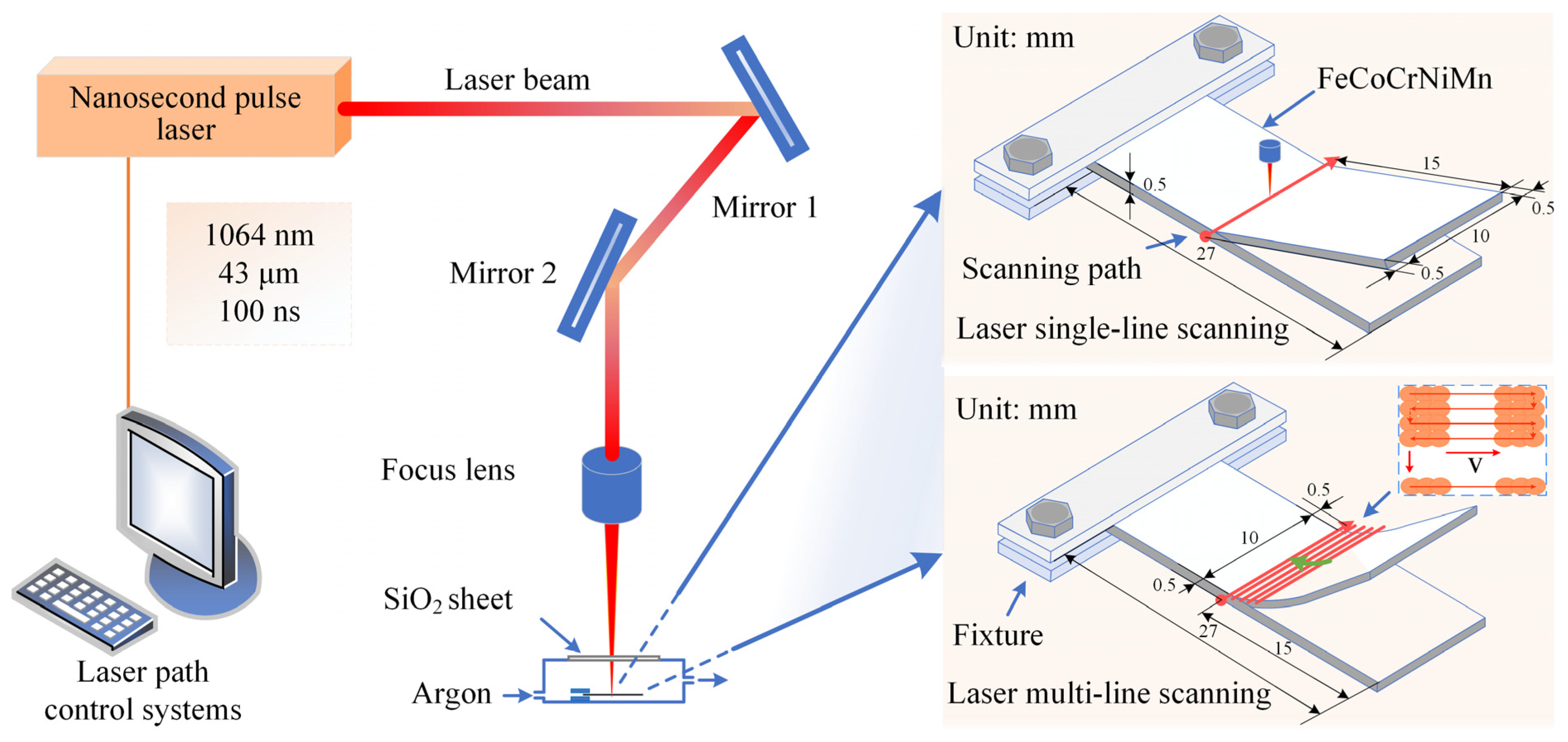
2.1. Materials and Experimental Procedures
2.2. Surface Characterization
3. Results and Discussion
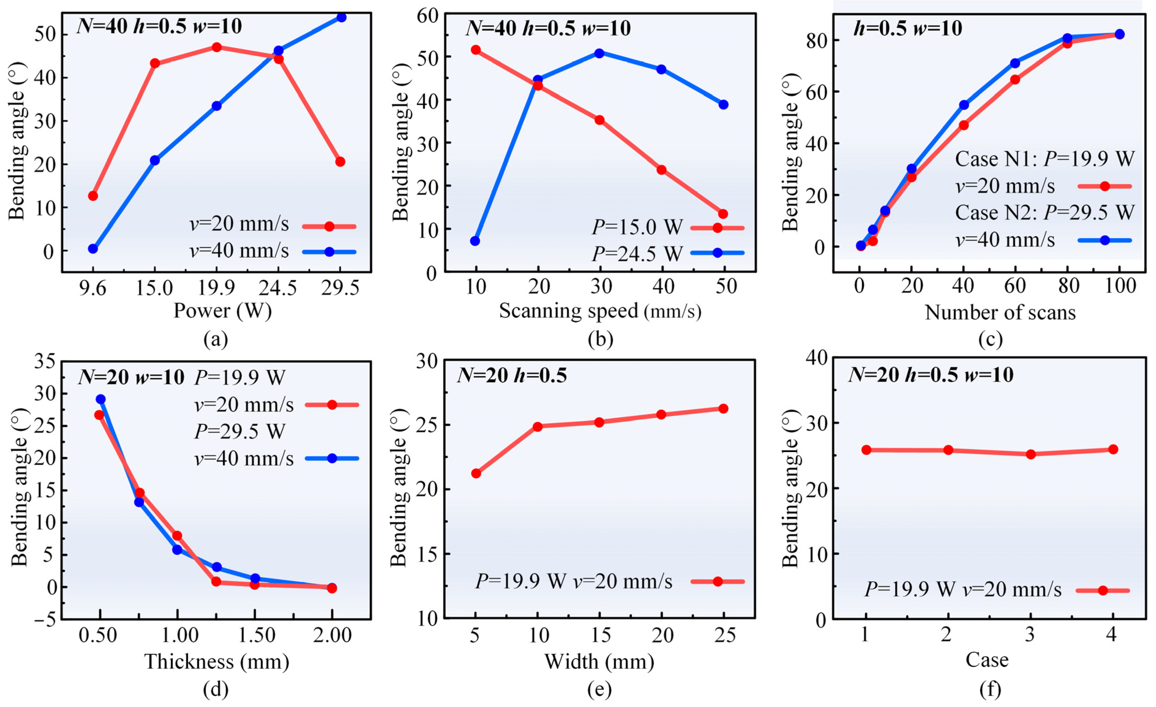
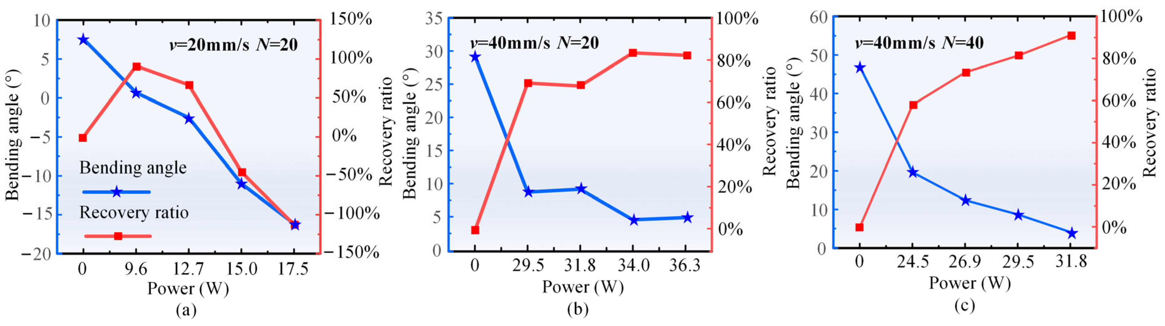
3.1. Effects of Process Parameters on the Bending Angle
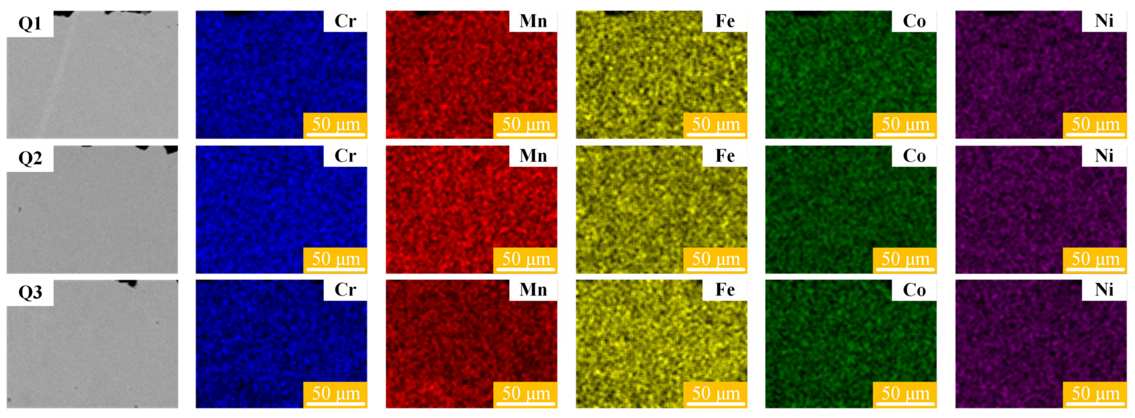
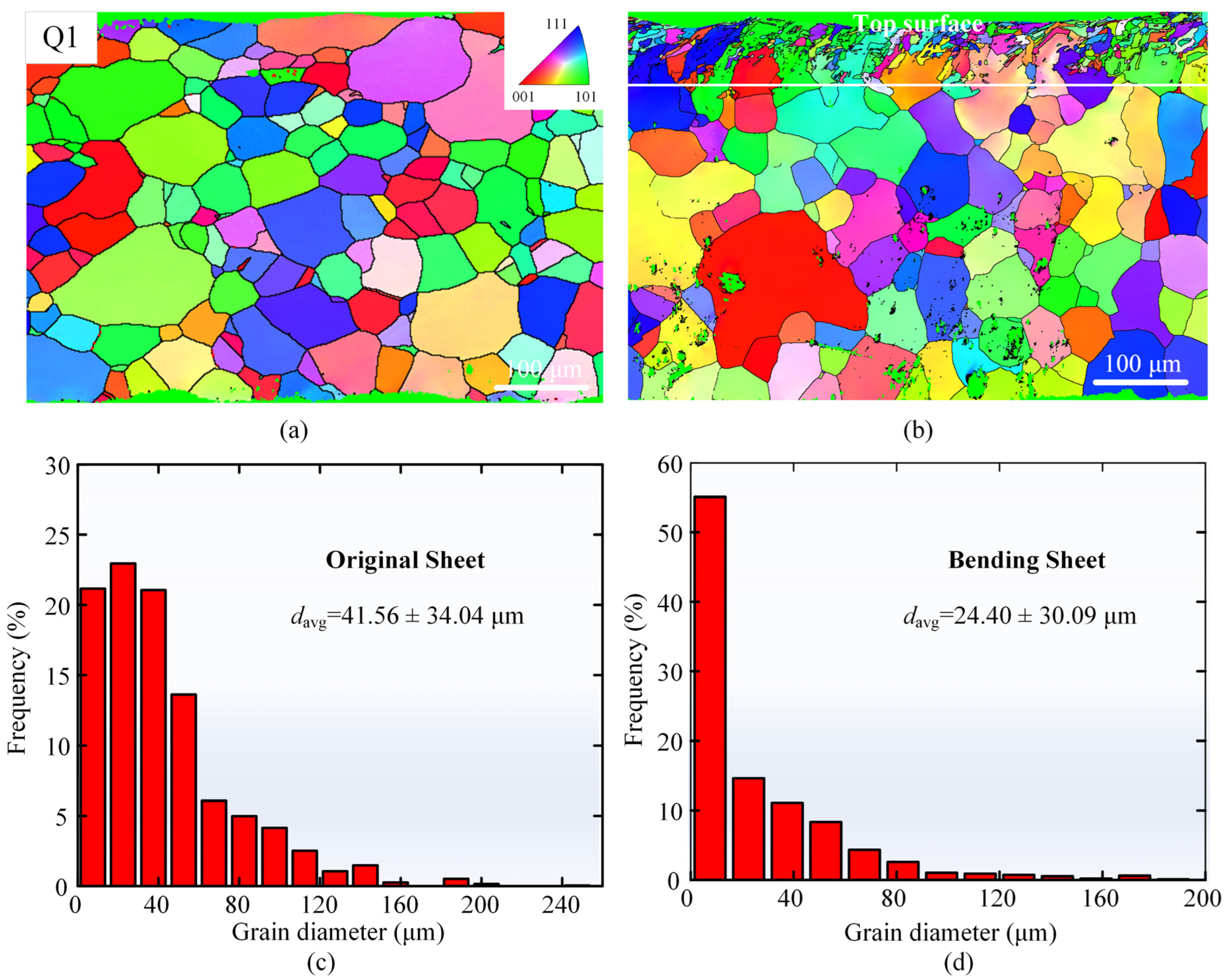
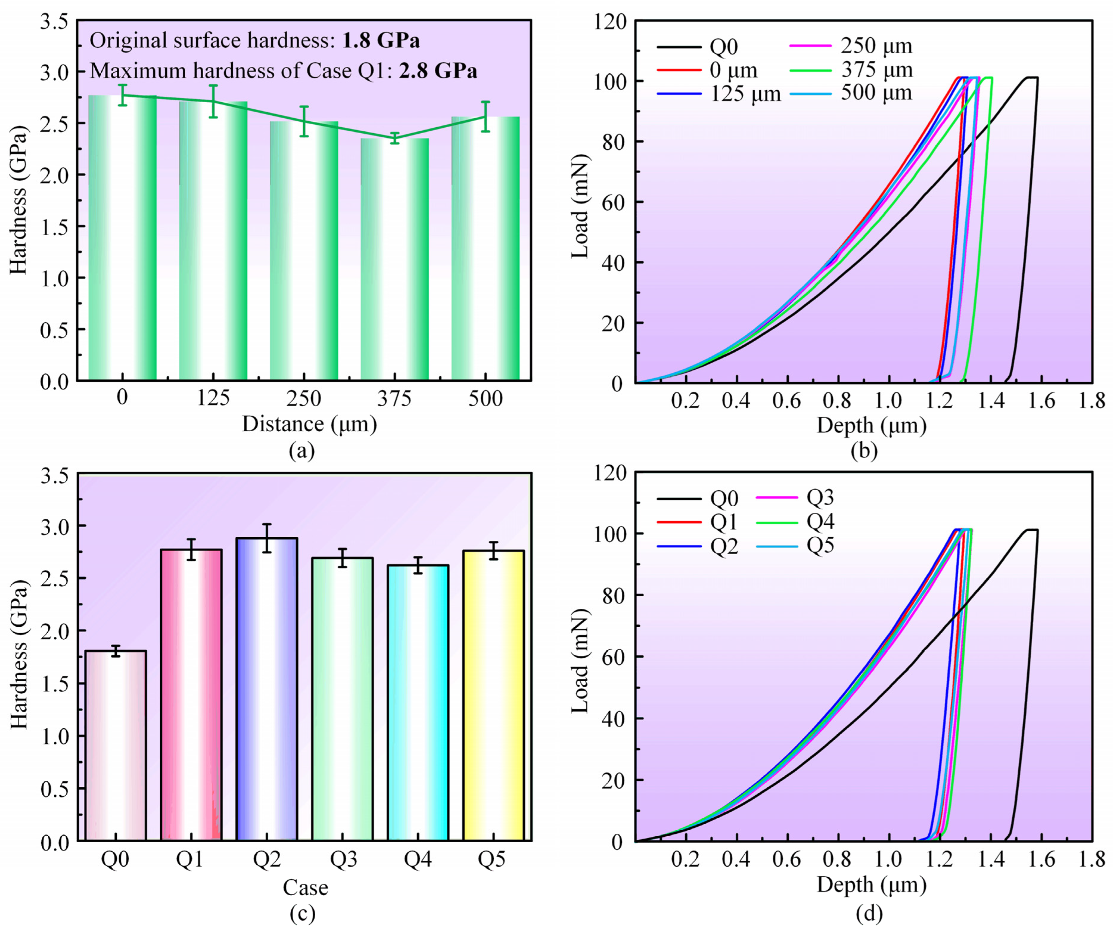
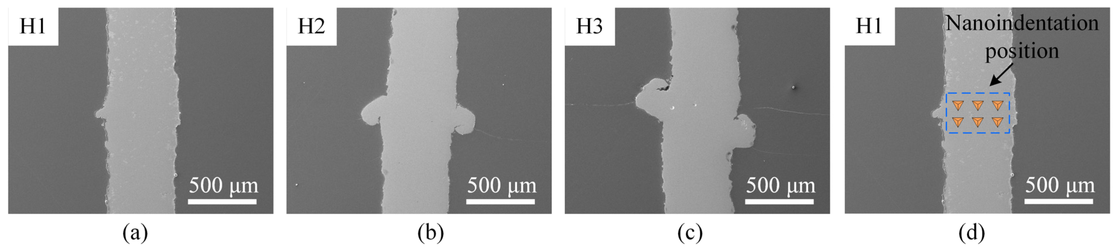
3.2. Evolution of the Microstructure and Hardness
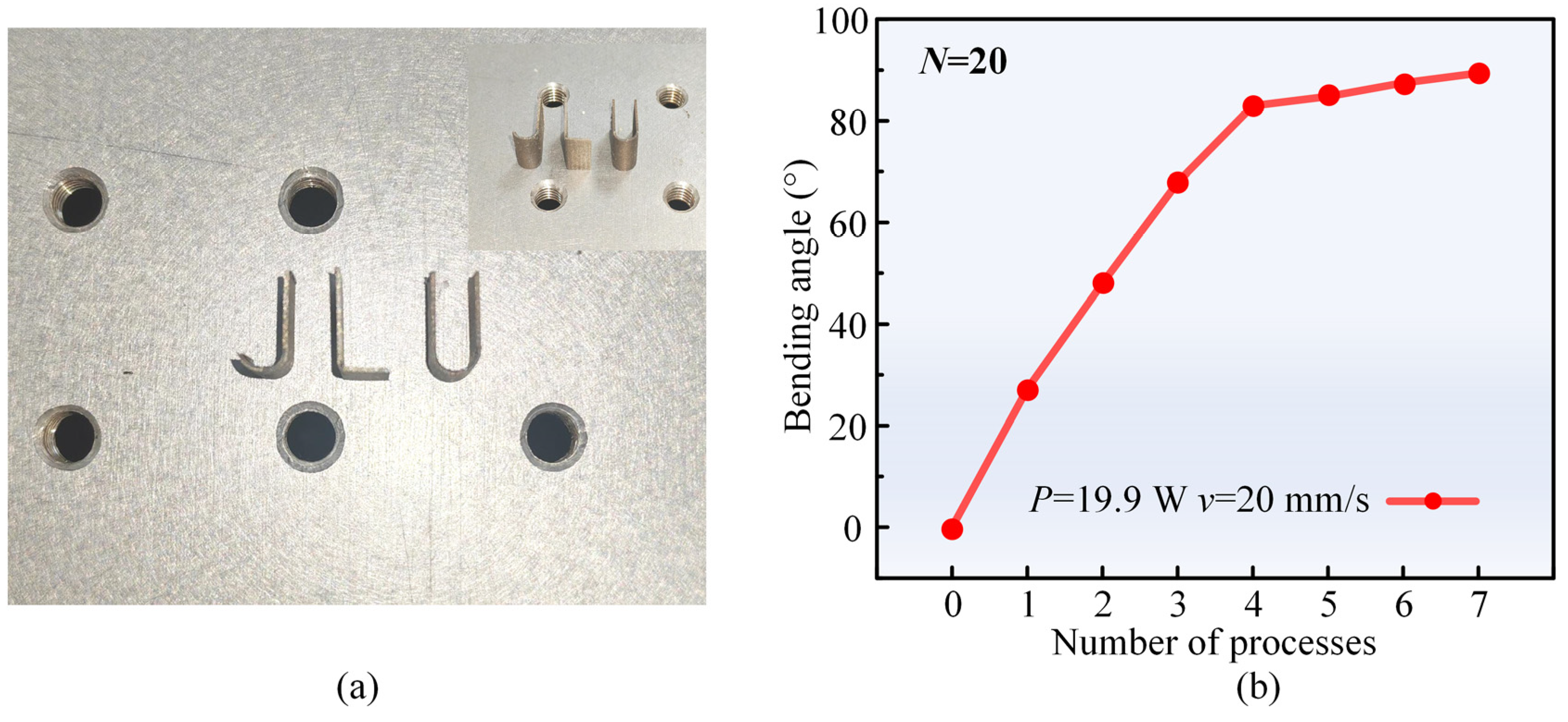
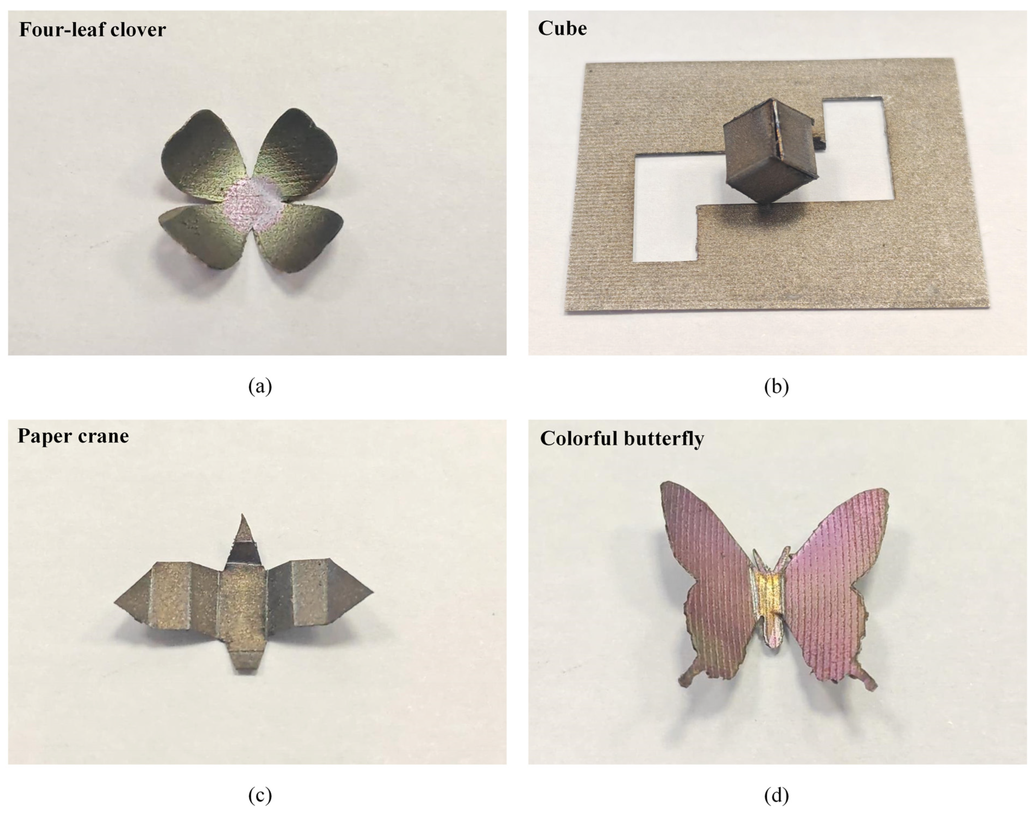
3.3. Application and Expansion of Laser Bending Forming
4. Conclusions
Author Contributions
Funding
Institutional Review Board Statement
Informed Consent Statement
Data Availability Statement
Conflicts of Interest
References
- Wang, Z.F.; Zhang, S. Research and Application Progress of High-Entropy Alloys. Coatings 2023, 13, 1916. [Google Scholar] [CrossRef]
- Fu, G.Q.; Liu, X.N.; Yi, X.Y.; Zhang, S.Z.; Cao, X.J.; Meng, X.L.; Gao, Z.Y.; Wang, H.Z. Development of High-Entropy Shape-Memory Alloys: A Review. Metals 2023, 13, 1279. [Google Scholar] [CrossRef]
- Cui, K.X.; Zhang, Y. High-Entropy Alloy Films. Coatings 2023, 13, 635. [Google Scholar] [CrossRef]
- Yue, W.; Fan, H.B.; Ru, W.A.; Wu, Z.X.; Zhang, Z.X.; Zhang, L.Y.; Ning, Z.L.; Sun, J.F.; Guo, S.; Huang, Y.J. In-situ study of room temperature tensile deformation of a CrMnFeCoNi high-entropy alloy. J. Alloys Compd. 2023, 940, 168904. [Google Scholar] [CrossRef]
- Wu, J.; Huang, G.Q.; Cao, F.J.; Sun, T.; Jiang, J.; Hu, J.P.; Shen, Z.K.; Hou, W.T.; Piao, Z.Y.; Feng, X.M.; et al. Insights into the microstructural evolution and wear behavior of underwater friction stir processed CoCrFeNiMn high-entropy alloy. Mater. Charact. 2023, 205, 113362. [Google Scholar] [CrossRef]
- Wang, H.D.; Kang, J.J.; Yue, W.; Jin, G.; Li, R.J.; Zhou, Y.K.; Liang, J.; Yang, Y.Y. Microstructure and Corrosive Wear Properties of CoCrFeNiMn High-Entropy Alloy Coatings. Materials 2023, 16, 55. [Google Scholar] [CrossRef] [PubMed]
- Shahmir, H.; Mehranpour, M.S.; Shams, S.A.A.; Langdon, T.G. Twenty years of the CoCrFeNiMn high-entropy alloy: Achieving exceptional mechanical properties through microstructure engineering. J. Mater. Res. Technol. 2023, 23, 3362–3423. [Google Scholar] [CrossRef]
- Kuzmin, A.; Pinchuk, V.; Arango, D.A.G.; Polo, O.C.C.; Pinchuk, S. Improving the thermal efficiency of small molding equipment to speed up the start of production and reduce energy consumption. Therm. Sci. Eng. Prog. 2023, 44, 102067. [Google Scholar] [CrossRef]
- Afshariantorghabeh, S.; Pesonen, A.; Kärki, T.; Leminen, V. Effects of thermoforming operation and tooling on the thermoformability of plastic-coated fibre-based materials. Packag. Technol. Sci. 2023, 36, 855–871. [Google Scholar] [CrossRef]
- Shao, H.; Wang, Y.L.; Wan, H.X.; Wang, H.B.; Zhang, Z.F.; Fu, W.Z. Research on springback compensation for multi-point forming of corrosion-resistant aluminum alloy hyperbolic component. Materia 2023, 28, e20220304. [Google Scholar] [CrossRef]
- Safari, M.; de Sousa, R.A.; Joudaki, J. Recent Advances in the Laser Forming Process: A Review. Metals 2020, 10, 1472. [Google Scholar] [CrossRef]
- Bachmann, A.L.; Dickey, M.D.; Lazarus, N. Making Light Work of Metal Bending: Laser Forming in Rapid Prototyping. Quantum Beam Sci. 2020, 4, 44. [Google Scholar] [CrossRef]
- Yadav, R.; Yadav, R.; Kant, R. Experimental study on laser bending of mild steel with buckling mechanism. Opt. Laser Technol. 2023, 167, 109803. [Google Scholar] [CrossRef]
- Shen, H.; Vollertsen, F. Modelling of laser forming—An review. Comp. Mater. Sci. 2009, 46, 834–840. [Google Scholar] [CrossRef]
- Shen, H. Mechanism of laser micro-adjustment. J. Phys. D Appl. Phys. 2008, 41, 245106. [Google Scholar] [CrossRef]
- Pirch, N.; Wissenbach, K. Mechanisms during laser bending. J. Laser Appl. 2008, 20, 135–139. [Google Scholar] [CrossRef]
- Liu, C.; Yao, Y.L.; Srinivasan, V. Optimal process planning for laser forming of doubly curved shapes. J. Manuf. Sci. Eng. 2004, 126, 1–9. [Google Scholar] [CrossRef]
- Li, W.C.; Yao, Y.L. Laser bending of tubes: Mechanism, analysis, and prediction. J. Manuf. Sci. Eng. 2001, 123, 674–681. [Google Scholar] [CrossRef]
- Cheng, P.; Fan, Y.J.; Zhang, J.; Yao, Y.L.; Mika, D.P.; Zhang, W.W.; Graham, M.; Marte, J.; Jones, M. Laser forming of varying thickness plate—Part I: Process analysis. J. Manuf. Sci. Eng. 2006, 128, 634–641. [Google Scholar] [CrossRef]
- Ghoreishi, S.R.; Mahmoodi, M. On the laser forming process of copper/aluminum bi-metal sheets with a functional thickness. Opt. Laser Technol. 2022, 149, 107870. [Google Scholar] [CrossRef]
- Changdar, A.; Shrivastava, A.; Chakraborty, S.S.; Dutta, S. Investigation on laser forming of open cell aluminum foam. J. Laser Appl. 2022, 34, 032009. [Google Scholar] [CrossRef]
- Mazdak, S.; Sheykholeslami, M.R.; Gholami, M.; Parvaz, H.; Najafizadeh, M.M.; Mahmoudi, S.; Vanaki, A. A statistical model for estimation of bending angle in laser bending of two-layer steel-aluminum sheets. Opt. Laser Technol. 2023, 157, 108575. [Google Scholar] [CrossRef]
- Liu, J.; Sun, S.; Guan, Y.J. Numerical investigation on the laser bending of stainless steel foil with pre-stresses. J. Mater. Process. Technol. 2009, 209, 1580–1587. [Google Scholar] [CrossRef]
- Hu, Z.; Kovacevic, R.; Labudovic, M. Experimental and numerical modeling of buckling instability of laser sheet forming. Int. J. Mach. Tools Manuf. 2002, 42, 1427–1439. [Google Scholar] [CrossRef]
- Liu, J.; Sun, S.; Guan, Y.J.; Ji, Z. Experimental study on negative laser bending process of steel foils. Opt. Laser Eng. 2010, 48, 83–88. [Google Scholar] [CrossRef]
- Shi, Y.J.; Liu, Y.C.; Yi, P.; Hu, J. Effect of different heating methods on deformation of metal plate under upsetting mechanism in laser forming. Opt. Laser Technol. 2012, 44, 486–491. [Google Scholar] [CrossRef]
- Shi, Y.J.; Yao, Z.Q.; Shen, H.; Hu, J. Research on the mechanisms of laser forming for the metal plate. Int. J. Mach. Tools Manuf. 2006, 46, 1689–1697. [Google Scholar] [CrossRef]
- Shi, Y.J.; Guo, Y.K.; Wang, X.G.; Wang, S.Y.; Zhao, X.Y. Laser bending angle and deformation mechanism under different auxiliary loads. Opt. Laser Technol. 2022, 156, 108517. [Google Scholar] [CrossRef]
- Bachmann, A.L.; Hanrahan, B.; Dickey, M.D.; Lazarus, N. Self-Folding PCB Kirigami: Rapid Prototyping of 3D Electronics via Laser Cutting and Forming. ACS Appl. Mater. Interfaces 2022, 14, 14774–14782. [Google Scholar] [CrossRef]
- Abedinzadeh, R.; Sattari, M.; Toghraie, D. Experimental Analysis on Bending Behavior of Non-Alloy Carbon Steel Sheets Using Laser-Forming Process. Steel Res. Int. 2022, 93, 2200011. [Google Scholar] [CrossRef]
- Khandai, B.K.; Shukla, S.; Muvvala, G. Investigating the effect of laser modulation and input energy on bending mechanism and bending angle in the multi-pass laser forming process through real-time monitoring. Opt. Laser Technol. 2024, 169, 110100. [Google Scholar] [CrossRef]
- Chen, D.J.; Wu, S.C.; Li, M.Q. Studies on laser forming of Ti-6Al-4V alloy sheet. J. Mater. Process. Technol. 2004, 152, 62–65. [Google Scholar] [CrossRef]
- Chen, G.F.; Xu, X.F. Experimental and 3D finite element studies of CW laser forming of thin stainless steel sheets. J. Manuf. Sci. Eng. 2001, 123, 66–73. [Google Scholar] [CrossRef]
- Maji, K.; Pratihar, D.K.; Nath, A.K. Experimental investigations and statistical analysis of pulsed laser bending of AISI 304 stainless steel sheet. Opt. Laser Technol. 2013, 49, 18–27. [Google Scholar] [CrossRef]
- Santos, E.C.; Morita, M.; Shiomi, M.; Osakada, K.; Takahashi, M. Laser gas nitriding of pure titanium using CW and pulsed Nd:YAG lasers. Surf. Coat. Technol. 2006, 201, 1635–1642. [Google Scholar] [CrossRef]
- Yaakob, K.I.; Ishak, M.; Quazi, M.M.; Salleh, M.N.M. Optimizing the pulse wave mode low power fibre laser welding parameters of 22Mnb5 boron steel using response surface methodology. Measurement 2019, 135, 452–466. [Google Scholar] [CrossRef]
- Lazarus, N.; Bedair, S.S.; Smith, G.L. Origami Inductors: Rapid Folding of 3-D Coils on a Laser Cutter. IEEE Electron Device Lett. 2018, 39, 1046–1049. [Google Scholar] [CrossRef]
- Yadav, R.; Goyal, D.K.; Kant, R. A comprehensive study on the effect of line energy during laser bending of duplex stainless steel. Opt. Laser Technol. 2022, 151, 108025. [Google Scholar] [CrossRef]
- Hussain, M.; Gupta, A.; Kumar, P.; Hussain, M.I.; Das, A.K. Experimental study and statistical analysis of bending titanium alloy sheet with continuous wave fiber laser. Arch. Civ. Mech. Eng. 2022, 22, 110. [Google Scholar] [CrossRef]
- Sharma, Y.P.; Kant, R.; Sidhu, B.S.; Yadav, R. Mechanical behaviour of mild steel during multi-scan laser bending with forced cooling. Opt. Laser Technol. 2024, 171, 110417. [Google Scholar] [CrossRef]
- Seyedkashi, S.M.H.; Abazari, H.D.; Gollo, M.H.; Woo, Y.Y.; Moon, Y.H. Characterization of laser bending of SUS304L/C11000 clad sheets. J. Mech. Sci. Technol. 2019, 33, 3223–3230. [Google Scholar] [CrossRef]
- Paunoiu, V.; Squeo, E.A.; Quadrini, F.; Gheorghies, C.; Nicoara, D. Laser Bending of Stainless Steel Sheet Metals. Int. J. Mater. Form. 2008, 1, 1371–1374. [Google Scholar] [CrossRef]
- Yang, L.J.; Tang, J.; Wang, M.L.; Wang, Y.; Chen, Y.B. Surface characteristic of stainless steel sheet after pulsed laser forming. Appl. Surf. Sci. 2010, 256, 7018–7026. [Google Scholar] [CrossRef]
- Maji, K.; Pratihar, D.K.; Nath, A.K. Experimental investigations; modeling, and optimization of multi-scan laser forming of AISI 304 stainless steel sheet. Int. J. Adv. Manuf. Technol. 2016, 83, 1441–1455. [Google Scholar] [CrossRef]
- Guo, L.; Cai, P.; Wang, H.; Chen, Y.; Zhang, Q.M.; Xu, Q. Experimental study of pulsed laser bending process parameters of 6061 aluminum alloy sheet. Mater. Res. Express 2019, 6, 046526. [Google Scholar] [CrossRef]
- Chan, K.C.; Yau, C.L.; Lee, W.B. Laser bending of thin stainless steel sheets. J. Laser Appl. 2000, 12, 34–40. [Google Scholar] [CrossRef]
- Nunobiki, M.; Okuda, K.; Hourai, K.; Shizuka, H. Bending of Pure Titanium Sheet to Curved Surface Shape by Laser Forming Technique. Adv. Mater. Res. 2010, 128, 388–393. [Google Scholar] [CrossRef]
- Nikolov, G.N.; Thomsen, A.N.; Kristiansen, M. Hardening in laser forming under the temperature gradient mechanism. IOP Conf. Ser. Mater. Sci. Eng. 2021, 1135, 012006. [Google Scholar] [CrossRef]
- Yadav, R.; Goyal, D.K.; Kant, R. Enhancing process competency by forced cooling in laser bending process. J. Therm. Stresses 2022, 45, 617–629. [Google Scholar] [CrossRef]
- Chakraborty, S.S.; More, H.; Racherla, V.; Nath, A.K. Modification of bent angle of mechanically formed stainless steel sheets by laser forming. J. Mater. Process. Technol. 2015, 222, 128–141. [Google Scholar] [CrossRef]
- Zhang, H.Y.; Qian, Y.F.; Zhang, L.; Jiang, M.Q.; Huang, H.; Yan, J.W. Significant improvement in surface hardness of Zr-based metallic glass by nanosecond pulsed laser irradiation in graphite powder water suspension. Surf. Coat. Technol. 2023, 454, 129195. [Google Scholar] [CrossRef]
- Wang, C.; Hong, J.; Cui, M.M.; Huang, H.; Zhang, L.; Yan, J.W. The effects of simultaneous laser nitriding and texturing on surface hardness and tribological properties of Ti6Al4V. Surf. Coat. Technol. 2022, 437, 128358. [Google Scholar] [CrossRef]


| Materials | CoCrFeMnNi HEA |
|---|---|
| Laser power, P (W) | 9.6, 15.0, 19.9, 24.5, 29.5 |
| Scanning speed, v (mm/s) | 10, 20, 30, 40, 50 |
| Number of scans, N | 1, 5, 10, 20, 40, 60, 80, 100 |
| Sheet thickness, h (mm) | 0.5, 0.75, 1.00, 1.25, 1.50, 2.00 |
| Sheet width, w (mm) | 5, 10, 15, 20, 25 |
| Materials | CoCrFeMnNi HEA |
|---|---|
| Sheet size (mm3) | 30 × 10 × 0.5 |
| Scanning area size (mm2) | 11 × 3 |
| Laser power, P (W) | 19.9, 24.5, 29.5, 34, 38.6 |
| Scanning speed, v (mm/s) | 70, 80, 90, 100, 110 |
| Scanning interval, L (mm) | 0.025, 0.03, 0.035, 0.04, 0.045 |
| Case | Laser Power | Scanning Speed | Number of Scans | Bending Angle |
|---|---|---|---|---|
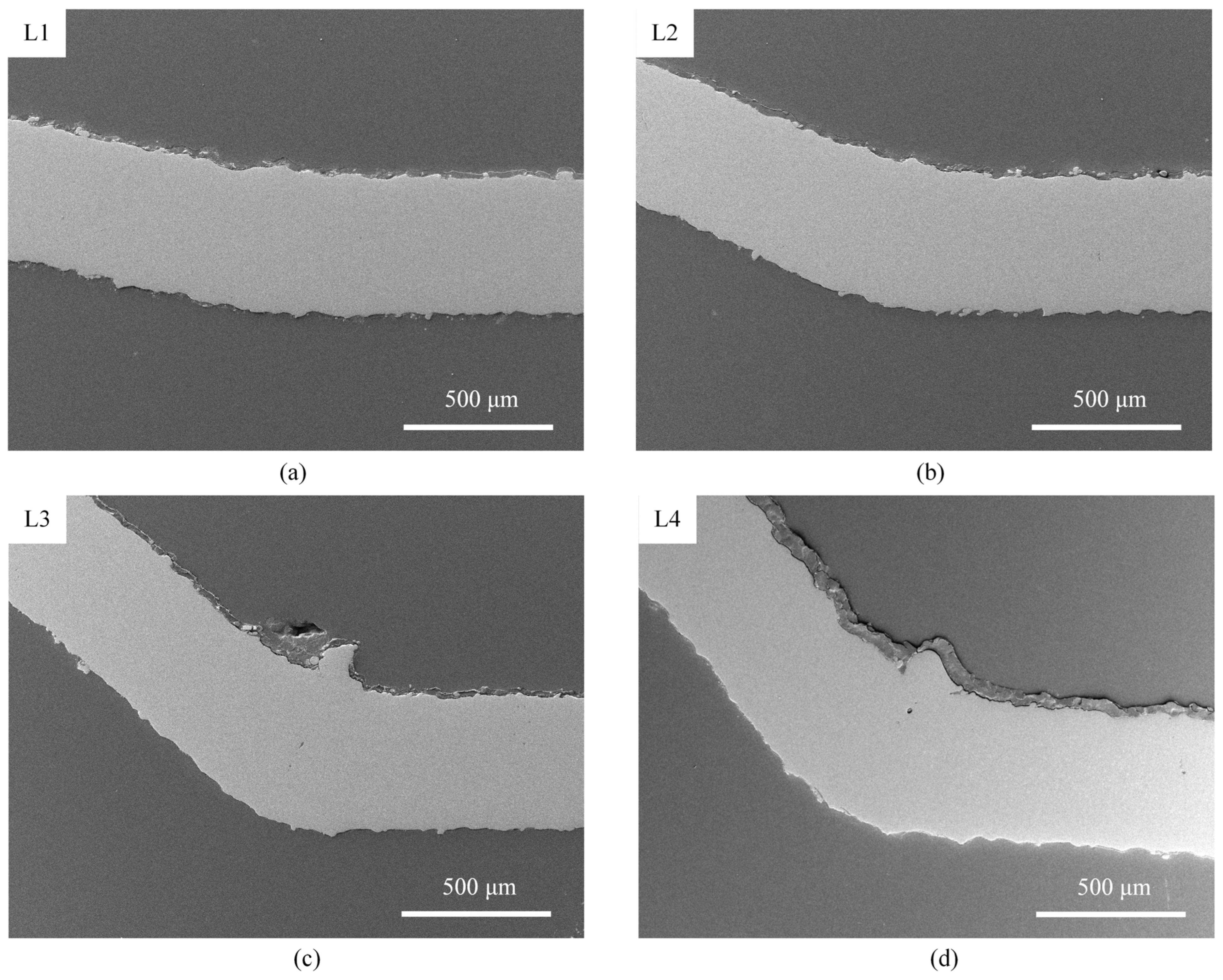
| L1 | 15.0 W | 40 mm/s | 20 | 13.7° |
| L2 | 15.0 W | 40 mm/s | 40 | 23.6° |
| L3 | 15.0 W | 20 mm/s | 40 | 43.1° |
| L4 | 24.5 W | 40 mm/s | 40 | 47.0° |
| Case | Laser Power | Scanning Speed | Scanning Interval | Bending Angle |
|---|---|---|---|---|
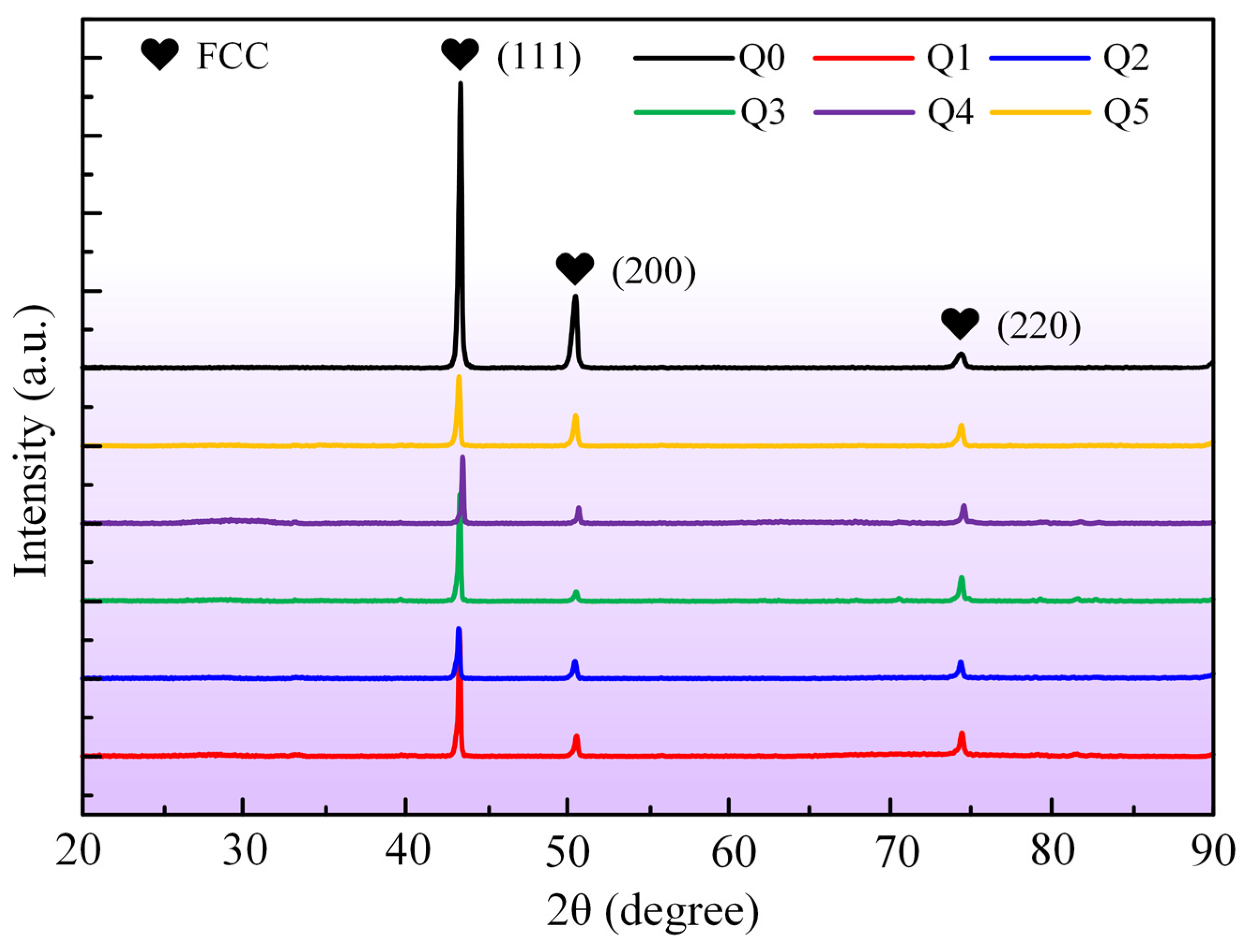
| Q1 | 29.5 W | 90 mm/s | 0.035 mm | 46.3° |
| Q2 | 29.5 W | 90 mm/s | 0.025 mm | 78.7° |
| Q3 | 29.5 W | 90 mm/s | 0.045 mm | 21.7° |
| Q4 | 19.9 W | 90 mm/s | 0.035 mm | 12.9° |
| Q5 | 38.6 W | 90 mm/s | 0.035 mm | 76.4° |
| Part | Laser Power | Scanning Speed | Number of Scans/ Scanning Interval | Number of Processes |
|---|---|---|---|---|
| L | 19.9 W | 20 mm/s | 20 | 7 |
| J, U | 31.8 W (1), 34.0 W (2) | 90 mm/s | 0.03 mm | 2 |
| Case | Laser Power | Scanning Speed | Number of Scans | Bending Angle |
|---|---|---|---|---|
| H1 | 9.6 W | 20 mm/s | 20 | 7.6° |
| H2 | 29.5 W | 40 mm/s | 20 | 29.3° |
| H3 | 24.5 W | 40 mm/s | 40 | 47.0° |
Disclaimer/Publisher’s Note: The statements, opinions and data contained in all publications are solely those of the individual author(s) and contributor(s) and not of MDPI and/or the editor(s). MDPI and/or the editor(s) disclaim responsibility for any injury to people or property resulting from any ideas, methods, instructions or products referred to in the content. |
© 2024 by the authors. Licensee MDPI, Basel, Switzerland. This article is an open access article distributed under the terms and conditions of the Creative Commons Attribution (CC BY) license (https://creativecommons.org/licenses/by/4.0/).
Share and Cite
Tian, X.; Wang, C.; Zhang, H.; Gao, J.; Huang, H.; Yan, J. Bending Forming Characteristics of CoCrFeMnNi High-Entropy Alloy Sheets Induced by Nanosecond Pulse Laser Irradiation. Materials 2024, 17, 3728. https://doi.org/10.3390/ma17153728
Tian X, Wang C, Zhang H, Gao J, Huang H, Yan J. Bending Forming Characteristics of CoCrFeMnNi High-Entropy Alloy Sheets Induced by Nanosecond Pulse Laser Irradiation. Materials. 2024; 17(15):3728. https://doi.org/10.3390/ma17153728
Chicago/Turabian StyleTian, Xinyu, Chao Wang, Hongyang Zhang, Junfeng Gao, Hu Huang, and Jiwang Yan. 2024. "Bending Forming Characteristics of CoCrFeMnNi High-Entropy Alloy Sheets Induced by Nanosecond Pulse Laser Irradiation" Materials 17, no. 15: 3728. https://doi.org/10.3390/ma17153728
APA StyleTian, X., Wang, C., Zhang, H., Gao, J., Huang, H., & Yan, J. (2024). Bending Forming Characteristics of CoCrFeMnNi High-Entropy Alloy Sheets Induced by Nanosecond Pulse Laser Irradiation. Materials, 17(15), 3728. https://doi.org/10.3390/ma17153728