Abstract
Planar perovskite solar cells (PSCs), as a promising photovoltaic technology, have been extensively studied, with strong expectations for commercialization. Improving the power conversion efficiency (PCE) of PSCs is necessary to accelerate their practical application, in which the electron transport layer (ETL) plays a key part. Herein, a single-anchored ligand of phenylphosphonic acid (PPA) is utilized to regulate the chemical bath deposition of a TiO2 ETL, further improving the PCE of planar PSCs. The PPA possesses a steric benzene ring and a phosphoric acid group, which can inhibit the particle aggregation of the TiO2 film through steric hindrance, leading to optimized interface (ETL/perovskite) contact. In addition, the incorporated PPA can induce the upshift of the Fermi-level of the TiO2 film, which is beneficial for interfacial electron transport. As a consequence, the PSCs with PPA-TiO2 achieve a PCE of 24.83%, which is higher than that (24.21%) of PSCs with TiO2. In addition, the unencapsulated PSCs with PPA-TiO2 also exhibit enhanced stability when stored in ambient conditions.
1. Introduction
Metal halide perovskite solar cells (PSCs) show huge potential in capturing and converting solar energy efficiently due to distinguishing advantages like low-cost solution preparation, high efficiency, and so on [1,2]. In 2009, PSCs were first reported with a power conversion efficiency (PCE) of 3.8% [3].
After massive efforts from the perspective of experimental and theory calculations on PSCs over the past years, researchers have achieved a substantial improvement in the performance of PSCs by developing a variety of optimization strategies, with the latest PCE certification rate of 26.14% [4]. However, compared to the Shockley–Queisser limit, there is still much room for PCE improvement. As a multilayered structure, the PCE is a comprehensive factor of PSCs, and it is related to all the function layers and their cooperation [5,6]. Among the function layers in n-i-p planar PSCs, the electron transport layer (ETL) plays a vital part in the PCE, since it not only extracts the photo-generated electron but also serves as a substrate for perovskite film deposition [7,8]. Hence, optimizing ETL properties and further exploring its underlying mechanism on PSC physical characteristics is supposed to be a feasible approach to improve the PCE of PSCs.
Among the efficient planar PSCs, one of the popular ETLs is titanium dioxide (TiO2), which was applied to PSCs in the initial stage of PSC research [9,10,11,12]. In order to obtain a TiO2 ETL that can help achieve high-performance PSCs, researchers have developed preparation methods such as spin-coating, magnetron sputtering, and chemical bath deposition (CBD) [13,14,15]. Among them, CBD possesses the advantage of low-temperature deposition and conformal deposition, which is suitable for the light-managing textured substrate of FTO [16,17,18]. As early as 2019, Cui et al. [19] applied TiO2 prepared using CBD as an ETL, realizing a PCE of up to 21.88% in a planar PSC. In 2022, although combining the surface modification of TiO2 deposited using CBD and perovskite crystallization regulation, Li et al. [20] achieved a PCE of 24.5% but did not reach their limit value. Further breakthroughs can be achieved, especially considering that SnO2-based PSCs have achieved a certificated PCE of more than 25% in the same term. In fact, in the CBD process of TiO2, the hydrolysis activation energy of TiCl4 is low, and the reaction easily occurs. Accompanied by a large amount of exothermic and hydrochloric acid gas, the reaction process is very rapid, and a large number of TiO2 particles are generated and agglomerate in a short time, resulting in the formation of TiO2 films with a large number of oxygen vacancies with a rough morphology [21,22]. These vacancy defects and surface particle aggregation restrict PCE improvement through carrier recombination and inferior TiO2/perovskite interfacial contact properties [23]. Hence, it is necessary to regulate CBD and explore the functional mechanism of the regulation of TiO2 properties, realizing a high-quality TiO2 ETL to improve the photovoltaic performance of planar PSCs.
Herein, we regulated TiO2 CBD by incorporating phenylphosphonic acid (PPA; its molecular structure formula is shown in Figure S1) into a bath precursor mixed with TiCl4 and deionized water. The regulated TiO2 is named PPA-TiO2. The PPA possesses a steric benzene ring and a phosphoric acid group, which can interact with TiO2, achieving the inhibition of particle aggregation through steric hindrance. Additionally, the deposition regulation using PPA induces an upshift of the Fermi level of TiO2, optimizing interface energy level matching. After deposition regulation, the corresponding planar PSCs possess enhanced electron transport, which should result from the modified matching of the interfacial energy level and optimized interfacial contact property resulting from a smooth TiO2 surface. As a consequence, the PSCs with PPA-TiO2 achieve a champion PCE of 24.83%, which is higher than that (24.21%) of PSCs with TiO2. In addition, PSCs with PPA-TiO2 also exhibit enhanced storage stability.
2. Results and Discussion
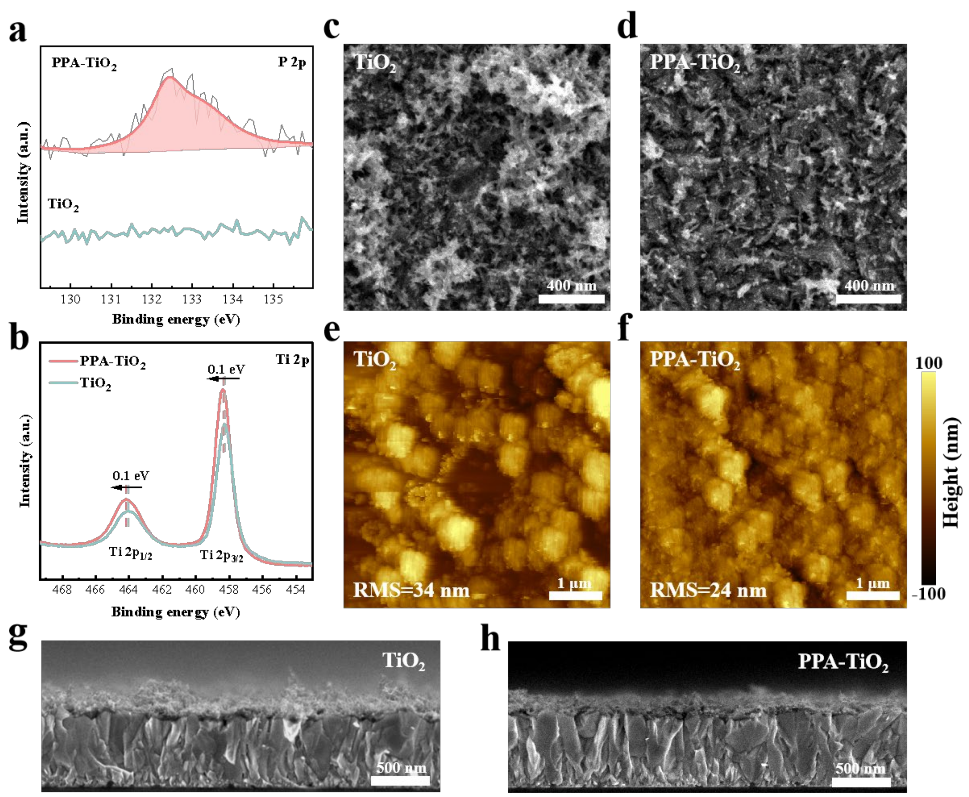
CBD is a common method to deposit metal oxide films such as TiO2, tin dioxide (SnO2), and so on [24,25]. In this work, we utilized CBD to deposit a TiO2 film with the experimental parameters based on our previous reports [19]. First, we prepared the bath precursor by mixing the TiCl4 and deionized water. Then, we immersed the cleaned substrate into the precursor to grow the film. For regulating CBD, we introduced PPA as a representative example into the chemical bath precursor before the subsequent film growth. Figure S1 shows the molecular structure formula of PPA, which has a phosphoric acid group that can be used as a ligand to coordinate with TiO2 to regulate the deposition process. First, we carried out X-ray photoelectron spectroscopy (XPS) measurements on the TiO2 and PPA-TiO2 films to obtain the surface elements and chemical states. As shown in Figure 1a, we can obviously observe the P 2p peaks near 132.5 eV on the PPA-TiO2 films, indicating the successful incorporation of PPA. Meanwhile, as shown in Figure 1b, the binding energies of the Ti 2p1/2 and Ti 2p3/2 peaks of the TiO2 ETL and PPA-TiO2 ETL are 464.09 and 458.27 eV and 464.19 and 458.37 eV, respectively. The shift of the Ti 2p peaks to higher binding energies indicates that PPA can form a chemical interaction with Ti. This interaction between PPA and TiO2 can be utilized to regulate the chemical bath process.
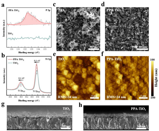
Figure 1.
Characterization of the ETLs. (a) XPS spectra of P 2p for the ETLs. (b) XPS spectra of Ti 2p for the ETLs. (c,d) Surface SEM images of the ETLs. (e,f) AFM images of the ETLs. (g,h) Cross-sectional SEM images of the ETLs.
The influence of PPA on the TiO2 morphology was characterized using scanning electron microscope (SEM) and atomic force microscope (AFM) measurements. As shown in Figure 1c,d, the particle aggregation of TiO2 can be clearly observed, which was a rough topography. The poor surface morphology caused by the aggregation of the TiO2 particles would affect the electrical conductivity and interface contact between TiO2 and the perovskite film. In comparison, the PPA-TiO2 surface was relatively flat and smooth without obvious particle aggregation, which realizes conformal coverage on the FTO substrate. The AFM images of TiO2 and PPA-TiO2 are shown in Figure 1e,f. It can be found that there are some bright sites in the AFM image of TiO2, indicating existing particle aggregation, which is consistent with the SEM image (Figure 1c). As a comparison, the PPA-TiO2 was flatter with uniformly dispersed particles. Furthermore, the root mean square (RMS) of the surface topography height was calculated to analyze the surface roughness of the TiO2 and PPA-TiO2 films quantitatively. The RMS of PPA-TiO2 was 24 nm, which is obviously lower than that of TiO2 (34 nm), indicating the inhibition of particle aggregation on the film surface. The cross-sectional SEM images of the TiO2 film and PPA-TiO2 film are shown in Figure 1g,h. In Figure 1g, we can observe that the TiO2 film yields a rough surface, and due to the formation of agglomeration, it shows sharp ups and downs in different positions. In Figure 1h, it is observed that the PPA-TiO2 film maintains a relatively flat morphology in the entire section without particularly violent height fluctuations, and the entire layer of TiO2 appears very dense and smooth, which confirms its inhibitory effect on particle aggregation. The optical transmittance spectra of the TiO2 film and PPA-TiO2 film are shown in Figure S2, and the results show that the flatter surface also helps to reduce the scattering of incident light by the ETL, especially in the wavelength range of 320–380 nm, which helps to enhance the absorption of light by the perovskite light absorption layer.
Next, we investigated the influence of PPA on the electrical properties and energy level structure of the TiO2 films. Conductive atomic force microscopy (C-AFM) was used to evaluate the conductivity and the lateral uniformity. C-AFM uses a probe to conduct contact scanning with the sample surface and apply a bias voltage to generate Coulomb repulsion between atoms, obtain surface morphology and current intensity signals, and obtain nanoscale J–V curves of the film surface with an atomic-level resolution. It can be seen from Figure 2a,b that in addition to the significantly improved current, the PPA-TiO2 film obtained better uniformity in terms of current distribution. The J–V curves also reflect that the PPA-TiO2 film had optimized electrical conductivity (Figure 2c). Kelvin probe force microscopy (KPFM) measurements were used to detect the surface potentials of the films (Figure 2d,e). Compared with TiO2, the PPA-TiO2 film showed lower surface potential, suggesting a higher Fermi level (EF), which is favorable for interfacial electron transport. We also carried out an ultraviolet photoelectron spectroscopy (UPS) test to characterize the energy level structure of the TiO2 film and PPA-TiO2 film. Combining the results of the UPS and Tauc plots (Figures S3 and S4), we calculated the valence band maximum energy (EVBM) of the TiO2 film and PPA-TiO2 film to be −8.11 and −7.79 eV, respectively, and the conduction band minimum energy (ECBM) of the TiO2 film and PPA-TiO2 film to be −4.66 and −4.37 eV, respectively (Figure 2f). Compared to the TiO2 film, the EF of the PPA-TiO2 film rose from −5.13 to −5.12 eV, and the ECBM of the PPA-TiO2 film rose from −4.66 to −4.37 eV, which is conducive to optimizing interfacial electron transport and decreasing interfacial electron accumulation.
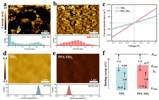
Figure 2.
Characterization of the ETLs. (a,b) C-AFM images of the TiO2 and PPA-TiO2 films. The statistical current distributions of the film surfaces are shown at the bottom. (c) J–V curves of the devices structured as FTO/ETLs/Au. (d,e) Surface potential images of the TiO2 and PPA-TiO2 films. The statistical potential distributions of the film surfaces are shown at the bottom. (f) Energy level diagram of TiO2 and PPA-TiO2.
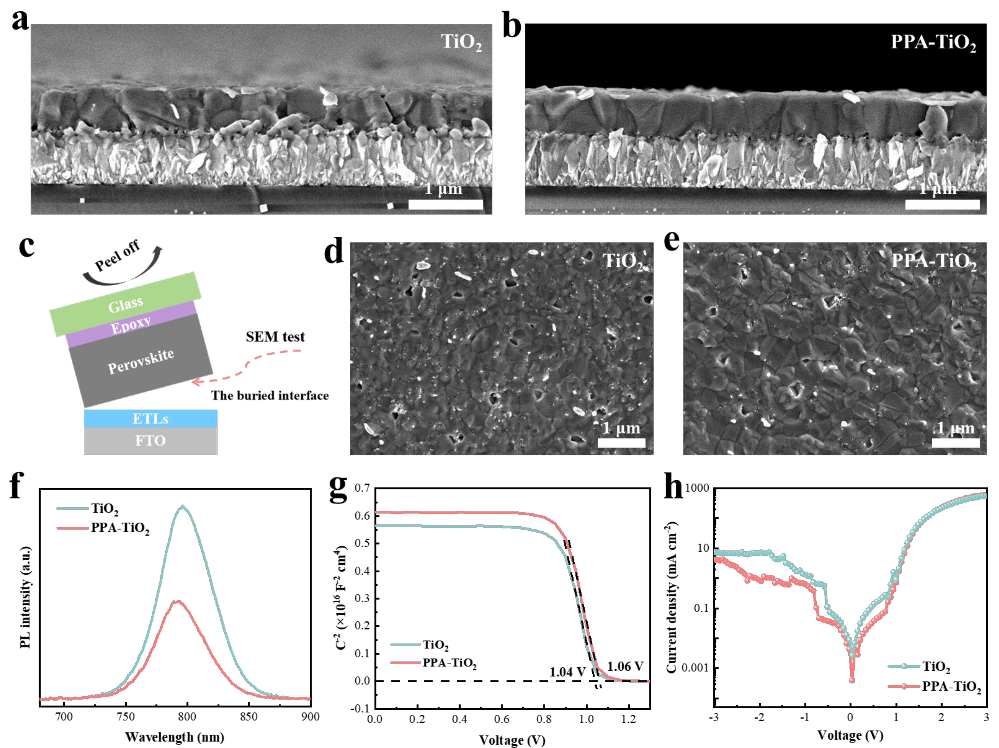
Since TiO2 is an ETL in n-i-p planar PSCs in which the ETL serves as the substrate for perovskite deposition, the surface topography of the TiO2 film has a significant effect on the crystallization growth process of the upper perovskite, thus affecting the quality of the perovskite film. To characterize the perovskite films fabricated on TiO2 and PPA-TiO2, we applied cross-sectional SEM, with the results shown in Figure 3a,b. Compared with the TiO2-based perovskite film, the perovskite film grown on PPA-TiO2 had a larger grain size with a uniform orientation, which should be attributed to the inhibited surface particle aggregation. In order to more directly observe the contact between the ETLs and perovskite and the growth of perovskite at the bottom, we performed SEM tests on the buried perovskite films by exposing the buried interface. The method of exposing the buried interface is shown in Figure 3c. We first used an epoxy adhesive to tighten the adhesion glass and the surface of the perovskite film. Due to the loose contact between the ETL and the buried perovskite, the buried interface of the perovskite film could be exposed through the holistic stripping of the glass and perovskite film. It can be clearly seen from Figure 3d,e that the buried interface of perovskite showed a smaller grain size based on the TiO2 ETL, while the perovskite film had a larger grain size based on PPA-TiO2, which is consistent with the cross-section SEM, indicating that PPA-TiO2 contributes to the crystal growth of perovskite. More importantly, there were a large number of TiO2 dendrites attached to the buried interface based on the TiO2 ETL, and there were more holes. In contrast, the buried interface based on the PPA-TiO2 ETL had fewer TiO2 dendrites and holes. This obvious difference can be attributed to the existence of a large number of loose TiO2 dendrite aggregation structures on the surface of the TiO2 ETL, and the use of PPA for deposition regulation could effectively control the deposition process of TiO2, reduce the generation of TiO2 dendrites, and achieve the tight deposition of TiO2 based on coordination with PPA.
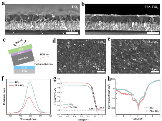
Figure 3.
Physical properties of PSCs with different ETLs. (a,b) Cross-sectional SEM images of perovskite films deposited on different ETLs. (c) Schematic illustration of exposing the buried interface for SEM testing. (d) SEM images for perovskite at the buried interface based on the FTO/TiO2/perovskite films. (e) SEM images for perovskite at the buried interface based on the FTO/PPA-TiO2/perovskite films. (f) PL spectra of the perovskite films deposited on different ETLs. (g) Built-in electric field identified from the Mott–Schottky curves of devices based on different ETLs. (h) Dark J–V curves of the PSCs with TiO2 and PPA-TiO2.
Further, we carried out photoluminescence (PL) measurements to study the electron transport behavior at the interface between the ETL and perovskite. As shown in Figure 3f, the PL spectral intensity of the PPA-TiO2-based perovskite films decreased significantly, which indicates the enhanced electron transport from perovskite to the ETL. Mott–Schottky curves were also created to evaluate the physical properties of PSCs structured as fluorine-doped tin oxide (FTO)/TiO2 or PPA-TiO2/perovskite/methoxy-phenethylammonium iodide (MeO-PEAI)/2,2′,7,7′-tetrakis[N,N-di(4-methoxyphenyl)amino]-9-9′-spirobifluorene (Spiro-OMeTAD)/gold (Au). As shown in Figure 3g, the built-in electric field of the PPA-TiO2-based PSC was 1.06 V stronger than that of the TiO2-based PSC (1.04 V), which should have resulted from the optimized energy level structure of the TiO2 ETL. A stronger built-in electric field is beneficial for photo-generated carrier separation and transport to charge transport layers (ETLs and hole transport layers). In addition, as shown in Figure 3h, the dark J–V curves display that the dark saturation current of PSCs with PPA-TiO2 is smaller than the PSCs with TiO2, which indicates the reduced non-radiative recombination after regulating TiO2 deposition using PPA. This reduced non-radiative recombination should result from the decreased interfacial electron accumulation. The above results exhibit that the PPA-TiO2 can promote interfacial electron transport and reduce carrier non-radiative recombination, which is expected to show a positive effect on the photovoltaic performance of PSCs.
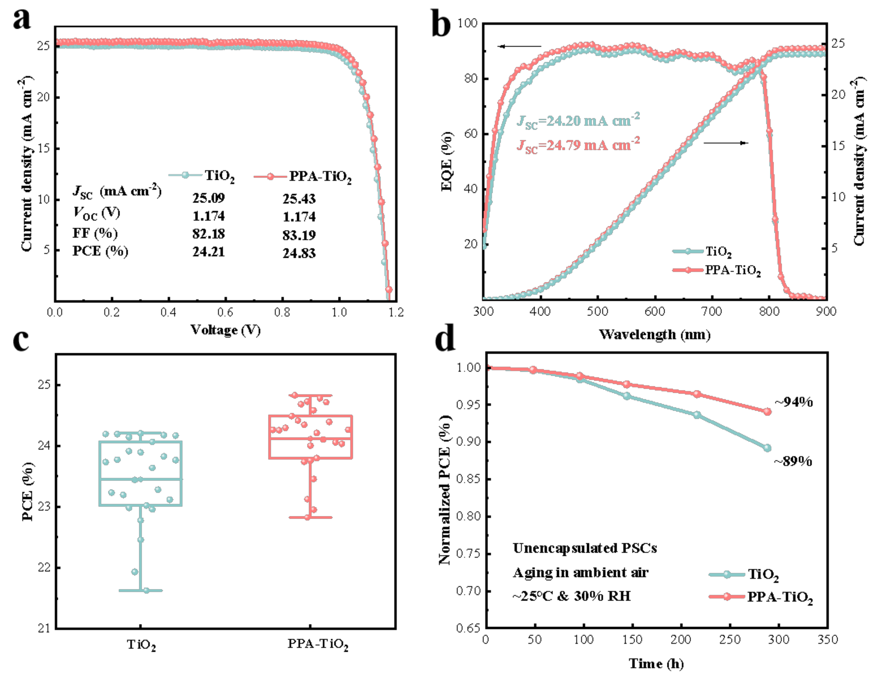
We fabricated planar PSCs structured as FTO/TiO2 (PPA-TiO2)/perovskite/MeO-PEAI/Spiro-OMeTAD/Au and further investigated the differences in photovoltaic performance based on PSCs with different ETLs. Figure 4a illustrates the reverse scan J–V curves of PSCs with champion PCEs based on TiO2 and PPA-TiO2. Impressively, PPA-TiO2 achieved a champion PCE of 24.83% with a short-circuit current density (JSC) of 25.43 mA/cm2, an open-circuit voltage (VOC) of 1.174 V, and a fill factor (FF) of 83.19%. Conversely, the PSCs with TiO2 reached a champion PCE of 24.21%, accompanied by a JSC of 25.38 mA/cm2, a VOC of 1.174 V, and an FF of 82.05%. The corresponding forward scan J–V curves of PSCs with different ETLs are shown in Figure S5. The results show that the VOC and FF of the PSC based on the TiO2 ETL decrease significantly after the reverse scan, but the optimized PSC maintains a high VOC and FF, and the reverse scan PCE is 24.68%. In order to reflect the hysteresis phenomenon of the PSCs more clearly, we calculated the hysteresis index (HI) using the formula of (PCEreverse − PCEforward)/PCEreverse. The value of the HI for the TiO2-based PSC is 3.76%, while the value of the HI for the PPA-TiO2-based PSC is only 0.60%, which is almost negligible. The improvement in the hysteresis phenomenon is related to the charge extraction optimized at the ETL and perovskite interface, which reduces the accumulation of interface charges. The external quantum efficiency (EQE) spectra depicted in Figure 4b show that the integrated JSC values of PSCs with TiO2 and PPA-TiO2 exhibit slight discrepancies compared to those derived from the J–V measurements.
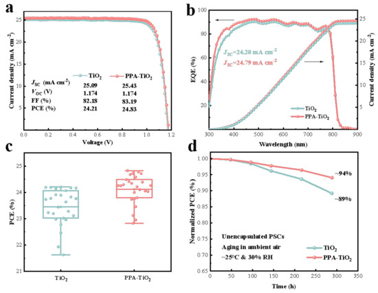
Figure 4.
Photovoltaic performance of PSCs with various ETLs. (a) J–V curves (reverse scans) of the champion PSCs based on the TiO2 and PPA-TiO2 ETL. (b) EQE and integrated current density curves of PSCs based on the TiO2 and PPA-TiO2 ETL. (c) Distribution of the PCE values from 25 devices for each group. (d) PCE evolution of 25 unencapsulated devices stored in ambient conditions (30% RH, 25 °C).
Figure 4c shows the statistical analysis results of the PCE values from 25 devices for each condition, and Figure S6 shows the corresponding statistical distribution of VOC, JSC, and FF. The TiO2-based PSCs possess an average PCE of 23.45%. As a comparison, the PPA-TiO2-based PSCs possess a higher average PCE of 24.11%. The standard deviation (SD) is 0.705 for TiO2-based samples and 0.548 for PPA-TiO2-based samples, which indicates the higher repeatability of PPA-TiO2-based samples than TiO2-based samples. The increased PCE and reproducibility mainly result from the improved and reliable ETL quality after incorporating PPA. A more detailed analysis of the other performance parameters of PSCs shows that the VOC, JSC, and FF are all improved, which is conducive to the improvement of the average PCEs of the PSCs. It is worth noting that the increase in the FF is the most significant, from an average of 79.89% for TiO2-based PSCs to 81.54% for PPA-TiO2-based PSCs, which is related to the improvement of ETL quality and interface contact and defects after PPA optimization. In addition, we also characterized the device’s stability. Long-term storage tests on unencapsulated devices were performed in ambient conditions (30% RH, 25 °C). As shown in Figure 4d, we can observe that the unencapsulated device with PPA-TiO2 retained about 94% of its initial PCE after storage for 288 h, while the device with TiO2 retained about 89% of its initial PCE. Based on these results, it can be seen that PPA-TiO2 can effectively improve the PCEs of PSCs and also have a positive effect on device stability.
3. Conclusions
In this work, we developed high-efficiency PSCs with an FF of more than 83% by regulating TiO2 deposition using PPA. Owing to the modified energy level structure and optimized interfacial contact property resulting from a smooth TiO2 surface, the PSCs with PPA-TiO2 possessed enhanced electron transport. Accordingly, the PSCs with PPA-TiO2 achieved a champion PCE of 24.83%, which was higher than that (24.21%) of PSCs with TiO2. In addition, the PSCs with PPA-TiO2 retained approximately 94% of their initial PCE after storage for 288 h in ambient conditions, showing enhanced storage stability. We believe that this deposition regulation strategy using single-anchored ligands can exhibit wide applicability using various functional materials (Figures S7 and S8 and note S1) and could also be extended to regulate the deposition of other ETLs, which is significant for fabricating high-quality ETLs and directly understanding the influence of ETL modifications on the photovoltaic performance of PSCs, providing a reference for promoting the further development of planar PSCs.
4. Experimental Section
4.1. Materials
The FTO glass substrate (~13 ohm); TiCl4 (Aladdin, Wallingford, CT, USA); Phenylphosphonic acid, Isopropanol, and Acetonitrile (Acros, Waltham, MA, USA); Lead iodide, DMF, DMSO, and Chlorobenzene (Sigma-aldrich, St. Louis, MO, USA); FAI, MACl, CsI, 4-meo-PEAI, Spiro-OMeTAD, Lithiumbis (trifluoromethylsulfonyl) imide; and 4-tertbutylpyri-dine were from Xi’an Polymer Light Technology Corp, Xi’an, China. The deionized water was purified using the UPR-I ultrapure water machine developed by Upupure Technology Co., Ltd, Chengdu, China. We did not purify any chemicals further.
4.2. Device Fabrication
For the preparation of the FTO glass substrates, the FTO glass substrates were placed in custom cleaning boxes soaked in deionized water, ethanol, and deionized water. They were ultrasonically cleaned in an ultrasonic cleaning machine for 20 min each. Plasma cleaning was performed for 20 min after drying the surface moisture with a nitrogen gun, which helped to clean the surface of organic impurities and caused the formation of hydrophilic groups on the surface of the substrates.
4.3. ETL Preparation
A mixture of TiCl4 (4 mL) and deionized water (200 mL) was stirred to obtain a TiO2 precursor. As for the preparation of PAA-TiO2 ETL, phenylphosphonic acid was added to the TiO2 precursor solution at a ratio of 10 milligrams per milliliter of TiCl4. The FTO substrate was placed in a custom CBD container, poured into a pre-prepared precursor to completely soak the substrate, and transferred to a water bath heater set at 70 °C for 40 min to form the ETLs. After the preparation, the ETLs were removed from the chemical bath precursor, and the surface was washed with deionized water, ethanol, and deionized water successively to remove impurities and then dried with N2 for use.
For the preparation of perovskite, the 1.54 M FA0.85MA0.1Cs0.05PbI3 (DMF: DMSO, 4:1 volume/volume) precursor was spin-coated on the FTO/ETLs substrate at 4000 rpm for 18 s and 800 μL ether was dropped after 6 s of rotation. At the end of the spin-coating process, the film was transferred to air (25 °C and 35% RH) and annealed on a hot table at 150 °C for 10 min.
For the preparation of the 4-meo-PEAI layer, 4.5 mg/mL of 4-meo-PEAI dissolved in IPA was spin-coated on a perovskite surface at 4000 rpm for 30 s and annealed on a hot table at 100 °C for 3 min in N2.
For the preparation of the hole transport layer, a Spiro-OMeTAD solution was prepared by mixing 72.3 mg of Spiro-OMeTAD in 1 mL of chlorobenzene with 26.6 μL of TBP and 18 μL of Li-TFSI salt (520 mg mL−1 in ACN), which was spin-coated at 4000 rpm for 30 s in N2.
To obtain the PSCs, an Au electrode (60 nm) was deposited via thermal evaporation. After preparation, the PSCs were transferred to a drying cabinet (25 °C and 15% RH) for oxidation for 12 h.
4.4. Characterization
Cold field-emission scanning electron microscopy (SEM) using a Hitachi S-4800 instrument was used to analyze the surface morphology of the samples. X-ray photoelectron spectroscopy (XPS) and ultraviolet photoelectron spectroscopy (UPS) were performed using an ESCALAB 250Xi system to analyze the surface composition and electronic structure of the samples. Ultraviolet–visible (UV–Vis) spectra were recorded using a SHIMADZU UV-2600 spectrophotometer to study the optical properties of the films. Atomic force microscopy (AFM), Kelvin probe force microscopy (KPFM), and conducting atomic force microscopy (C-AFM) using an FMNanoview 1000 instrument were used to characterize the surface characteristics. Steady-state photoluminescence (PL) was employed to study the carrier behavior of the samples. The excitation wavelength used for these measurements was 470 nm. The Mott–Schottky curves of the solar cells were measured using an electrochemical workstation (Zahner Zennium), the disturbed AC voltage was 50 mV, the frequency was 10 KHz, the step width was 0.01 V, and the bias voltage range was from −0.5 to 1.3 V. The device efficiency was measured using a Keithley 2400 source meter with a scan rate of 13 mV s−1 under simulated AM 1.5G illumination (100 mW cm−2) provided by a 150 W Class AAA solar simulator (XES-40S1, SAN-EI). The external quantum efficiency and integrating current of the perovskite solar cells were measured using QE-R systems (Enli Tech, Shanghai, China) under AC pattern conditions.
Supplementary Materials
The following supporting information can be downloaded at: https://www.mdpi.com/article/10.3390/ma17153820/s1, Figure S1: The molecular structure formula of phenylphosphonic acid; Figure S2: Optical transmittance spectra of ETLs; Figure S3: Tauc plots of ETLs; Figure S4: UPS profiles of ETLs; Figure S5: Forward scan J–V curves of PSCs with different ETLs; Figure S6: Distribution of the photovoltaic parameters for PSCs based on different ETLs; Figure S7: The molecular formula of the β-Guanidinopropionic acid; Figure S8: Surface SEM images of ETLs, respectively.
Author Contributions
Z.X., Z.L. (Zhineng Lan) and J.J. conceived the idea of the article. J.J. guided the work as a supervisor. Z.L. (Zhineng Lan) and L.W. designed the experiments, and AFM, KPFM, and C-AFM conducted the tests. L.Y. participated in the PSC fabrication and characterization. F.C. assisted with the AFM, KPFM, and C-AFM tests and data analysis. C.Y. contributed to the SEM, UPS, and XPS characterization. L.W. and Z.L. (Zhehan Li) wrote the first draft of the manuscript. Z.L. (Zhineng Lan) and L.Y. assisted in revising and polishing the manuscript’s language. All authors have read and agreed to the published version of the manuscript.
Funding
This work is partially supported by the KY2022-JD-02-12 project.
Institutional Review Board Statement
Not applicable.
Informed Consent Statement
Not applicable.
Data Availability Statement
The original contributions presented in the study are included in the article/Supplementary Materials, further inquiries can be directed to the corresponding author.
Acknowledgments
We thank Y.Y.M (Institute of Quality Standard and Testing Technology for Agro-products of Caas) for helping us characterize the microstructure of the sample using scanning electron microscopy. We also thank C. Guo (Tsinghua University Analysis Center) for helping us to use Fourier infrared spectroscopy to characterize the molecular structure and chemical composition of the sample. We also thank J.Y. Wang (Technical Institute of Physics and Chemistry, CAS) for helping us to use UPS and XPS to characterize the elemental composition, chemical properties, and energy levels of the samples.
Conflicts of Interest
Authors Zhanpeng Xu, Fuxin Chen, and Chong Yin were employed by the company Power China Huadong Engineering Corporation Limited, Hangzhou 311122, China. The remaining authors declare that the research was conducted in the absence of any commercial or financial relationships that could be construed as a potential conflict of interest.
References
- Čulík, P.; Brooks, K.; Momblona, C.; Adams, M.; Kinge, S.; Maréchal, F.; Nazeeruddin, M.K. Design and cost analysis of 100 MW perovskite solar panel manufacturing process in different locations. ACS Energy Lett. 2022, 7, 3039–3044. [Google Scholar] [CrossRef]
- Yan, L.; Huang, H.; Cui, P.; Du, S.; Lan, Z.; Yang, Y.; Li, M. Fabrication of perovskite solar cells in ambient air by blocking perovskite hydration with guanabenz acetate salt. Nat. Energy 2023, 8, 1158–1167. [Google Scholar] [CrossRef]
- Kojima, A.; Teshima, K.; Shirai, Y.; Miyasaka, T. Organometal halide perovskites as visible-light sensitizers for photovoltaic cells. J. Am. Chem. Soc. 2009, 131, 6050–6051. [Google Scholar] [CrossRef] [PubMed]
- Best Research-Cell Efficiency Chart. Available online: https://www.nrel.gov/pv/cell-efficiency.html (accessed on 8 May 2024).
- Kim, J.Y.; Lee, J.W.; Jung, H.S.; Shin, H.; Park, N.G. High-efficiency perovskite solar cells. Chem. Rev. 2020, 120, 7867–7918. [Google Scholar] [CrossRef] [PubMed]
- Lee, J.; Son, T.; Min, K.; Park, S.; Kim, Y.; Seo, J. Rationally designed hole transporting layer system for efficient and stable perovskite solar cells. EcoMat 2023, 5, e12414. [Google Scholar] [CrossRef]
- Zhang, T.; He, Q.; Yu, J.; Chen, A.; Zhang, Z.; Pan, J. Recent progress in improving strategies of inorganic electron transport layers for perovskite solar cells. Nano Energy 2022, 104, 107918. [Google Scholar] [CrossRef]
- Wang, Y.; Wan, J.; Ding, J.; Hu, J.S.; Wang, D. A rutile TiO2 electron transport layer for the enhancement of charge collection for efficient perovskite solar cells. Angew. Chem. Int. Ed. 2019, 58, 9414–9418. [Google Scholar] [CrossRef]
- Tan, H.; Jain, A.; Voznyy, O.; Lan, X.; García de Arquer, F.P.; Fan, J.Z.; Sargent, E.H. Efficient and stable solution-processed planar perovskite solar cells via contact passivation. Science 2017, 355, 722–726. [Google Scholar] [CrossRef]
- Chen, H.; Liu, T.; Zhou, P.; Li, S.; Ren, J.; He, H.; Guo, S. Efficient bifacial passivation with crosslinked thioctic acid for high-performance methylammonium lead iodide perovskite solar cells. Adv. Mater. 2020, 32, 1905661. [Google Scholar] [CrossRef] [PubMed]
- Wang, B.; Zhang, M.; Cui, X.; Wang, Z.; Rager, M.; Yang, Y.; Lin, Z. Unconventional route to oxygen-vacancy-enabled highly efficient electron extraction and transport in perovskite solar cells. Angew. Chem. Int. Ed. 2020, 59, 1611–1618. [Google Scholar] [CrossRef] [PubMed]
- Jang, S.; Yoon, J.; Ha, K.; Kim, M.C.; Kim, D.H.; Kim, S.M.; Choi, M. Facile fabrication of three-dimensional TiO2 structures for highly efficient perovskite solar cells. Nano Energy 2016, 22, 499–506. [Google Scholar] [CrossRef]
- Zhen, C.; Wu, T.; Chen, R.; Wang, L.; Liu, G.; Cheng, H.M. Strategies for modifying TiO2 based electron transport layers to boost perovskite solar cells. ACS Sustain. Chem. Eng. 2019, 7, 4586–4618. [Google Scholar] [CrossRef]
- Rajbhandari, P.P.; Dhakal, T.P. Low temperature ALD growth optimization of ZnO, TiO2, and Al2O3 to be used as a buffer layer in perovskite solar cells. J. Vac. Sci. Technol. A 2020, 38, 032406. [Google Scholar] [CrossRef]
- Chen, C.; Cheng, Y.; Dai, Q.; Song, H. Radio frequency magnetron sputtering deposition of TiO2 thin films and their perovskite solar cell applications. Sci. Rep. 2015, 5, 17684. [Google Scholar] [CrossRef] [PubMed]
- Huang, H.; Cui, P.; Chen, Y.; Yan, L.; Yue, X.; Qu, S.; Li, M. 24.8%-efficient planar perovskite solar cells via ligand-engineered TiO2 deposition. Joule 2022, 6, 2186–2202. [Google Scholar] [CrossRef]
- Kim, M.; Jeong, J.; Lu, H.; Lee, T.K.; Eickemeyer, F.T.; Liu, Y.; Kim, D.S. Conformal quantum dot–SnO2 layers as electron transporters for efficient perovskite solar cells. Science 2022, 375, 302–306. [Google Scholar] [CrossRef] [PubMed]
- Liang, C.; Wu, Z.; Li, P.; Fan, J.; Zhang, Y.; Shao, G. Chemical bath deposited rutile TiO2 compact layer toward efficient planar heterojunction perovskite solar cells. Appl. Surf. Sci. 2017, 391, 337–344. [Google Scholar] [CrossRef]
- Cui, P.; Wei, D.; Ji, J.; Huang, H.; Jia, E.; Dou, S.; Li, M. Planar p–n homojunction perovskite solar cells with efficiency exceeding 21.3%. Nat. Energy 2019, 4, 150–159. [Google Scholar] [CrossRef]
- Li, Y.; Chen, Z.; Yu, B.; Tan, S.; Cui, Y.; Wu, H.; Meng, Q. Efficient, stable formamidinium-cesium perovskite solar cells and minimodules enabled by crystallization regulation. Joule 2022, 6, 676–689. [Google Scholar] [CrossRef]
- Wang, W.; Lin, Y.; Zhang, G.; Kang, C.; Pan, Z.; Zhong, X.; Rao, H. Modification of compact TiO2 layer by TiCl4-TiCl3 mixture treatment and construction of high-efficiency carbon-based CsPbI2Br perovskite solar cells. J. Energy Chem. 2021, 63, 442–451. [Google Scholar] [CrossRef]
- Haruyama, J.; Sodeyama, K.; Hamada, I.; Han, L.; Tateyama, Y. First-principles study of electron injection and defects at the TiO2/CH3NH3PbI3 interface of perovskite solar cells. J. Phys. Chem. Lett. 2017, 8, 5840–5847. [Google Scholar] [CrossRef] [PubMed]
- Wang, X.; Huang, H.; Wang, M.; Lan, Z.; Cui, P.; Du, S.; Li, M. Oriented molecular bridge constructs homogeneous buried interface for perovskite solar cells with efficiency over 25.3%. Adv. Mater. 2024, 36, 2310710. [Google Scholar] [CrossRef] [PubMed]
- Yue, X.; Fan, B.; Zhao, X.; Yang, Y.; Qu, S.; Zhang, Q.; Li, M. Energy level modulation of TiO2 using amino trimethylene phosphonic acid for efficient perovskite solar cells with an average VOC of 1.19 V. Sustain. Energy Fuels 2023, 7, 727. [Google Scholar] [CrossRef]
- Yang, Y.; Huang, H.; Yan, L.; Cui, P.; Lan, Z.; Sun, C.; Li, M. Compatible soft-templated deposition and surface molecular bridge construction of SnO2 enable air-fabricated perovskite solar cells with efficiency exceeding 25.7%. Adv. Energy Mater. 2024, 14, 2400416. [Google Scholar] [CrossRef]

Disclaimer/Publisher’s Note: The statements, opinions and data contained in all publications are solely those of the individual author(s) and contributor(s) and not of MDPI and/or the editor(s). MDPI and/or the editor(s) disclaim responsibility for any injury to people or property resulting from any ideas, methods, instructions or products referred to in the content. |
© 2024 by the authors. Licensee MDPI, Basel, Switzerland. This article is an open access article distributed under the terms and conditions of the Creative Commons Attribution (CC BY) license (https://creativecommons.org/licenses/by/4.0/).