Advances in Nickel-Containing High-Entropy Alloys: From Fundamentals to Additive Manufacturing

 , , ,
, , ,  , , , , and
Abstract
:1. Introduction
2. High Entropy Alloys (HEAs)
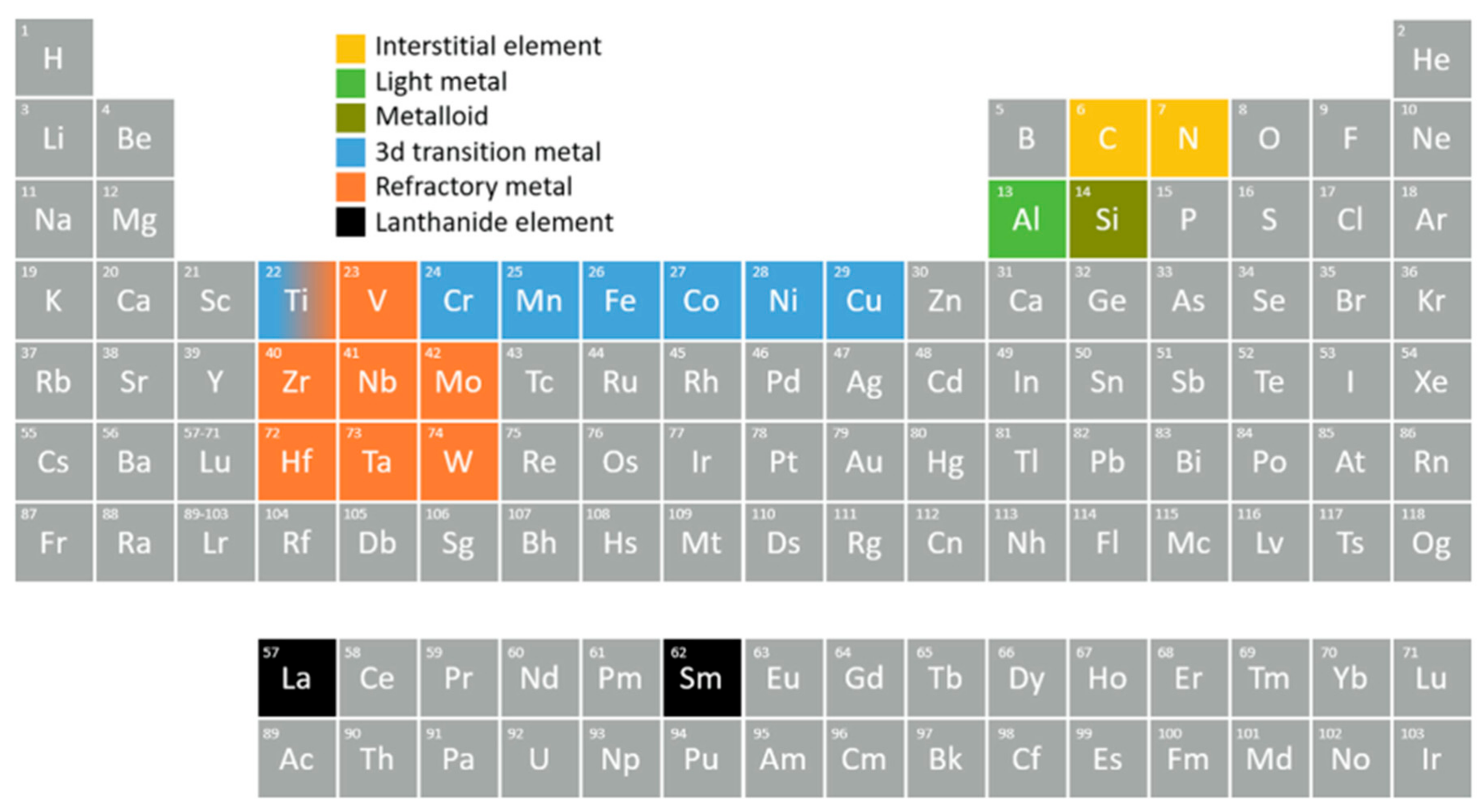
3. Selection of Elements for HEA
4. Mechanical Properties and Defects of HEAs Processed by Additive Manufacturing
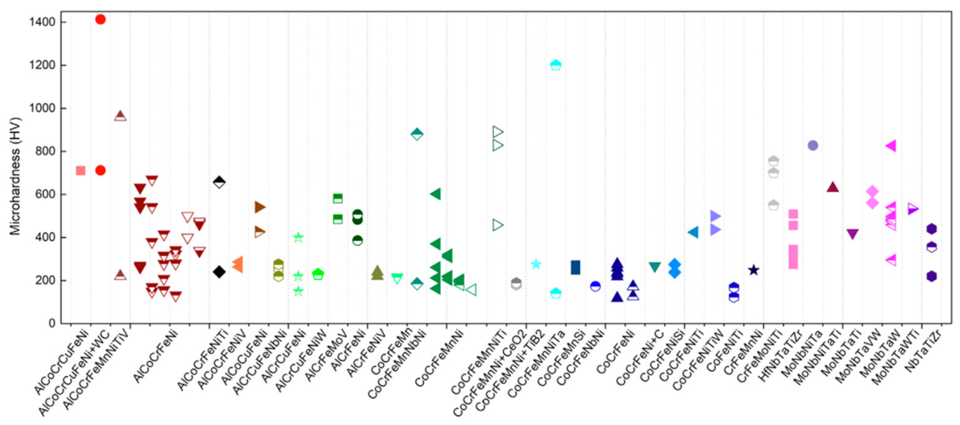
4.1. Microhardness
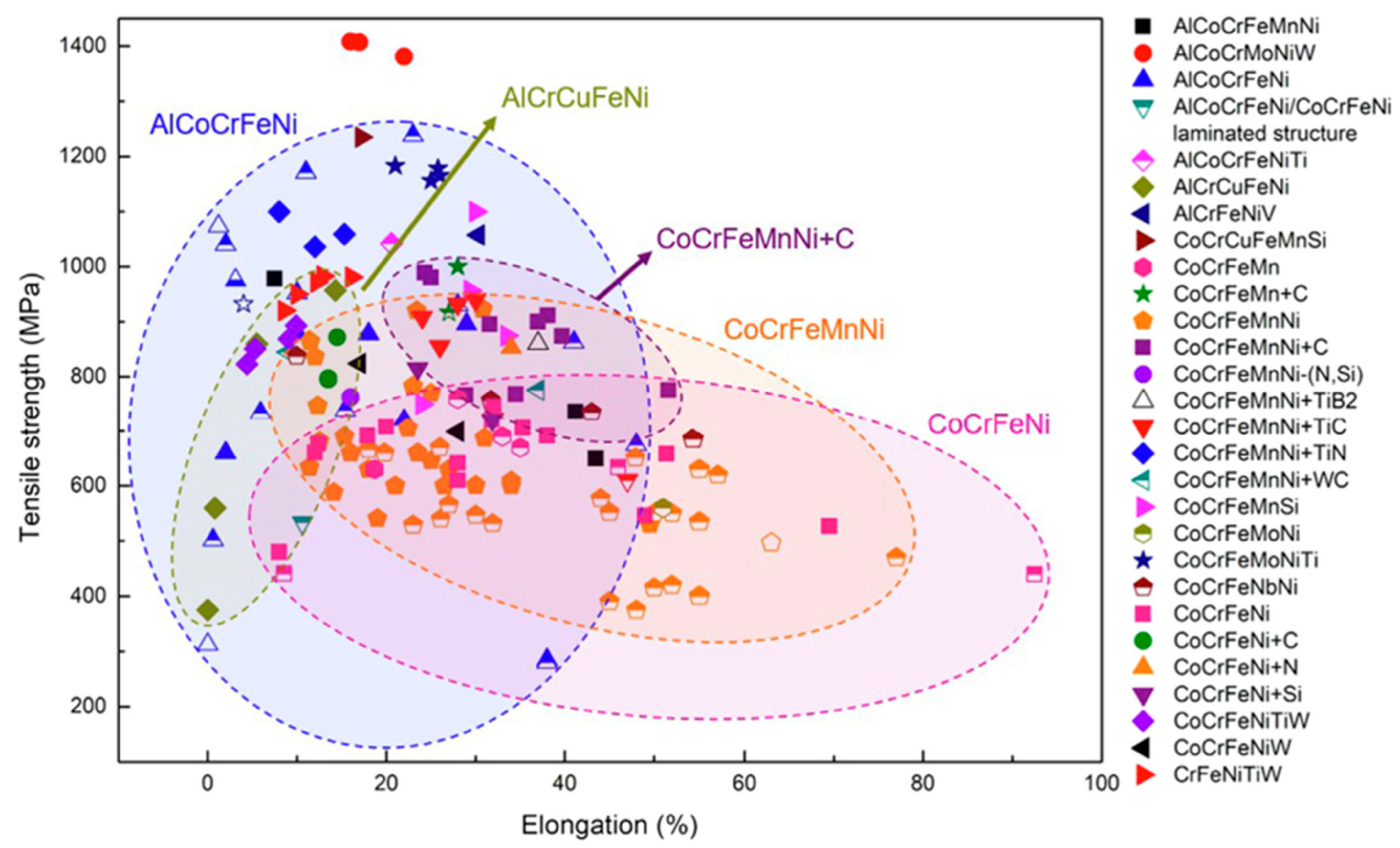
4.2. Tensile Properties

| HEAs System | AM Techniques | Powder Size (μm) | Density | Relative Density | Printing Parameters | Phase Compositions | Yield Stength (MPa) | Ultimate Tensile Strength (MPa) | Elongation (%) | Hardness (HV) | Ref. |
|---|---|---|---|---|---|---|---|---|---|---|---|
| Al0.3CoCrFeNi | SLM | 20–42 | 7.76 | 99.9 | P = 150–170 W, v = 1100–1300 mm s−1, t = 25–30 µm, h = 45 µm | FCC | ~730 | 896 | 29 | - | [70] |
| Al0.5CoCrFeNi | SLM | 15–45 | - | - | P = 400 W, v = 270 mm s−1, t = 40 µm, h = 90 µm | FCC | 579 | 721 | 22 | 262.5 ± 5 | [71] |
| AlCoCrFeNi | EBM | 45–105 | - | - | - | FCC + BCC | - | - | - | - | [72] |
| Al0.1CoCrFeNi | SLM | 20–63 | - | - | P = 150 W, v = 1600 mm s−1, t = 50 µm, h = 100 µm | FCC | - | 520 | ~2 | - | [73] |
| Al0.5CoCrFeNi | SLM | 37–74 | - | 99.92 | P = 320 W, v = 800 mm s−1, t = 60 µm, h = 50 µm | FCC + BCC | 609 | 878 | ~0.175 | 270 | [74] |
| AlCoCrFeNi | SLM | 27–65 | - | - | P = 120 W, t = 50–80 µm, h = 25 µm | BCC | - | - | - | 541 ± 18 | [75] |
| AlCoCrFeNi | SLM | - | - | - | P = 98 W, v = 2000 mm s−1, t = 52 µm | BCC + B2 | - | - | - | - | [76] |
| AlCoCrFeNi | EBM | ~70 | - | - | Voltage = 60 kV, vacuum = 7 × 10⁻¹ Pa of He, build plate temperature = 1173 K | FCC + BCC + B2 | 769 ± 12.7 | 1073.5 ± 21.3 | 1.2 ± 0.2 | - | [77,78] |
| AlCoCrFeNiTi | SLM | 22–65 | - | - | P = 260 W, v = 1000 mm s−1, t = 50 µm, h = 70 µm | FCC + Oxides | 1235 | 1550 | 10.69 | - | [78] |
| Al4(CoCrFeNi)94Ti2 | SLM | 22–65 | - | - | P = 400 W, v = 10 mm s−1, h = 460 µm | FCC | - | - | - | - | [79] |
| Al0.5Cr0.8CoFeNi2.5V0.2 | SLM | 15–75 | - | ~98.9 | P = 250 W, v = 960 mm s−1, t = 40 µm, h = 80 µm | FCC | 530 ± 15 | 1842 ± 35 | 40 | 263 ± 10 | [80] |
| AlCrFeNiV | SLM | 20–80 | - | 99.88 | P = 140 W, v = 900 mm s−1, t = ~30 µm, h = 50 µm | FCC | 651.36 | ~1057.47 | 30.3 | - | [81] |
| FeCoCrNi | SLM | - | - | - | P = 200 W, v = 300 mm s−1, t = 20 µm | FCC | 600 | 745 | 32 | 238 | [65] |
| - | - | - | P = 200 W, v = 300 mm s−1, t = 50 µm | FCC | 402 | 480 | 8 | 205 | [65] | ||
| 14–48 | - | 99.71 ± 0.25 | P = 200 W, v = 740 mm s−1, t = 40 µm, h = 40 µm | FCC | 581.9 | 707.9 | 20 | 218 | [82] | ||
| 14–48 | - | 99.71 ± 0.25 | Annealed at 1573 K for 2 h | FCC | 221 | 633.2 | 45 | 138 | [82] | ||
| FeCoNiCuAl | SLM | 15–65 | - | ~96 | P = 100–400 W, v = 400–1200 mm s−1, t = 40 µm, h = 80 µm | BCC matrix + Cu-rich B2 | - | - | - | ~858 | [83] |
| Ni6Cr4WFe9Ti | SLM | 15–53 | - | - | P = 300 W, v = 2500 mm s−1, t = 100 µm, h = 80 µm | - | 742 | 972 | 12.2 | - | [84] |
| CoCrFeNiMn | EBM | 45–106 | - | - | Reference current = 2–14, scanning speed = 492–3446 mm/s), layer thickness = 50–70 µm, hatch depth = 50–70 µm | - | 205 ± 3 | 497 ± 2 | 63 ± 1 | 157.1 | [85] |
| CoCrFeNiW0.2 | SLM | 15–45 | - | - | P = 175 W, v = 150 mm s−1, t = 30 µm, h = 100 µm | FCC + W | 610 ± 15 | 814 ± 9 | 17 ± 1 | 314.1 | [86] |
| CoCrFeMnNi | SLM | 5–45 | - | - | P = 400 W, v = 830 mm s−1, t = 30 µm, h = 90 µm | FCC | - | 601 | 35 | - | [87] |
| SLM | - | - | - | P = 400 W, v = 830 mm s−1, t = 30 µm, h = 90 µm then HIP temp 1150 °C, time 3 h, and pressure 150 MPa | FCC | - | 649 | 18 | - | [87] | |
| SLM | - | - | 99.2 | P = 240 W, v = 2000 mm s−1, t = 40 µm, h = 50 µm | FCC | 510 ± 10 | 609 ± 10 | 34 ± 3 | - | [88] | |
| SLM | 5–45 | - | 99.2 | P = 240 W, v = 2000 mm s−1, t = 40 µm, h = 50 µm then HT at 900 °C for 1 h in Ar atmosphere | FCC | 381 ± 8 | 619 ± 5 | 47 ± 2 | - | [88] | |
| CrFeNiMn | SLM | 20–45 | - | 98.0% ± 0.1 | P = 70 W, v = 200 mm s−1, t = 25 µm, h = 90 µm | FCC | - | - | - | 248 ± 8 | [89] |
| NbMoTaW | SLM | - | - | - | P = 400 W, v = 250 mm s−1, t = 100 µm, h = 100 µm | - | - | - | - | 826 | [90] |
| Ni6Cr4WFe9T | SLM | 15–53 | - | - | P = 300 W, v = 2500 mm s−1, t = 100 µm, h = 80 µm | - | 742 | 972 | 12.2 | - | [84] |
| HEAs System | AM Techniques | Powder Size (μm) | Density | Relative Density | Printing Parameters | Phase Compositions | Yield Compressive Stength (Mpa) | Compressive Fracture Stength (Mpa) | Elongation (%) | Hardness (HV) | Ref. |
|---|---|---|---|---|---|---|---|---|---|---|---|
| AlCoCrFeNi | EBM | ~70 | - | - | Voltage = 60 kV, print orientation 0 degrees | FCC + BCC | 1015.0 ± 52.5 | 1668.3 ± 71.5 | 26.4 ± 6.7 | - | [91] |
| AlCoCrFeNi | EBM | ~70 | - | - | Voltage = 60 kV, print orientation 90 degrees | FCC + BCC | 944.0 ± 55.4 | 1447.0 ± 135.8 | 14.5 ± 5.3 | - | [91] |
| Al2.1Co0.3Cr0.5FeNi2.1 | WAAM | - | - | - | Wire feed speed 8 m/min, voltage 17 V, travel speed 0.3 m/min, substrate heating temperature ≈ 250 °C | A2 + B2 | 550 | 1899 | 18.5 | 463 | [92] |
| AlCoCrFeNi | BJ | ~32 | - | - | 50 μm layer thickness, recoating speed of 1 mm/s, binder saturation 60%, heating power of 50%, and a drying time of 25 s, sintering at 1320 °C for 4 h, annealing at 1000 °C | FCC + BCC + B2 | 1203 ± 22 | 1996 ± 45 | 32.25 ± 2.5 | 418.1 | [93] |
| AlCoCrFeNi | BJ | ~32 | - | - | 50 μm layer thickness, recoating speed of 1 mm/s, binder saturation 60%, heating power of 50%, and a drying time of 25 s, sintering at 1320 °C for 4 h, annealing at 1200 °C | FCC + BCC + B2 | 1461 ± 23 | 2272 ± 48 | 31.46 ± 2.1 | 499.6 | [93] |
| AlCrCuFeNi | SLM | 11–58 | - | - | P = 300 W, v = 600 mm s−1, t = 40 µm, h = 80 µm | BCC | - | 2052.8 ± 123.6 | 6.8 ± 1.3 | - | [94] |
| AlCrCuFeNiW1 | LMD | 90–150 | - | - | P = 1600 W, v = 20 mm s−1, t = 40 µm | FCC + BCC | 998.4 | 1274.6 | 24.3 | 240 ± 10 | [95] |
| AlCrCuFeNiW3 | LMD | 90–150 | - | - | P = 1600 W, v = 20 mm s−1, t = 40 µm | FCC + BCC | 1005.9 | 1287.9 | 23.4 | 230 ± 10 | [95] |
| CoCrFeMnNi | SLM | 18–38 | - | - | P = 90 W, v = 600 mm s−1, t =25 µm, h = 80 µm in scanning direction | FCC | 778.4 | - | - | - | [70] |
| CoCrFeMnNi | SLM | 18–38 | - | - | P = 90 W, v = 600 mm s−1, t = 25 µm, h = 80 µm in transverse direction | FCC | 766.4 | - | - | - | [70] |
| CoCrFeMnNi | SLM | 18–38 | - | - | P = 90 W, v = 600 mm s−1, t = 25 µm, h = 80 µm in building direction | FCC | 703.5 | - | - | - | [70] |
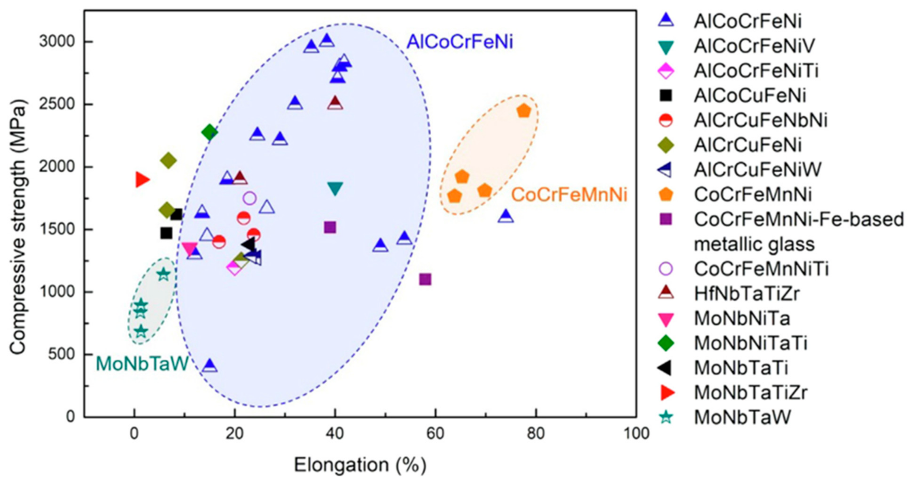
4.3. Compressive Properties
4.4. Porosity
5. Effect of VEC on Ni-Based HEAs
6. Pressure-Induced FCC to HCP Phase Transition in Ni-Based HEAs
7. Precipitation-Strengthened Ni-Based HEAs
8. Substitute for TRIP and TWIP Steels via Ni-Based HEAs
9. Thermal Shock and Oxidation Resistance on Ni-Containing HEA
10. Concluding Remarks
Author Contributions
Funding
Institutional Review Board Statement
Informed Consent Statement
Data Availability Statement
Acknowledgments
Conflicts of Interest
References
- Sharma, P. A Brief Account of Man, Material and Manufacturing: On the Timeline. Mater. Today Proc. 2022, 66, 3572–3577. [Google Scholar] [CrossRef]
- ASM International. Properties and Selection: Irons, Steels, and High-Performance Alloys; ASM International: Materials Park, OH, USA, 1990; ISBN 978-1-62708-161-0. [Google Scholar]
- Chikumba, S.; Rao, V.V. High Entropy Alloys: Development and Applications. In Proceedings of the 7th International Conference on Latest Trends in Engineering & Technology (ICLTET 2015), Pretoria, South Africa, 25–27 November 2015; pp. 1–5. [Google Scholar]
- Sharma, P.; Naushin, N.; Rohila, S.; Tiwari, A. Magnesium Containing High Entropy Alloys. In Magnesium Alloys Structure and Properties; IntechOpen: Rijeka, Croatia, 2022. [Google Scholar]
- Gupta, A.K.; Mallik, B.; Roy, D. Structure Property Correlation of In Situ Reinforced Al–Based Metal Matrix Composite via Stir Casting. Mater. Perform. Charact. 2020, 9, 20190038. [Google Scholar] [CrossRef]
- Roy, D.; Gupta, A.K.; Alam, S.; Srikanth, S.; Jha, B.K. Enhancement of Properties of Micro-Alloyed Low-Carbon Ni-Added Steel by Thermomechanical Treatment. J. Mater. Eng. Perform. 2020, 29, 7952–7963. [Google Scholar] [CrossRef]
- Kang, B.; Lee, J.; Ryu, H.J.; Hong, S.H. Ultra-High Strength WNbMoTaV High-Entropy Alloys with Fine Grain Structure Fabricated by Powder Metallurgical Process. Mater. Sci. Eng. A 2018, 712, 616–624. [Google Scholar] [CrossRef]
- Roy, A.; Hussain, A.; Sharma, P.; Balasubramanian, G.; Taufique, M.F.N.; Devanathan, R.; Singh, P.; Johnson, D.D. Rapid Discovery of High Hardness Multi-Principal-Element Alloys Using a Generative Adversarial Network Model. Acta Mater. 2023, 257, 119177. [Google Scholar] [CrossRef]
- Sharma, P.; Das, C.; Sreeramagiri, P.; Balasubramanian, G. Additively Manufactured Lightweight and Hard High-Entropy Alloys by Thermally Activated Solvent Extraction. High Entropy Alloys Mater. 2024, 2, 41–47. [Google Scholar] [CrossRef]
- Sharma, P.; Singh, P.; Balasubramanian, G. Engineering Phonon Transport through Cation Disorder in Dimensionally Constricted High Entropy MXene. Carbon 2024, 223, 119015. [Google Scholar] [CrossRef]
- Sharma, P.; Balasubramanian, G. Electronic and Lattice Distortions Induce Elastic Softening in Refractory Multicomponent Borides. Chem. Mater. 2023, 35, 7511–7520. [Google Scholar] [CrossRef] [PubMed]
- Singh, P.; Acemi, C.; Kuchibhotla, A.; Vela, B.; Sharma, P.; Zhang, W.; Mason, P.; Balasubramanian, G.; Karaman, I.; Arroyave, R.; et al. Alloying Effects on the Transport Properties of Refractory High-Entropy Alloys. Acta Mater. 2024, 276, 120032. [Google Scholar] [CrossRef]
- Singh, P.; Vela, B.; Ouyang, G.; Argibay, N.; Cui, J.; Arroyave, R.; Johnson, D.D. A Ductility Metric for Refractory-Based Multi-Principal-Element Alloys. Acta Mater. 2023, 257, 119104. [Google Scholar] [CrossRef]
- Singh, P.; Sharma, A.; Smirnov, A.V.; Diallo, M.S.; Ray, P.K.; Balasubramanian, G.; Johnson, D.D. Design of High-Strength Refractory Complex Solid-Solution Alloys. NPJ Comput. Mater. 2018, 4, 16. [Google Scholar] [CrossRef]
- Singh, P.; Trehern, W.; Vela, B.; Sharma, P.; Kirk, T.; Pei, Z.; Arroyave, R.; Gao, M.C.; Johnson, D.D. Understanding the Effect of Refractory Metal Chemistry on the Stacking Fault Energy and Mechanical Property of Cantor-Based Multi-Principal Element Alloys. Int. J. Plast. 2024, 179, 104020. [Google Scholar] [CrossRef]
- Sharma, P. Synthesis of Superhard Multi-Principal Element Alloy Coatings by Spark Hardening. 2021. Available online: https://www.researchgate.net/publication/378182272_Synthesis_of_Superhard_Multi-Principal_Element_Alloy_Coatings_by_Spark_Hardening (accessed on 18 July 2024).
- Yeh, J.-W.; Chen, S.-K.; Lin, S.-J.; Gan, J.-Y.; Chin, T.-S.; Shun, T.-T.; Tsau, C.-H.; Chang, S.-Y. Nanostructured High-Entropy Alloys with Multiple Principal Elements: Novel Alloy Design Concepts and Outcomes. Adv. Eng. Mater. 2004, 6, 299–303. [Google Scholar] [CrossRef]
- Cantor, B.; Chang, I.T.H.; Knight, P.; Vincent, A.J.B. Microstructural Development in Equiatomic Multicomponent Alloys. Mater. Sci. Eng. A 2004, 375–377, 213–218. [Google Scholar] [CrossRef]
- Roy, D.; Pal, S.; Tiwary, C.S.; Gupta, A.K.; Babu, P.N.; Mitra, R. Stable Nanocrystalline Structure Attainment and Strength Enhancement of Cu Base Alloy Using Bi-Modal Distributed Tungsten Dispersoids. Philos. Mag. 2022, 102, 189–209. [Google Scholar] [CrossRef]
- Chakraborty, S.; Gupta, A.K.; Roy, D.; Basumallick, A. Studies on nano-metal dispersed Cu-Cr matrix composite. Mater. Lett. 2019, 257, 126739. [Google Scholar] [CrossRef]
- Roy, D.; Chakraborty, S.; Gupta, A.; Mallick, A.B.; Koch, C.C. Synergistic Effect of Nb and Zr Addition in Thermal Stabilization of Nano-Crystalline Cu Synthesized by Ball Milling. Mater. Lett. 2020, 271, 127780. [Google Scholar] [CrossRef]
- Roy, D.; Chakraborty, S.; Gupta, A.K.; BasuMallick, A.; Scattergood, R.O.; Koch, C.C. Synergistic Effect of Nb and Zr Additions on the Structure-Property Relationships of Nanocrystalline Cu Processed by Mechanical Alloying and Hot Pressing. J. Alloys Compd. 2021, 854, 157174. [Google Scholar] [CrossRef]
- Chakraborty, S.; Gupta, A.K.; Roy, D.; Mallick, A.B. Nanomechanical Properties of Mechanically Alloyed and Spark Plasma Sintered W-Nanoparticulate Dispersed Cu-Nb Alloys. Mater. Lett. 2020, 274, 128004. [Google Scholar] [CrossRef]
- Sharma, P.; Gandhi, P.M.; Chintersingh, K.-L.; Schoenitz, M.; Dreizin, E.L.; Liou, S.-C.; Balasubramanian, G. Accelerated Intermetallic Phase Amorphization in a Mg-Based High-Entropy Alloy Powder. J. Magnes. Alloys 2024, 12, 1792–1798. [Google Scholar] [CrossRef]
- Koch, C.C.; Youssef, K.M.; Scattergood, R.O.; Murty, K.L. Breakthroughs in Optimization of Mechanical Properties of Nanostructured Metals and Alloys. Adv. Eng. Mater. 2005, 7, 787–794. [Google Scholar] [CrossRef]
- Weissmüller, J.; Löffler, J.; Kleber, M. Atomic Structure of Nanocrystalline Metals Studied by Diffraction Techniques and EXAFS. Nanostruct. Mater. 1995, 6, 105–114. [Google Scholar] [CrossRef]
- Günther, B.; Kumpmann, A.; Kunze, H.-D. Secondary Recrystallization Effects in Nanostructured Elemental Metals. Scr. Metall. Et. Mater. 1992, 27, 833–838. [Google Scholar] [CrossRef]
- Olevsky, E.A.; Bradbury, W.L.; Haines, C.D.; Martin, D.G.; Kapoor, D. Fundamental Aspects of Spark Plasma Sintering: I. Experimental Analysis of Scalability. J. Am. Ceram. Soc. 2012, 95, 2406–2413. [Google Scholar] [CrossRef]
- Achard, F.C. Recherches sur les Propriétés des Alliages Métalliques; Imprimé Chez George Jacques Decker & Fils: Berlin, Germany, 1982. [Google Scholar]
- Senkov, O.N.; Wilks, G.B.; Miracle, D.B.; Chuang, C.P.; Liaw, P.K. Refractory high-entropy alloys. Intermetallics 2010, 18, 1758–1765. [Google Scholar] [CrossRef]
- Wu, Z.; Bei, H.; Otto, F.; Pharr, G.M.; George, E.P. Recovery, Recrystallization, Grain Growth and Phase Stability of a Family of FCC-Structured Multi-Component Equiatomic Solid Solution Alloys. Intermetallics 2014, 46, 131–140. [Google Scholar] [CrossRef]
- Gao, M.C.; Zhang, B.; Guo, S.M.; Qiao, J.W.; Hawk, J.A. High-Entropy Alloys in Hexagonal Close-Packed Structure. Metall. Mater. Trans. A 2016, 47, 3322–3332. [Google Scholar] [CrossRef]
- Zhao, Y.J.; Qiao, J.W.; Ma, S.G.; Gao, M.C.; Yang, H.J.; Chen, M.W.; Zhang, Y. A Hexagonal Close-Packed High-Entropy Alloy: The Effect of Entropy. Mater. Des. 2016, 96, 10–15. [Google Scholar] [CrossRef]
- Gludovatz, B.; Hohenwarter, A.; Thurston, K.V.S.; Bei, H.; Wu, Z.; George, E.P.; Ritchie, R.O. Exceptional Damage-Tolerance of a Medium-Entropy Alloy CrCoNi at Cryogenic Temperatures. Nat. Commun. 2016, 7, 10602. [Google Scholar] [CrossRef]
- Hemphill, M.A.; Yuan, T.; Wang, G.Y.; Yeh, J.W.; Tsai, C.W.; Chuang, A.; Liaw, P.K. Fatigue behavior of Al0.5CoCrCuFeNi high entropy alloys. Acta Mater. 2012, 60, 5723–5734. [Google Scholar] [CrossRef]
- Senkov, O.N.; Senkova, S.V.; Dimiduk, D.M.; Woodward, C.; Miracle, D.B. Oxidation Behavior of a Refractory NbCrMo0.5Ta0.5TiZr Alloy. J. Mater. Sci. 2012, 47, 6522–6534. [Google Scholar] [CrossRef]
- Kao, Y.-F.; Chen, S.-K.; Chen, T.-J.; Chu, P.-C.; Yeh, J.-W.; Lin, S.-J. Electrical, Magnetic, and Hall Properties of AlxCoCrFeNi High-Entropy Alloys. J. Alloys Compd. 2011, 509, 1607–1614. [Google Scholar] [CrossRef]
- Liaw, P.K.; Egami, T.; Zhang, C.; Zhang, F.; Zhang, Y. Radiation Behavior of High-Entropy Alloys for Advanced Reactors; Final Report; U.S. Department of Energy: Idaho Falls, ID, USA, 2015. [Google Scholar]
- Lu, C.; Niu, L.; Chen, N.; Jin, K.; Yang, T.; Xiu, P.; Zhang, Y.; Gao, F.; Bei, H.; Shi, S.; et al. Enhancing Radiation Tolerance by Controlling Defect Mobility and Migration Pathways in Multicomponent Single-Phase Alloys. Nat. Commun. 2016, 7, 13564. [Google Scholar] [CrossRef]
- Zhao, Z.K.; Li, J.C.; Jiang, Q. Hypereutectic Al-Si Binary Alloys Prepared by Melt Spinning Method. Adv. Eng. Mater. 2004, 6, 303–306. [Google Scholar] [CrossRef]
- Senkov, O.N.; Miller, J.D.; Miracle, D.B.; Woodward, C. Accelerated Exploration of Multi-Principal Element Alloys with Solid Solution Phases. Nat. Commun. 2015, 6, 6529. [Google Scholar] [CrossRef]
- Troparevsky, M.C.; Morris, J.R.; Daene, M.; Wang, Y.; Lupini, A.R.; Stocks, G.M. Beyond Atomic Sizes and Hume-Rothery Rules: Understanding and Predicting High-Entropy Alloys. JOM 2015, 67, 2350–2363. [Google Scholar] [CrossRef]
- Miracle, D.B.; Senkov, O.N. A Critical Review of High Entropy Alloys and Related Concepts. Acta Mater. 2017, 122, 448–511. [Google Scholar] [CrossRef]
- Yeh, J.W.; Chen, Y.L.; Lin, S.J.; Chen, S.K. High-Entropy Alloys—A New Era of Exploitation. Mater. Sci. Forum 2007, 560, 1–9. [Google Scholar] [CrossRef]
- Gwalani, B.; Gorsse, S.; Choudhuri, D.; Styles, M.; Zheng, Y.; Mishra, R.S.; Banerjee, R. Modifying Transformation Pathways in High Entropy Alloys or Complex Concentrated Alloys via Thermo-Mechanical Processing. Acta Mater. 2018, 153, 169–185. [Google Scholar] [CrossRef]
- Singh, S.; Wanderka, N.; Kiefer, K.; Siemensmeyer, K.; Banhart, J. Effect of Decomposition of the Cr–Fe–Co Rich Phase of AlCoCrCuFeNi High Entropy Alloy on Magnetic Properties. Ultramicroscopy 2011, 111, 619–622. [Google Scholar] [CrossRef]
- Yeh, J.-W. Alloy Design Strategies and Future Trends in High-Entropy Alloys. JOM 2013, 65, 1759–1771. [Google Scholar] [CrossRef]
- Fultz, B. Vibrational Thermodynamics of Materials. Prog. Mater. Sci. 2010, 55, 247–352. [Google Scholar] [CrossRef]
- Srivastava, G.P. The Physics of Phonons; Routledge: New York, NY, USA, 2019; ISBN 9780203736241. [Google Scholar]
- Jin, W.; Sharma, P.; Singh, P.; Kundu, A.; Balasubramanian, G.; Chan, H.M. Solid State Reduction Driven Synthesis of Mn Containing Multi-Principal Component Alloys. Metall. Mater. Trans. A 2024, 1–10. [Google Scholar] [CrossRef]
- Yeh, J.-W. Recent progress in high-entropy alloys. Ann. Chim. Sci. Mater. 2006, 31, 633–648. [Google Scholar] [CrossRef]
- Miracle, D.; Miller, J.; Senkov, O.; Woodward, C.; Uchic, M.; Tiley, J. Exploration and Development of High Entropy Alloys for Structural Applications. Entropy 2014, 16, 494–525. [Google Scholar] [CrossRef]
- Gao, Y.F.; Zhang, W.; Shi, P.J.; Ren, W.L.; Zhong, Y.B. A Mechanistic Interpretation of the Strength-Ductility Trade-off and Synergy in Lamellar Microstructures. Mater. Today Adv. 2020, 8, 100103. [Google Scholar] [CrossRef]
- Joseph, J.; Stanford, N.; Hodgson, P.; Fabijanic, D.M. Understanding the Mechanical Behaviour and the Large Strength/Ductility Differences between FCC and BCC AlxCoCrFeNi High Entropy Alloys. J. Alloys Compd. 2017, 726, 885–895. [Google Scholar] [CrossRef]
- Lim, K.R.; Lee, K.S.; Lee, J.S.; Kim, J.Y.; Chang, H.J.; Na, Y.S. Dual-Phase High-Entropy Alloys for High-Temperature Structural Applications. J. Alloys Compd. 2017, 728, 1235–1238. [Google Scholar] [CrossRef]
- George, E.P.; Raabe, D.; Ritchie, R.O. High-Entropy Alloys. Nat. Rev. Mater. 2019, 4, 515–534. [Google Scholar] [CrossRef]
- Li, W.; Xie, D.; Li, D.; Zhang, Y.; Gao, Y.; Liaw, P.K. Mechanical Behavior of High-Entropy Alloys. Prog. Mater. Sci. 2021, 118, 100777. [Google Scholar] [CrossRef]
- Zhang, Y.; Zuo, T.T.; Tang, Z.; Gao, M.C.; Dahmen, K.A.; Liaw, P.K.; Lu, Z.P. Microstructures and Properties of High-Entropy Alloys. Prog. Mater. Sci. 2014, 61, 1–93. [Google Scholar] [CrossRef]
- Hsu, C.-Y.; Juan, C.-C.; Wang, W.-R.; Sheu, T.-S.; Yeh, J.-W.; Chen, S.-K. On the Superior Hot Hardness and Softening Resistance of AlCoCrxFeMo0.5Ni High-Entropy Alloys. Mater. Sci. Eng. A 2011, 528, 3581–3588. [Google Scholar] [CrossRef]
- Zhang, W.; Chabok, A.; Kooi, B.J.; Pei, Y. Additive Manufactured High Entropy Alloys: A Review of the Microstructure and Properties. Mater. Des. 2022, 220, 110875. [Google Scholar] [CrossRef]
- Lewandowski, J.J.; Seifi, M. Metal Additive Manufacturing: A Review of Mechanical Properties. Annu. Rev. Mater. Res. 2016, 46, 151–186. [Google Scholar] [CrossRef]
- Moghaddam, A.O.; Shaburova, N.A.; Samodurova, M.N.; Abdollahzadeh, A.; Trofimov, E.A. Additive Manufacturing of High Entropy Alloys: A Practical Review. J. Mater. Sci. Technol. 2021, 77, 131–162. [Google Scholar] [CrossRef]
- Herzog, D.; Seyda, V.; Wycisk, E.; Emmelmann, C. Additive manufacturing of metals. Acta Mater. 2016, 117, 371–392. [Google Scholar] [CrossRef]
- Xiang, S.; Luan, H.; Wu, J.; Yao, K.-F.; Li, J.; Liu, X.; Tian, Y.; Mao, W.; Bai, H.; Le, G.; et al. Microstructures and Mechanical Properties of CrMnFeCoNi High Entropy Alloys Fabricated Using Laser Metal Deposition Technique. J. Alloys Compd. 2019, 773, 387–392. [Google Scholar] [CrossRef]
- Brif, Y.; Thomas, M.; Todd, I. The Use of High-Entropy Alloys in Additive Manufacturing. Scr. Mater. 2015, 99, 93–96. [Google Scholar] [CrossRef]
- Nartu, M.S.K.K.Y.; Alam, T.; Dasari, S.; Mantri, S.A.; Gorsse, S.; Siller, H.; Dahotre, N.; Banerjee, R. Enhanced Tensile Yield Strength in Laser Additively Manufactured Al0.3CoCrFeNi High Entropy Alloy. Materialia 2020, 9, 100522. [Google Scholar] [CrossRef]
- Tong, Z.; Ren, X.; Jiao, J.; Zhou, W.; Ren, Y.; Ye, Y.; Larson, E.A.; Gu, J. Laser Additive Manufacturing of FeCrCoMnNi High-Entropy Alloy: Effect of Heat Treatment on Microstructure, Residual Stress and Mechanical Property. J. Alloys Compd. 2019, 785, 1144–1159. [Google Scholar] [CrossRef]
- Guan, S.; Wan, D.; Solberg, K.; Berto, F.; Welo, T.; Yue, T.M.; Chan, K.C. Additively Manufactured CrMnFeCoNi/AlCoCrFeNiTi0.5 Laminated High-Entropy Alloy with Enhanced Strength-Plasticity Synergy. Scr. Mater. 2020, 183, 133–138. [Google Scholar] [CrossRef]
- Kim, J.G.; Park, J.M.; Seol, J.B.; Choe, J.; Yu, J.-H.; Yang, S.; Kim, H.S. Nano-Scale Solute Heterogeneities in the Ultrastrong Selectively Laser Melted Carbon-Doped CoCrFeMnNi Alloy. Mater. Sci. Eng. A 2020, 773, 138726. [Google Scholar] [CrossRef]
- Kim, Y.-K.; Choe, J.; Lee, K.-A. Selective Laser Melted Equiatomic CoCrFeMnNi High-Entropy Alloy: Microstructure, Anisotropic Mechanical Response, and Multiple Strengthening Mechanism. J. Alloys Compd. 2019, 805, 680–691. [Google Scholar] [CrossRef]
- Zhou, P.F.; Xiao, D.H.; Wu, Z.; Ou, X.Q. Al0.5FeCoCrNi High Entropy Alloy Prepared by Selective Laser Melting with Gas-Atomized Pre-Alloy Powders. Mater. Sci. Eng. A 2019, 739, 86–89. [Google Scholar] [CrossRef]
- Yamanaka, K.; Shiratori, H.; Mori, M.; Omura, K.; Fujieda, T.; Kuwabara, K.; Chiba, A. Corrosion Mechanism of an Equimolar AlCoCrFeNi High-Entropy Alloy Additively Manufactured by Electron Beam Melting. NPJ Mater. Degrad. 2020, 4, 24. [Google Scholar] [CrossRef]
- Sun, Z.; Tan, X.; Wang, C.; Descoins, M.; Mangelinck, D.; Tor, S.B.; Jägle, E.A.; Zaefferer, S.; Raabe, D. Reducing Hot Tearing by Grain Boundary Segregation Engineering in Additive Manufacturing: Example of an AlxCoCrFeNi High-Entropy Alloy. Acta Mater. 2021, 204, 116505. [Google Scholar] [CrossRef]
- Sun, K.; Peng, W.; Yang, L.; Fang, L. Effect of SLM Processing Parameters on Microstructures and Mechanical Properties of Al0.5CoCrFeNi High Entropy Alloys. Metals 2020, 10, 292. [Google Scholar] [CrossRef]
- Karimi, J.; Ma, P.; Jia, Y.D.; Prashanth, K.G. Linear Patterning of High Entropy Alloy by Additive Manufacturing. Manuf. Lett. 2020, 24, 9–13. [Google Scholar] [CrossRef]
- Karlsson, D.; Marshal, A.; Johansson, F.; Schuisky, M.; Sahlberg, M.; Schneider, J.M.; Jansson, U. Elemental Segregation in an AlCoCrFeNi High-Entropy Alloy—A Comparison between Selective Laser Melting and Induction Melting. J. Alloys Compd. 2019, 784, 195–203. [Google Scholar] [CrossRef]
- Kuwabara, K.; Shiratori, H.; Fujieda, T.; Yamanaka, K.; Koizumi, Y.; Chiba, A. Mechanical and Corrosion Properties of AlCoCrFeNi High-Entropy Alloy Fabricated with Selective Electron Beam Melting. Addit. Manuf. 2018, 23, 264–271. [Google Scholar] [CrossRef]
- Lin, W.-C.; Chang, Y.-J.; Hsu, T.-H.; Gorsse, S.; Sun, F.; Furuhara, T.; Yeh, A.-C. Microstructure and Tensile Property of a Precipitation Strengthened High Entropy Alloy Processed by Selective Laser Melting and Post Heat Treatment. Addit. Manuf. 2020, 36, 101601. [Google Scholar] [CrossRef]
- Liu, S.; Wan, D.; Guan, S.; Fu, Y.; Ren, X.; Zhang, Z.; He, J. Microstructure and Nanomechanical Behavior of an Additively Manufactured (CrCoNiFe)94Ti2Al4 High-Entropy Alloy. Mater. Sci. Eng. A 2021, 823, 141737. [Google Scholar] [CrossRef]
- Yan, Y.; Song, W.-D.; Li, K.-F.; Zhao, K.; Sun, T.-T.; Song, K.-K.; Gong, J.-H.; Hu, L.-N. Microstructural Features and Mechanical Behaviors of Al0.5Cr0.8CoFeNi2.5V0.2 High-Entropy Alloys Fabricated by Selective Laser Melting Technique. Acta Met. Sin. 2022, 35, 1591–1606. [Google Scholar] [CrossRef]
- Yao, H.; Tan, Z.; He, D.; Zhou, Z.; Zhou, Z.; Xue, Y.; Cui, L.; Chen, L.; Wang, G.; Yang, Y. High Strength and Ductility AlCrFeNiV High Entropy Alloy with Hierarchically Heterogeneous Microstructure Prepared by Selective Laser Melting. J. Alloys Compd. 2020, 813, 152196. [Google Scholar] [CrossRef]
- Lin, D.; Xu, L.; Jing, H.; Han, Y.; Zhao, L.; Minami, F. Effects of Annealing on the Structure and Mechanical Properties of FeCoCrNi High-Entropy Alloy Fabricated via Selective Laser Melting. Addit. Manuf. 2020, 32, 101058. [Google Scholar] [CrossRef]
- Ren, Y.; Liang, L.; Shan, Q.; Cai, A.; Du, J.; Huang, Q.; Liu, S.; Yang, X.; Tian, Y.; Wu, H. Effect of Volumetric Energy Density on Microstructure and Tribological Properties of FeCoNiCuAl High-Entropy Alloy Produced by Laser Powder Bed Fusion. Virtual Phys. Prototyp. 2020, 15, 543–554. [Google Scholar] [CrossRef]
- Yang, X.; Zhou, Y.; Xi, S.; Chen, Z.; Wei, P.; He, C.; Li, T.; Gao, Y.; Wu, H. Additively Manufactured Fine Grained Ni6Cr4WFe9Ti High Entropy Alloys with High Strength and Ductility. Mater. Sci. Eng. A 2019, 767, 138394. [Google Scholar] [CrossRef]
- Wang, P.; Huang, P.; Ng, F.L.; Sin, W.J.; Lu, S.; Nai, M.L.S.; Dong, Z.; Wei, J. Additively Manufactured CoCrFeNiMn High-Entropy Alloy via Pre-Alloyed Powder. Mater. Des. 2019, 168, 107576. [Google Scholar] [CrossRef]
- Ng, C.K.; Bai, K.; Wuu, D.; Lau, K.B.; Lee, J.J.; Cheong, A.K.H.; Wei, F.; Cheng, B.; Wang, P.; Tan, D.C.C.; et al. Additive Manufacturing of High-Strength and Ductile High Entropy Alloy CoCrFeNiW0.2 Composites via Laser Powder Bed Fusion and Post-Annealing. J. Alloys Compd. 2022, 906, 164288. [Google Scholar] [CrossRef]
- Li, R.; Niu, P.; Yuan, T.; Cao, P.; Chen, C.; Zhou, K. Selective Laser Melting of an Equiatomic CoCrFeMnNi High-Entropy Alloy: Processability, Non-Equilibrium Microstructure and Mechanical Property. J. Alloys Compd. 2018, 746, 125–134. [Google Scholar] [CrossRef]
- Zhu, Z.G.; Nguyen, Q.B.; Ng, F.L.; An, X.H.; Liao, X.Z.; Liaw, P.K.; Nai, S.M.L.; Wei, J. Hierarchical Microstructure and Strengthening Mechanisms of a CoCrFeNiMn High Entropy Alloy Additively Manufactured by Selective Laser Melting. Scr. Mater. 2018, 154, 20–24. [Google Scholar] [CrossRef]
- Yang, X.; Ge, Y.; Lehtonen, J.; Hannula, S.-P. Hierarchical Microstructure of Laser Powder Bed Fusion Produced Face-Centered-Cubic-Structured Equiatomic CrFeNiMn Multicomponent Alloy. Materials 2020, 13, 4498. [Google Scholar] [CrossRef] [PubMed]
- Zhang, H.; Zhao, Y.; Huang, S.; Zhu, S.; Wang, F.; Li, D. Manufacturing and Analysis of High-Performance Refractory High-Entropy Alloy via Selective Laser Melting (SLM). Materials 2019, 12, 720. [Google Scholar] [CrossRef] [PubMed]
- Fujieda, T.; Shiratori, H.; Kuwabara, K.; Kato, T.; Yamanaka, K.; Koizumi, Y.; Chiba, A. First Demonstration of Promising Selective Electron Beam Melting Method for Utilizing High-Entropy Alloys as Engineering Materials. Mater. Lett. 2015, 159, 12–15. [Google Scholar] [CrossRef]
- Osintsev, K.; Konovalov, S.; Gromov, V.; Panchenko, I.; Ivanov, Y. Microstructural and Mechanical Characterisation of Non-Equiatomic Al2.1Co0.3Cr0.5FeNi2.1 High-Entropy Alloy Fabricated via Wire-Arc Additive Manufacturing. Philos. Mag. Lett. 2021, 101, 353–359. [Google Scholar] [CrossRef]
- Karlsson, D.; Lindwall, G.; Lundbäck, A.; Amnebrink, M.; Boström, M.; Riekehr, L.; Schuisky, M.; Sahlberg, M.; Jansson, U. Binder Jetting of the AlCoCrFeNi Alloy. Addit. Manuf. 2019, 27, 72–79. [Google Scholar] [CrossRef]
- Luo, S.; Gao, P.; Yu, H.; Yang, J.; Wang, Z.; Zeng, X. Selective Laser Melting of an Equiatomic AlCrCuFeNi High-Entropy Alloy: Processability, Non-Equilibrium Microstructure and Mechanical Behavior. J. Alloys Compd. 2019, 771, 387–397. [Google Scholar] [CrossRef]
- Malatji, N.; Lengopeng, T.; Pityana, S.; Popoola, A. Microstructural, Mechanical and Electrochemical Properties of AlCrFeCuNiWx High Entropy Alloys. J. Mater. Res. Technol. 2021, 11, 1594–1603. [Google Scholar] [CrossRef]
- Zhou, K.; Li, J.; Wang, L.; Yang, H.; Wang, Z.; Wang, J. Direct laser deposited bulk CoCrFeNiNbx high entropy alloys. Intermetallics 2019, 114, 106592. [Google Scholar] [CrossRef]
- Park, J.M.; Asghari-Rad, P.; Zargaran, A.; Bae, J.W.; Moon, J.; Kwon, H.; Choe, J.; Yang, S.; Yu, J.-H.; Kim, H.S. Nano-Scale Heterogeneity-Driven Metastability Engineering in Ferrous Medium-Entropy Alloy Induced by Additive Manufacturing. Acta Mater. 2021, 221, 117426. [Google Scholar] [CrossRef]
- Yang, F.; Wang, L.; Wang, Z.; Wu, Q.; Zhou, K.; Lin, X.; Huang, W. Ultra Strong and Ductile Eutectic High Entropy Alloy Fabricated by Selective Laser Melting. J. Mater. Sci. Technol. 2022, 106, 128–132. [Google Scholar] [CrossRef]
- Zhu, Y.; Zhou, S.; Xiong, Z.; Liang, Y.-J.; Xue, Y.; Wang, L. Enabling Stronger Eutectic High-Entropy Alloys with Larger Ductility by 3D Printed Directional Lamellae. Addit. Manuf. 2021, 39, 101901. [Google Scholar] [CrossRef]
- Vikram, R.J.; Murty, B.S.; Fabijanic, D.; Suwas, S. Insights into Micro-Mechanical Response and Texture of the Additively Manufactured Eutectic High Entropy Alloy AlCoCrFeNi2.1. J. Alloys Compd. 2020, 827, 154034. [Google Scholar] [CrossRef]
- Zhou, K.; Li, J.; Wu, Q.; Zhang, Z.; Wang, Z.; Wang, J. Remelting Induced Fully-Equiaxed Microstructures with Anomalous Eutectics in the Additive Manufactured Ni32Co30Cr10Fe10Al18 Eutectic High-Entropy Alloy. Scr. Mater. 2021, 201, 113952. [Google Scholar] [CrossRef]
- Joseph, J.; Hodgson, P.; Jarvis, T.; Wu, X.; Stanford, N.; Fabijanic, D.M. Effect of Hot Isostatic Pressing on the Microstructure and Mechanical Properties of Additive Manufactured AlxCoCrFeNi High Entropy Alloys. Mater. Sci. Eng. A 2018, 733, 59–70. [Google Scholar] [CrossRef]
- Joseph, J.; Stanford, N.; Hodgson, P.; Fabijanic, D.M. Tension/Compression Asymmetry in Additive Manufactured Face Centered Cubic High Entropy Alloy. Scr. Mater. 2017, 129, 30–34. [Google Scholar] [CrossRef]
- Theeda, S.; Jagdale, S.H.; Ravichander, B.B.; Kumar, G. Optimization of Process Parameters in Laser Powder Bed Fusion of SS 316L Parts Using Artificial Neural Networks. Metals 2023, 13, 842. [Google Scholar] [CrossRef]
- Sola, A.; Nouri, A. Microstructural Porosity in Additive Manufacturing: The Formation and Detection of Pores in Metal Parts Fabricated by Powder Bed Fusion. J. Adv. Manuf. Proc. 2019, 1, e10021. [Google Scholar] [CrossRef]
- Islam, S.F.; Hawkins, S.M.; Meyer, J.L.L.; Sharman, A.R.C. Evaluation of Different Particle Size Distribution and Morphology Characterization Techniques. Addit. Manuf. Lett. 2022, 3, 100077. [Google Scholar] [CrossRef]
- Sofia, D.; Macrì, D.; Barletta, D.; Lettieri, P.; Poletto, M. Use of Titania Powders in the Laser Sintering Process: Link between Process Conditions and Product Mechanical Properties. Powder Technol. 2021, 381, 181–188. [Google Scholar] [CrossRef]
- Yuan, Z.; Chen, A.; Xue, L.; Ma, R.; Bai, J.; Zheng, J.; Bai, X.; Zheng, J.; Mu, S.; Zhang, L. Effect of Hot Isostatic Pressing and Heat. Treatment on the Evolution of Precipitated Phase and Mechanical Properties of GH3230 Superalloy Fabricated via Selective Laser Melting. J. Mater. Res. Technol. 2024, 30, 507–519. [Google Scholar] [CrossRef]
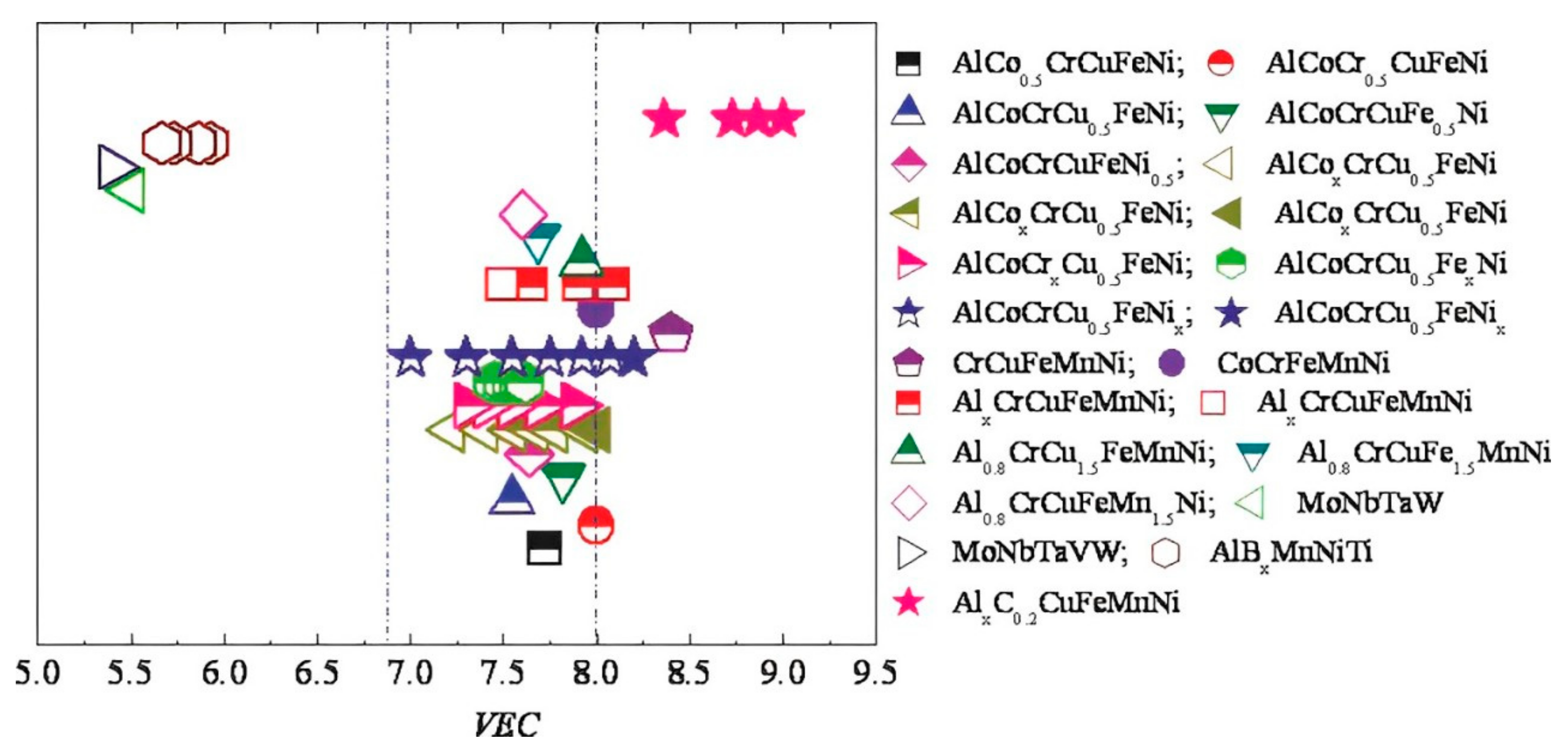
- Guo, S.; Ng, C.; Lu, J.; Liu, C.T. Effect of Valence Electron Concentration on Stability of Fcc or Bcc Phase in High Entropy Alloys. J. Appl. Phys. 2011, 109, 103505. [Google Scholar] [CrossRef]
- Vida, Á.; Chinh, N.Q.; Lendvai, J.; Heczel, A.; Varga, L.K. Microstructures and Transition from Brittle to Ductile Behavior of NiFeCrMoW High Entropy Alloys. Mater. Lett. 2017, 195, 14–17. [Google Scholar] [CrossRef]
- Chen, R.; Qin, G.; Zheng, H.; Wang, L.; Su, Y.; Chiu, Y.; Ding, H.; Guo, J.; Fu, H. Composition Design of High Entropy Alloys Using the Valence Electron Concentration to Balance Strength and Ductility. Acta Mater. 2018, 144, 129–137. [Google Scholar] [CrossRef]
- Zhang, Y.; Ma, S.G.; Qiao, J.W. Morphology Transition from Dendrites to Equiaxed Grains for AlCoCrFeNi High-Entropy Alloys by Copper Mold Casting and Bridgman Solidification. Metall. Mater. Trans. A 2012, 43, 2625–2630. [Google Scholar] [CrossRef]
- Hanna, J.A.; Baker, I.; Wittmann, M.W.; Munroe, P.R. A New High-Strength Spinodal Alloy. J. Mater. Res. 2005, 20, 791–795. [Google Scholar] [CrossRef]
- Wang, W.-R.; Wang, W.-L.; Wang, S.-C.; Tsai, Y.-C.; Lai, C.-H.; Yeh, J.-W. Effects of Al Addition on the Microstructure and Mechanical Property of AlxCoCrFeNi High-Entropy Alloys. Intermetallics 2012, 26, 44–51. [Google Scholar] [CrossRef]
- Wang, W.-R.; Wang, W.-L.; Yeh, J.-W. Phases, Microstructure and Mechanical Properties of AlxCoCrFeNi High-Entropy Alloys at Elevated Temperatures. J. Alloys Compd. 2014, 589, 143–152. [Google Scholar] [CrossRef]
- Yang, T.; Xia, S.; Liu, S.; Wang, C.; Liu, S.; Zhang, Y.; Xue, J.; Yan, S.; Wang, Y. Effects of AL Addition on Microstructure and Mechanical Properties of Al CoCrFeNi High-Entropy Alloy. Mater. Sci. Eng. A 2015, 648, 15–22. [Google Scholar] [CrossRef]
- Zhang, F.X.; Zhao, S.; Jin, K.; Bei, H.; Popov, D.; Park, C.; Neuefeind, J.C.; Weber, W.J.; Zhang, Y. Pressure-Induced Fcc to Hcp Phase Transition in Ni-Based High Entropy Solid Solution Alloys. Appl. Phys. Lett. 2017, 110, 011902. [Google Scholar] [CrossRef]
- Yang, J.X.; Zhao, H.L.; Gong, H.R.; Song, M.; Ren, Q.Q. Proposed Mechanism of HCP → FCC Phase Transition in Titianium through First Principles Calculation and Experiments. Sci. Rep. 2018, 8, 1992. [Google Scholar] [CrossRef]
- Ma, D.; Grabowski, B.; Körmann, F.; Neugebauer, J.; Raabe, D. Ab Initio Thermodynamics of the CoCrFeMnNi High Entropy Alloy: Importance of Entropy Contributions beyond the Configurational One. Acta Mater. 2015, 100, 90–97. [Google Scholar] [CrossRef]
- Weng, S.; Han, W.; Chen, G.; Fu, T. Spatially varied stacking fault energy induced low twinning ability in high entropy alloys. J. Appl. Phys. 2024, 135, 205103. [Google Scholar] [CrossRef]
- Tsao, T.; Yeh, A.; Kuo, C.; Murakami, H. On The Superior High Temperature Hardness of Precipitation Strengthened High Entropy Ni-Based Alloys. Adv. Eng. Mater. 2017, 19, 1600475. [Google Scholar] [CrossRef]
- Reed, R.C.; Tao, T.; Warnken, N. Alloys-By-Design: Application to Nickel-Based Single Crystal Superalloys. Acta Mater. 2009, 57, 5898–5913. [Google Scholar] [CrossRef]
- Kawagishi, K.; Yeh, A.; Yokokawa, T.; Kobayashi, T.; Koizumi, Y.; Harada, H. Development of an Oxidation-Resistant High-Strength Sixth-Generation Single-Crystal Superalloy TMS-238. In Superalloys; Wiley: Michigan, MI, USA, 2012; pp. 189–195. [Google Scholar]
- Reed, R.C. The Superalloys; Cambridge University Press: Cambridge, UK, 2006; ISBN 9780521859042. [Google Scholar]
- Sugui, T.; Minggang, W.; Tang, L.; Benjiang, Q.; Jun, X. Influence of TCP Phase and Its Morphology on Creep Properties of Single Crystal Nickel-Based Superalloys. Mater. Sci. Eng. A 2010, 527, 5444–5451. [Google Scholar] [CrossRef]
- López Ríos, M.; Socorro Perdomo, P.P.; Voiculescu, I.; Geanta, V.; Crăciun, V.; Boerasu, I.; Mirza Rosca, J.C. Effects of Nickel Content on the Microstructure, Microhardness and Corrosion Behavior of High-Entropy AlCoCrFeNix Alloys. Sci. Rep. 2020, 10, 21119. [Google Scholar] [CrossRef]
- Li, Z.; Pradeep, K.G.; Deng, Y.; Raabe, D.; Tasan, C.C. Metastable High-Entropy Dual-Phase Alloys Overcome the Strength–Ductility Trade-Off. Nature 2016, 534, 227–230. [Google Scholar] [CrossRef]
- Zhang, C.; Zhang, F.; Diao, H.; Gao, M.C.; Tang, Z.; Poplawsky, J.D.; Liaw, P.K. Understanding Phase Stability of Al-Co-Cr-Fe-Ni High Entropy Alloys. Mater. Des. 2016, 109, 425–433. [Google Scholar] [CrossRef]
- Yasuda, H.Y.; Miyamoto, H.; Cho, K.; Nagase, T. Formation of Ultrafine-Grained Microstructure in Al0.3CoCrFeNi High Entropy Alloys with Grain Boundary Precipitates. Mater. Lett. 2017, 199, 120–123. [Google Scholar] [CrossRef]
- He, J.Y.; Liu, W.H.; Wang, H.; Wu, Y.; Liu, X.J.; Nieh, T.G.; Lu, Z.P. Effects of Al Addition on Structural Evolution and Tensile Properties of the FeCoNiCrMn High-Entropy Alloy System. Acta Mater. 2014, 62, 105–113. [Google Scholar] [CrossRef]
- Gorsse, S.; Nguyen, M.H.; Senkov, O.N.; Miracle, D.B. Database on the Mechanical Properties of High Entropy Alloys and Complex Concentrated Alloys. Data Brief 2018, 21, 2664–2678. [Google Scholar] [CrossRef]
- Gawel, R.; Rogal, Ł.; Grzesik, Z. Behaviour of Al, Co, Cr, Ni-Based High Entropy Alloys under High-Temperature Thermal Shock Oxidising Conditions. Corros. Sci. 2022, 198, 110116. [Google Scholar] [CrossRef]
- Ng, C.; Guo, S.; Luan, J.; Shi, S.; Liu, C.T. Entropy-Driven Phase Stability and Slow Diffusion Kinetics in an Al0.5CoCrCuFeNi High Entropy Alloy. Intermetallics 2012, 31, 165–172. [Google Scholar] [CrossRef]
- Butler, T.M.; Alfano, J.P.; Martens, R.L.; Weaver, M.L. High-Temperature Oxidation Behavior of Al-Co-Cr-Ni-(Fe or Si) Multicomponent High-Entropy Alloys. JOM 2015, 67, 246–259. [Google Scholar] [CrossRef]
- Talkar, S.; Choudhari, A.; Rayar, P. Building Envelope Optimization and Cost-Effective Approach in HVAC to Support Smart Manufacturing. In Proceedings of the International Conference on Intelligent Manufacturing and Automation, Mostar, Bosnia and Herzegovina, 21–24 October 2020; Springer: Singapore, 2020. [Google Scholar]
- Sharma, P. Electro-Spark Coating of High Entropy Alloy on Steel and Inconel Superalloy for Surface Hardening and Oxidation Protection. Master’s Dissertation, Indian Institute of Technology Hyderabad, Kandi, India, 2020. [Google Scholar]
- Jumaev, E.; Hong, S.H.; Kim, J.T.; Park, H.J.; Kim, Y.S.; Mun, S.C.; Park, J.-Y.; Song, G.; Lee, J.K.; Min, B.H.; et al. Chemical Evolution-Induced Strengthening on AlCoCrNi Dual-Phase High-Entropy Alloy with High Specific Strength. J. Alloys Compd. 2019, 777, 828–834. [Google Scholar] [CrossRef]
- Gyawali, S.; Tirumala, R.T.A.; Loh, H.; Andiappan, M.; Bristow, A.D. Photocarrier Recombination Dynamics in Highly Scattering Cu2O Nanocatalyst Clusters. J. Phys. Chem. C 2024, 128, 2003–2011. [Google Scholar] [CrossRef]
- Gyawali, S.; Tirumala, R.T.A.; Andiappan, M.; Bristow, A.D. Size- and Shape-Dependent Charge-Carrier Dynamics in Sub-Micron Cuprous Oxide Nanoparticles. In Proceedings of the Frontiers in Optics + Laser Science 2022 (FIO, LS), Rochester, NT, USA, 18–19 October 2022; Optica Publishing Group: Washington, DC, USA, 2022; p. JTu4A.86. [Google Scholar] [CrossRef]
- Gyawali, S.; Tirumala, R.T.A.; Andiappan, M.; Bristow, A.D. Carrier Dynamics in Cuprous Oxide-Based Nanoparticles and Heterojunctions. In Proceedings of the Ultrafast Phenomena and Nanophotonics XXVIII, San Francisco, CA, USA, 29–31 January 2024; Betz, M., Elezzabi, A.Y., Eds.; SPIE: New York, NY, USA, 2024; Volume 12884, p. 128840F. [Google Scholar] [CrossRef]


| n | ΔSconf |
|---|---|
| 1 | 0 |
| 2 | 0.69R |
| 3 | 1.10R |
| 4 | 1.39R |
| 5 | 1.61R |
| 6 | 1.79R |
| 7 | 1.95R |
| 8 | 2.08R |
| 9 | 2.20R |
| 10 | 2.30R |
| 11 | 2.40R |
| 12 | 2.49R |
| 13 | 2.57R |
| System | Alloys | ∆Sconf at Liquid State |
|---|---|---|
| Low-Alloy Steel | 4340 | 0.22R low |
| Stainless Steel | 304 | 0.96R low |
| 316 | 1.15R medium | |
| High speed Steel | M2 | 0.73R low |
| Mg Alloy | AZ91D | 0.35R low |
| Al Alloy | 2024 | 0.29R low |
| 7075 | 0.43R low | |
| Cu-alloy | brass | 0.61R low |
| Ni-Base Superalloy | Inconel 718 | 1.31 medium |
| Hastealloy | 1.37 medium | |
| Co-Base Superalloy | Stellite 6 | 1.13 medium |
| BMG | Cu47Zr11Ti34Ni8 | 1.17 medium |
| Zr53Ti5Cu16Ni10Al16 | 1.3 medium |
| Major Metallic Elements | Minor Metallic Elements | Minor Non-Metallic Elements |
|---|---|---|
| Li, Be, Mg | Li, Be, Mg | C, B, Si, P |
| Al, Sc, Ti, V, | Sc, Ti, V, Cr, Fe | S, O, N |
| Cr, Fe, Co, Ni, | Co, Ni, Cu, Zn, | |
| Cu, Zn, Y, Zr | Ga, Ge, Sy, Cd | |
| Nb, Mo, Sm | Ln, Sn, Sb, Y | |
| Eu, Au, Gd, | Zr, Nb, Mo, Ru | |
| Tb, Rh, Pb, | Rh, Pb, Bi, Pd, | |
| Pd, Ag, Hf, Ta | Ag, Hf, Ta, W, Pt, | |
| W, Pt, Nd | Au, La, Ce, | |
| Pr, Nd, Sm, Fu. | ||
| Gd, Tb |
| Samples | Ni | Al | Co | Cr | Fe | Ti | Ta | Mo | W | ∆Smix [-R] |
|---|---|---|---|---|---|---|---|---|---|---|
| HESA-1 | 40.7 | 7.8 | 20.6 | 12.2 | 11.5 | 7.2 | - | - | - | 1.58 |
| HESA-2 | 48.6 | 10.3 | 17 | 7.5 | 9 | 5.8 | 0.6 | 0.8 | 0.4 | 1.56 |
| Samples | Ni | Al | Co | Cr | Fe | Ti | Ta | Mo | W | Re | Ru | |
|---|---|---|---|---|---|---|---|---|---|---|---|---|
| Ƴ | HESA-1 | 32.3 | 4.8 | 24.7 | 18.2 | 16.1 | 3.9 | - | - | - | - | - |
| HESA-2 | 40.1 | 6.2 | 22.5 | 12 | 14.3 | 2.4 | 0.5 | 1.4 | 0.6 | - | - | |
| CM247LC | 64.9 | 8.7 | 11 | 10.5 | - | 0.7 | 0.9 | 0.2 | 3.1 | - | - | |
| ME15 | 53.7 | 3.6 | 14.8 | 20.8 | 0.1 | - | 0.1 | 1.3 | 3.5 | 21 | - | |
| Rene’ N5 | 57.8 | 5.3 | 12.8 | 17.9 | - | - | 0.1 | 1.8 | 1.8 | 25 | - | |
| RR2100 | 49.1 | 3.1 | 26.8 | 9.5 | - | - | 0.3 | - | 3.7 | 7.5 | - | |
| RR2101 | 46 | 3.1 | 26.7 | 9.5 | - | - | 0.3 | - | 3.6 | 7.9 | 2.9 | |
| Ƴ | HESA-1 | 54.4 | 9.9 | 13.7 | 4.3 | 5.7 | 12 | - | - | - | - | - |
| HESA-2 | 56.2 | 10.9 | 12.3 | 3.8 | 5.4 | 9.2 | 1.2 | 0.6 | 0.4 | - | - | |
| CM247LC | 69.4 | 15.5 | 5.8 | 3.4 | - | 1.4 | 2.3 | 0.1 | 2.1 | - | - | |
| ME15 | 69 | 17.7 | 5.3 | 2.5 | 0 | - | 1.9 | 0.5 | 2.9 | 0.2 | - | |
| Rene’ N5 | 74.5 | 15.7 | 4.3 | 2.6 | - | - | 1 | 0.5 | 1.2 | 0.2 | - | |
| RR2100 | 67.1 | 16.9 | 8.6 | 1.4 | - | - | 2.6 | - | 2.9 | 0.5 | - | |
| RR2101 | 66.1 | 16.6 | 8.8 | 1.4 | - | - | 2.7 | - | 3 | 0.5 | 0.9 |
| Designation | Nominal Chemical Composition [at.%] | |||||
|---|---|---|---|---|---|---|
| Al | Co | Cr | Fe | Ni | Si | |
| Al25Co25Cr25Ni25 | 25 | 25 | 25 | 0 | 25 | 0 |
| Al20Co25Cr25Ni25Si5 | 20 | 25 | 25 | 0 | 25 | 5 |
| Al9.1Co18.2Cr18.2Fe18.2Ni36.3 | 9.1 | 18.2 | 18.2 | 18.2 | 36.3 | 0 |
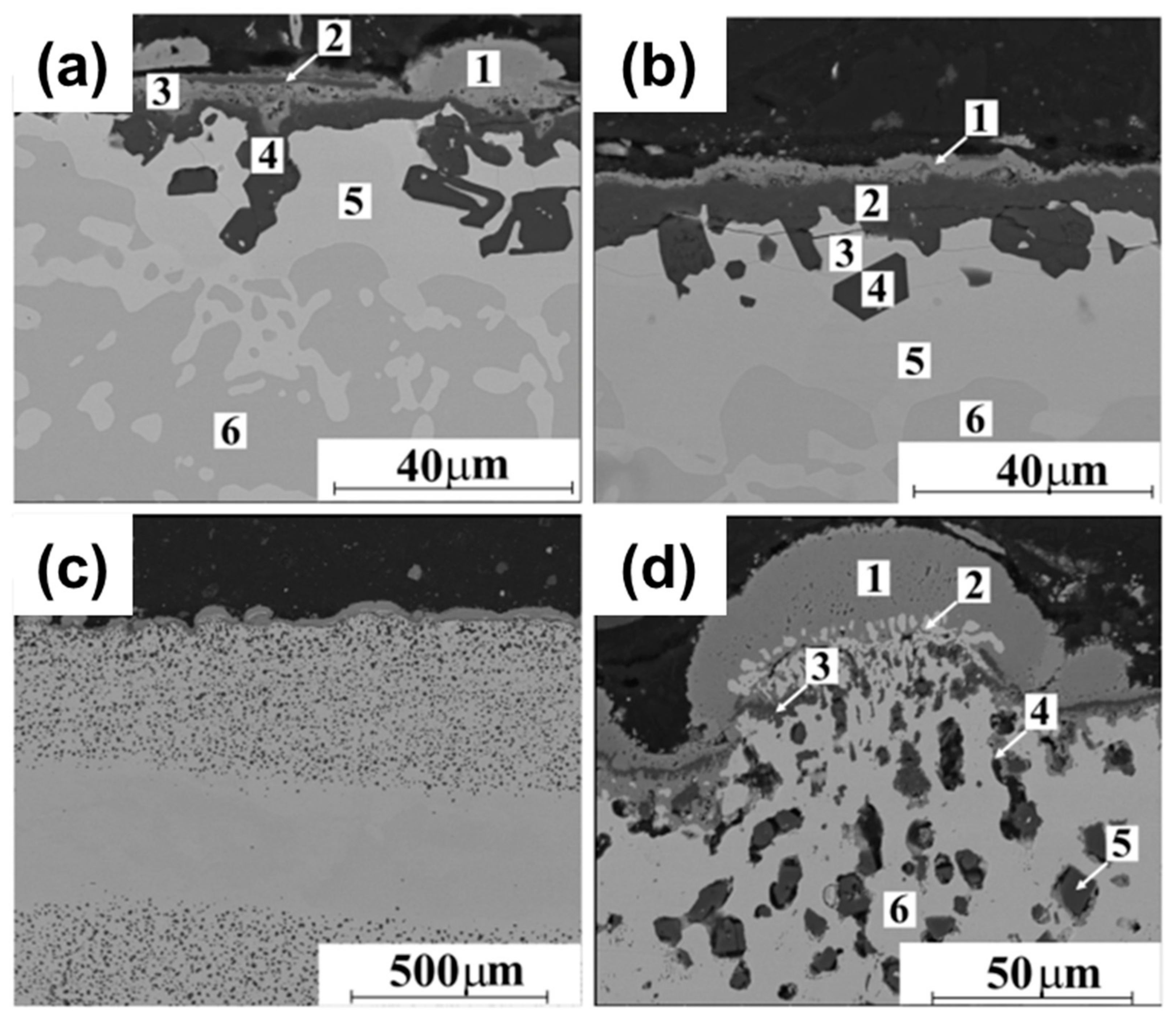
| Sample | Point | Element [at.%] | ||||||
|---|---|---|---|---|---|---|---|---|
| Al | Co | Cr | Fe | Ni | Si | O | ||
| Al25Co25Cr25Ni25 (Figure 16a) | 1 | 0.6 | 1.2 | 55.4 | 0.0 | 1.4 | 0.0 | 41.4 |
| 2 | 35.2 | 3.5 | 7.3 | 0.0 | 5.3 | 0.0 | 43.7 | |
| 3 | 20.3 | 13.7 | 19.3 | 0.0 | 11.0 | 0.0 | 35.2 | |
| 4 | 36.7 | 1.0 | 1.4 | 0.0 | 0.0 | 0.0 | 10.9 | |
| 5 | 5.0 | 38.2 | 30.4 | 0.0 | 20.3 | 0.0 | 5.6 | |
| 6 | 26.2 | 22.2 | 8.1 | 0.0 | 41.3 | 0.0 | 2.2 | |
| Al20Co25Cr25Ni25Si5 (Figure 16b) | 1 | 2.2 | 0.9 | 51.3 | 0.0 | 1.5 | 0.0 | 44.1 |
| 2 | 84.7 | 0.4 | 1.9 | 0.0 | 0.0 | 0.0 | 13.0 | |
| 3 | 1.8 | 26.4 | 46.3 | 0.0 | 9.2 | 7.8 | 3.5 | |
| 4 | 98.5 | 0.0 | 0.7 | 0.0 | 0.2 | 0.6 | 0.0 | |
| 5 | 4.2 | 35.5 | 23.2 | 0.0 | 21.3 | 5.1 | 5.7 | |
| 6 | 24.6 | 22.1 | 3.9 | 0.0 | 37.9 | 3.3 | 3.2 | |
| Al9.1Co18.2Cr18.2Fe18.2Ni36.3 (Figure 16d) | 1 | 0.4 | 0.6 | 54.5 | 1.3 | 1.0 | 0.0 | 42.2 |
| 2 | 1.7 | 18.6 | 15.9 | 19.4 | 34.6 | 0.0 | 9.8 | |
| 3 | 50.3 | 0.7 | 4.5 | 0.3 | 0.4 | 0.0 | 43.3 | |
| 4 | 15.3 | 1.4 | 41.3 | 1.9 | 1.7 | 0.0 | 38.3 | |
| 5 | 99.6 | 0.0 | 0.4 | 0.0 | 0.0 | 0.0 | 0.0 | |
| 6 | 3.0 | 18.1 | 11.2 | 20.1 | 36.2 | 0.0 | 11.4 | |
Disclaimer/Publisher’s Note: The statements, opinions and data contained in all publications are solely those of the individual author(s) and contributor(s) and not of MDPI and/or the editor(s). MDPI and/or the editor(s) disclaim responsibility for any injury to people or property resulting from any ideas, methods, instructions or products referred to in the content. |
© 2024 by the authors. Licensee MDPI, Basel, Switzerland. This article is an open access article distributed under the terms and conditions of the Creative Commons Attribution (CC BY) license (https://creativecommons.org/licenses/by/4.0/).
Share and Cite
Gupta, A.K.; Choudhari, A.; Rane, A.; Tiwari, A.; Sharma, P.; Gupta, A.; Sapale, P.; Tirumala, R.T.A.; Muthaiah, R.; Kumar, A. Advances in Nickel-Containing High-Entropy Alloys: From Fundamentals to Additive Manufacturing. Materials 2024, 17, 3826. https://doi.org/10.3390/ma17153826
Gupta AK, Choudhari A, Rane A, Tiwari A, Sharma P, Gupta A, Sapale P, Tirumala RTA, Muthaiah R, Kumar A. Advances in Nickel-Containing High-Entropy Alloys: From Fundamentals to Additive Manufacturing. Materials. 2024; 17(15):3826. https://doi.org/10.3390/ma17153826
Chicago/Turabian StyleGupta, Ashish Kumar, Amit Choudhari, Aditya Rane, Abhishek Tiwari, Prince Sharma, Ashutosh Gupta, Prathamesh Sapale, Ravi Teja A. Tirumala, Rajmohan Muthaiah, and Abhishek Kumar. 2024. "Advances in Nickel-Containing High-Entropy Alloys: From Fundamentals to Additive Manufacturing" Materials 17, no. 15: 3826. https://doi.org/10.3390/ma17153826