
A Study of the Effects of Moisture on Composite−to−Metal Double−Lap Shear Joints


Abstract
1. Introduction
2. Materials and Experiments
2.1. Materials and Specimens
2.2. Experiments
2.2.1. Moisture Absorption Tests
2.2.2. Mechanical Tests
3. Results
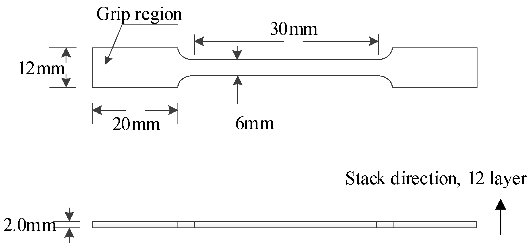
3.1. Adhesive Tensile Tests
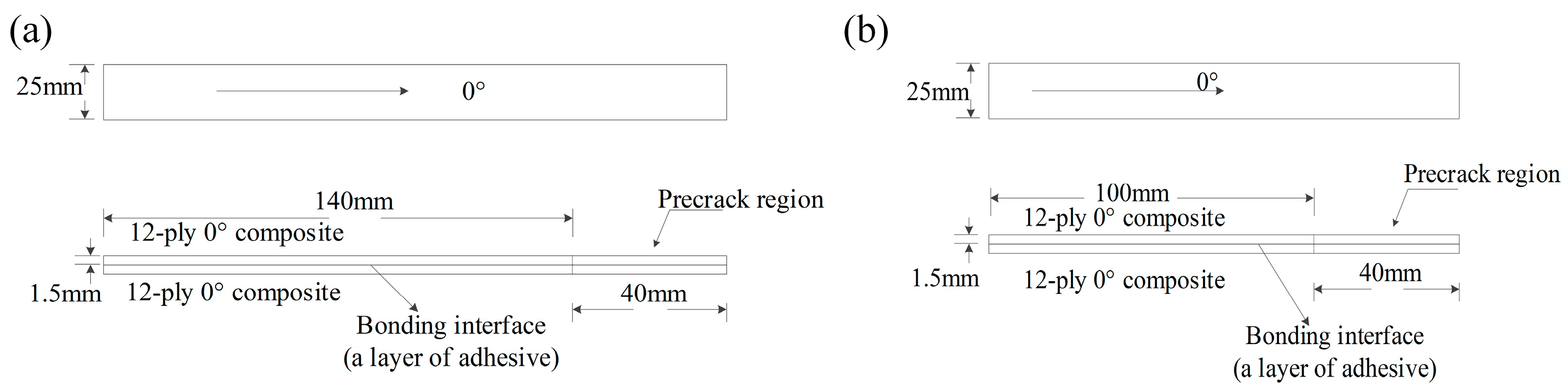
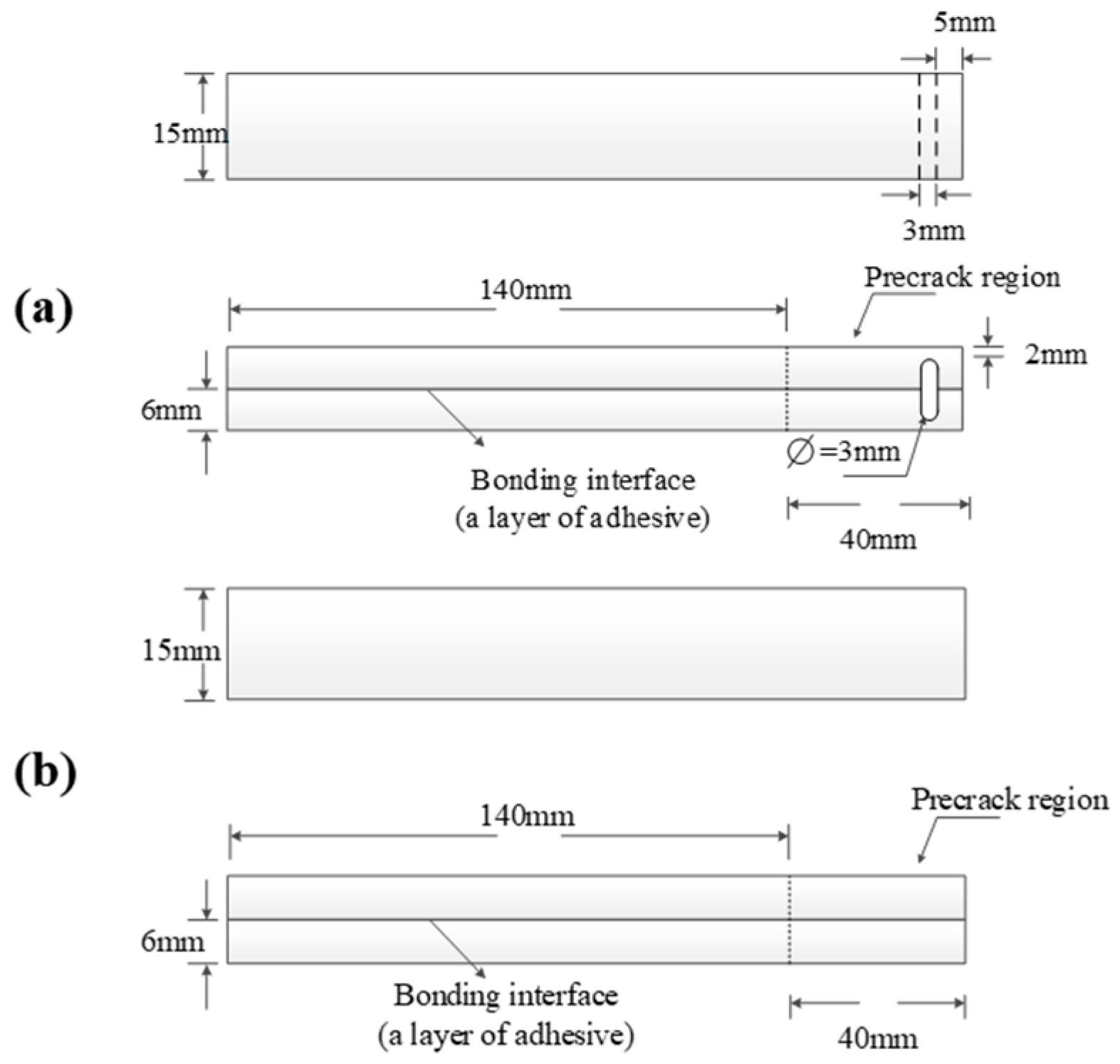
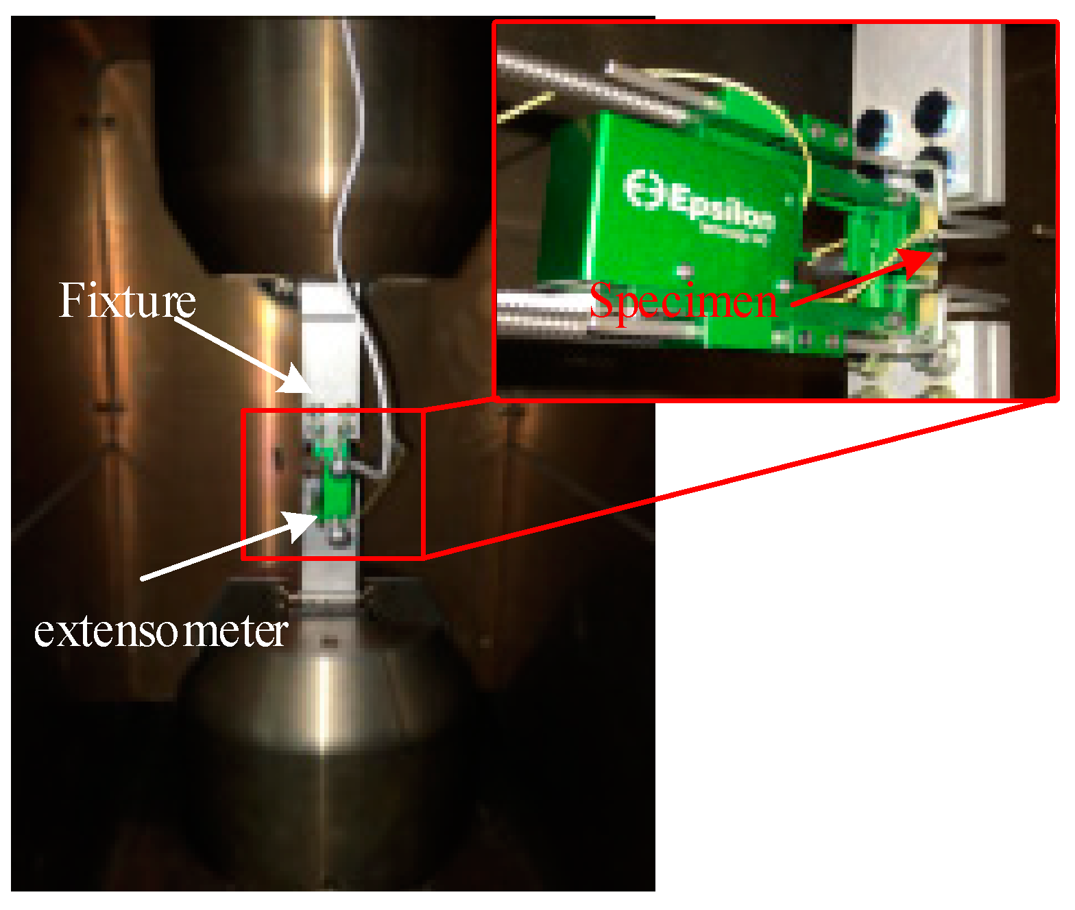
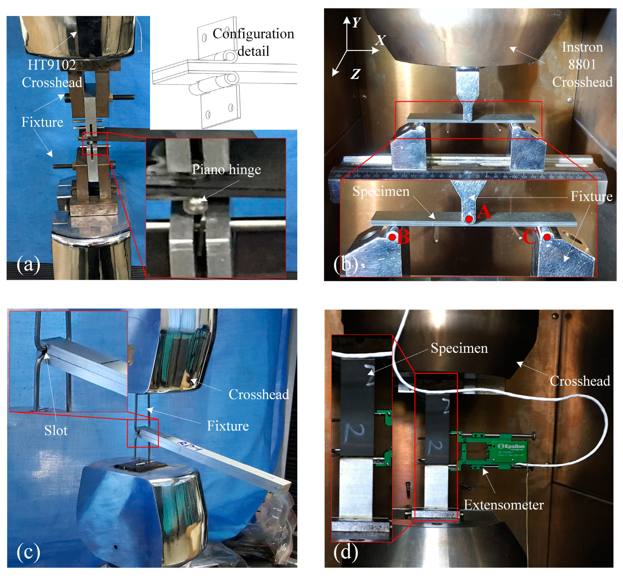
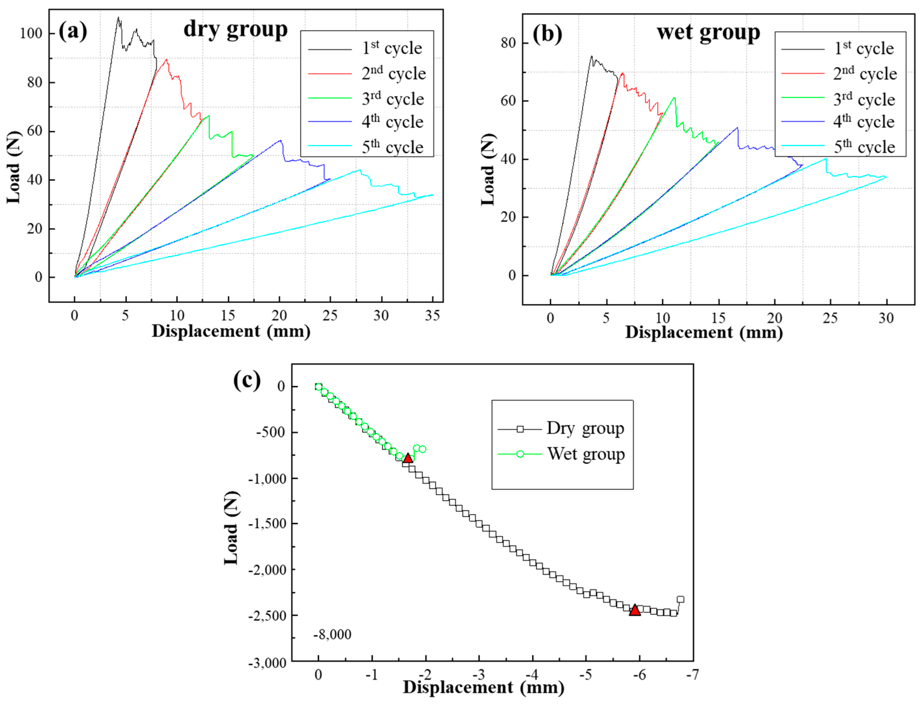
3.2. GC Tests
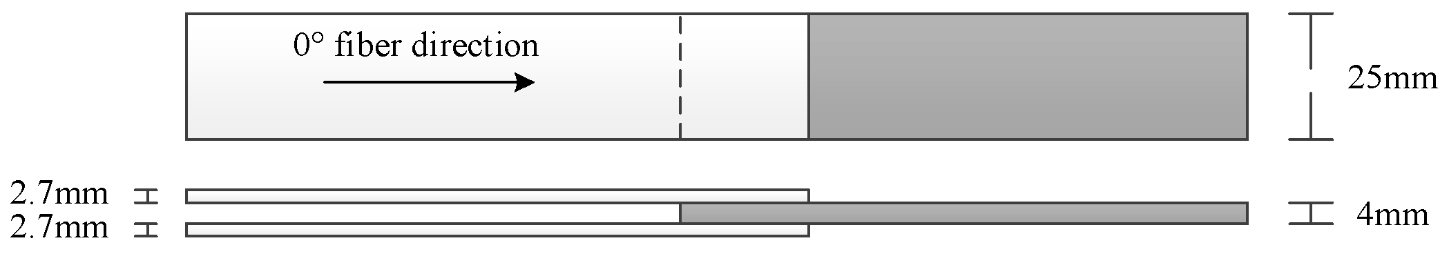
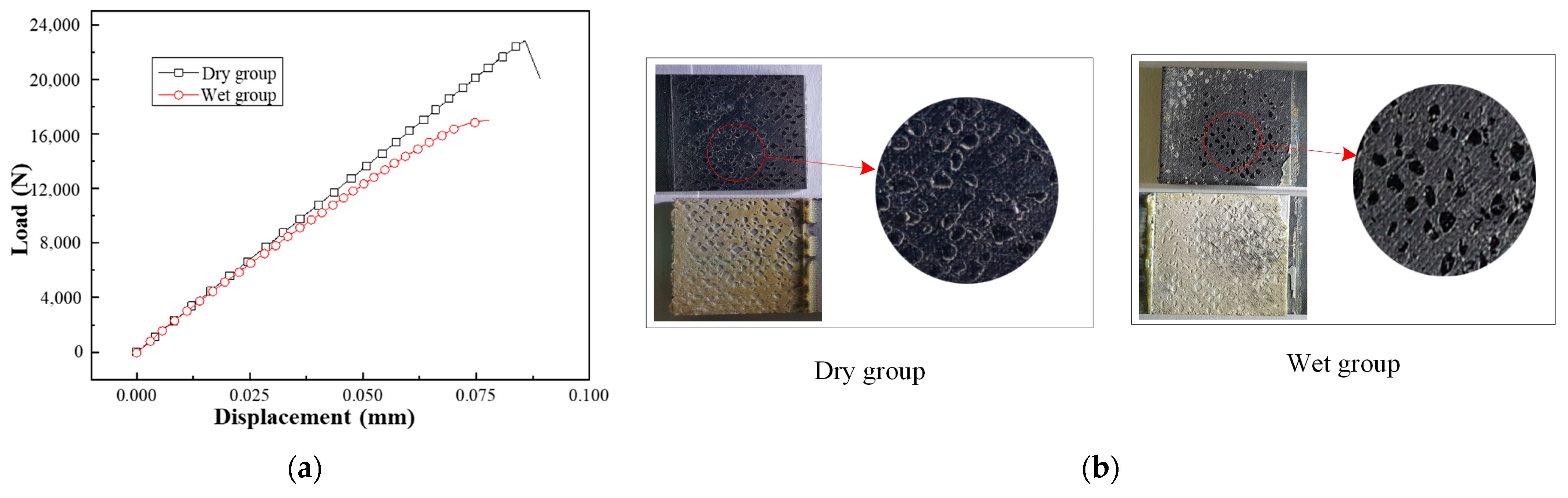
3.3. Double−Lap Shear Joints
4. FE Analysis
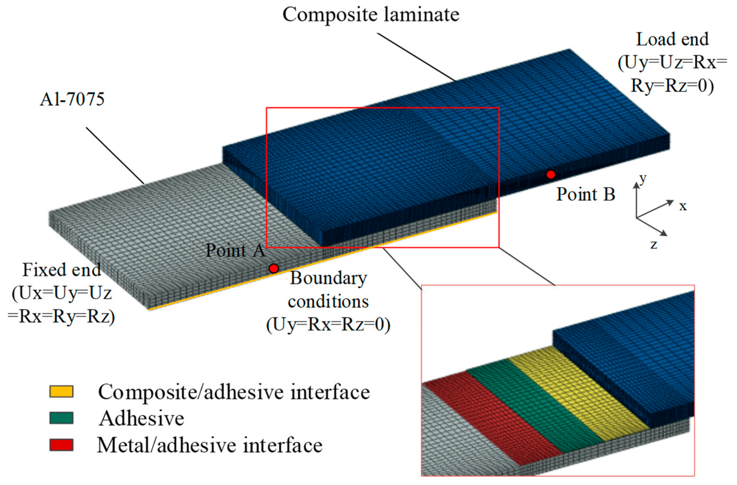
4.1. FE Model
4.2. Damage Criteria and Degradation Rules
4.3. The Stress−Strain Relationship under the Wet Environment
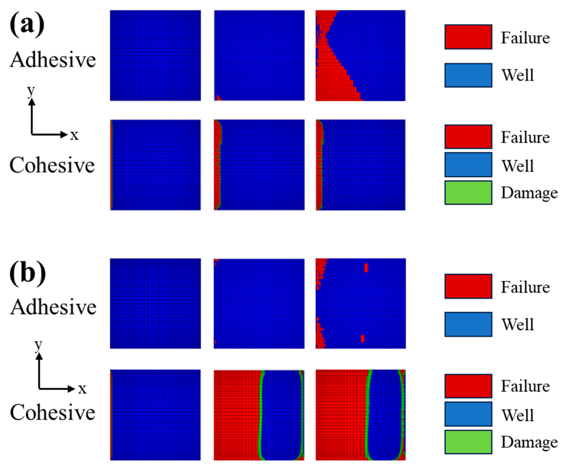
4.4. FE Results for DLSJs
5. Conclusions
- (1)
- The moist environment significantly influences the tensile strength and modulus of the adhesive, decreasing by approximately 28.1% and 30.9%, respectively.
- (2)
- In the composite/adhesive fracture energy tests, the GIC and GIIC decreased by 32.6% and 91.2%, respectively, after immersion in 95 °C water for 40 d. In the metal/adhesive fracture energy tests, the GIC and GIIC decreased by 33.5% and 67.4%, respectively, after immersion in 95 °C water for 29 d.
- (3)
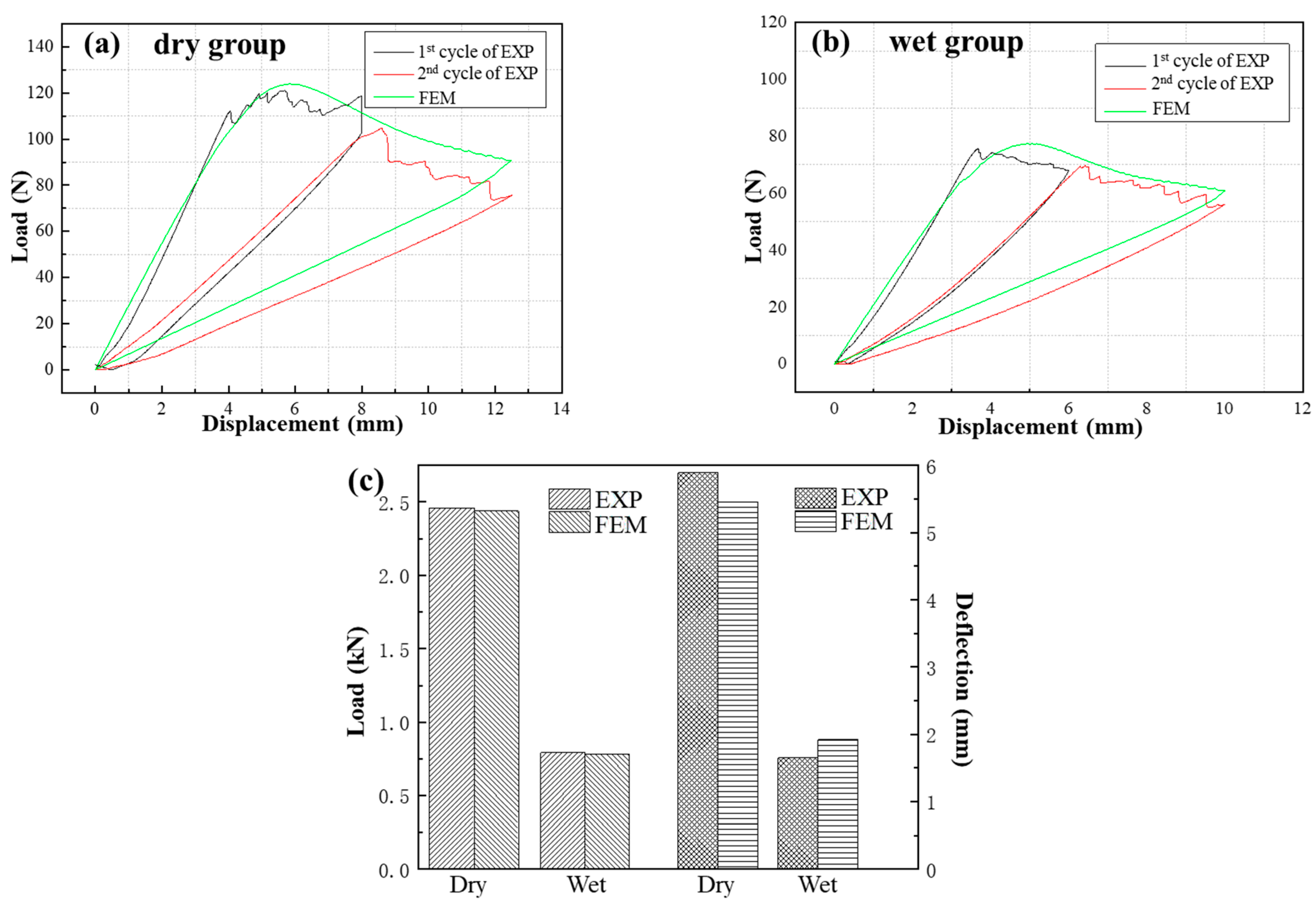
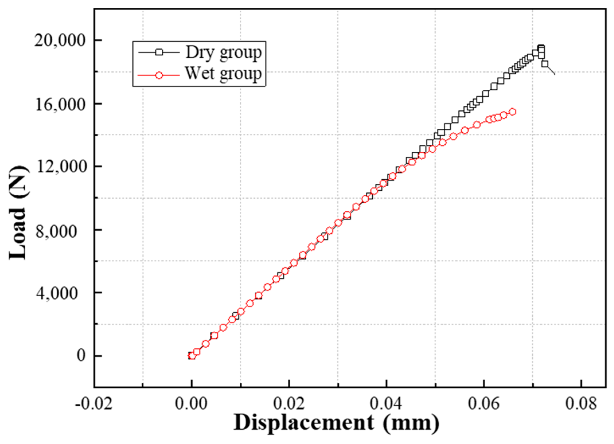
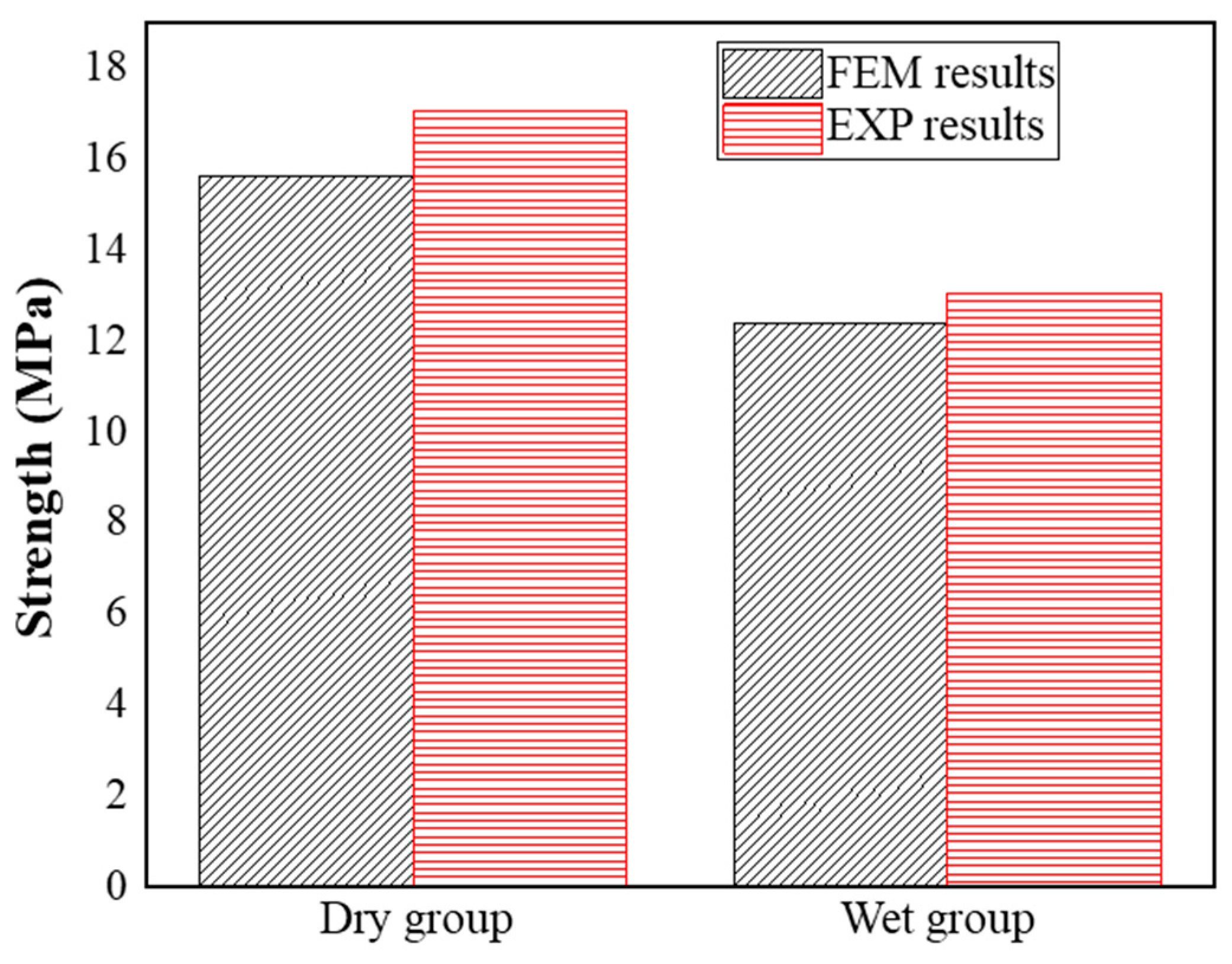
- The ultimate load of the wet group specimens decreased by almost 25.4% after immersion in 95 °C water for 50 d, while the initial stiffness (the slope of the load) of the DLSJ specimens in different environments was nearly invariable, indicating that joint strength is significantly affected by the wet environment; however, the influence on joint stiffness can be ignored.
- (4)
- The failure modes of the DLSJs under dry and wet environments differed. The main damage was an adhesive failure in the dry group, while the interlaminar failure was the main damage in the wet group.
- (5)
- The predicted results of the failure loads of the DLSJs under tensile loading for the dry and wet groups obtained using FEM had errors of -8.5% and 5.0%, respectively, compared with the results of the tests. The damage evolution obtained through FEM also showed good consistency with EXP.
Author Contributions
Funding
Institutional Review Board Statement
Informed Consent Statement
Data Availability Statement
Conflicts of Interest
References
- Valenza, A.; Fiore, V.; Fratini, L. Mechanical behavior and failure modes of metal to composite adhesive joints for nautical applications. Int. J. Adv. Manuf. Technol. 2011, 53, 593–600. [Google Scholar] [CrossRef]
- Liu, B.; Xu, F.; Feng, W.; Yan, R.; Xie, W. Experiment and design methods of composite scarf repair for primary-load bearing structures. Compos. Part A Appl. Sci. Manuf. 2016, 88, 27–38. [Google Scholar] [CrossRef]
- Barreira-Pinto, R.; Carneiro, R.; Miranda, M.; Guedes, R.M. Polymer-Matrix Composites: Characterising the Impact of Environmental Factors on Their Lifetime. Materials 2023, 16, 3913. [Google Scholar] [CrossRef] [PubMed]
- Liu, H.; Sun, J.; Zhang, L.; Liu, Z.; Huang, C.; Sun, M.; Duan, Z.; Wang, W.; Zhong, X.; Bao, J. Influence of the Second-Phase Resin Structure on the Interfacial Shear Strength of Carbon Fiber/Epoxy Resin. Materials 2024, 17, 1323. [Google Scholar] [CrossRef] [PubMed]
- Li, W.; Ma, Z.; Shen, P.; Luo, C.; Zhong, X.; Jiang, S.; Bai, W.; Xie, L.; Hu, X.; Bao, J. Preparation and Validation of a Longitudinally and Transversely Stiffened Panel Based on Hybrid RTM Composite Materials. Materials 2023, 16, 5156. [Google Scholar] [CrossRef] [PubMed]
- Liu, S.; Zhang, J.; Guo, X.; Cheng, X.; Bao, J. An investigation of hygrothermal effects on adhesive materials and double lap shear joints of CFRP composite laminates. Compos. Part B Eng. 2016, 91, 431–440. [Google Scholar] [CrossRef]
- Whitehouse, A.D.; Médeau, V.; Mencattelli, L.; Blackman, B.; Pinho, S.T. A novel profiling concept leading to a significant increase in the mechanical performance of metal to composite adhesive joints. Compos. Part B Eng. 2023, 261, 110791. [Google Scholar] [CrossRef]
- Liu, Z.; Li, Y.; Liu, W.; Zhou, H.; Ao, S.; Luo, Z. Enhancing the ultrasonic plastic welding strength of Al/CFRTP joint via coated metal surface and structured composite surface. J. Manuf. Process. 2023, 108, 227–237. [Google Scholar] [CrossRef]
- Feng, Z.; Zhang, X.; Qin, C.; Su, J.; Tan, C.; Zhao, H.; Chen, B.; Song, X. Improvement of interfacial thermal contact conductance and mechanical performance of metal-composite joint via controlling anchoring structures. Thin-Walled Struct. 2024, 200, 111882. [Google Scholar] [CrossRef]
- Inverarity, S.B.; Das, R.; Mouritz, A.P. Composite-to-metal joining using interference fit micropins. Compos. Part A Appl. Sci. Manuf. 2022, 156, 106895. [Google Scholar] [CrossRef]
- Loh, W.K.; Crocombe, A.D.; Wahab, M.M.A.; Ashcroft, I.A. Modelling anomalous moisture uptake, swelling and thermal characteristics of a rubber toughened epoxy adhesive. Int. J. Adhes. Adhes. 2005, 25, 1–12. [Google Scholar] [CrossRef]
- Campilho, R.D.S.G.; Moura, M.F.S.F.D.; Domingues, J.J.M.S. Using a cohesive damage model to predict the tensile behaviour of CFRP single-strap repairs. Int. J. Solids Struct. 2008, 45, 1497–1512. [Google Scholar] [CrossRef]
- Zheng, L.; Yoon, J.W. A new failure criterion for predicting meso/micro-scale forming limit of composite metal foils. Int. J. Plast. 2024, 176, 103962. [Google Scholar] [CrossRef]
- Tserpes, K.; Sioutis, I.; Floros, G.; Moutsompegka, E. Numerical simulation of debonding of a composite-to-metal adhesive joint subjected to centrifugal load. Eng. Fail. Anal. 2022, 136, 106131. [Google Scholar] [CrossRef]
- Rouhi, M.S.; Ramantani, D.; Tay, T.E. 3D explicit simulation of bearing failure in metal–composite bolted joints. Compos. Struct. 2022, 284, 115108. [Google Scholar] [CrossRef]
- Ridha, M.; Tan, V.B.C.; Tay, T.E. Traction–separation laws for progressive failure of bonded scarf repair of composite panel. Compos. Struct. 2011, 93, 1239–1245. [Google Scholar] [CrossRef]
- Shindo, Y.; Horiguchi, K.; Wang, R.; Kudo, H. Double Cantilever Beam Measurement and Finite Element Analysis of Cryogenic Mode I Interlaminar Fracture Toughness of Glass-Cloth/Epoxy Laminates. J. Eng. Mater. Technol. 2001, 123, 191–197. [Google Scholar] [CrossRef]
- Balzani, C.; Wagner, W.; Wilckens, D.; Degenhardt, R.; Büsing, S. Adhesive joints in composite laminates—A combined numerical/experimental estimate of critical energy release rates. Int. J. Adhes. Adhes. 2011, 32, 23–38. [Google Scholar] [CrossRef]
- Gong, Y.; Zhao, L.; Zhang, J.; Wang, Y.; Hu, N. Delamination propagation criterion including the effect of fiber bridging for mixed-mode I/II delamination in CFRP multidirectional laminates. Compos. Sci. Technol. 2017, 151, 302–309. [Google Scholar] [CrossRef]
- Li, F.-H.; Han, B.; Zhang, A.-H.; Liu, K.; Wang, Y.; Lu, T.-J. A Three-Dimensional Vibration Theory for Ultralight Cellular Sandwich Plates Subjected to Linearly Varying In-Plane Distributed Loads. Materials 2023, 16, 4086. [Google Scholar] [CrossRef]
- Cheng, X.; Zhang, J.; Bao, J.; Zeng, B.; Cheng, Y.; Hu, R. Low-velocity impact performance and effect factor analysis of scarf-repaired composite laminates—ScienceDirect. Int. J. Impact Eng. 2018, 111, 85–93. [Google Scholar] [CrossRef]
- Anyfantis, K.N.; Tsouvalis, N.G. A 3D ductile constitutive mixed-mode model of cohesive elements for the finite element analysis of adhesive joints. Solids Struct. 2012, 49, 213–226. [Google Scholar] [CrossRef]
- Anyfantis, K.N.; Tsouvalis, N.G. Loading and fracture response of CFRP-to-steel adhesively bonded joints with thick adherents—Part II: Numerical simulation. Compos. Struct. 2013, 96, 858–868. [Google Scholar] [CrossRef]
- Anyfantis, K.N.; Tsouvalis, N.G. Loading and fracture response of CFRP-to-steel adhesively bonded joints with thick adherents—Part I: Experiments. Compos. Struct. 2013, 96, 850–857. [Google Scholar] [CrossRef]
- Shin, K.C.; Lim, J.O.; Lee, J.J. The manufacturing process of co-cured single and double lap joints and evaluation of the load-bearing capacities of co-cured joints. J. Mater. Process. Technol. 2003, 138, 89–96. [Google Scholar] [CrossRef]
- Park, S.W.; Kim, H.S.; Lee, D.G. Optimum design of the co-cured double lap joint composed of aluminum and carbon epoxy composite. Compos. Struct. 2006, 75, 289–297. [Google Scholar] [CrossRef]
- Tsouvalis, N.G.; Karatzas, V.A. An Investigation of the Tensile Strength of a Composite-to-Metal Adhesive Joint. Appl. Compos. Mater. 2010, 18, 149–163. [Google Scholar] [CrossRef]
- Knight, G.A.; Hou, T.H.; Belcher, M.A.; Palmieri, F.L.; Wohl, C.J.; Connell, J.W. Hygrothermal aging of composite single lap shear specimens comprised of AF-555M adhesive and T800H/3900-2 adherends. Int. J. Adhes. Adhes. 2012, 39, 1–7. [Google Scholar] [CrossRef]
- ASTM D5528-13; Standard Test Method for Mode I Interlaminar Fracture Toughness of Unidirectional Fiber-Reinforced Polymer Matrix Composites. American Society for Testing and Materials: West Conshohokken, PA, USA, 2013.
- ASTM D7905M-14; Standard Test Method for Determination of the Mode II Interlaminar Fracture Toughness of Unidirectional Fiber-Reinforced Polymer Matrix Composites. American Society for Testing and Materials: West Conshohokken, PA, USA, 2014.
- Liu, S.; Cheng, X.; Zhang, Q.; Zhang, J.; Bao, J.; Guo, X. Parameters prediction of cohesive zone model for simulating composite/adhesive delamination in hygrothermal environments. Compos. Part B Eng. 2019, 166, 710–721. [Google Scholar]
- ASTM D3528 (2008); Standard Test Method for Strength Properties of Double Lap Shear Adhesive Joints by Tension Loading. American Society for Testing and Materials: West Conshohokken, PA, USA, 2008.
- Xu, Y.; Cheng, X.; Zhang, J.; Li, Z. Study on composite honeycomb sandwich structure formed t-joints under tensile load. Eng. Mech. 2015, 32, 243–248. [Google Scholar]
- Hashin, Z. Fatigue Failure Criteria for Unidirectional Fiber Composites. J. Appl. Mech. 1981, 47, 329–334. [Google Scholar] [CrossRef]
- Tan, S.C. A Progressive Failure Model for Composite Laminates Containing Openings. J. Compos. Mater. 1991, 25, 556–577. [Google Scholar] [CrossRef]
- Liu, S.; Cheng, X.; Xu, Y.; Bao, J.; Guo, X. Study on impact performances of scarf-repaired carbon fiber reinforced polymer laminates. J. Reinf. Plast. Compos. 2014, 34, 60–71. [Google Scholar]
- Sugiman, S.; Crocombe, A.D.; Aschroft, I.A. Experimental and numerical investigation of the static response of environmentally aged adhesively bonded joints. Int. J. Adhes. Adhes. 2013, 40, 224–237. [Google Scholar] [CrossRef]
- Abaqus-Inc. Abaqus User Manual, Version 6.11; Dassault Systemes Simulia Corp: Providence, RI, USA, 2012. [Google Scholar]
- Benkhedda, A.; Tounsi, A.; Adda bedia, E.A. Effect of temperature and humidity on transient hygrothermal stresses during moisture desorption in laminated composite plates. Compos. Struct. 2008, 82, 629–635. [Google Scholar] [CrossRef]
- Kundu, C.K.; Han, J.H. Nonlinear buckling analysis of hygrothermoelastic composite shell panels using finite element method. Compos. Part B Eng. 2009, 40, 313–328. [Google Scholar] [CrossRef]


| Properties | Value |
|---|---|
| Nominal thickness (mm) | 0.13 ± 0.01 |
| Areal density (g/m2) | 159 ± 12 |
| Environment | Interface Stiffness, (N/mm3) | Interface Strength, (MPa) | Fracture Toughness, (J/m2) | Dispersion of GC | |
|---|---|---|---|---|---|
| Mode I | Dry | 112,000 | 22 | 620 | 3.2% |
| Wet | 75,000 | 15 | 440 | 6.1% | |
| Mode II | Dry | 80,000 | 68 | 5140 | 4.9% |
| Wet | 45,000 | 26 | 450 | 3.8% |
| Environment | Interface Stiffness, (N/mm3) | Interface Strength, (MPa) | Fracture Toughness, (J/m2) | Dispersion of GC | |
|---|---|---|---|---|---|
| Mode I | Dry | 75,000 | 45 | 2304 | 2.6% |
| Wet | 40,000 | 30 | 1510 | 3.5% | |
| Mode II | Dry | 75,000 | 95 | 7540 | 4.7% |
| Wet | 50,000 | 64 | 5300 | 5.2% |
| Parameters | Value |
|---|---|
| E11 (GPa) | 173 |
| E22, E33 (GPa) | 8.47 |
| G12, G13 (GPa) | 4.25 |
| G23 (GPa) | 3.6 |
| ν23, ν12, ν13 | 0.34 |
| Types | Environments | EXP (mm) | FEM (mm) | Error (%) | |||
|---|---|---|---|---|---|---|---|
| Initial Crack | Crack Evolution (Left) | Crack Evolution (Right) | Initial Crack | Crack Evolution | |||
| Composite/adhesive | Dry | 41.3 | 40.1 | 40.1 | 41.0 | 39.1 | 3.0 |
| Wet | 49.3 | 28.1 | 25.3 | 49.0 | 26.4 | 1.1 | |
| Metal/adhesive | Dry | 37.0 | 49.2 | 50.1 | 37.0 | 53.9 | 8.6 |
| Wet | 37.0 | 54.6 | 55.3 | 37.0 | 62.5 | 13.7 | |
Disclaimer/Publisher’s Note: The statements, opinions and data contained in all publications are solely those of the individual author(s) and contributor(s) and not of MDPI and/or the editor(s). MDPI and/or the editor(s) disclaim responsibility for any injury to people or property resulting from any ideas, methods, instructions or products referred to in the content. |
© 2024 by the authors. Licensee MDPI, Basel, Switzerland. This article is an open access article distributed under the terms and conditions of the Creative Commons Attribution (CC BY) license (https://creativecommons.org/licenses/by/4.0/).
Share and Cite
Li, W.; Zeng, R.; Zhang, Q.; Duan, Z.; Shen, P.; Zhong, X.; Jiang, S.; Bao, J. A Study of the Effects of Moisture on Composite−to−Metal Double−Lap Shear Joints. Materials 2024, 17, 3841. https://doi.org/10.3390/ma17153841
Li W, Zeng R, Zhang Q, Duan Z, Shen P, Zhong X, Jiang S, Bao J. A Study of the Effects of Moisture on Composite−to−Metal Double−Lap Shear Joints. Materials. 2024; 17(15):3841. https://doi.org/10.3390/ma17153841
Chicago/Turabian StyleLi, Weidong, Rui Zeng, Qian Zhang, Ziqi Duan, Pengfei Shen, Xiangyu Zhong, Shicai Jiang, and Jianwen Bao. 2024. "A Study of the Effects of Moisture on Composite−to−Metal Double−Lap Shear Joints" Materials 17, no. 15: 3841. https://doi.org/10.3390/ma17153841
APA StyleLi, W., Zeng, R., Zhang, Q., Duan, Z., Shen, P., Zhong, X., Jiang, S., & Bao, J. (2024). A Study of the Effects of Moisture on Composite−to−Metal Double−Lap Shear Joints. Materials, 17(15), 3841. https://doi.org/10.3390/ma17153841