
Correlations between the Aging Behavior and Finite Element Method Simulation of Three Silicone Elastomers

 ,
,
Abstract
:1. Introduction
1.1. Silicone Rubber
1.2. FEM Simulation of Silicone Elastomers
1.3. Aging of Silicone Elastomers
1.4. Literature Review
2. Materials and Methods
2.1. Materials
2.2. Manufacturing of Test Specimens
2.3. Test Procedure
2.3.1. Tensile Test According to DIN 53504
2.3.2. Compression Set According to DIN ISO 815-1
2.3.3. Shore A Hardness According to DIN EN ISO 868
2.3.4. Rebound Resilience According to DIN 53512
2.3.5. The Storage and Aging of the Test Specimen
2.3.6. H-Tensile Test
3. Results
3.1. Tensile Test
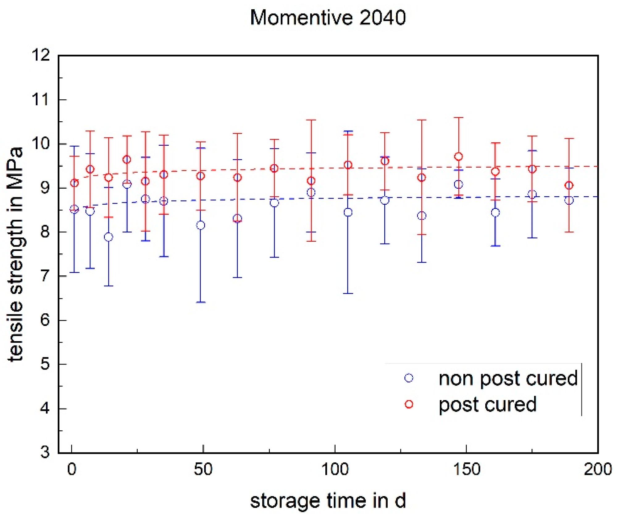
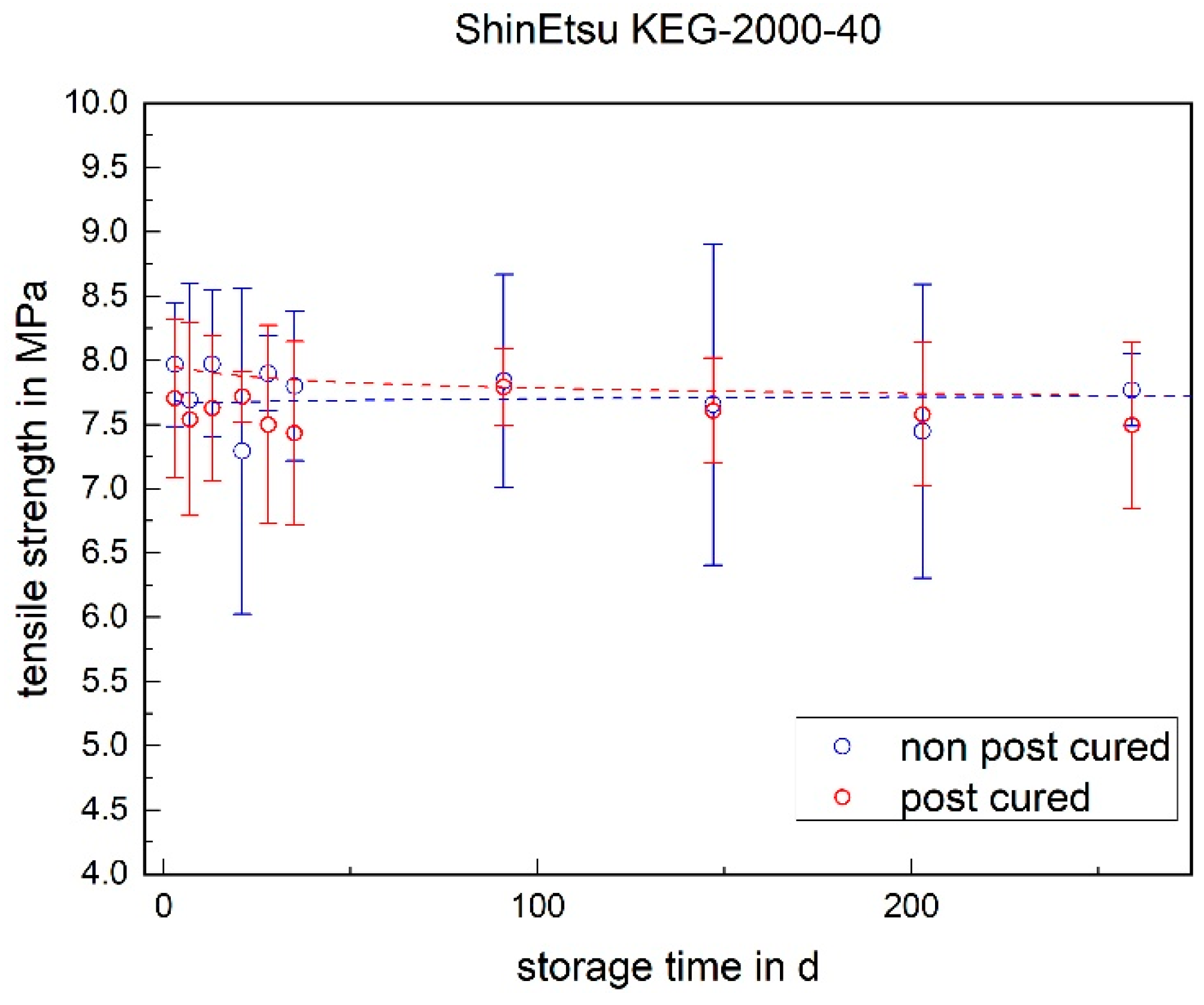
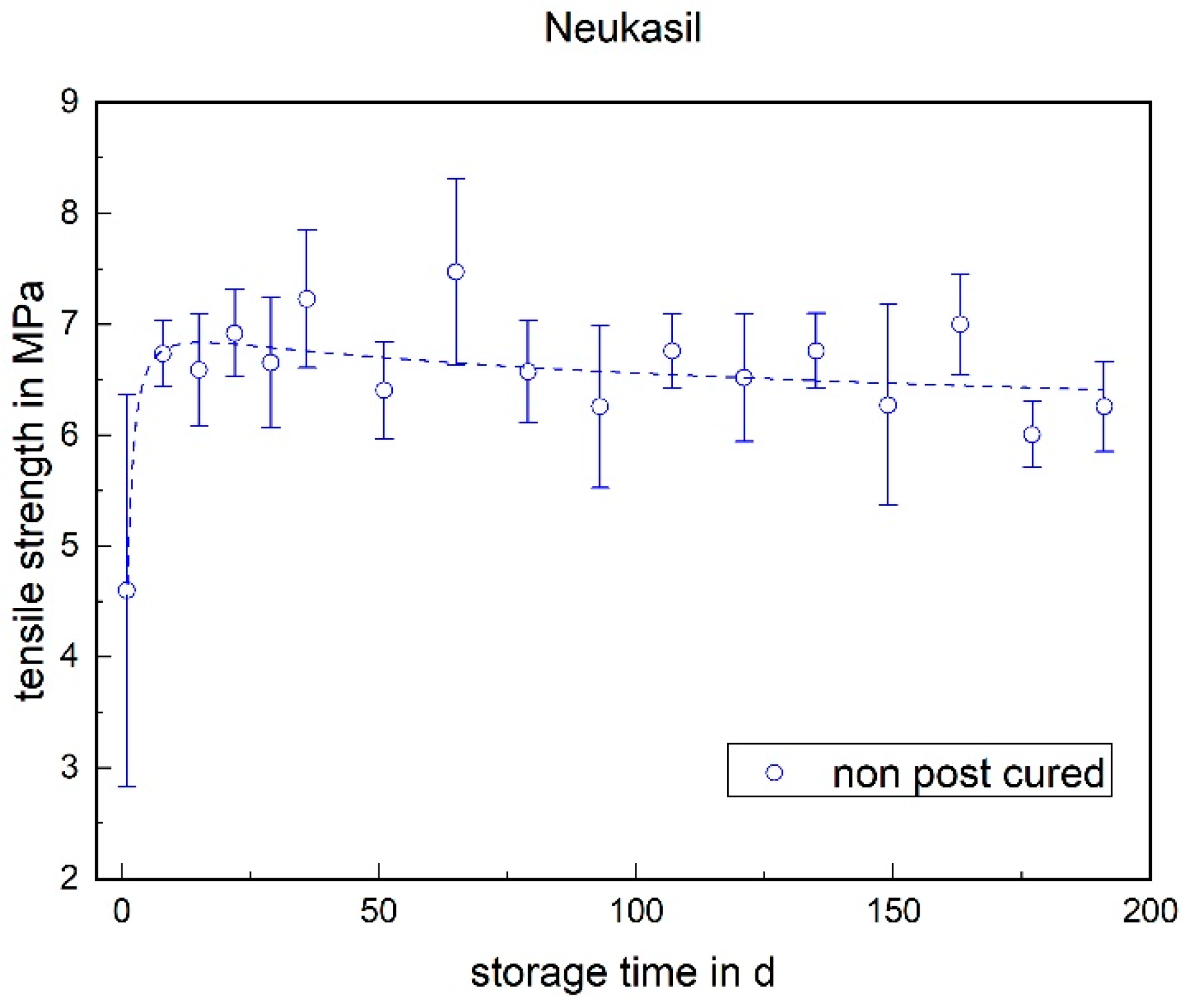
3.1.1. Tensile Strength
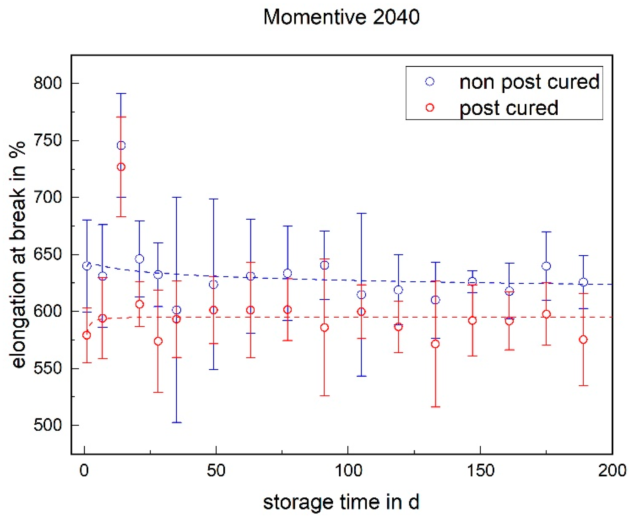
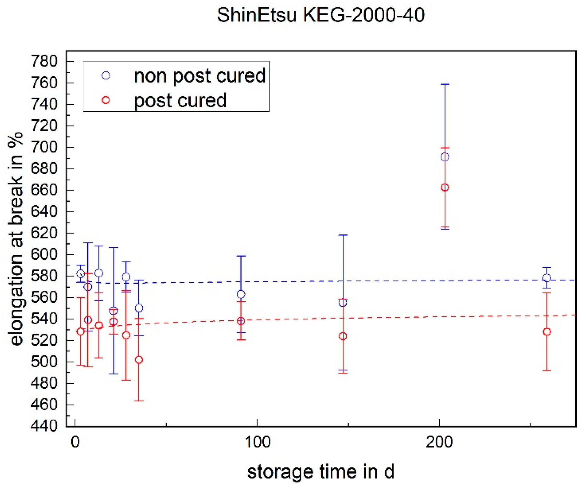
3.1.2. Elongation at Break
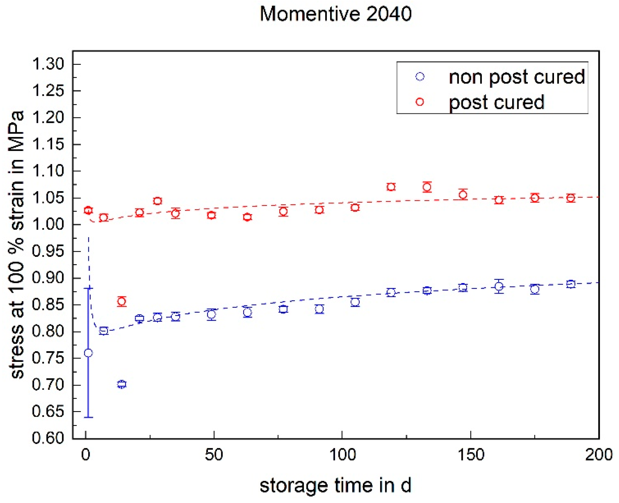
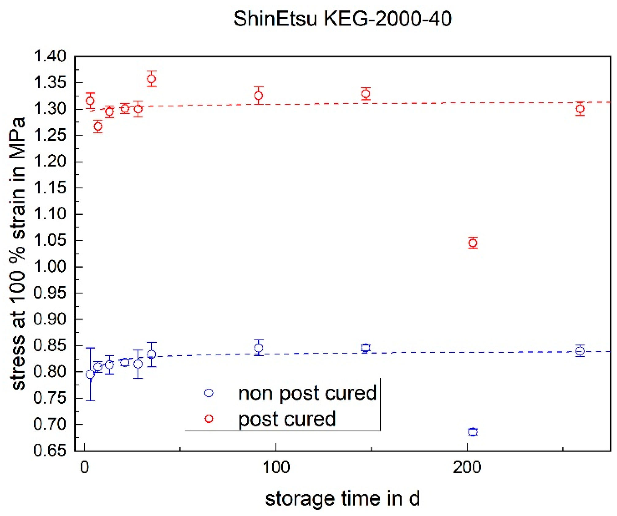
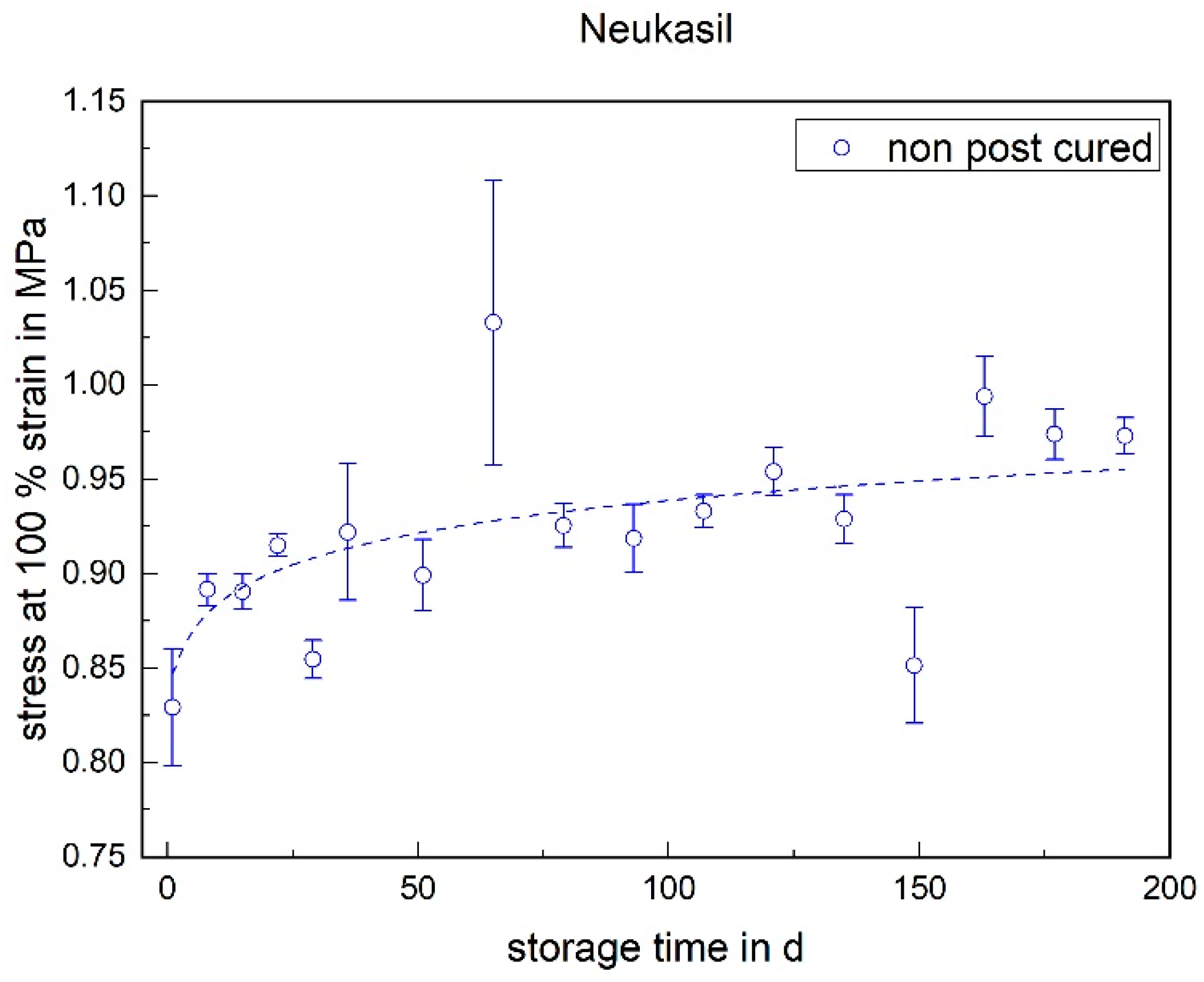
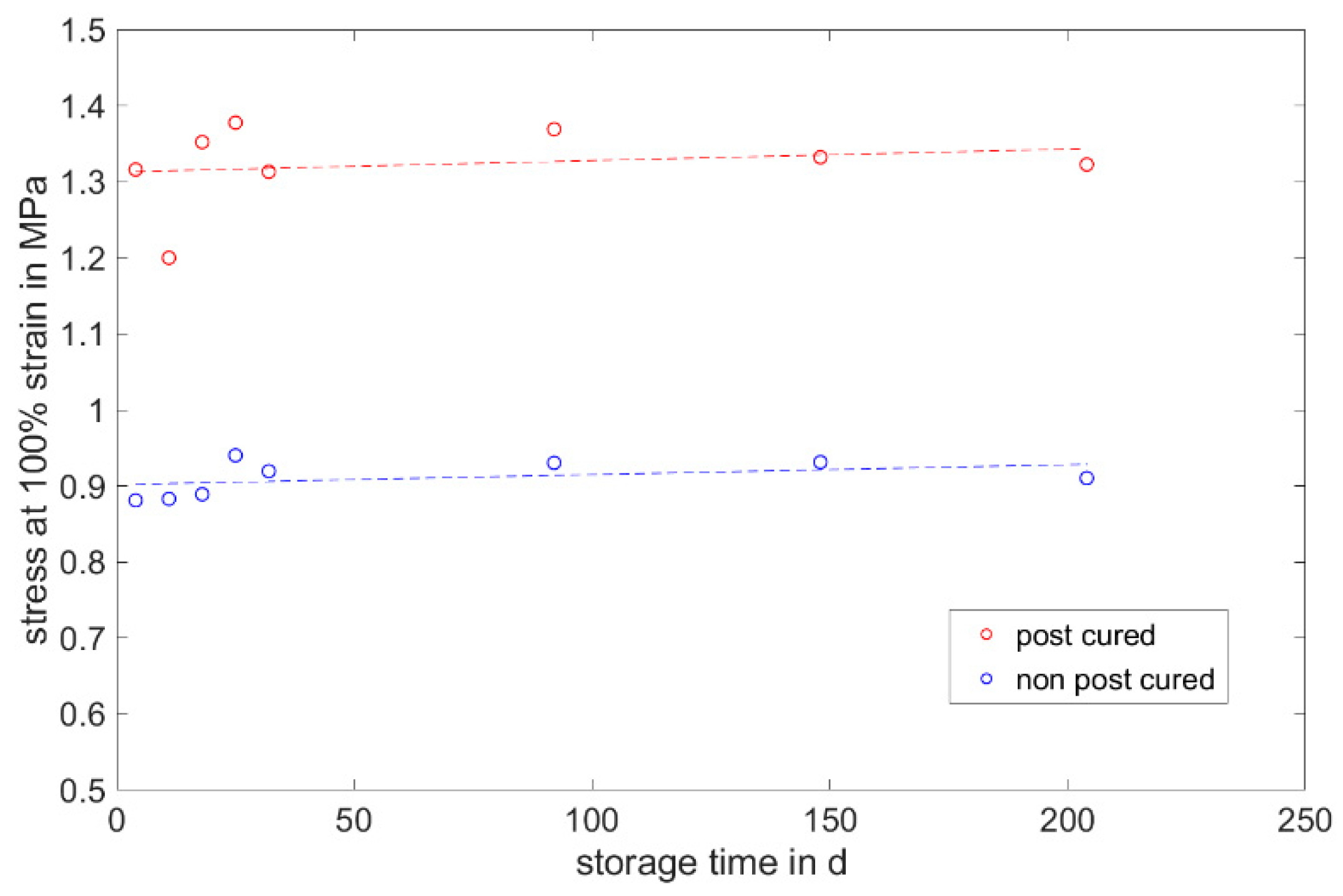
3.1.3. Stress at 100% Strain
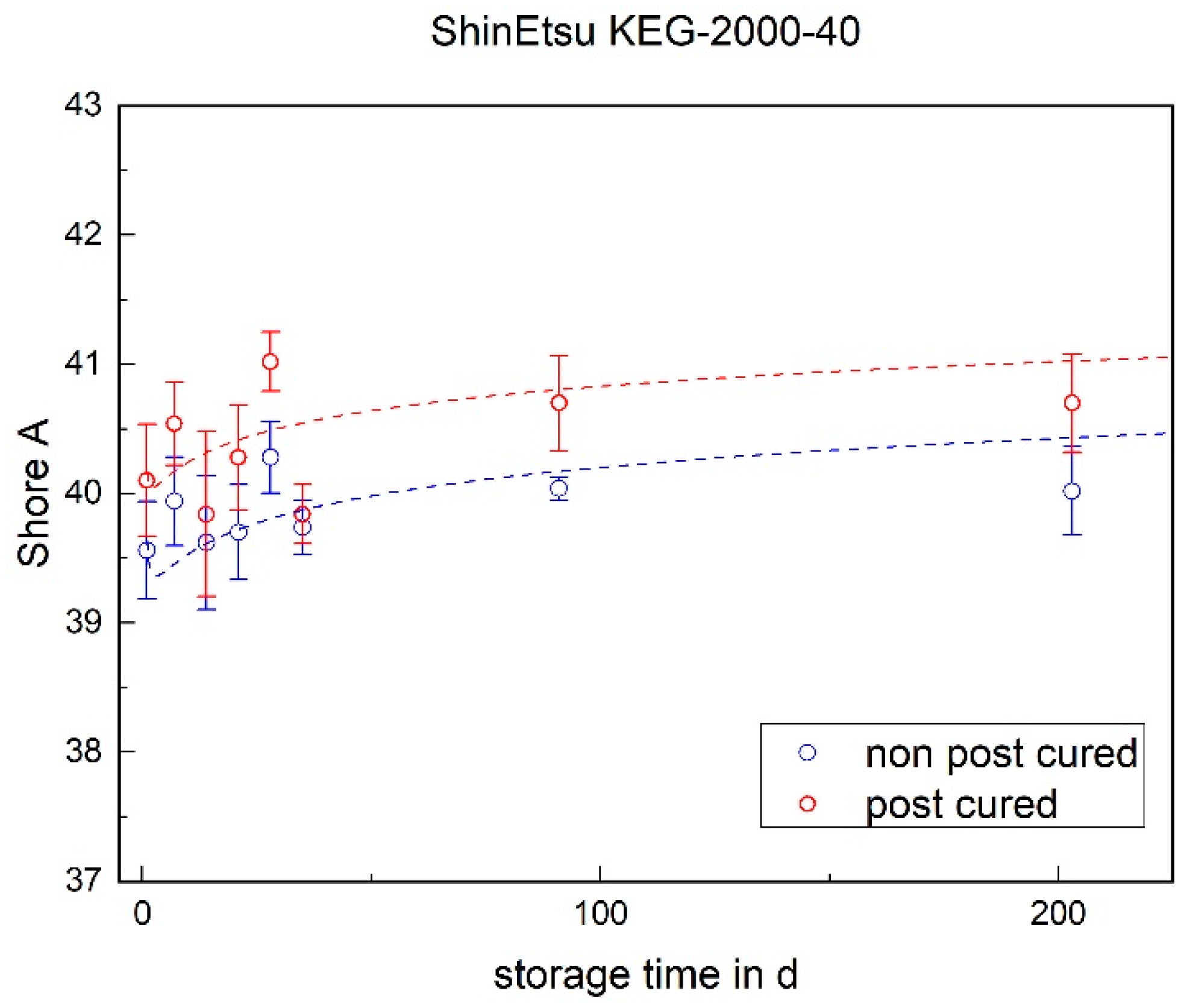
3.2. Shore A Hardness
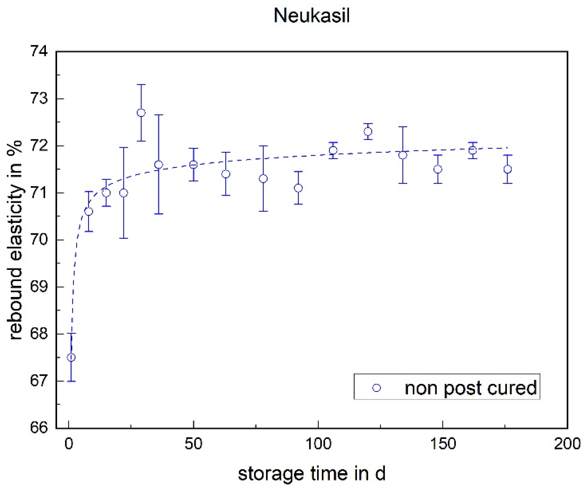
3.3. Rebound Elasticity
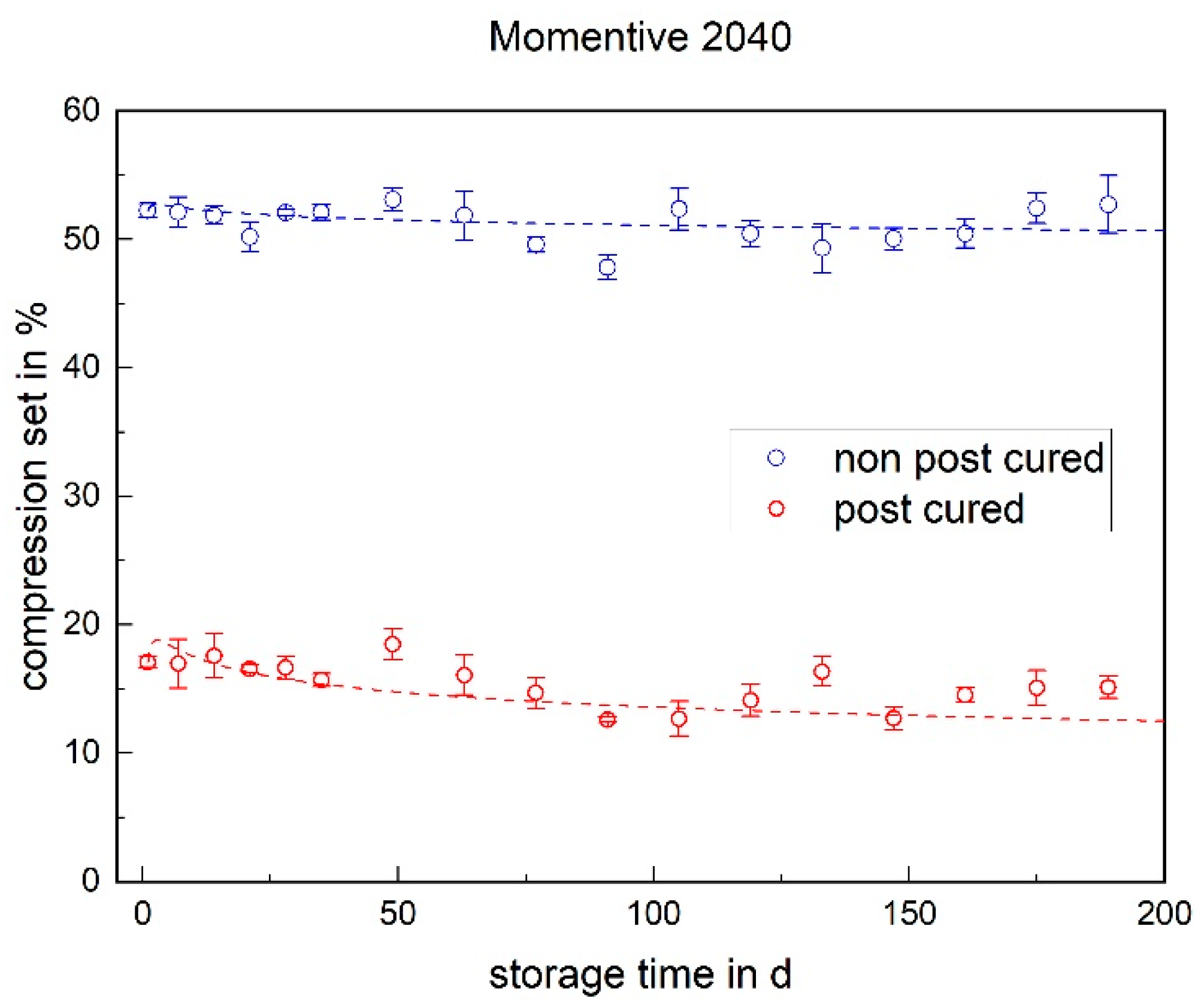
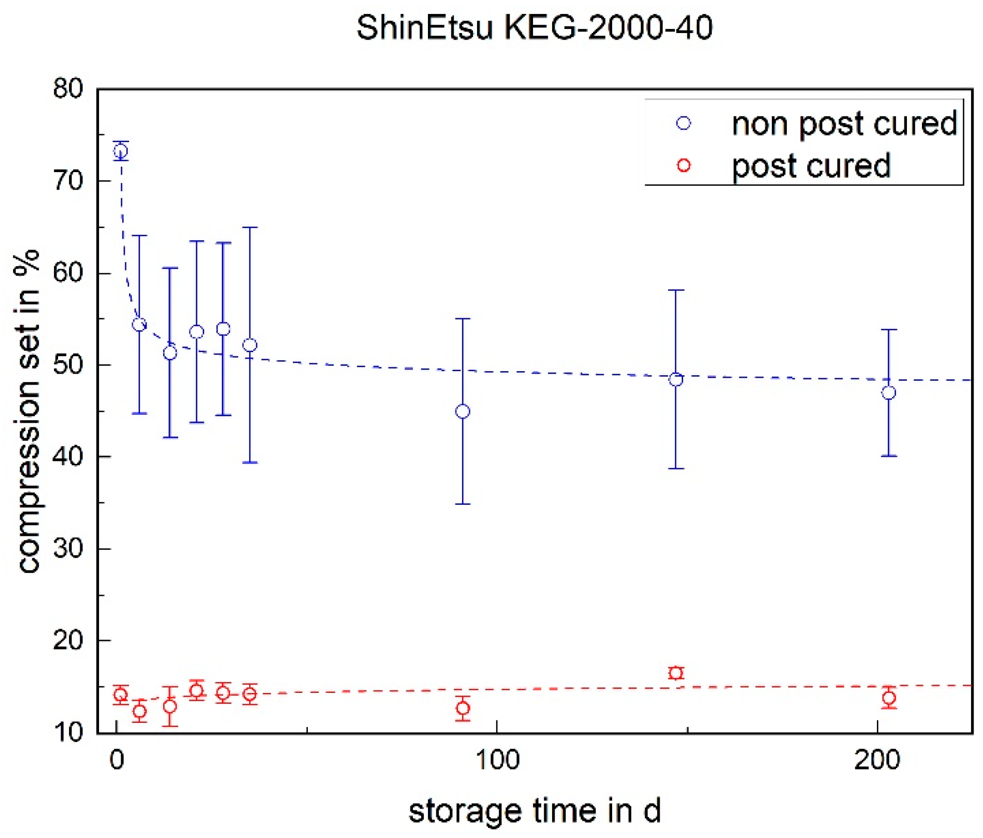
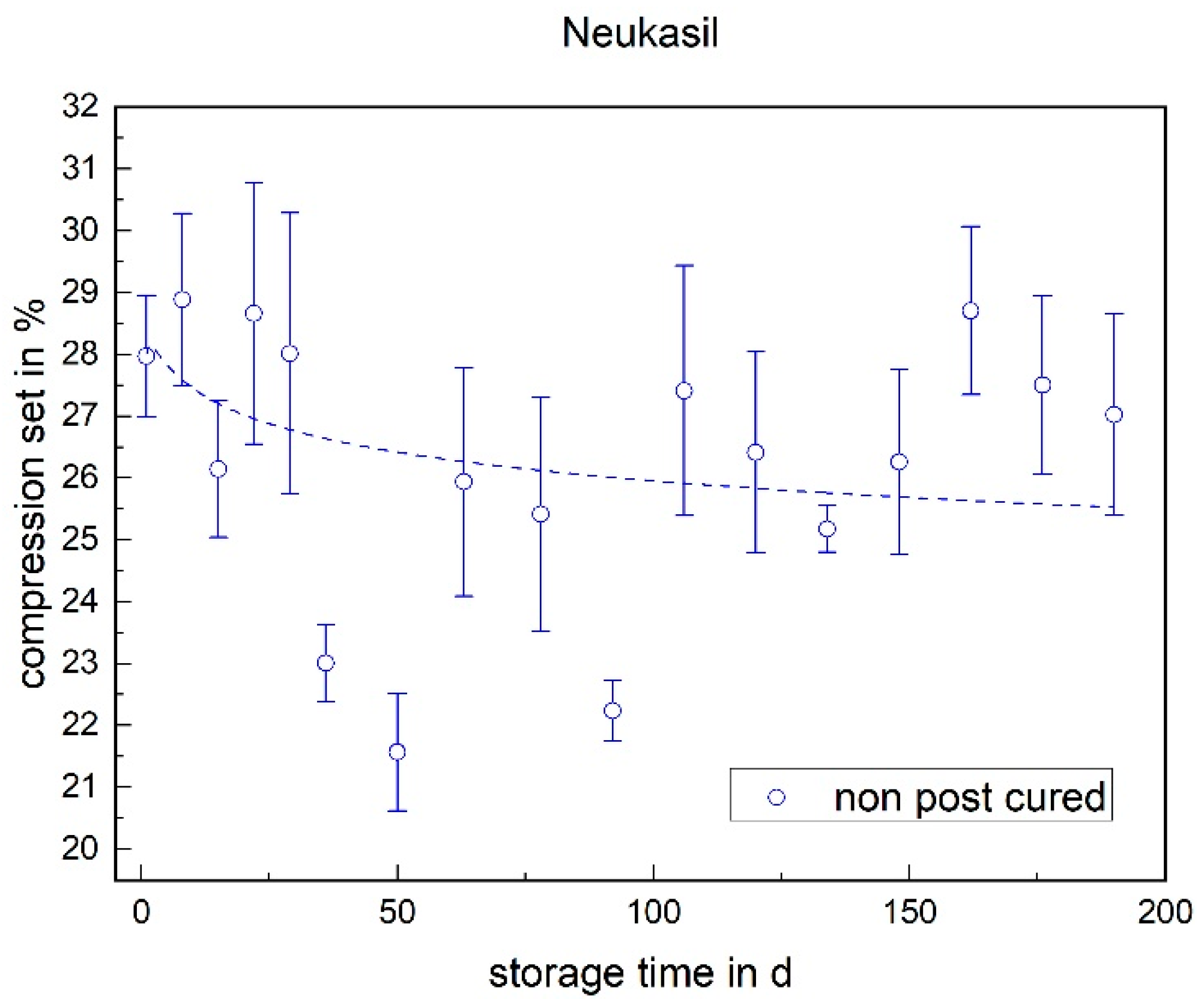
3.4. Compression Set
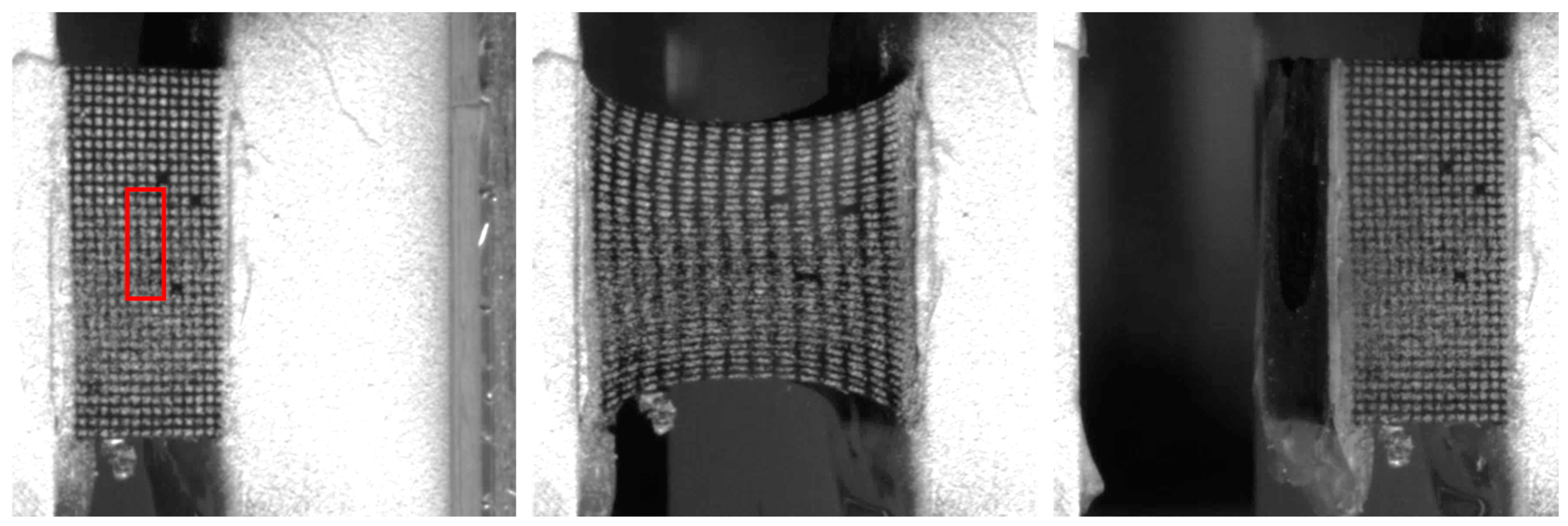
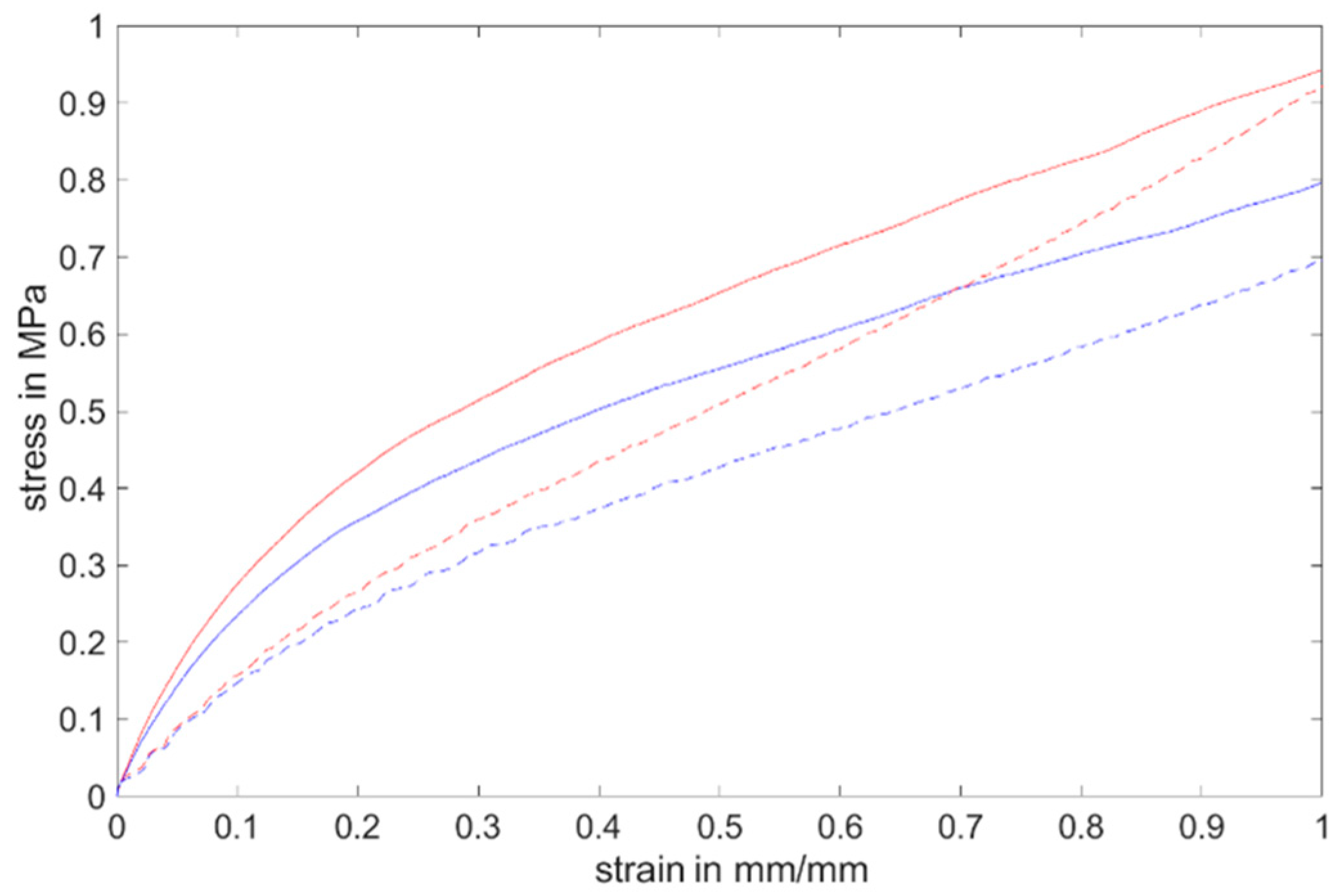
3.5. H-Tensile Test
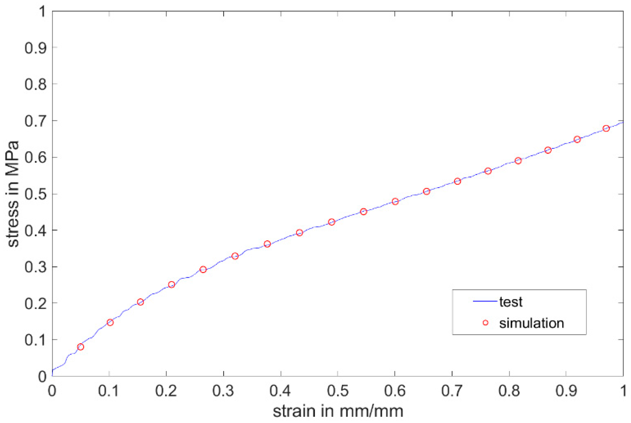
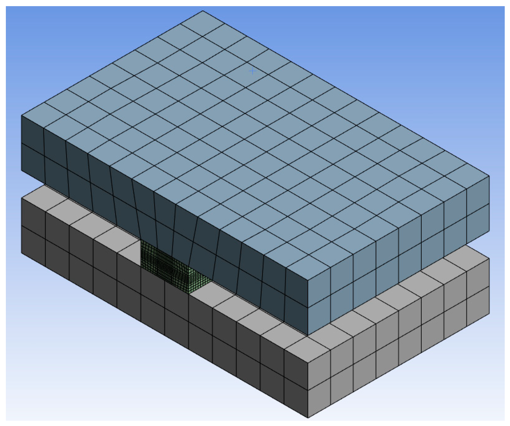
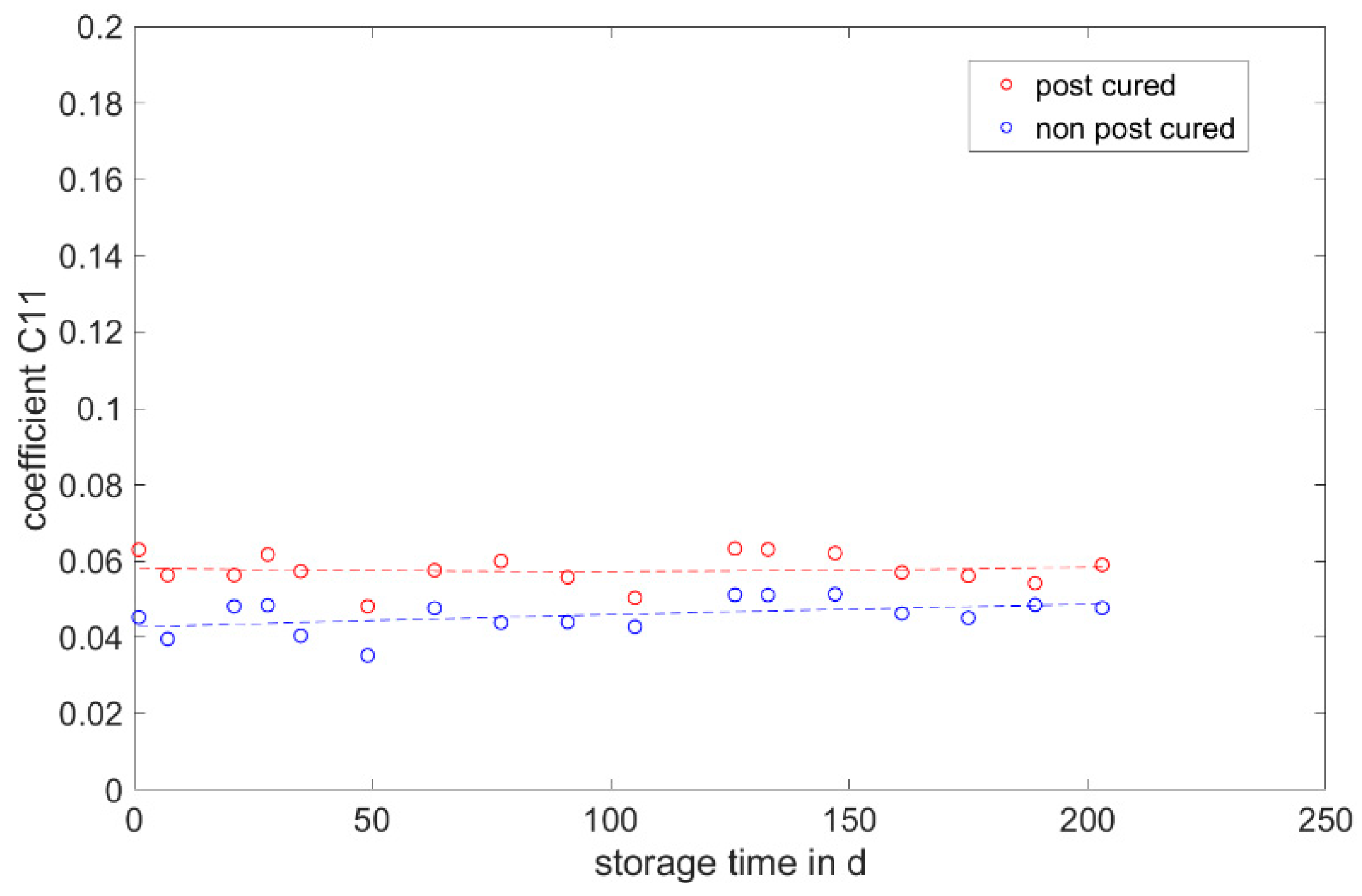
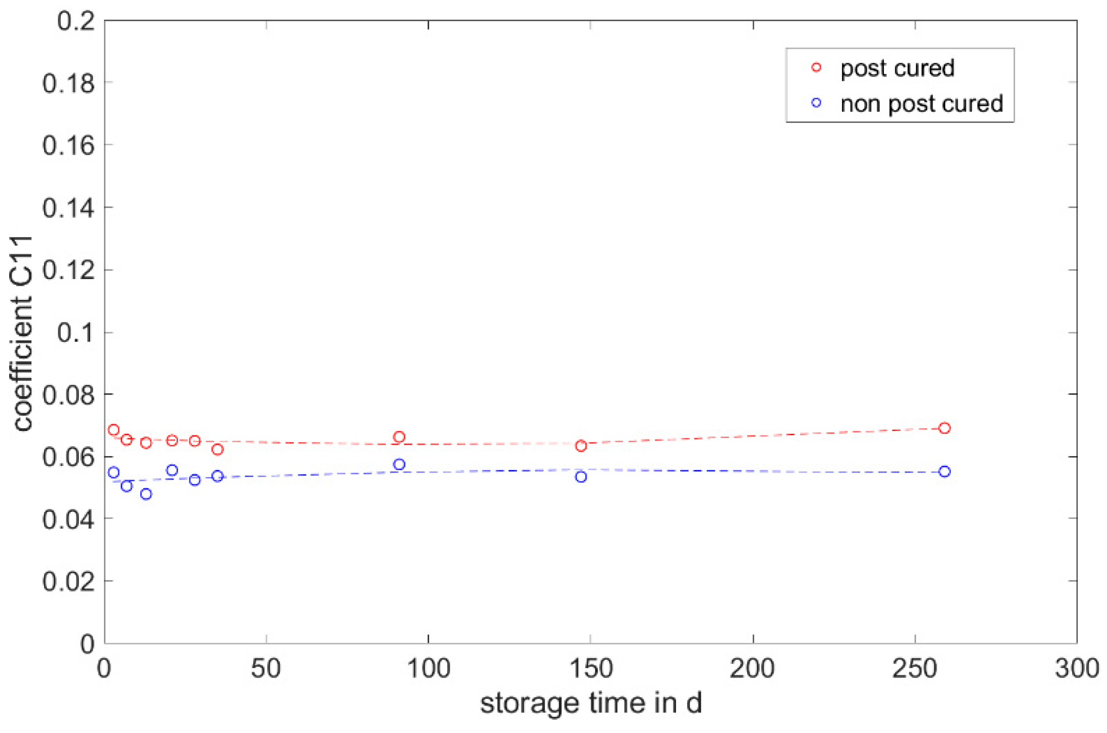
3.6. Simulation
4. Discussion
Author Contributions
Funding
Institutional Review Board Statement
Informed Consent Statement
Data Availability Statement
Conflicts of Interest
References
- Rieg, F.; Hackenschmidt, R.; Alber-Laukant, B. Finite Elemente Analyse für Ingenieure, 4th ed.; Carl Hanser Verlag: München, Germany, 2012. [Google Scholar]
- Hass, W. Kennwertermittlung für FEM-Simulation; Vorlesungsumdruck; University of Stuttgart: Stuttgart, Germany, 2012. [Google Scholar]
- Stommel, M.; Stojek, M.; Korte, W. FEM zur Berechnung von Kunststoff- und Elastomerbauteilen; Carl Hanser Verlag: München, Germany, 2011. [Google Scholar]
- Obermann, P. Berechnungsmethodik zur Beurteilung von Mechatronischen Bauteilen unter Großen Temperaturschwankungen. Ph.D. Thesis, Kassel University, Kassel, Germany, 2017. [Google Scholar]
- Mullins, L. Softening of Rubber by Deformation. Rubber Chem. Technol. 1969, 42, 339–362. [Google Scholar] [CrossRef]
- Miehe, C. Discontinuous and continuous damage evolution in Ogden-type large-strain elastic materials. Eur. J. Mech. A Solids 1995, 14, 697. [Google Scholar]
- Plagge, J.; Klüppel, M. A physically based model of stress softening and hysteresis of filled rubber including rate- and temperature dependency. Int. J. Plast. 2017, 89, 173–196. [Google Scholar] [CrossRef]
- Lorenz, H.; Klüppel, M.; Heinrich, G. Microstructure-based modelling and FE implementation of filler-induced stress softening and hysteresis of reinforced rubbers. ZAMM—J. Appl. Math. Mech. 2012, 92, 608–631. [Google Scholar] [CrossRef]
- Nosper. Mechatronische Anwendungen im KFZ. Vorlesungsumdruck. 2015. Available online: https://silo.tips/download/beispiel-eines-mechatronischen-systems-im-kraftfahrzeugbau (accessed on 19 June 2024).
- Ehrenstein, G.W.; Pongratz, S. Beständigkeit von Kunststoffen; Carl Hanser Verlag: München, Germany, 2007. [Google Scholar]
- Oldfield, D.; Symes, T. Long term natural ageing of silicone elastomers. Polym. Test. 1996, 15, 115–128. [Google Scholar] [CrossRef]
- Wang, Q.; Liang, X.; Yan, Z.; Bao, W.; Jinag, T. The Influence of heat aging on different kinds of silicon rubber material. In Proceedings of the 12th IEEE International Conference on the Properties and Applications of Dielectric Materials, Xi’an, China, 20–24 May 2018. [Google Scholar]
- Brown, R.P.; Soulagnet, G. Microhardness profiles on aged rubber compounds. Polym. Test. 2001, 20, 295–303. [Google Scholar] [CrossRef]
- Wu, J.; Niu, K.; Su, B.; Wang, Y. Effect of combined UV thermal and hydrolytic aging on micro-contact properties of silicone elastomer. Polym. Degrad. Stab. 2018, 151, 126–135. [Google Scholar] [CrossRef]
- Zhang, L.X.; He, S.Y.; Xu, Z.; Wei, Q. Damage effects and mechanisms of proton irradiation on methyl silicone rubber. Mater. Chem. Phys. 2004, 83, 255–259. [Google Scholar] [CrossRef]
- Stevenson, I.; David, L.; Gauthier, C.; Arambourg, L.; Davenas, J.; Vigier, G. Influence of SiO2 fillers on the irradiation ageing of silicone rubbers. Polymer 2001, 42, 9287–9292. [Google Scholar] [CrossRef]
- Keshavaraj, R.; Tock, R.W. Modeling of Changes in Crosslinking for Structural Sili-cone Sealants Subjected to Moisture and Sunlight. Polym.-Plast. Technol. Eng. 1994, 33, 537–550. [Google Scholar] [CrossRef]
- Keshavaraj, R.; Tock, R.W. The effect of length in the test section on the mechanical performance of silicone sealants used in structural glazing. J. Mater. Sci. Lett. 1993, 12, 1627–1628. [Google Scholar] [CrossRef]
- Keshavaraj, R.; Tock, R.W. Oxidative effects of ozone on the aging of structural silicone elastomers. Adv. Polym. Technol. 1994, 13, 149–156. [Google Scholar] [CrossRef]
- Keshavaraj, R.; Tock, R.W. Changes in Crosslink Density of Structural Silicone Seal-ants Due to Ozone and Moisture. Polym.-Plast. Technol. Eng. 1994, 33, 397–417. [Google Scholar] [CrossRef]
- Wu, J.; Dong, J.; Wang, Y.; Gond, B.K. Thermal oxidation ageing effects on silicone rubber sealing performance. Polym. Degrad. Stab. 2017, 135, 43–53. [Google Scholar] [CrossRef]
- Cui, T.; Chao, Y.J.; Chen, X.M.; van Zee, J.W. Effect of water on life prediction of liquid silicone rubber seals in polymer electrolyte membrane fuel cell. J. Power Sources 2011, 196, 9536–9543. [Google Scholar] [CrossRef]
- Cui, T.; Lin, C.-W.; Chien, C.H.; Chao, Y.J.; van Zee, J.W. Service life estimation of liquid silicone rubber seals in polymer electrolyte membrane fuel cell environment. J. Power Sources 2011, 196, 1216–1221. [Google Scholar] [CrossRef]
- Ghanbari-Siahkali, A.; Mitra, S.; Kingshott, P.; Almdal, K.; Bloch, C.; Rehmeier, H.K. Investigation of the hydrothermal stability of cross-linked liquid silicone rubber (LSR). Polym. Degrad. Stab. 2005, 90, 471–480. [Google Scholar] [CrossRef]
- Feng, J.; Zhang, Q.; Tu, Z.; Tu, W.; Wan, Z.; Pan, M.; Zhang, H. Degradation of silicone rubbers with different hardness in various aqueous solutions. Polym. Degrad. Stab. 2014, 109, 122–128. [Google Scholar] [CrossRef]
- Li, G.; Tan, J.; Gong, J. Chemical aging of the silicone rubber in a simulated and three accelerated proton exchange membrane fuel cell environments. J. Power Sources 2012, 217, 175–183. [Google Scholar] [CrossRef]
- Verma, A.R.; Reddy, B.S. Accelerated aging studies of silicon-rubber based polymeric insulators used for HV transmission lines. Polym. Test. 2017, 62, 124–131. [Google Scholar] [CrossRef]
- Weltschev, M.; Heming, F.; Haufe, M.; Heyer, M. The influence of the age of biodiesel and heating oil with 10% biodiesel on the resistance of sealing materials at different temperatures. Mater. Werkst. 2017, 48, 837–845. [Google Scholar] [CrossRef]
- Zakaria, S.; Yu, L.; Kofod, G.; Skov, A.L. The influence of static pre-stretching on the mechanical ageing of filled silicone rubbers for dielectric elastomer applications. Mater. Today Commun. 2015, 4, 204–213. [Google Scholar] [CrossRef]
- Chen, C.; Jia, C.; Wang, X.; Lu, H.; Guan, Z. Micro Characterization and Degradation Mechanism of Liquid Silicone Rubber Used for External Insulation. IEEE Trans. Dielectr. Electr. Insul. 2015, 22, 313–321. [Google Scholar] [CrossRef]
- Gubanski, S. Outdoor Polymeric Insulators: Role of Corona in Performance of Silicone Rubber Housings. In Proceedings of the Annual Report Conference on Electrical Insulation and Dielectric Phenomena, Ann Arbor, MI, USA, 18–21 October 2015. [Google Scholar]
- Kaneko, T.; Ito, S.; Minakawa, T.; Hirai, N.; Ohki, Y. Degradation mechanisms of silicone rubber under different aging conditions. Polym. Degrad. Stab. 2019, 168, 108936. [Google Scholar] [CrossRef]
- Pehlivan-Davis, S.; Clarke, J.; Armour, S. Comparison of Accelerated Aging of Silicone Rubber Gasket Material with Aging in a Fuel Cell Environment. J. Appl. Polym. Sci. 2013, 129, 1446–1454. [Google Scholar] [CrossRef]
- Kashi, S.; Varley, R.; De Souza, M.; Al-Assafi, S.; Di Pietro, A.; de Lavigne, C.; Fox, B. Mechanical, Thermal, and Morphological Behavior of Silicone Rubber during Accelerated Aging. Polym.-Plast. Technol. Eng. 2018, 57, 1687–1696. [Google Scholar] [CrossRef]
- Altropol Kunststoff GmbH (Hg.): Neukasil RTV 230. 2019. Available online: https://www.altropol.de/files/content/DE/produkte/produktgruppen/neukasil-rtv-silikone/additionssysteme/datenblaetter/D_RTV_230.pdf (accessed on 19 June 2024).
- Momentive Performance Materials (Hg.): Silopren LSR 2040. Available online: https://www.momentive.com/en-us/products/tds/silopren-lsr-2040?productId=d6535c04-8888-46f1-8f42-ece56f0ca247 (accessed on 19 June 2024).
- Shin-Etsu Chemical (Hg.): KEG-2000-40. Available online: https://www.shinetsusilicones.com/elastomer.aspx?ID=KEG-2000-40A/B (accessed on 19 June 2024).
- Wacker Chemie AG (Hg.): Elastosil Color Paste Fl Black RAL 9005 F. 2023. Available online: https://www.wacker.com/h/de-de/siliconkautschuk/additive-fuer-siliconkautschuk/elastosil-color-paste-fl-black-ral-9005-f/p/000005178 (accessed on 19 June 2024).
- DIN 53504:2017-03 (2017); Testing of Rubber—Determination of Tensile Strength at Break, Tensile Stress at Yield, Elongation at Break and Stress Values in a Tensile Test. Beuth-Verlag: Berlin, Germany, 2017.
- DIN ISO 815-1:2016-09 (2016); Rubber, Vulcanized or Thermoplastic—Determination of Compression Set—Part 1: At Ambient or Elevated Temperatures. Beuth-Verlag: Berlin, Germany, 2016.
- DIN EN ISO 868:2003-10 (2003); Plastics and Ebonite—Determination of Indentation Hardness by Means of a Durometer (Shore Hardness). Beuth-Verlag: Berlin, Germany, 2003.
- DIN 53512: 2000-04 (2000); Testing of Rubber—Determination of Rebound Resilience (Schob Pendulum). Beuth-Verlag: Berlin, Germany, 2000.
- Kautschukelastizität. Available online: https://www.spektrum.de/lexikon/physik/kautschukelastizitaet/7844 (accessed on 19 June 2024).
- Mooney, M. A theory of large elastic deformation. J. Appl. Phys. 1940, 11, 582–592. [Google Scholar] [CrossRef]
- Ni, X.; Fister, M.; Spieker, C.; Marl, S.; Heim, P. Messung des Kompressionsmoduls von Silikon-Werkstoffen mittels eines entwickelten volumetrischen Kompressionsversuchs. Kautsch. Gummi Kunststoffe 2023, 76, 39–43. [Google Scholar]
- Phothiphatcha, J.; Tumrong, P. Determination of material parameters of PDMS material models by MATLAB. Eng. J. 2021, 25, 11–28. [Google Scholar] [CrossRef]


| Material | Geometry | Standard | Mold Temperature in °C | Vulcanization Time in s | Injection Volume in cm3 |
|---|---|---|---|---|---|
| Momentive Silopren LSR 2040 | Tensile bar S2 | DIN 53504 | 180 | 8 | 3 |
| cylindrical disk type A | DIN ISO 815-1 | 180 | 105 | 10.5 | |
| cylindrical disk type B | DIN ISO 815-1 | 180 | 25 | 2.25 | |
| H sample | - | 130 | 58 | 3 | |
| ShinEtsu KEG-2000-40 | Tensile bar S2 | DIN 53504 | 180 | 8 | 3 |
| cylindrical disk type A | DIN ISO 815-1 | 180 | 110 | 9.6 | |
| cylindrical disk type B | DIN ISO 815-1 | 180 | 35 | 2.15 | |
| H sample | - | 130 | 58 | 3.35 |
| Program Level | Revolutions in rpm | Time in min | Pressure in mbar |
|---|---|---|---|
| 1 | 1000 | 00:15 | 1000 |
| 2 | 800 | 01:00 | 1000 |
| 3 | 800 | 01:00 | 500 |
Disclaimer/Publisher’s Note: The statements, opinions and data contained in all publications are solely those of the individual author(s) and contributor(s) and not of MDPI and/or the editor(s). MDPI and/or the editor(s) disclaim responsibility for any injury to people or property resulting from any ideas, methods, instructions or products referred to in the content. |
© 2024 by the authors. Licensee MDPI, Basel, Switzerland. This article is an open access article distributed under the terms and conditions of the Creative Commons Attribution (CC BY) license (https://creativecommons.org/licenses/by/4.0/).
Share and Cite
Marl, S.; Ni, X.; Hornig, T.; Spieker, C.; Giesen, R.-U.; Heim, H.-P.; Fister, M. Correlations between the Aging Behavior and Finite Element Method Simulation of Three Silicone Elastomers. Materials 2024, 17, 3961. https://doi.org/10.3390/ma17163961
Marl S, Ni X, Hornig T, Spieker C, Giesen R-U, Heim H-P, Fister M. Correlations between the Aging Behavior and Finite Element Method Simulation of Three Silicone Elastomers. Materials. 2024; 17(16):3961. https://doi.org/10.3390/ma17163961
Chicago/Turabian StyleMarl, Svenja, Xiaofei Ni, Tobias Hornig, Christian Spieker, Ralf-Urs Giesen, Hans-Peter Heim, and Michael Fister. 2024. "Correlations between the Aging Behavior and Finite Element Method Simulation of Three Silicone Elastomers" Materials 17, no. 16: 3961. https://doi.org/10.3390/ma17163961