
Simultaneous Necking and Barreling Deformation Behaviors in Bending of Single-Crystal Gold Micro-Cantilever
 , ,
, ,  and
and 
Abstract
:1. Introduction
2. Materials and Methods
2.1. Materials
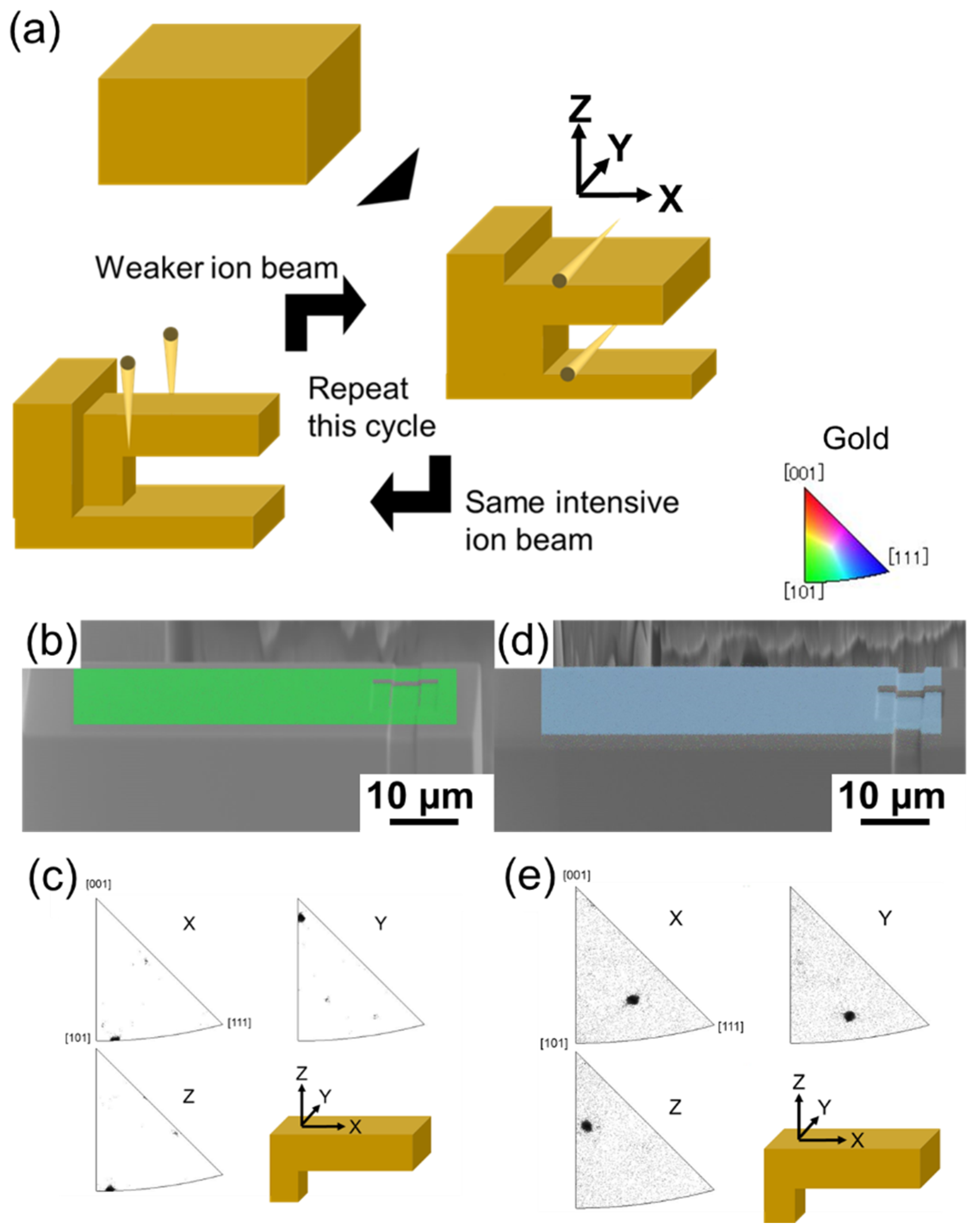
2.2. Methods
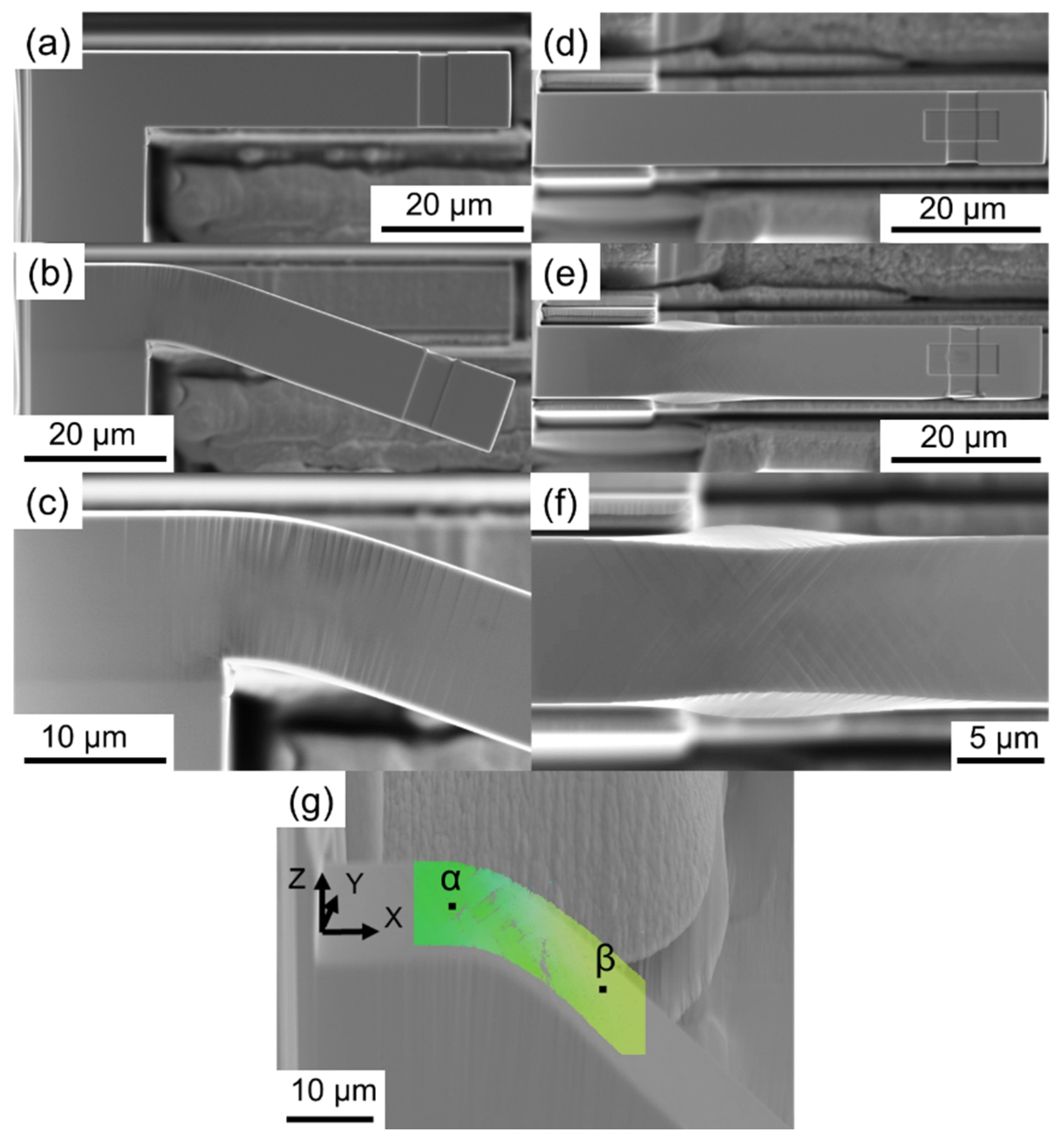
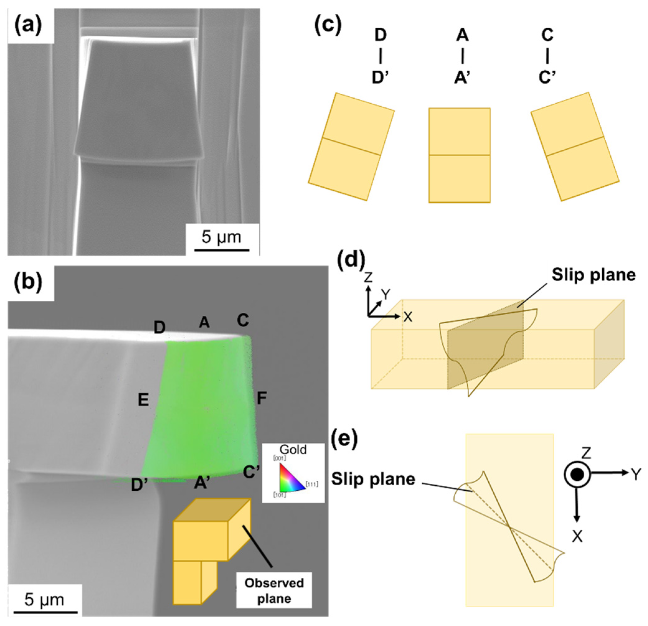
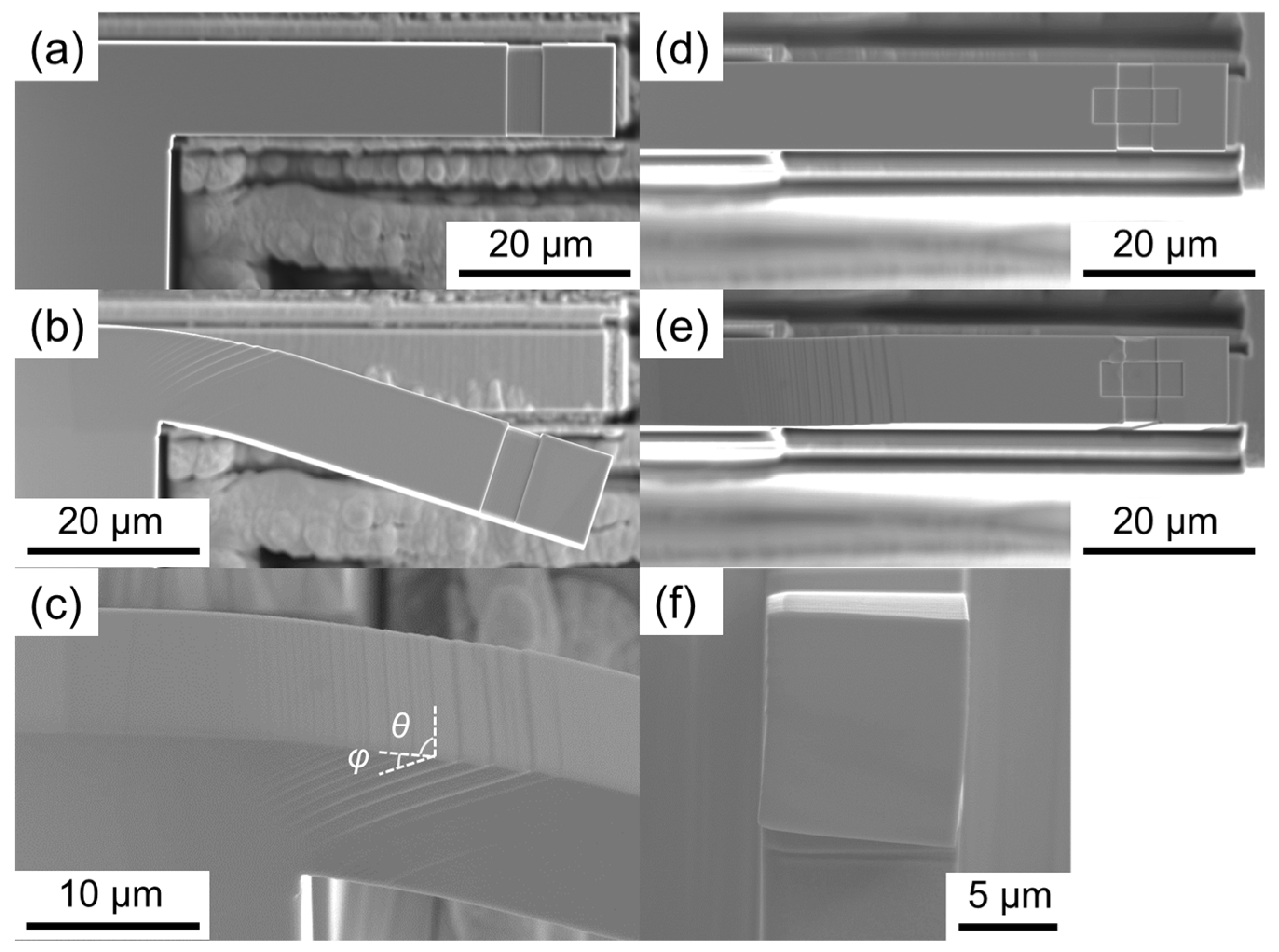
3. Results and Discussion
4. Conclusions
Author Contributions
Funding
Institutional Review Board Statement
Informed Consent Statement
Data Availability Statement
Conflicts of Interest
References
- Goodman, P. Current and future uses of gold in electronics. Gold Bull. 2002, 35, 21–26. [Google Scholar] [CrossRef]
- Takakura, M.; Fukuda, K.; Yokoda, T.; Inoue, D.; Hashizume, D.; Umezu, S.; Someya, T. Direct gold bonding for flexible integrated electronics. Sci. Adv. 2021, 7, eabl6228. [Google Scholar] [CrossRef] [PubMed]
- Gong, S.; Schwalb, W.; Wang, Y.; Chen, Y.; Tang, Y.; Si, J.; Shirinzadeh, B.; Cheng, W. A wearable and highly sensitive pressure sensor with ultrathin gold nanowires. Nat. Commun. 2014, 5, 3132. [Google Scholar] [CrossRef] [PubMed]
- Konishi, T.; Yamane, D.; Matsushima, T.; Masu, K.; Toshiyoshi, H. A capacitive CMOS–MEMS sensor designed by multi-physics simulation for integrated CMOS–MEMS technology. Jpn. J. Appl. Phys. 2014, 53, 04EE15. [Google Scholar] [CrossRef]
- Yamane, D.; Matsushima, T.; Machida, K.; Toshiyoshi, H.; Masu, K. Design of sub-1g microelectromechanical systems accelerometers. Appl. Phys. Lett. 2014, 104, 074102. [Google Scholar] [CrossRef]
- Jiang, L.; Wang, L.; Huang, X.; Huang, Z.; Huang, M. Implementation of Highly Reliable Contacts for RF MEMS Switches. Micromachines 2024, 15, 155. [Google Scholar] [CrossRef]
- Gill, W.A.; Howard, I.; Mazhar, I.; McKee, K. A Review of MEMS Vibrating Gyroscopes and Their Reliability Issues in Harsh Environments. Sensors 2022, 22, 7405. [Google Scholar] [CrossRef] [PubMed]
- Zhang, Y.; Sun, J.; Liu, H.; Liu, Z. Modeling and Measurement of Thermal—Mechanical-Stress-Creep Effect for RF MEMS Switch Up to 200 °C. Micromachines 2022, 13, 166. [Google Scholar] [CrossRef] [PubMed]
- Deng, C.; Sansoz, F. Near-ideal strength in gold nanowires achieved through microstructural design. ACS Nano 2009, 3, 3001–3008. [Google Scholar] [CrossRef]
- Youssef, K.M.; Scattergood, R.O.; Murty, K.L.; Horton, J.A.; Koch, C.C. Ultrahigh strength and high ductility of bulk nanocrystalline copper. Appl. Phys. Lett. 2005, 87, 091904. [Google Scholar] [CrossRef]
- Zhang, Y.; Ding, K.; Stangebye, S.; Chen, D.; Kacher, J.; Pierron, O.; Zhu, T. Atomistic modeling of surface and grain boundary dislocation nucleation in FCC metals. Acta Mater. 2022, 237, 118155. [Google Scholar] [CrossRef]
- Cao, A.J.; Wei, Y.G.; Mao, S.X. Deformation mechanisms of face-centered-cubic metal nanowires with twin boundaries. Appl. Phys. Lett. 2007, 90, 151909. [Google Scholar] [CrossRef]
- Yoshiba, M.; Chen, C.Y.; Chang, T.F.M.; Nagoshi, T.; Yamane, D.; Machida, K.; Masu, K.; Sone, M. Deformation behavior of electroplated gold composed of nano-columnar grains embedded in micro-columnar textures. Mater. Lett. 2017, 202, 82–85. [Google Scholar] [CrossRef]
- Jiang, M.; Fan, Z.; Kruch, S.; Devincre, B. Grain size effect of FCC polycrystal: A new CPFEM approach based on surface geometrically necessary dislocations. Int. J. Plast. 2022, 150, 103181. [Google Scholar] [CrossRef]
- Solhjoo, S. ACTAS: A New Framework for Mechanical and Frictional Characterization in Axisymmetric Compression Test. Materials 2023, 16, 441. [Google Scholar] [CrossRef] [PubMed]
- Mirone, G.; Barbagallo, R.; Bua, G.; De Caro, D.; Ferrea, M.; Tedesco, M.M. A Simple Procedure for the Post-Necking Stress-Strain Curves of Anisotropic Sheet Metals. Metals 2023, 13, 1156. [Google Scholar] [CrossRef]
- Greer, J.R.; Oliver, W.C.; Nix, W.D. Size dependence of mechanical properties of gold at the micron scale in the absence of strain gradients. Acta Mater. 2005, 53, 1821–1830. [Google Scholar] [CrossRef]
- Greer, J.R.; De Hosson, J.T.M. Plasticity in small-sized metallic systems: Intrinsic versus extrinsic size effect. Prog. Mater. Sci. 2011, 56, 654–724. [Google Scholar] [CrossRef]
- Zhang, W.; Li, Z.; Dang, R.; Tran, T.T.; Gallivan, R.A.; Gao, H.; Greer, J.R. Suppressed Size Effect in Nanopillars with Hierarchical Microstructures Enabled by Nanoscale Additive Manufacturing. Nano Lett. 2023, 23, 8162–8170. [Google Scholar] [CrossRef]
- Maurizi, M.; Edwards, B.W.; Gao, C.; Greer, J.R.; Berto, F. Fracture resistance of 3D nano-architected lattice materials. Extrem. Mech. Lett. 2022, 56, 101883. [Google Scholar] [CrossRef]
- Stölken, J.S.; Evans, A.G. A microbend test method for measuring the plasticity length scale. Acta Mater. 1998, 46, 5109–5115. [Google Scholar] [CrossRef]
- Kiener, D.; Grosinger, W.; Dehm, G.; Pippan, R. A further step towards an understanding of size-dependent crystal plasticity: In situ tension experiments of miniaturized single-crystal copper samples. Acta Mater. 2008, 56, 580–592. [Google Scholar] [CrossRef]
- Fritz, R.; Maier-Kiener, V.; Lutz, D.; Kiener, D. Interplay between sample size and grain size: Single crystalline vs. ultrafine-grained chromium micropillars. Mater. Sci. Eng. A 2016, 674, 626–633. [Google Scholar] [CrossRef]
- Kiener, D.; Misra, A. Nanomechanical characterization. MRS Bull. 2024, 49, 214–223. [Google Scholar] [CrossRef]
- Schmuck, K.; Burtscher, M.; Alfreider, M.; Wurmshuber, M.; Kiener, D. Micro-Mechanical Fracture Investigations on Grain Size Tailored Tungsten-Copper Nanocomposites. JOM 2024, 76, 2302–2314. [Google Scholar] [CrossRef]
- Teng, F.; Shiau, C.-H.; Sun, C.; O’Brien, R.C.; McMurtrey, M.D. Investigation of Deformation Behavior of Additively Manufactured AISI 316L Stainless Steel with in situ Micro-Compression Testing. Materials 2023, 16, 5980. [Google Scholar] [CrossRef]
- Kihara, Y.; Chang, T.F.M.; Hosoda, H.; Sato, T.; Sone, M. Tensile behavior of micro-sized specimen made of single crystalline nickel. Mater. Lett. 2015, 153, 36–39. [Google Scholar] [CrossRef]
- Singh, M.; Sharma, S.; Muniappan, A.; Pimenov, D.Y.; Wojciechowski, S.; Jha, K.; Dwivedi, S.P.; Li, C.; Królczyk, J.B.; Walczak, D.; et al. In Situ Micro-Observation of Surface Roughness and Fracture Mechanism in Metal Microforming of Thin Copper Sheets with Newly Developed Compact Testing Apparatus. Materials 2022, 15, 1368. [Google Scholar] [CrossRef]
- Suzuki, K.; Chang, T.F.M.; Hashigata, K.; Asano, K.; Chen, C.Y.; Nagoshi, T.; Yamane, D.; Ito, H.; Machida, K.; Masu, K.; et al. Correlation of sample geometry and grain size in micro-bending of electrodeposited polycrystalline gold. Mater. Today Commun. 2023, 35, 106072. [Google Scholar] [CrossRef]
- Guo, S.; Tian, C.; Pan, H.; Tang, X.; Han, L.; Wang, J. Research on the Springback Behavior of 316LN Stainless Steel in Micro-Scale Bending Processes. Materials 2022, 15, 6373. [Google Scholar] [CrossRef] [PubMed]
- Islam, M.T.; Weinberger, C.R.; Thompson, G.B. Rapid microcantilever preparation for conditional fracture toughness evaluation. J. Mater. Res. Technol. 2024, 30, 5444–5454. [Google Scholar] [CrossRef]
- Takashima, K.; Higo, Y.; Sugiura, S.; Shimojo, M. Fatigue crack growth behavior of micro-sized specimens prepared from an electroless plated Ni-P amorphous alloy thin film. Mater. Trans. 2001, 42, 68–73. [Google Scholar] [CrossRef]
- Huang, K.; Sumigawa, T.; Kitamura, T. Experimental evaluation of loading mode effect on plasticity of microscale single-crystal copper. Mater. Sci. Eng. A 2021, 806, 14082. [Google Scholar] [CrossRef]
- Demir, E.; Raabe, D.; Roters, F. The mechanical size effect as a mean-field breakdown phenomenon: Example of microscale single crystal beam bending. Acta Mater. 2010, 58, 1876–1886. [Google Scholar] [CrossRef]
- Velayarce, J.R.; Zamanzade, M.; Abad, O.T.; Motz, C. Influence of single and multiple slip conditions and temperature on the size effect in micro bending. Acta Mater. 2018, 154, 325–333. [Google Scholar] [CrossRef]
- Motz, C.; Schöberl, T.; Pippan, R. Mechanical properties of micro-sized copper bending beams machined by the focused ion beam technique. Acta Mater. 2005, 53, 4269–4279. [Google Scholar] [CrossRef]


| Sample | Thickness (μm) | Width (μm) | Yield Stress (MPa) |
|---|---|---|---|
| A-T5W10 | 5.5 | 9.8 | 237 |
| A-T7.5W10 | 6.9 | 9.7 | 195 |
| A-TW10 | 10.5 | 9.7 | 175 |
| A-T12.5W10 | 12.8 | 9.8 | 159 |
| A-T15W10 | 15.1 | 9.3 | 128 |
| A-T10W5 | 10.0 | 4.7 | 177 |
| A-T10W7.5 | 10.0 | 7.4 | 187 |
| A-T10W12.5 | 10.6 | 12.5 | 177 |
| A-T10W15 | 10.2 | 15.1 | 183 |
| B-TW10 | 10.5 | 10.1 | 77 |
| Slip System | Schmid’s Factor (Absolute Value) |
|---|---|
| ()/[] | 0 |
| ()/[] | 0.408 |
| ()/[] | 0.408 |
| ()/[] | 0 |
| ()/[] | 0.408 |
| ()/[] | 0.408 |
| ()/[] | 0 |
| ()/[] | 0 |
| ()/[] | 0 |
| ()/[] | 0 |
| ()/[] | 0 |
| ()/[] | 0 |
| Slip System | Schmid’s Factor (Absolute Value) |
|---|---|
| ()/[] | 0.17 |
| ()/[] | 0.16 |
| ()/[] | 0.33 |
| ()/[] | 0.004 |
| ()/[] | 0.02 |
| ()/[] | 0.016 |
| ()/[] | 0.35 |
| ()/[] | 0.10 |
| ()/[] | 0.46 |
| ()/[] | 0.17 |
| ()/[] | 0.28 |
| ()/[] | 0.10 |
Disclaimer/Publisher’s Note: The statements, opinions and data contained in all publications are solely those of the individual author(s) and contributor(s) and not of MDPI and/or the editor(s). MDPI and/or the editor(s) disclaim responsibility for any injury to people or property resulting from any ideas, methods, instructions or products referred to in the content. |
© 2024 by the authors. Licensee MDPI, Basel, Switzerland. This article is an open access article distributed under the terms and conditions of the Creative Commons Attribution (CC BY) license (https://creativecommons.org/licenses/by/4.0/).
Share and Cite
Fujita, K.; Suzuki, K.; Asano, K.; Chen, C.-Y.; Kurioka, T.; Machida, K.; Ito, H.; Miyake, Y.; Sone, M.; Chang, T.-F.M. Simultaneous Necking and Barreling Deformation Behaviors in Bending of Single-Crystal Gold Micro-Cantilever. Materials 2024, 17, 4054. https://doi.org/10.3390/ma17164054
Fujita K, Suzuki K, Asano K, Chen C-Y, Kurioka T, Machida K, Ito H, Miyake Y, Sone M, Chang T-FM. Simultaneous Necking and Barreling Deformation Behaviors in Bending of Single-Crystal Gold Micro-Cantilever. Materials. 2024; 17(16):4054. https://doi.org/10.3390/ma17164054
Chicago/Turabian StyleFujita, Kazuya, Kosuke Suzuki, Keisuke Asano, Chun-Yi Chen, Tomoyuki Kurioka, Katsuyuki Machida, Hiroyuki Ito, Yoshihiro Miyake, Masato Sone, and Tso-Fu Mark Chang. 2024. "Simultaneous Necking and Barreling Deformation Behaviors in Bending of Single-Crystal Gold Micro-Cantilever" Materials 17, no. 16: 4054. https://doi.org/10.3390/ma17164054