Article

Computational Research of the Efficiency of Using a Three-Layer Panel Made of Highly Porous Polystyrene Concrete

1
Department of Construction Materials and Technologies, Abylkas Saginov Karaganda Technical University, Karaganda 100000, Kazakhstan
2
Department of Architecture and Urban Planning, M. Auezov South Kazakhstan University, Shymkent 16000, Kazakhstan
3
Department of Architecture and Construction, Toraighyrov University, Pavlodar 140000, Kazakhstan
4
Department of Architecture and Civil engineering, Eskisehir Technical University, 26040 Eskisehir, Turkey
*
Authors to whom correspondence should be addressed.
Materials 2024, 17(16), 4133; https://doi.org/10.3390/ma17164133 (registering DOI)
Submission received: 30 July 2024 / Revised: 11 August 2024 / Accepted: 15 August 2024 / Published: 21 August 2024

Abstract

:
This paper presents linking computational research of the multilayer structure of the cladding of a three-layer panel made of highly porous polystyrene concrete developed using a new technology in comparison with traditional ones. The calculation of the thermal efficiency of the exterior fence was carried out in three stages, where the thermal regime was calculated from the values of temperature fields in the ELCUT 6.6 system, and the humidity and air modes were determined by the analytical method in the Maple system. The territory of central Kazakhstan (Karaganda) was selected as the research region, where the research showed that equating the thickness by the values of the actual and required heat transfer resistances of traditional multilayer structures to the developed one, the thickness of traditional structures increases from 3.09% to 27.83%. Moisture accumulation relative to the developed one occurs in all the studied structures. Thus, if in some cases of traditional structures moisture is collected by 2.61% and 9.48% less, in others moisture is collected by 27.94% and 119% more. However, the value of evaporated moisture during the drying period showed that all the moisture will evaporate during the specified period. Thus, all the structures meet the conditions for the inadmissibility of moisture for the annual period and the period of moisture accumulation. Moreover, the values of the actual and required permeabilities to air satisfy the condition, which affected the values of the temperature fields taking into account air filtration; the developed structure showed a positive effect for this value, and in traditional structures, the value of τ i n t decreased to 1.35 °C depending on the option. The analytical results of the thermal inertia values of the developed and traditional multilayer structures showed that the developed structure exceeds traditional ones by up to 30.04% depending on the option, which is positive in the cold period. It was also found that the market prices of all traditional structures exceed the developed one by 1.2–2.5 times, depending on the design, which also emphasizes the positive aspects of the new design. Thus, the findings of this research will positively complement the catalog of products of external multilayer cladding structures made of effective materials and can be used by research communities and design organizations in the design of residential buildings.

1. Introduction

Today, the housing and utilities sector is one of the most energy-intensive industries of the Republic of Kazakhstan, consuming almost 65% of the country’s fuel and energy resources [1], where 70% of the total housing sector is made up of apartment buildings, the number of which has exceeded 18 thousand buildings [2]. In this regard, the development of new measures aimed at improving the rules for accounting and monitoring energy consumption and maximum energy losses is of particular importance, where one of the priority areas of energy saving in the housing and utilities sector is increasing the energy efficiency of the housing stock [3,4,5,6]. Most buildings in the Republic have external cladding structures with inefficient or economically inexpedient indicators that do not correspond to modern trends in the development of enclosures in the context of international experience, which is fraught with excessive consumption of thermal energy [7,8].
Currently, there is a lot of development and research being conducted on outdoor fences on an international scale and on the scale of the Republic of Kazakhstan. The importance of such research around the world is determined by the optimal design of outdoor fences, where engineers and scientists must take into account issues such as economically efficient and energy-efficient structures of outdoor fences, which is extremely difficult. Research in this area on an international scale will help to understand more clearly which of the designs is most acceptable in certain situations. Thus, domestic scientists in [9,10,11] studied the outer shell option using heat-accumulating material for free and forced convection. The efficiency of using this design was up to 44%; however, in multi-apartment residential buildings, the use of this enclosure is problematic, and to achieve the specified effect, this design is applicable only for southern Kazakhstan. In studies [12,13,14,15], the authors analyzed the efficiency of curtain facade systems with air gaps in comparison with the traditional one. However, as is known, curtain facade systems with ventilated layers are much more expensive than conventional wet facades, the use of which will affect the pricing of the building [16].
On an international scale, the problem of enclosures also has a significant emphasis, where various enclosure designs and methods for achieving them are studied in order to create an effective comfortable environment for human habitation. Thus, in [17], the authors studied the issue of optimizing traditional external walls, taking into account the orientation of the building to achieve a comfortable environment, where the effect was up to 6.59%. With that, the use of lightweight external walls was studied in [18], but this type of construction is not acceptable for apartment buildings. In the studies [19,20,21], the authors reviewed the possibility of using vacuum insulation panels in outer shells, where they reflected on the disadvantages and advantages of these panels; however, this type of thermal insulation in panels has not yet become widespread, which calls into question the widespread use of this panel in outer shells of apartment buildings [22,23,24].
The conducted review of research indicates the diversity of existing multilayer outer shells used in various climatic conditions. However, the review showed that the research conducted in this direction is insufficient, since there are no comparative studies in the field of thermophysical and economic indicators of external fences in the conditions of the Republic of Kazakhstan (Karaganda), which is a gap that requires additional research in this direction. In this regard, our research is aimed at a theoretical analysis of the thermal and physical and economic indicators of a three-layer panel made of highly porous polystyrene concrete [25,26] developed using a new technology in the climatic conditions of Karaganda, in comparison with existing traditional outer shells. The research is relevant, and its scientific novelty lies in obtaining energy-efficient outdoor fences.

2. Materials and Methods

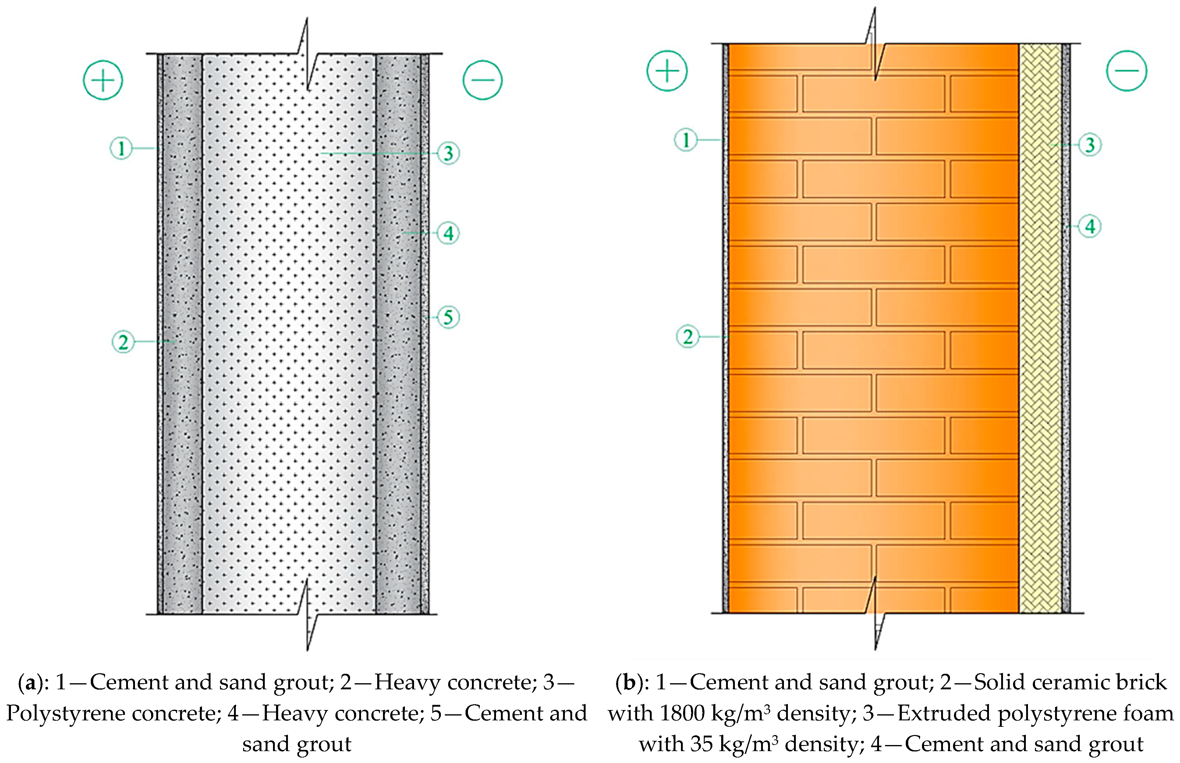
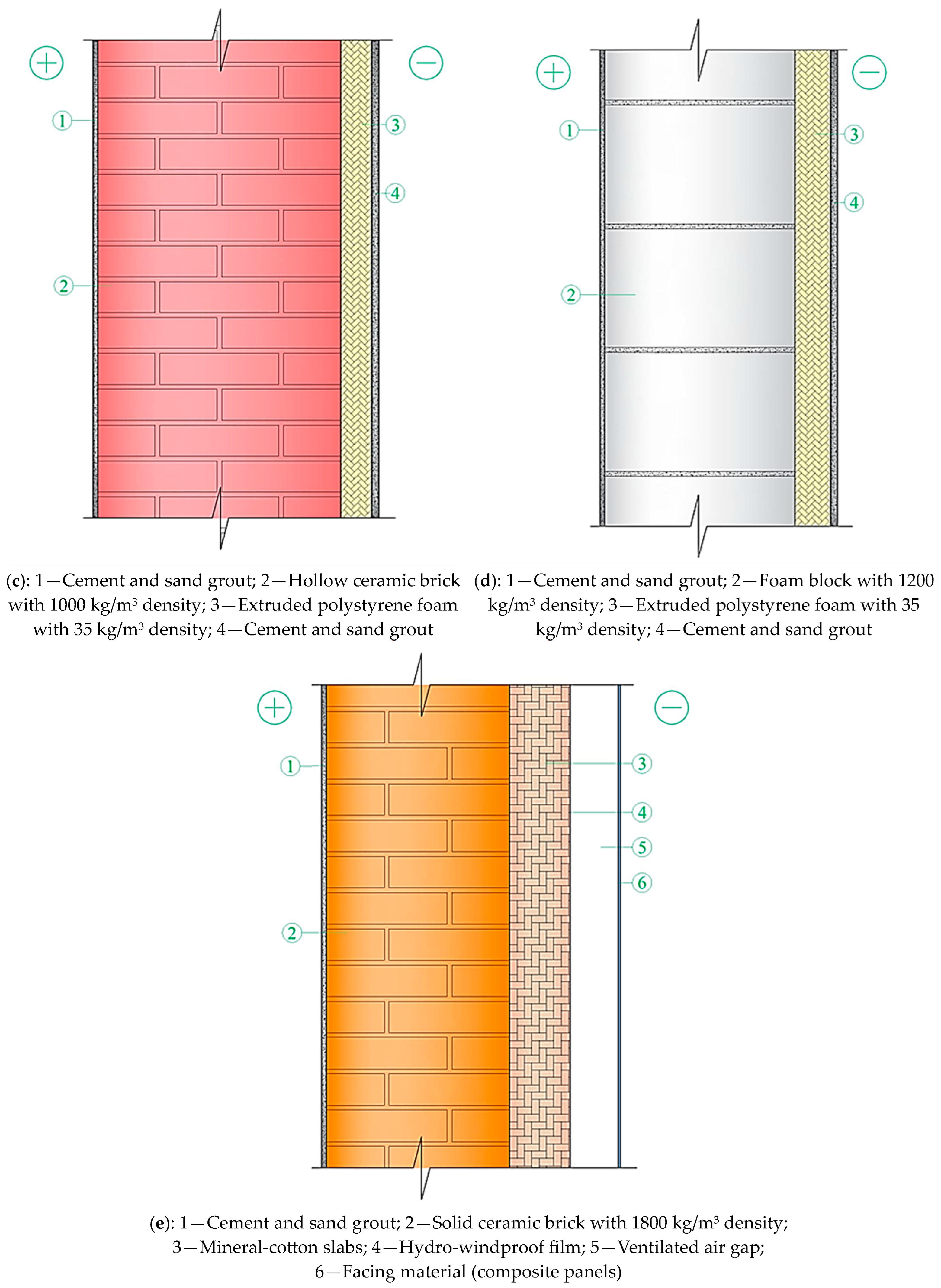
2.1. Studied Options of Multilayer Structures of Outer Shells

Our research examined five types of multilayer structures of outer shells, where a three-layer panel made of highly porous polystyrene concrete, obtained using a new technology [25] (Figure 1a), was proposed as a new design in comparison with existing structures of outer shells (Figure 1a,c–e).
The main thermal engineering characteristics of the studied multilayer structures of outer shells are presented in Table 1, Table 2, Table 3, Table 4 and Table 5 [27].

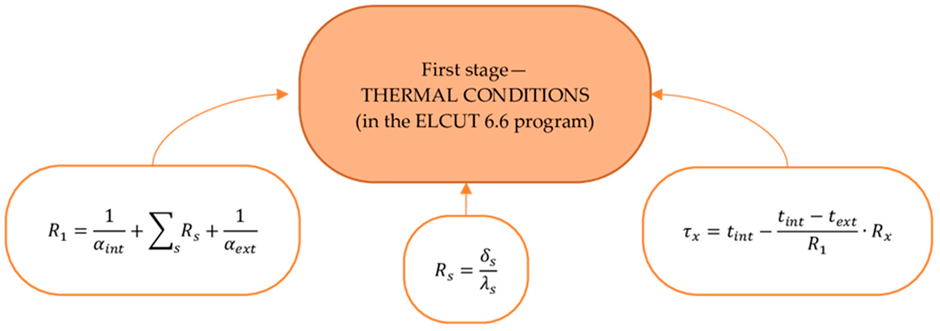
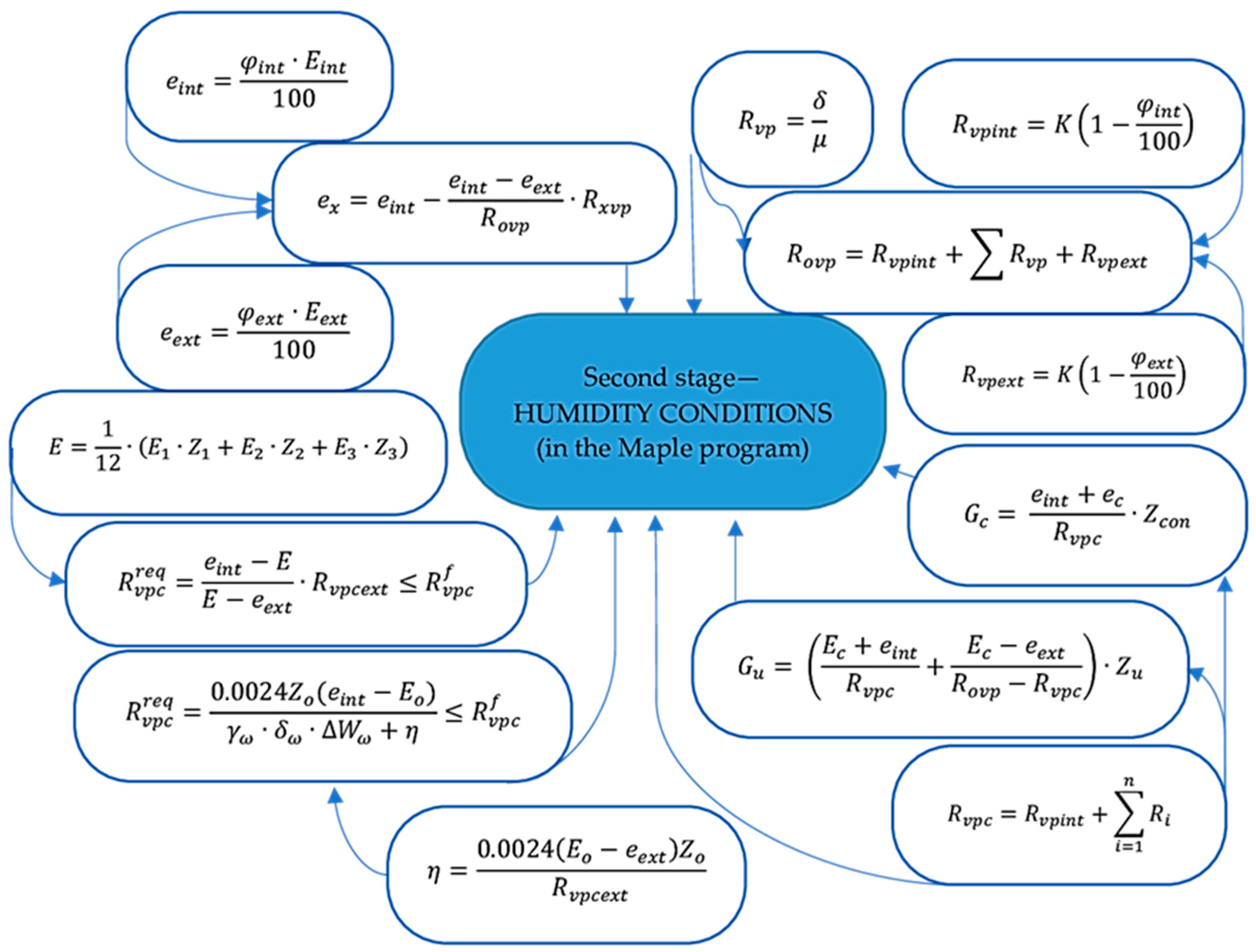
2.2. Outer Shells’ Thermal Efficiency Design Procedure

The thermal efficiency design procedure for the outer shells was carried out in three stages. Figure 2, Figure 3 and Figure 4 show the design procedure for all stages, which consist of thermal (Figure 2), humidity (Figure 3), and air conditions (Figure 4), carried out according to [27,28,29,30,31,32].

2.3. Climatic and Internal Boundary Conditions of the Region

The research examined a region located in the central part of the Republic of Kazakhstan. The main climatic indicators were adopted according to the standard [33,34] and are presented in Table 6.

3. Results and Discussion

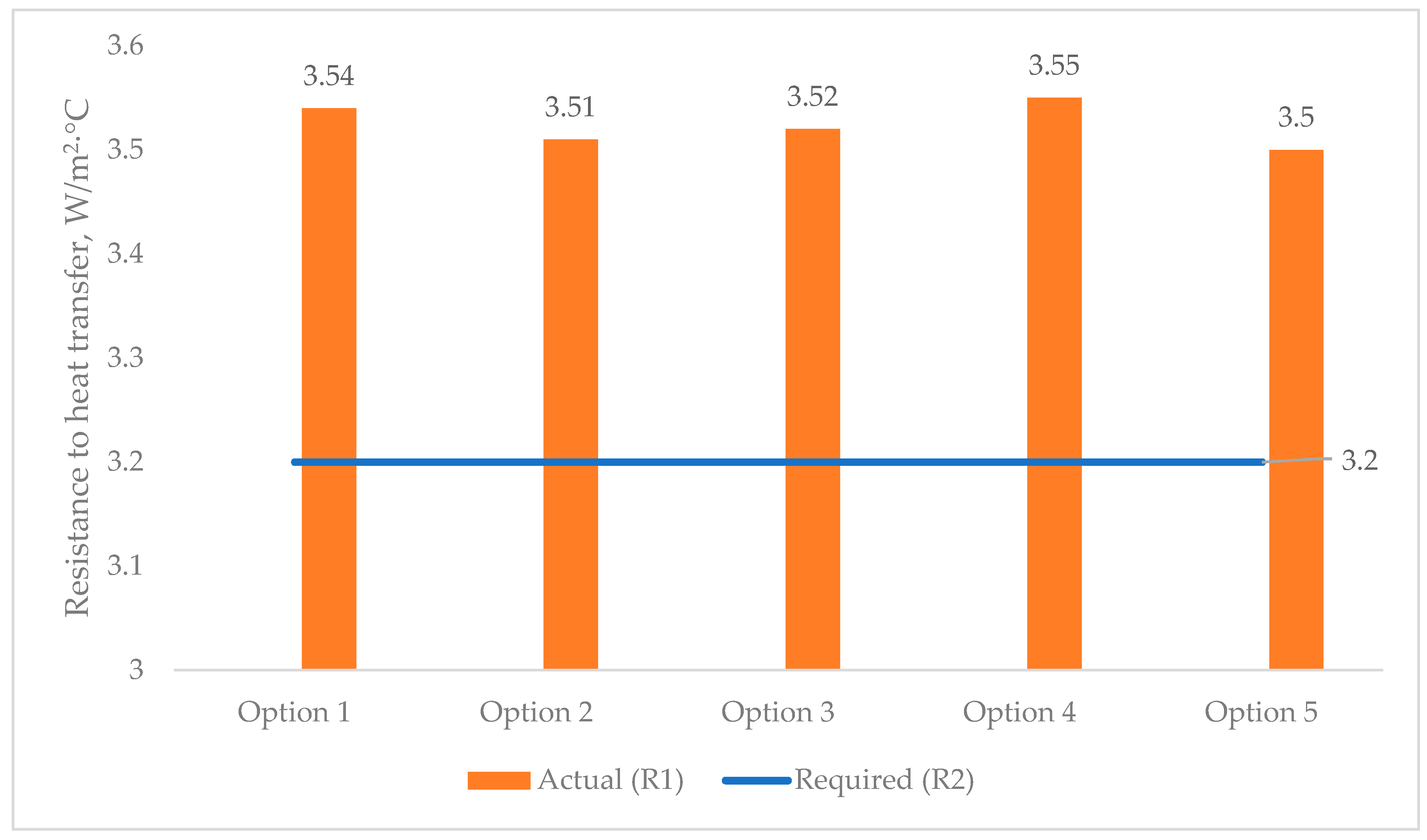
3.1. Determination of the Actual Heat Transfer Resistance of the Multilayer Structures of the Outer Shells

Figure 5 shows the analytical results of the actual heat transfer resistances of all the multilayer structures of the outer shells (Figure 1) in comparison with the required one (Table 6), obtained according to [27,34].

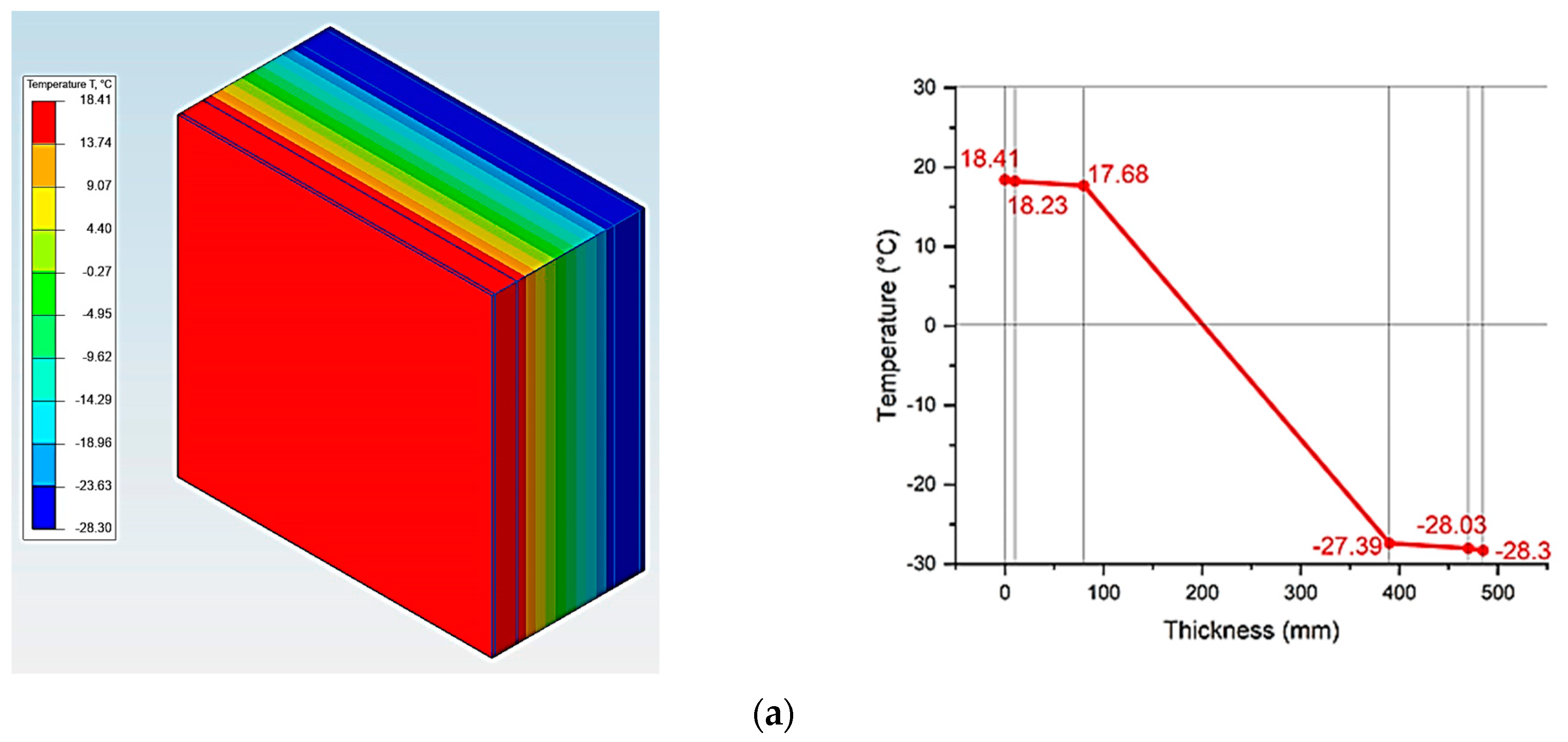
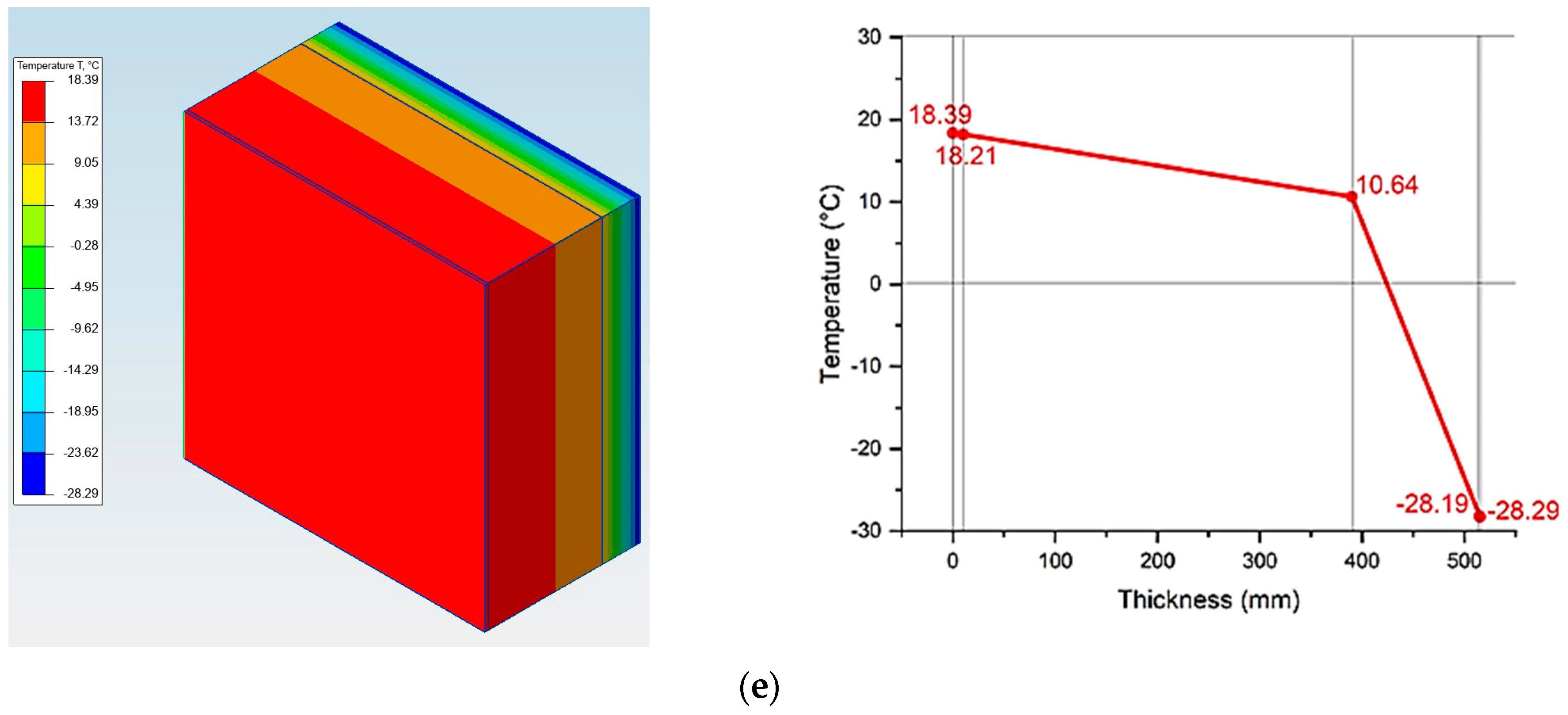
3.2. Research of Temperature Distribution at the Boundaries of The Multilayer Structures of the Outer Shells

Figure 6 shows an analysis of temperature fields of the outer shells, modeled in the ELCUT 6.6 software package [32,33,34,35,36].

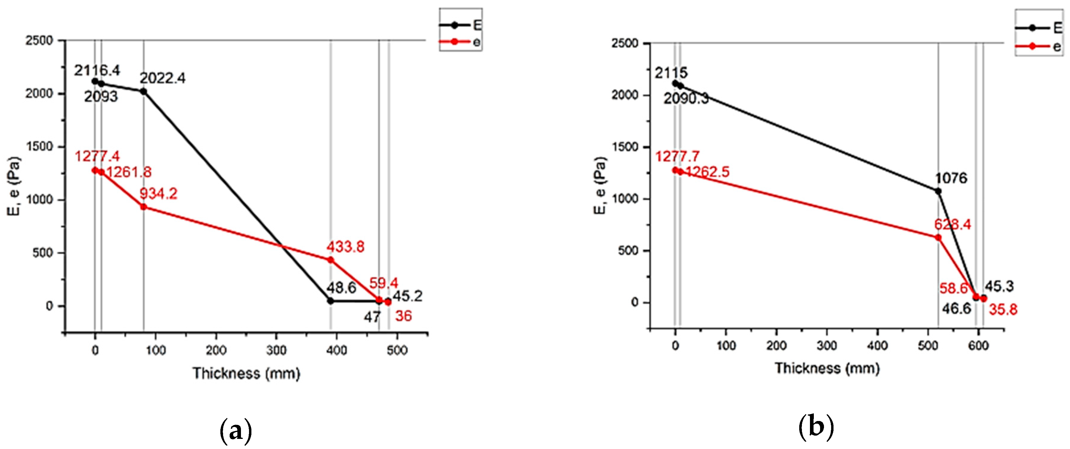
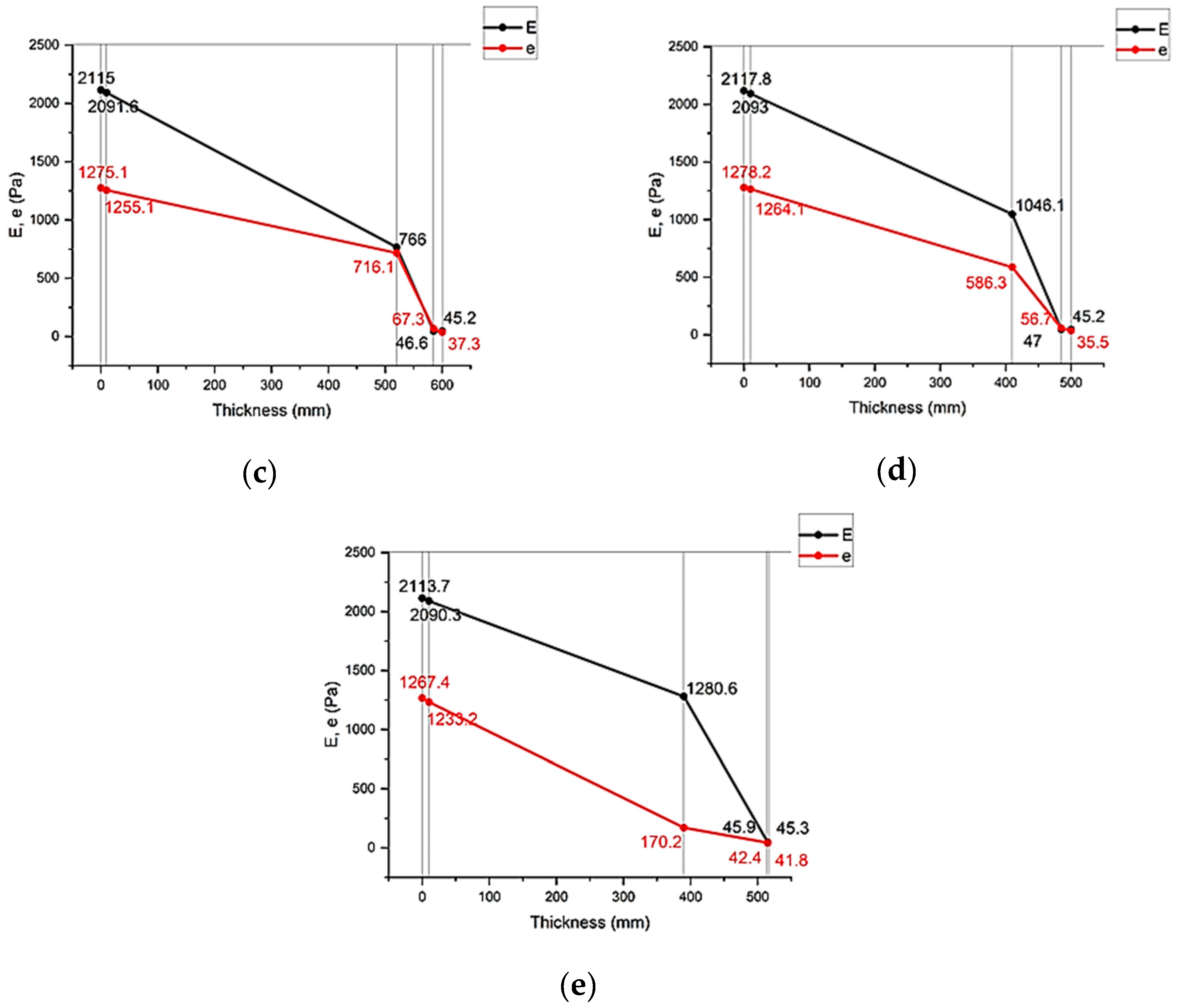
3.3. Calculation of Humidity Conditions of the Multilayer Structures of the Outer Shells

3.3.1. Calculation of Humidity Condensation in the Multilayer Structures of the Outer Shells

Figure 7 shows the results of the calculation of humidity condensation in the multilayer structures of the outer shells.

3.3.2. Calculation of the Amount of Moisture Condensing in the Multilayer Structures of the Outer Shells During the Period of Moisture Accumulation

Figure 8 shows the results of calculating the values of the amount of moisture condensing in the multilayer structures of the outer shells during the period of moisture accumulation.

3.3.3. Calculation of the Amount of Moisture Evaporated from the Multilayer Structures of the Outer Shells During the Drying Period

Figure 9 shows the results of calculating the amount of moisture evaporated from the multilayer structures of the outer shells during the drying period.

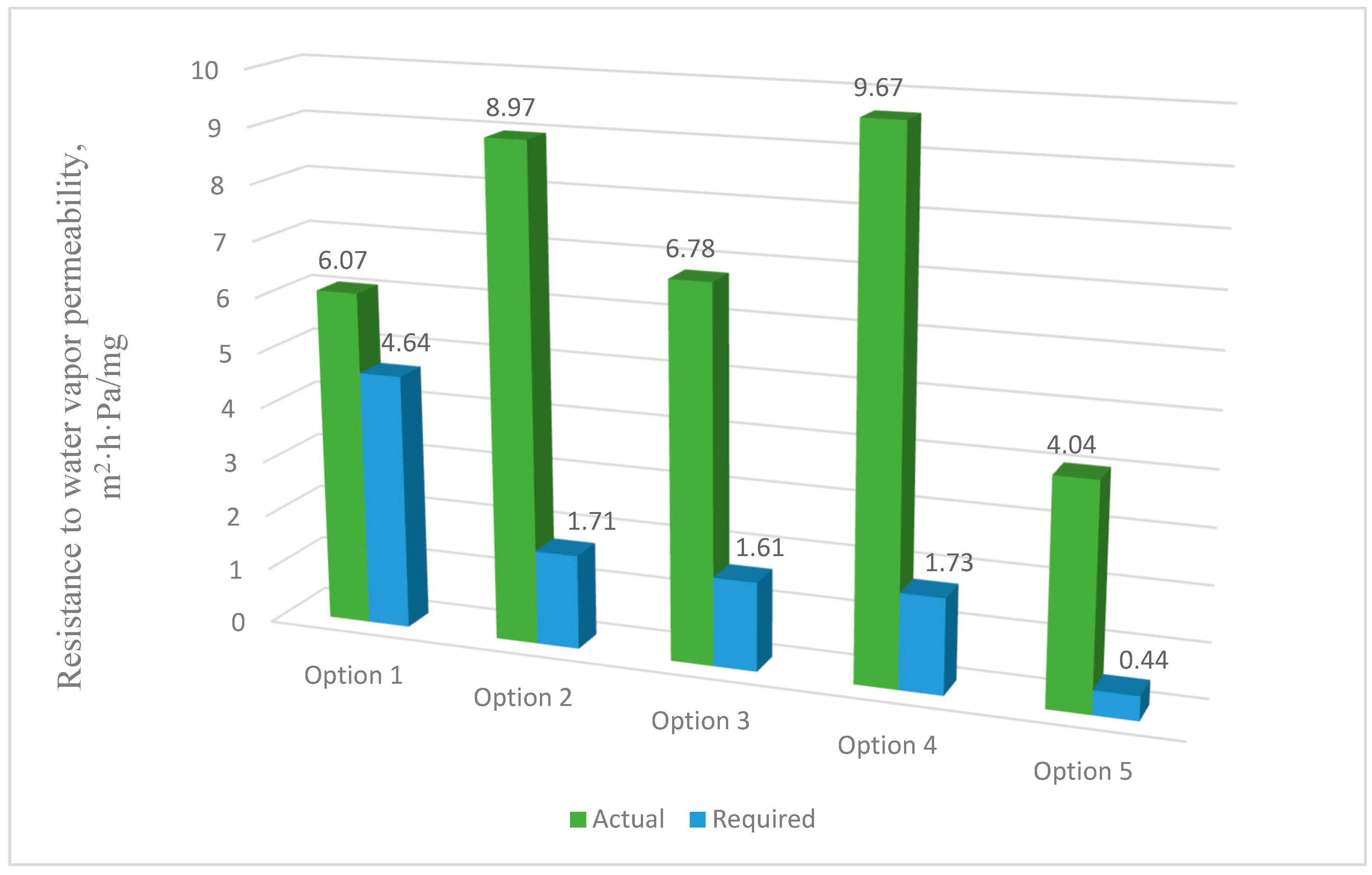
3.3.4. Conditions for the Inadmissibility of Moisture Accumulation in the Structures of the Outer Shells over the Annual Period of Operation ( R v p c f R v p c r e q )

Figure 10 shows the calculation of the values of the inadmissibility of moisture accumulation in the multilayer structures of the outer shells over an annual period of operation.

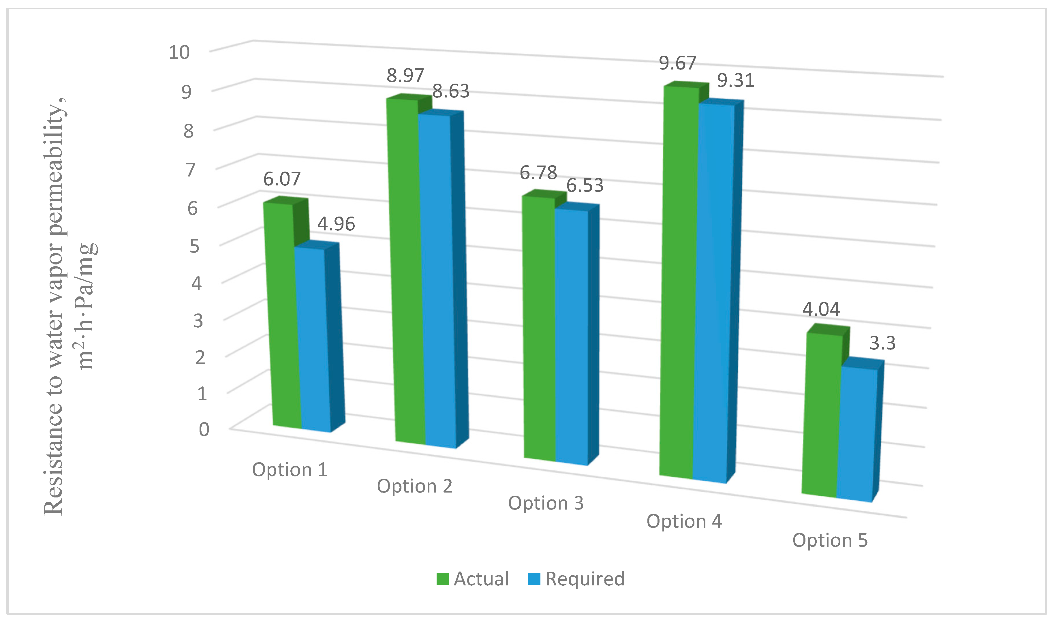
3.3.5. Conditions for the Inadmissibility of Moisture Accumulation in the Multilayer Structures of the Outer Shells During the Period of Moisture Accumulation ( R v p c f R v p c r e q )

Figure 11 shows the results of calculating the values of inadmissibility of moisture accumulation in the multilayer structures of the outer shells during the period of moisture accumulation.

3.4. Calculation of Air Conditions in the Multilayer Structures of the Outer Shells ( R u r e q R u f )

3.4.1. Calculation of Air Permeability Resistance of the Multilayer Structures of the Outer Shells

Table 7 presents the results of calculating the required and actual air permeability resistances of the multilayer structures of the outer shells.

3.4.2. Research of Temperature Distribution at the Boundaries of the Multilayer Structures of the Outer Shells Taking into Account Air Filtration

Table 8 presents the results of calculating the temperature distributions at the boundaries of the multilayer structures of the outer shells.

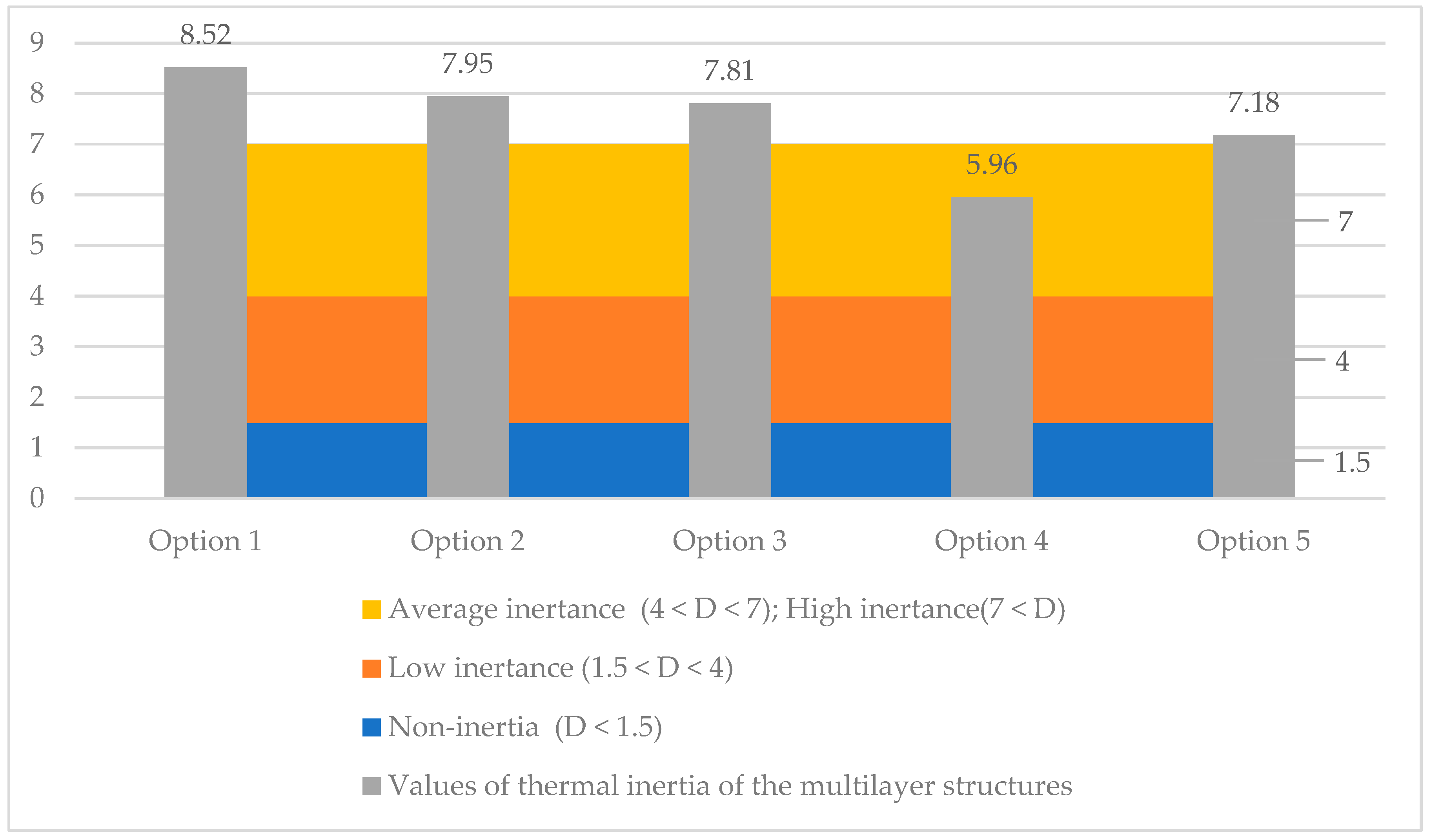
3.5. Research of Thermal Inertia of the Multilayer Structures of the Outer Shells

Figure 12 shows the results of calculating the values of thermal inertia of the multilayer structures of the outer shells.

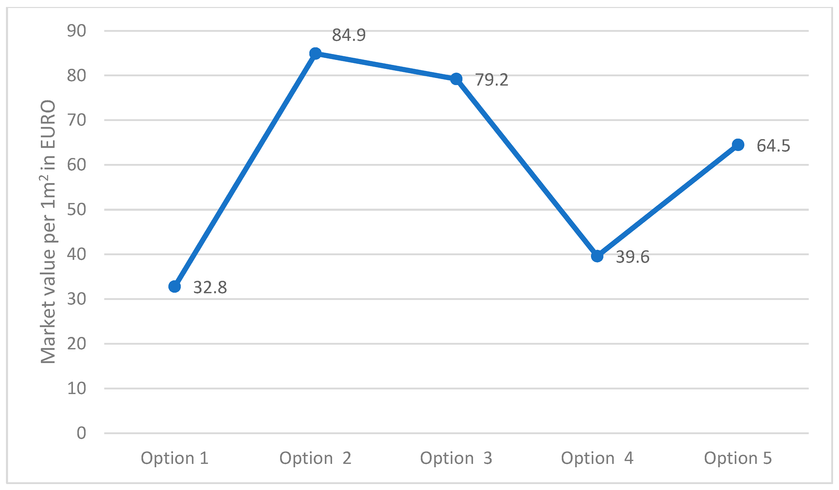
3.6. The Market Value of the Construction of the Studied Multilayer Enclosing Structures

Figure 13 shows the market values of the construction of the studied multilayer structures of external fences in the city of Karaganda per 1 m2.
This paper presents linking computational research of the multilayer structure of the cladding developed using a new technology—a three-layer panel made of highly porous polystyrene concrete (Figure 1a) [25]—in comparison with traditional ones (Figure 1b–e) using the ELCUT 6.6 software package [32] and the Maple computer algebra system. A multivariate analysis of all the multilayer structures of the outer shells was carried out in three stages, where the first stage analyzed the values of the thermal conditions (Figure 2), and the second and third stages analyzed the values of the humidity (Figure 3) and air (Figure 4) conditions. In the research, the main geometric and thermal engineering characteristics are presented in Figure 1 and Table 1, Table 2, Table 3, Table 4 and Table 5 [27,28]. The central part of the Republic of Kazakhstan (Karaganda) was chosen as the research region, the main climatic values of which were adopted according to [33,34].
The analysis of the first stage of the research showed (Figure 2) that the required heat transfer resistance (R2) of the specified region is 3.2 W/ m 2 · ° C, adopted according to the value of the degree-day of the heating period according to the standard [27,28]. Taking into account the value of the required heat transfer resistance (R2) in the research, the thickness of the multilayer structures of the outer shells was adopted taking into account R2, where the values of the actual resistances (R1) of heat transfer are presented in Figure 5, which vary in the range from 3.5 to 3.55 W/ m 2 · ° C; these values are almost equal at the specified thicknesses of the multilayer structures. Taking these circumstances into account, with the specified (Figure 5) equal accepted values, the thicknesses of traditional enclosures (Figure 1b–e) relative to the developed one (Figure 1a) increase by 25.77%, 23.71%, 3.09%, and 27.83%, respectively. Thus, due to the equating of the enclosure thicknesses, the analysis of temperature fields showed that the temperature on the inner surface of the enclosure is almost all similar, which is equal to 18.40 °C on average (Figure 6).
The analysis of the second stage of the research showed (Figure 3) that moisture accumulation occurs in all structures (Figure 7). With that, the calculation of the amount of accumulated moisture (Figure 8) showed that the values in traditional enclosure options 2 and 4 are 2.61% and 9.48% less, respectively, and for options 3 and 5 they are 27.94% and 119% more, respectively. However, the calculation of the amount of moisture evaporated in the multilayer structures of the outer shells during the drying period showed that all the accumulated moisture in the structures will evaporate (Figure 9). Thus, the condition for the inadmissibility of moisture accumulation in the multilayer structures of the outer shells was additionally analyzed during the annual period of operation (Figure 10) and during the period of moisture accumulation (Figure 11). In all cases, the condition ( R v p c 1 R v p c 2 ) is fulfilled, which emphasizes the positive aspect of the developed structure despite the significant difference in thickness relative to traditional ones.
The analysis of the third stage of the research showed (Figure 4) that in all the studied multilayer structures of the outer shells, the value of the required and actual resistance to air permeability satisfies the condition ( R u 2 R u 1 ), presented in Table 7. Thus, in the developed structure (Figure 1a) this value is significantly higher than in traditional ones, which had a positive effect on the values of the temperature fields of the enclosure. Thus, in the developed structure (Figure 1a), the temperature of the inner surface ( τ i n t ) remains high, even taking into account filtration (18.41 °C); in traditional structures (Figure 1b–e), the value of τ i n t decreases to 1.35 °C depending on the option of the traditional multilayer structure, which is an unfavorable factor in the cold period. Moreover, the analytical results of thermal inertia (D) of the developed (Figure 1a) and traditional multilayer structures (Figure 1b–e) showed that the developed structure, according to the value of D, belongs to the high inertia (7 < D) type and exceeds the traditional ones by 6.69%, 8.33%, 30.04% and 15.72%, respectively, which is also a positive moment in the cold period. In conclusion, an analysis of the market value of the studied multilayer structures of external fences was carried out (Figure 13), where it was found that the market prices of all traditional structures (Figure 1b–e) exceed the developed one by 1.2–2.5 times, depending on the design, which also emphasizes the positive aspects of the new design (Figure 1a).
The conducted research on the theoretical study of the developed design of the external fence is part of the research conducted by the authors of [25,31]. As noted above, the efficiency in terms of economic indicators is significant, which is due to the minimum consumption of materials [37,38,39] and rapid construction [40,41]. Since ready-made three-layer panels during installation do not imply a long construction period, as with the structures of ventilated facades [12,13,14,15] and facades made of block masonry [42,43]. In this regard, this type of construction is, by all criteria, the most optimal in the climatic conditions of Karaganda. As a disadvantage of this research, it can be noted that we did not take into account cold joints; however, we will solve and supplement this problem in subsequent research. At the same time, the results obtained in this research will positively complement the catalog of products for multilayer outer shells and can be used by research communities and design organizations in the design of residential buildings.

4. Conclusions

This paper presented computational research of a multilayer structure of the outer fence consisting of a three-layer panel made of highly porous polystyrene concrete developed using a new technology in comparison with traditional structures. The study covered such areas as thermal engineering indicators and the economic efficiency of the new design. As a result of a comprehensive study, the following was found:
-
Equating the thickness by the R1 value taking into account R2 of traditional multilayer structures to the developed one, the thickness of traditional structures increases from 3.09% to 27.83% depending on the option, which is ineffective from the point of view of the construction estimate.
-
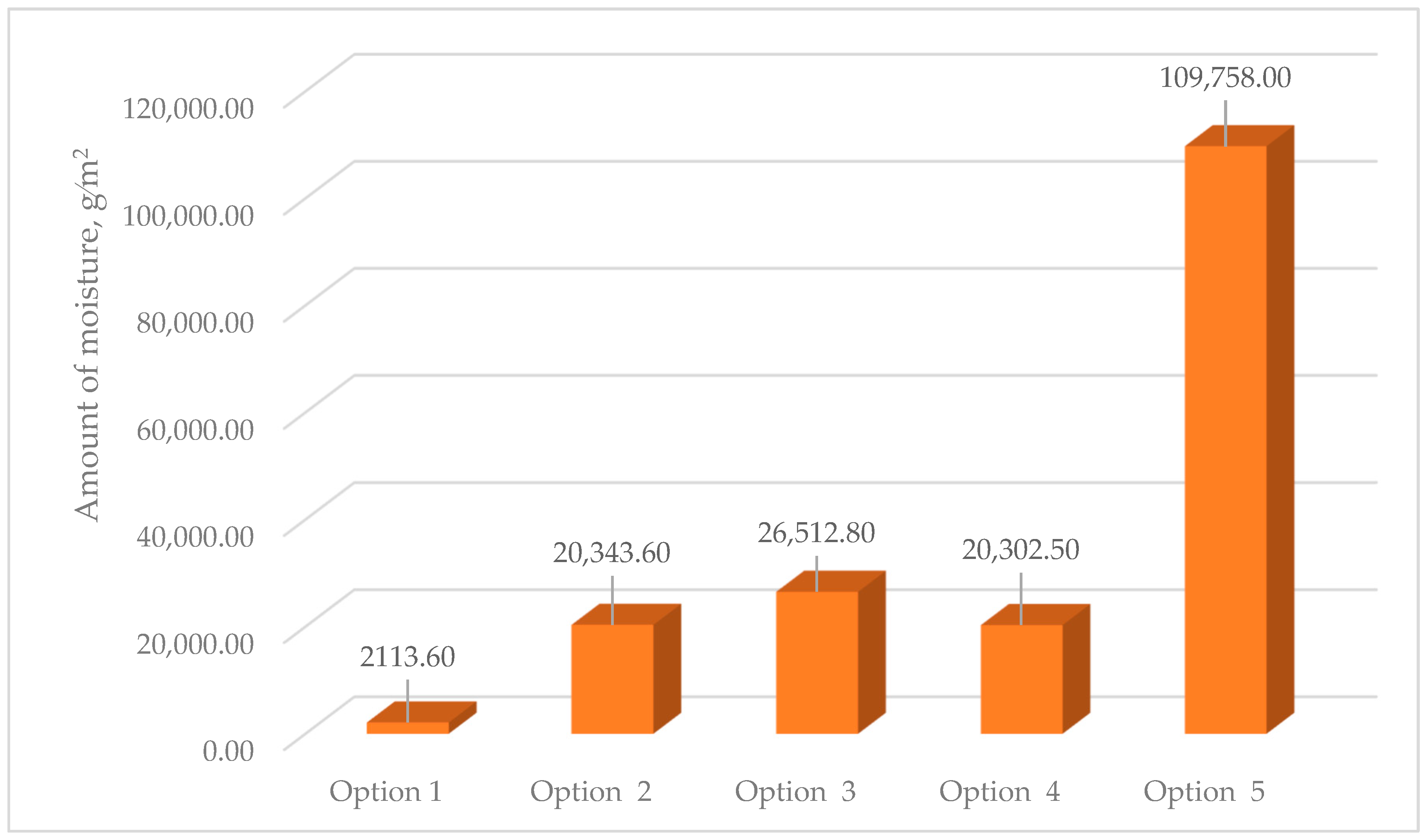
Moisture accumulation relative to the developed structure occurs in all the studied structures in the range of 2113.6–109,758 g/m2; if, in options 2 and 4 of traditional structures, moisture is collected by 2.61% and 9.48% less, respectively, then in options 3 and 5 moisture is collected by 27.94% and 119% more, respectively. However, the value of evaporated moisture during the drying period showed that all moisture will evaporate. At the same time, all structures meet the conditions for the inadmissibility of moisture for an annual period and the period of moisture accumulation.
-
The values of the actual and required air permeabilities satisfy the condition ( R u 2 R u 1 ), which affected the values of the temperature fields taking into account air filtration, where the developed structure showed a positive effect for this value, and in traditional structures the value of τ i n t decreased to 1.35 °C depending on the option; this will have an adverse effect in the cold period. The analytical results of the value of D of the developed and traditional multilayer structures showed that the developed structure by its value of D refers to high inertia (7 < D) [25,26] and exceeds traditional ones by up to 30.04% depending on the option, which affected the value of τ i n t taking into account filtration. It was also found that the market prices of all traditional structures exceed the developed one by 1.2–2.5 times, depending on the design, which also emphasizes the positive aspects of the new design.

Author Contributions

Conceptualization, N.Z. and T.S.; methodology, N.Z., U.I. and T.S.; investigation, N.Z., P.K. and T.S.; data curation, T.S., G.R. and M.R.; writing—original draft preparation, T.S., U.I. and G.R.; writing—review and editing, T.S., V.S. and M.K.; supervision, M.R., P.K. and T.S.; project administration, T.S., V.S. and M.K. Funding acquisition, T.S. and N.Z. All authors have read and agreed to the published version of the manuscript.

Funding

This research received no external funding.

Institutional Review Board Statement

Not applicable.

Informed Consent Statement

Informed consent was obtained from all subjects involved in the study.

Data Availability Statement

Data are contained within the article.

Conflicts of Interest

The authors declare no conflicts of interest.

Nomenclature

R 1 Actual heat transfer resistance of multilayer structures of outer shells, ( m 2 · ° C )/W;
α i n t Heat transfer coefficient of the inner surface of the cladding structure, α i n t = 8.7   W / ( m 2 · ° C ) ;
α e x t Heat transfer coefficient of the outer surface of the cladding structure, α e x t = 23   W / ( m 2 · ° C ) ;
R s Thermal resistance of the layer of the fragment’s homogeneous part, ( m 2 · ° C )/W;
δ s layer thickness, m;
λ s Thermal conductivity of the layer material under the operating conditions of structure A, W / ( m 2 · ° C ) ;
τ x Temperature in any section of the cladding structure, °C;
R x Resistance to heat transfer of the layers of the structure from the internal air to the section under consideration, ( m 2 · ° C )/W;
t i n t Indoor air temperature, °C;
t e x t Outside air temperature, °C;
e x Actual elasticity of water vapor in any section of the cladding structure, Pa;
e i n t Actual elasticity of water vapor in the internal air of the cladding structure, Pa;
e e x t Actual elasticity of water vapor in the outside air of the cladding structure, Pa;
R o v p Resistance to vapor permeability of a single layer or separate layer of a multilayer outer shell, m 2 · h · Pa / mg ;
R x v p Vapor permeability resistance of layers from the inner surface of the wall to section x;
R v p Vapor permeability resistance of a single layer or separate layer of the multilayer cladding structure, m 2 · h · Pa / mg ;
δ Layer thickness, m;
μ Calculated vapor permeability coefficient of the layer material, mg/(m·h·Pa);
R v p i n t ,   R v p e x t Vapor permeability resistance of the inner and outer wall surfaces, respectively, m 2 · h · Pa / mg ;
φ i n t ,   φ e x t Relative humidity of the indoor and outdoor air, respectively, %;
E i n t ,   E e x t Saturated partial pressure at the temperature of the indoor and outdoor air, respectively, Pa;
G c Amount of moisture condensing in the multilayer structure of the outer shell during the period of moisture accumulation, g/m2;
e i n t Actual elasticity of water vapor in the internal air of the cladding structure, Pa;
e c Actual elasticity of water vapor in the plane of possible condensation of the cladding structure, Pa;
Z c o n Duration of the condensation period, hours;
R v p c Vapor permeability resistance of the cladding structure part from the inner surface to the condensation plane, m 2 · h · Pa / mg ;
i = 1 n R i Vapor permeability resistance of the cladding structure part from the inner surface to the condensation plane, m 2 · h · Pa / mg ;
G u Amount of moisture evaporated from the multilayer structure of the outer shell during the drying period, g/m2;
e e x t Actual humidity of the outside air during the drying period, Pa;
E c Saturated water vapor pressure at the average temperature of the drying period, Pa;
Z u Duration of the drying period, hours;
R v p c e x t Resistance to vapor permeability of the part of the cladding structure between the plane of possible condensation and the outer surface of the cladding structure, m 2 · h · Pa / mg ;
E Elasticity of water vapor in the plane of possible condensation over an annual period, Pa;
E 1 ,   E 2 ,   E 3 Saturated pressure of water vapor, according to the temperatures of winter, spring-autumn, summer periods, respectively, Pa;
Z 1 ,   Z 2 ,   Z 3 Duration of winter, spring, autumn, summer periods, respectively, months;
γ ω Density of the material of the moistened layer, kg/m3;
δ ω Thickness of the moistened layer, m;
Δ W ω Maximum permissible increase in the calculated mass ratio of moisture in the material of the moistened layer, %;
E o Partial pressure of the condensation zone during the period of moisture accumulation, Pa;
Z o Duration of condensation period, months;
R u r e q Required air permeability resistance,   P a · m 2 · h / kg ;
R u f Actual air permeability resistance, P a · m 2 · h / kg ;
Δ p Calculated value of the total pressure difference due to temperature difference and wind, Pa;
G H = 0.5 Transverse air permeability for external walls, kg / m 2 · h ;
γ e x t ,   γ i n t Density of cold and warm air, respectively, kg/m3;
HBuilding height (from the floor level of the first floor to the top of the exhaust shaft), m;
ϑ Maximum of average wind speeds by rhumbs for January, m/s;
eBase of natural logarithms;
GAmount of air filtered through the structure per unit of time, kg/(m2 · h);
c =1Specific heat capacity of air;
DThermal inertia;
s Heat absorption, W/ ( m 2 · ° C ).

References

  1. Available online: https://www.primeminister.kz/ru/news/reviews/pyat-napravleniy-novoy-zhilishchnoy-programmy-itogi-pilotnogo-proekta-po-medstrahovaniyu-i-ceny-na-produkty-o-chem-govorili-na-ocherednom-zasedanii-pravitelstva (accessed on 24 July 2024).
  2. Kazakhstani Center for Modernization and Development of Housing and Public Utilities. Available online: https://zhkh.kz/ (accessed on 24 July 2024).
  3. Matic, D.; Calzada, J.R.; Eric, M.; Babin, M. Economically feasible energy refurbishment of prefabricated building in Belgrade, Serbia. Energy Build. 2015, 98, 74–81. [Google Scholar] [CrossRef]
  4. Michalak, P. Selected Aspects of Indoor Climate in a Passive Office Building with a Thermally Activated Building System: A Case Study from Poland. Energies 2021, 14, 860. [Google Scholar] [CrossRef]
  5. Rinquet, L.; Schwab, S. eREN Energetic refurbishment—A global approach for the building envelope. Energy Procedia 2017, 122, 109–114. [Google Scholar] [CrossRef]
  6. Nik, V.M.; Mata, E.; Kalagasidis, A.S.; Scartezzini, J.L. Effective and robust energy retrofitting measures for future climatic conditions—Reduced heating demand of Swedish households. Energy Build. 2016, 121, 176–187. [Google Scholar] [CrossRef]
  7. Zhangabay, N.; Kudabayev, R.A.; Mizamov, N.; Imanaliyev, K.; Kolesnikov, A.; Moldagaliyev, A.; Merekeyeva, A. Study of the model of the phase transition envelope taking into account the process of thermal storage under natural draft and by air injection. Case Stud. Constr. Mater. 2023, 18, e02050. [Google Scholar] [CrossRef]
  8. Kudabayev, R.; Mizamov, N.; Zhangabay, N.; Suleimenov, U.; Kostikov, A.; Vorontsova, A.; Buganovs, S.; Umbitaliyev, A.; Kalshabekova, E.; Aldiyarov, Z. Construction of a model for an enclosing structure with a heat-accumulating material with phase transition taking into account the process of solar energy accumulation. East. Eur. J. Enterp. Technol. 2022, 6, 26–37. [Google Scholar] [CrossRef]
  9. Zhangabay, N.; Giyasov, A.; Ybray, S.; Tursunkululy, T.; Kolesnikov, A. Field thermovision study of externsl enclosure for multi-storey residential building under climatic conditions of Northern Kazakhstan. Constr. Mater. Prod. 2024, 7, 1. [Google Scholar] [CrossRef]
  10. Sheikholeslami, M.; Hazim, R.A. Analyzing efficiency of solar heat storage unit within a building including trombe wall equipped with phase change material in existence of fins. J. Build. Eng. 2023, 71, 106406. [Google Scholar] [CrossRef]
  11. Pirasaci, T. Investigation of phase state and heat storage form of the phase change material (PCM) layer integrated into the exterior walls of the residential-apartment during heating season. Energy. 2020, 207, 118176. [Google Scholar] [CrossRef]
  12. Zhangabay, N.; Baidilla, I.; Tagybayev, A.; Sultan, B. Analysis of Thermal Resistance of Developed Energy-Saving External Enclosing Structures with Air Gaps and Horizontal Channels. Buildings 2023, 13, 356. [Google Scholar] [CrossRef]
  13. Coppola, O.; De Luca, G.; Franco, A.; Bonati, A. Experimental tests for seismic assessment of ventilated façades. Procedia Struct. Integr. 2023, 44, 758–765. [Google Scholar] [CrossRef]
  14. Zheng, C.; Chen, C.; Hong, X.; Zhang, W.; Yang, R.; Shi, F. Experimental evaluation of the thermal, lighting, and energy performances of a mechanically ventilated double-skin façade with Venetian blinds and a light shelf. Energy Build. 2024, 306, 113947. [Google Scholar] [CrossRef]
  15. Borodulin, V.Y.; Nizovtsev, M.I. Modeling heat and moisture transfer of building facades thermally insulated by the panels with ventilated channels. J. Build. Eng. 2021, 40, 102391. [Google Scholar] [CrossRef]
  16. Vasiliev, N.; Stuglev, N.; Utkov, E.; Melnik, I. High ventilated facades and wet. StroyMnogo 2017, 4, 1–19. Available online: https://cyberleninka.ru/article/n/navesnye-ventiliruemye-fasady-i-mokrye/viewer (accessed on 24 July 2024).
  17. Zheng, Z.; Xiao, J.; Yang, Y.; Xu, F.; Zhou, J.; Liu, H. Optimization of exterior wall insulation in office buildings based on wall orientation: Economic, energy and carbon saving potential in China. Energy 2024, 290, 130300. [Google Scholar] [CrossRef]
  18. Kitayama, S.; Iuorio, O.; Josa, I.; Borrion, A.; Black, L. Determining the carbon footprint reduction of reusing lightweight exterior infill walls: A case study of a school building in the United Kingdom. J. Clean. Prod. 2024, 469, 143061. [Google Scholar] [CrossRef]
  19. Gonçalves, M.; Simões, N.; Serra, C.; Flores-Colen, I. A review of the challenges posed by the use of vacuum panels in external insulation finishing systems. Appl. Energy 2020, 257, 114028. [Google Scholar] [CrossRef]
  20. Zhuang, J.; Ghaffar, S.H.; Fan, M.; Corker, J. Restructure of expanded cork with fumed silica as novel core materials for vacuum insulation panels. Compos. Part B Eng. 2017, 127, 215–221. [Google Scholar] [CrossRef]
  21. Simmler, H.; Brunner, S. Vacuum insulation panels for building application: Basic properties, aging mechanisms and service life. Energy Build 2005, 37, 1122–1131. [Google Scholar] [CrossRef]
  22. Joo, N.; Song, S. Improvement of thermal insulation performance of precast concrete curtain walls for apartment buildings. Energy Build. 2023, 296, 113350. [Google Scholar] [CrossRef]
  23. Cuong, N.; Gayoon, L.; An, H.; An, S.; Han, S.W.; Lee, K. Experimental evaluation of a vertical heat bridge insulation system for the structural performance of multi-residential buildings. Structures 2023, 58, 105686. [Google Scholar] [CrossRef]
  24. Kim, S.; Hong, W.; Ko, H.; Kim, J. The energy efficient expansion remodeling construction method of bearing wall apartment buildings with pre-cast composite structural systems. Energy Build. 2013, 66, 714–723. [Google Scholar] [CrossRef]
  25. Samoilova, T.; Rakhimov, M.; Rakhimova, G.; Zhangabay, N. Effect of heat treatment of expanded polystyrene concrete on its compressive strength. Technobius 2024, 4, 0059. [Google Scholar] [CrossRef]
  26. Khan, M.; Samoilova, T.; Rakhimova, G.; Rakhimov, M. Raw Material Mix for Heat Insulation Products. 2024, p. 9341. Available online: https://qazpatent.kz/ru (accessed on 11 August 2024).
  27. Set of Rules of the Republic of Kazakhstan 2.04-107-2022. Thermal Protection of Buildings. Set of Rules of the Republic of Kazakhstan. Committee for Construction and Housing and Public Utilities. Astana 2022, 135. Available online: https://online.zakon.kz/Document/?doc_id=39838250 (accessed on 25 July 2024).
  28. Set of Rules 50.13330.2012—Set of rules “Thermal Protection of Buildings”—Date of Introduction 1 July 2013. Available online: https://aluprof.su/index.php/dokumentatsiya/gosty-i-snipy (accessed on 25 July 2024).
  29. Sanitary Standards of the Republic of Kazakhstan 2.04-04-2011 Thermal Protection of Buildings: State Standards in the Field of Architecture, Urban Planning and Construction. Code of Rules of the Republic of Kazakhstan. JSC “KazNIISA”, LLP “Astana Stroy-Consulting”, 2013; Approved and Enacted on 1 July 2015. Available online: https://hoffmann.kz/files/12_SN_RK_2-04-04-2011.pdf (accessed on 18 July 2024).
  30. Sanitary Regulations of the Republic of Kazakhstan 2.04-106-2012 Design of Thermal Protection of Buildings: State Standards in the Field of Architecture, Urban Planning and Construction. Code of Rules of the Republic of Kazakhstan. JSC “KazNIISA”, LLP “Astana Stroy-Consulting”, 2013. Approved and Enacted on 1 July 2015. Available online: https://online.zakon.kz/Document/?doc_id=35957424 (accessed on 18 July 2024).
  31. Zhangabay, N.; Bakhbergen, S.; Aldiyarov, Z.; Tursunkululy, T.; Kolesnikov, A. Analysis of thermal efficiency of external fencing made of innovative ceramic blocks. Constr. Mater. Prod. 2024, 7, 1. [Google Scholar] [CrossRef]
  32. Available online: https://elcut.ru (accessed on 10 July 2024).
  33. Code of Rules of the Republic of Kazakhstan 2.04-01-2017 Building Climatology: State Standards in the Field of Architecture, Urban Planning and Construction. Code of Rules of the Republic of Kazakhstan. JSC “KazNIISA”, LLP “Astana Stroy-Consulting”, 2017; Approved and Enacted on 20 December 2017. Available online: https://online.zakon.kz/m/document/?doc_id=37599018 (accessed on 18 July 2024).
  34. Available online: https://www.kazhydromet.kz/ru/ (accessed on 18 July 2024).
  35. Sakhin, V.V.; Gerliman, E.M.; Brykov, N.A. Heat Transfer in Exercises and Problems; University of Baltimore: St. Petersburg, Russia, 2019; 165p, Available online: http://www.library.voenmeh.ru/cnau/8yCJlPwJVElpmHv.pdf (accessed on 10 July 2024).
  36. Isachenko, V.P.; Osipov, V.A.; Sukomel, A.S. Heat Transfer; Energoizdat: Moscow, Russia, 1981; p. 416. Available online: https://djvu.online/file/BXpZJMYm45EsC (accessed on 10 July 2024).
  37. Ucar, A.; Balo, F. Effect of fuel type on the optimum thickness of selected insulation materials for the four different climatic regions of Turkey. Appl. Energy 2009, 86, 730–736. [Google Scholar] [CrossRef]
  38. Kaynaklı, O. A study on residential heating energy requirement and optimum insulation thickness. Renew. Energy 2008, 33, 1164–1172. [Google Scholar] [CrossRef]
  39. Dombaycı, O.A. The environmental impact of optimum insulation thickness for external walls of buildings. Build. Environ. 2007, 42, 3855–3859. [Google Scholar] [CrossRef]
  40. Prasad, S.; William, L.; Hong Hao, H.; Chen, W. Prefabricated concrete sandwich and other lightweight wall panels for sustainable building construction: State-of-the-art review. J. Build. Eng. 2024, 89, 109391. [Google Scholar] [CrossRef]
  41. O’Hegarty, R.; Kinnane, O. Review of precast concrete sandwich panels and their innovations. Construct. Build. Mater. 2020, 233, 117145. [Google Scholar] [CrossRef]
  42. Gupta, V.; Pathak, K.; Kumar, R.; Miglani, A.; Siddique, S. Production of colored bi-layered bricks from stone processing wastes: Structural and spectroscopic characterization. Constr. Build. Mater. 2021, 278, 122339. [Google Scholar] [CrossRef]
  43. Khattak, N.; Derakhshan, H.; Thambiratnam, D.; Malomo, D.; Perera, J. Modelling the in-plane/out-of-plane interaction of brick and stone masonry structures using Applied Element Method. J. Build. Eng. 2023, 76, 107175. [Google Scholar] [CrossRef]
Figure 1. Options of multilayer structures of outer shells. An explanation of the numbering of the layers is given in Table 1, Table 2, Table 3, Table 4 and Table 5: (a)—three-layer panel made of highly porous polystyrene concrete (option 1); (b)—traditional enclosure made of solid ceramic brick (option 2); (c)—traditional enclosure made of hollow ceramic brick (option 3); (d)—traditional enclosure made of foam block (option 4); (e)—outer shell with a ventilated layer (option 5).
Materials 17 04133 g001aMaterials 17 04133 g001b
Figure 2. Algorithm for calculating the thermal conditions of the multilayer structures of the outer shells [30].
Materials 17 04133 g002
Figure 3. Algorithm for calculating the humidity conditions of the multilayer structures of the outer shells [25].
Materials 17 04133 g003
Figure 4. Algorithm for calculating the air conditions of the multilayer structures of the outer shells [25].
Materials 17 04133 g004
Figure 5. Values of actual (R1) and required (R2) heat transfer resistances of the multilayer structures of the outer shells: option 1—three-layer panel made of highly porous polystyrene concrete; option 2—traditional enclosure made of solid ceramic brick; option 3—traditional enclosure made of hollow ceramic brick; option 4—traditional enclosure made of foam block; option 5—outer shell with a ventilated layer.
Materials 17 04133 g005
Figure 6. Values of temperature fields of the multilayer structures of the outer shells: (a)—three-layer panel made of highly porous polystyrene concrete (option 1); (b)—traditional enclosure made of solid ceramic brick (option 2); (c)—traditional enclosure made of hollow ceramic brick (option 3); (d)—traditional enclosure made of foam block (option 4); (e)—outer shell with a ventilated layer (option 5).
Materials 17 04133 g006aMaterials 17 04133 g006bMaterials 17 04133 g006c
Figure 7. Values of humidity condensation of the multilayer structures of the outer shells: (a)—three-layer panel made of highly porous polystyrene concrete (option 1); (b)—traditional enclosure made of solid ceramic brick (option 2); (c)—traditional enclosure made of hollow ceramic brick (option 3); (d)—traditional enclosure made of foam block (option 4); (e)—outer shell with a ventilated layer (option 5).
Materials 17 04133 g007aMaterials 17 04133 g007b
Figure 8. Values of the amount of moisture condensing in the multilayer structures of the outer shells during the period of moisture accumulation: option 1—three-layer panel made of highly porous polystyrene concrete; option 2—traditional enclosure made of solid ceramic brick; option 3—traditional enclosure made of hollow ceramic brick; option 4—traditional enclosure made of foam block; option 5—outer shell with a ventilated layer.
Materials 17 04133 g008
Figure 9. Values of the amount of moisture evaporated from the multilayer structures of the outer shells during the drying period: option 1—three-layer panel made of highly porous polystyrene concrete; option 2—traditional enclosure made of solid ceramic brick; option 3—traditional enclosure made of hollow ceramic brick; option 4—traditional enclosure made of foam block; option 5—outer shell with a ventilated layer.
Materials 17 04133 g009
Figure 10. Values of the inadmissibility of moisture accumulation in the multilayer structures of the outer shells over an annual period of operation: option 1—three-layer panel made of highly porous polystyrene concrete; option 2—traditional enclosure made of solid ceramic brick; option 3—traditional enclosure made of hollow ceramic brick; option 4—traditional enclosure made of foam block; option 5—outer shell with a ventilated layer.
Materials 17 04133 g010
Figure 11. Values of the inadmissibility of moisture accumulation in the multilayer structures of the outer shells during the period of moisture accumulation: option 1—three-layer panel made of highly porous polystyrene concrete; option 2—traditional enclosure made of solid ceramic brick; option 3—traditional enclosure made of hollow ceramic brick; option 4—traditional enclosure made of foam block; option 5—outer shell with a ventilated layer.
Materials 17 04133 g011
Figure 12. Values of thermal inertia of the multilayer structures of the outer shells: option 1—three-layer panel made of highly porous polystyrene concrete; option 2—traditional enclosure made of solid ceramic brick; option 3—traditional enclosure made of hollow ceramic brick; option 4—traditional enclosure made of foam block; option 5—outer shell with a ventilated layer.
Materials 17 04133 g012
Figure 13. Market values of multilayer structures of the outer shells per 1 m2.
Materials 17 04133 g013
Table 1. Thermal engineering characteristics of a three-layer panel made of highly porous polystyrene concrete (option 1), shown in Figure 1a.
LayerLayer Thickness, mmThermal Conductivity for Operating Zone A, λ (W/(m·°C)Heat Absorption, S (W/(m·°C)Vapor Permeability, μ (mg/m·h·Pa)Air Permeability Resistance, RU (m2·h·Pa/kg)
1Cement and sand grout100.769.60.09373
2Heavy concrete701.7416.770.0319,620
3Polystyrene concrete3100.0952.070.08779
4Heavy concrete801.7416.770.0319,620
5Cement and sand grout150.769.60.09373
Table 2. Thermal engineering characteristics of the multilayer structure of the outer shell made of solid ceramic brick (option 2), shown in Figure 1b.
LayerLayer Thickness, mmThermal Conductivity for Operating Zone A, λ (W/(m·°C)Heat Absorption, S (W/(m·°C)Vapor Permeability, μ (mg/m·h·Pa)Air Permeability Resistance, RU (m2·h·Pa/kg)
1Cement and sand grout100.769.60.09373
2Solid ceramic brick with 1800 kg/m3 density2100.79.20.1118
3Extruded polystyrene foam with 35 kg/m3 density750.0290.360.01879
4Cement and sand grout150.769.60.09373
Table 3. Thermal engineering characteristics of the multilayer structure of the outer shell made of hollow ceramic brick (option 3), shown in Figure 1c.
LayerLayer Thickness, mmThermal Conductivity for Operating Zone A, λ (W/(m·°C)Heat Absorption, S (W/(m·°C)Vapor Permeability, μ (mg/m·h·Pa)Air Permeability Resistance, RU (m2·h·Pa/kg)
1Cement and sand grout100.769.60.09373
2Hollow ceramic brick with 1000 kg/m3 density5100.476.160.172
3Extruded polystyrene foam with 35 kg/m3 density650.0290.360.01879
4Cement and sand grout150.769.60.09373
Table 4. Thermal engineering characteristics of the multilayer structure of the outer shell made of foam block (option 4), shown in Figure 1d.
LayerLayer Thickness, mmThermal Conductivity for Operating Zone A, λ (W/(m·°C)Heat Absorption, S (W/(m·°C)Vapor Permeability, μ (mg/m·h·Pa)Air Permeability Resistance, RU (m2·h·Pa/kg)
1Cement and sand grout100.769.60.09373
2Foam block with 1200 kg/m3 density4000.528.170.075196
3Extruded polystyrene foam with 35 kg/m3 density750.0290.360.01879
4Cement and sand grout150.769.60.09373
Table 5. Thermal engineering characteristics of the multilayer structure of the outer shell with a ventilated layer (option 5), shown in Figure 1e.
LayerLayer Thickness, mmThermal Conductivity for Operating Zone A, λ (W/(m·°C)Heat Absorption, S (W/(m·°C)Vapor Permeability, μ (mg/m·h·Pa)Air Permeability Resistance, RU (m2·h·Pa/kg)
1Cement and sand grout100.769.60.09373
2Solid ceramic brick with 1800 kg/m3 density3800.79.20.1118
3Mineral-cotton slabs1250.0450.740.31.5
4Hydro-windproof film-0.76-0.09150
5Ventilated air gap100----
6Facing material (composite panels)5----
Table 6. Climatic and internal boundary conditions.
IndicatorsValues
1Development regionKaraganda, Republic of Kazakhstan
2Humidity conditions of the roomNormal
3Humidity zoneDry
4Operating conditions of cladding structuresA
5Absolute max. temperature40.2 °C.
6Absolute min. temperature–42.9 °C
7Average annual temperature3.7 °C
8Average temperature of the coldest 5-day period with a probability of 0.92–28.9 °C
9Average max. temperature of the warmest month (July)26.8 °C.
10Max. amplitude of daily fluctuations in outdoor air temperature in July12.9 °C
11Average monthly outdoor air temperature for July20.4 °C
12Average monthly temperature of the coldest month (January)–13.6 °C
13Average relative humidity of the coldest month (January)79%
14Average annual humidity65%
15Maximum of average speeds by rhumbs in January6.6 м/c
16Duration of the heating season207 days
17Internal temperature in winter20 °C
18Internal humidity55%
19Required design resistance according to the degree-day of the heating period3.2 W/m2 °C
Table 7. Values of the required and actual air permeability resistances of the multilayer structures of the outer shells.
SchemesRequired Air Permeability Resistance Depending on the Building HeightActual Air Permeability ResistanceFulfillment of the Condition
H = 3 mH = 15 m
1Option—143.7975.0730,131.91Done
2Option—243.7975.07719.9Done
3Option—343.7975.07703.9Done
4Option—443.7975.07822.9Done
5Option—543.7975.07419.4Done
Table 8. Values of temperature distributions at the boundaries of the multilayer structures of the outer shells.
Condition τ Schemes
Option 1Option 2Option 3Option 4Option 5
Without taking into account air filtration, °C
according to Figure 3
τ i n t 18.4118.4018.4018.4218.39
τ 1 18.2318.2118.2218.2318.21
τ 2 17.688.053.147.6310.62
τ 3 −27.39−28.02−28.02−28.03−28.19
τ 4 −28.03----
τ e x t −28.30−28.29−28.30−28.30−28.29
Taking into account air filtration,
°C
τ i n t 18.4118.2518.2518.2918.14
τ 1 18.2318.0518.0518.0917.93
τ 2 17.677.212.096.879.40
τ 3 −27.40−28.10−28.10−28.10−28.29
τ 4 −28.03----
τ e x t −28.30−28.35−28.35−28.35−28.38
Difference%Up to 0.510.433.49.9611.5
Disclaimer/Publisher’s Note: The statements, opinions and data contained in all publications are solely those of the individual author(s) and contributor(s) and not of MDPI and/or the editor(s). MDPI and/or the editor(s) disclaim responsibility for any injury to people or property resulting from any ideas, methods, instructions or products referred to in the content.

