
Effect of the Laser Cladding Parameters on Microstructure and Elevated Temperature Wear of FeCrNiTiZr Coatings

 ,
, 

Abstract
1. Introduction
2. Materials and Methods
2.1. Substrate Material
2.2. Coating Material
2.3. Laser Cladding Experiment Methods
2.4. Microstructure and Performance Analysis Methods
3. Results
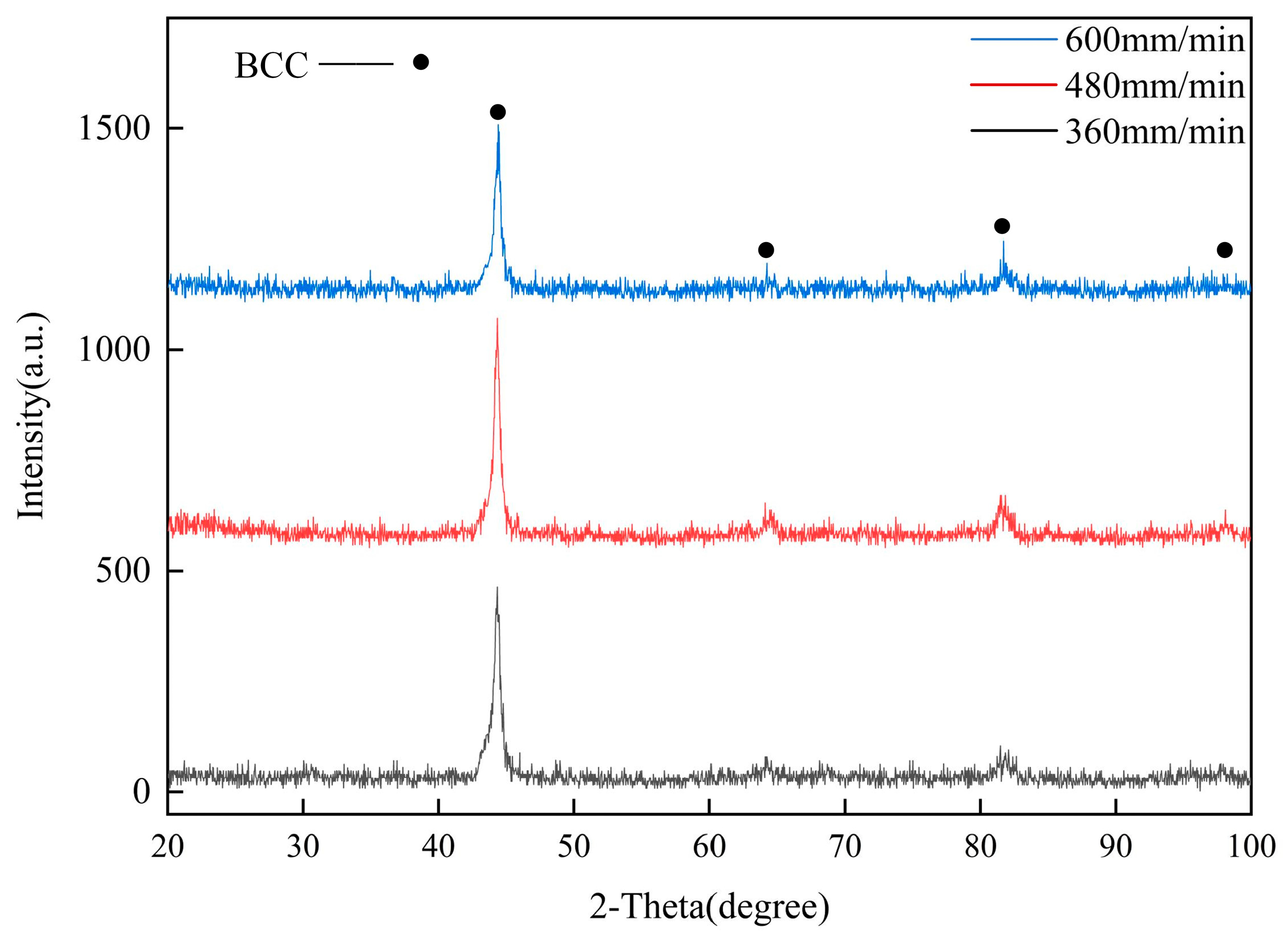
3.1. Phase Analysis
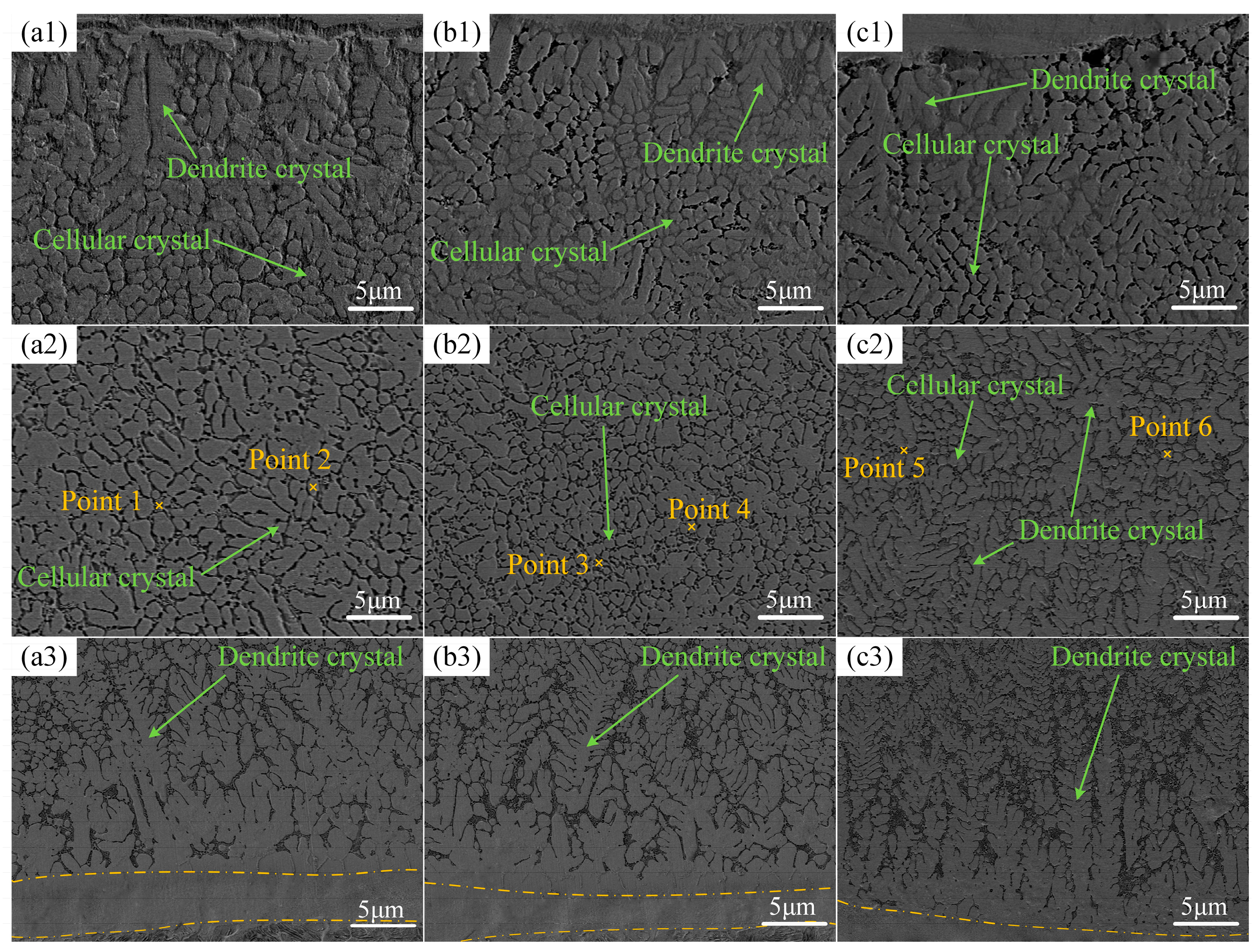
3.2. Microstructure Analysis
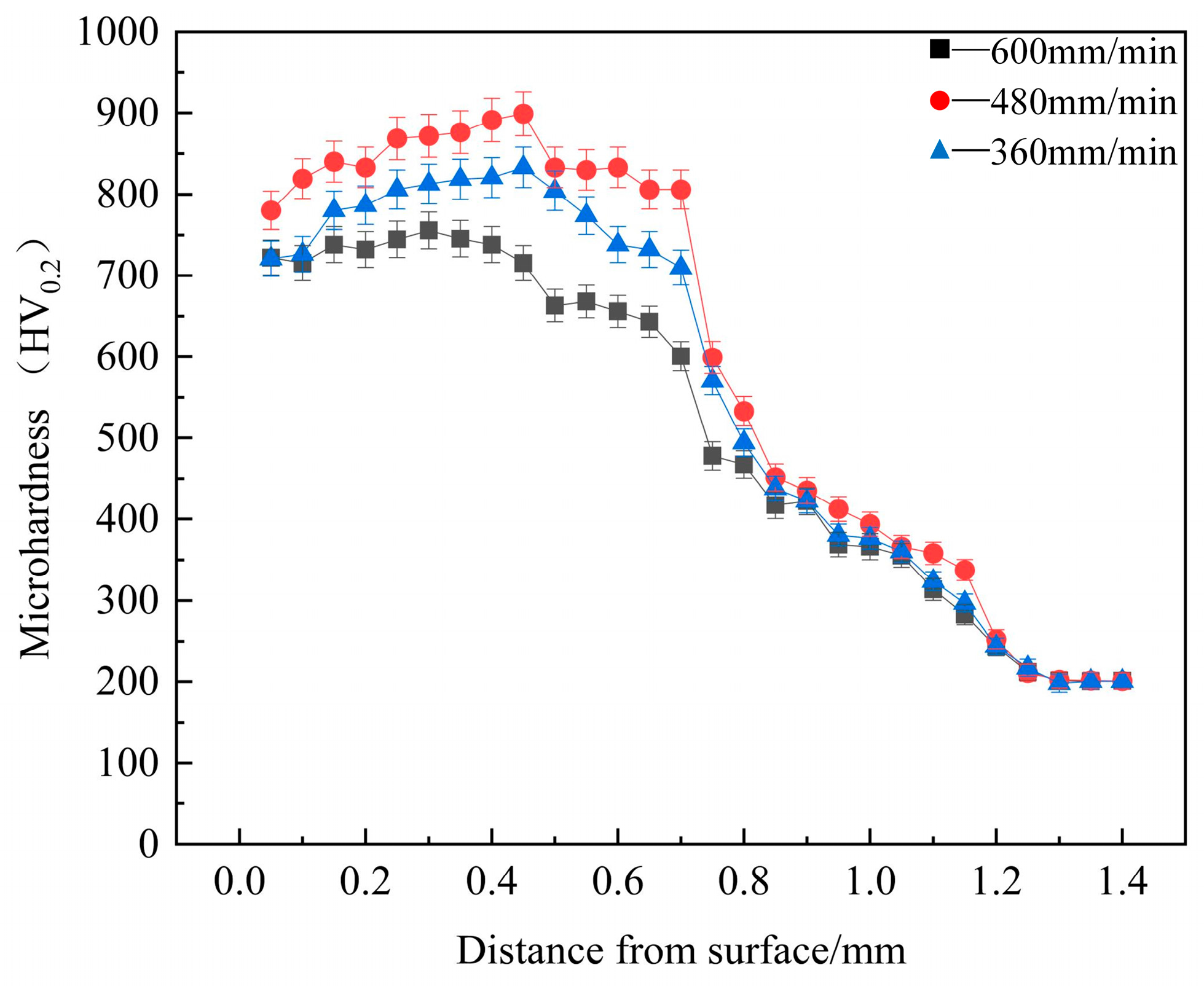
3.3. Microhardness Analysis
3.4. Wear Resistance Analysis
4. Conclusions
- (1)
- The coatings consist of a BCC phase, with lattice distortion occurring in the phase structure, leading to a high dislocation density. The structure of the bonding zone is planar crystal, while the coating’s microstructure comprises dendrite crystals and cellular crystals.
- (2)
- Through the combined effects of dislocation, fine-grain, and solid solution strengthening, the microhardness of the coatings at various scanning speeds is 3.5 to 4.2 times greater than that of the substrate.
- (3)
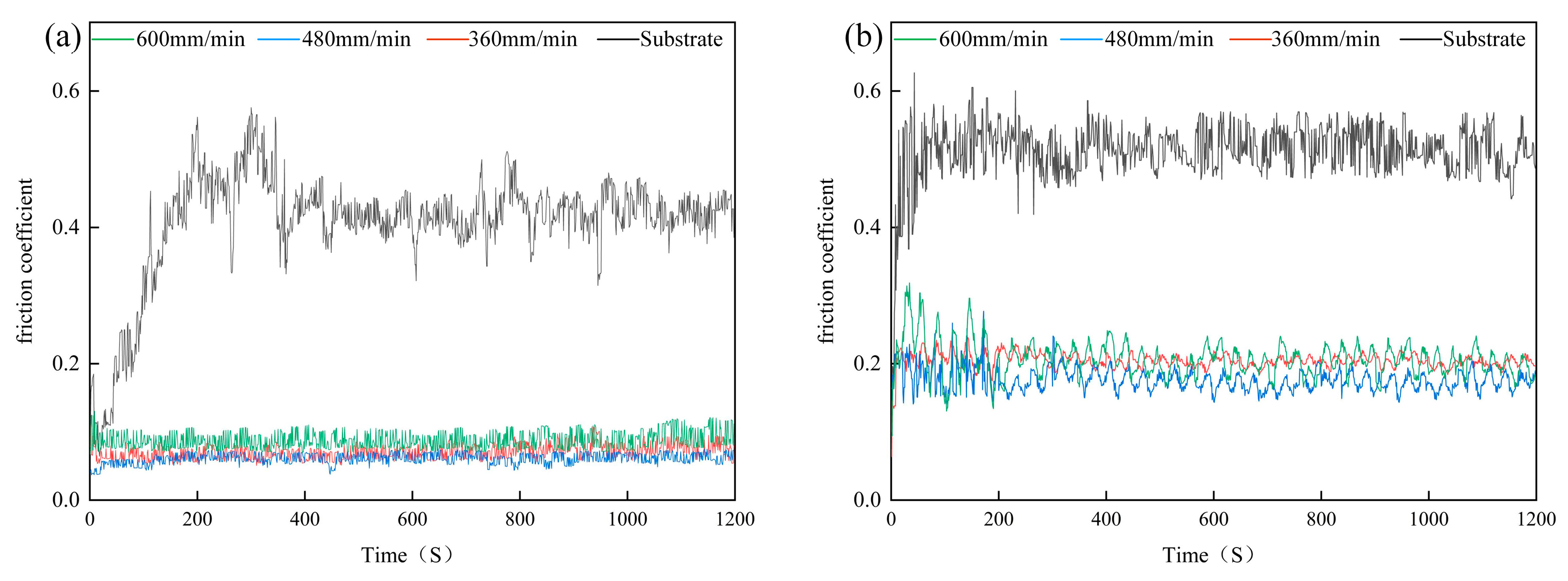
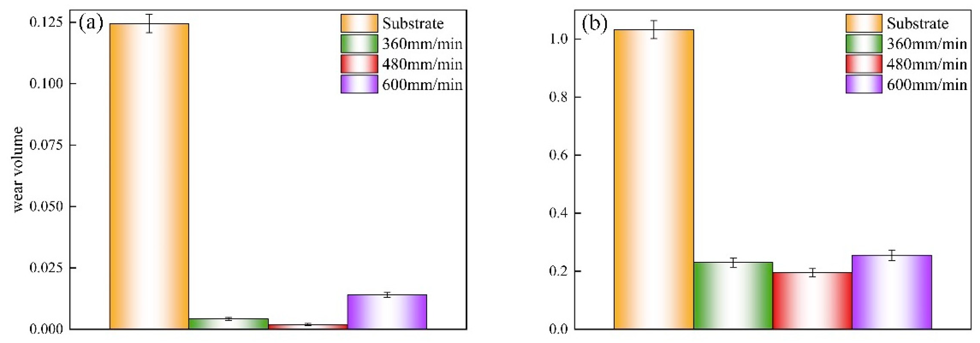
- The coatings possess lower average friction coefficients than that of the substrate at different temperatures, and accordingly, the wear volume of the coatings is also lower. Compared to the substrate, the coatings undergo slight abrasive wear, adhesive wear, and oxidative wear at both room temperature and 823 K. In contrast, the substrate undergoes severe abrasive wear, adhesive wear, oxidative wear, and even fatigue wear.
- (4)
- At a scanning speed of 480 mm/min, the coating exhibits the best performance, with the highest dislocation density compared to other coatings. The coating has the finest grain and the highest average microhardness (842 HV0.2), which is 4.2 times that of the substrate (200 HV0.2). The coating also has the lowest friction coefficient and the smallest wear volume, which is approximately 640% less than that of the substrate.
Author Contributions
Funding
Institutional Review Board Statement
Informed Consent Statement
Data Availability Statement
Acknowledgments
Conflicts of Interest
References
- Wang, J.F.; Li, J.Q.; Wang, L.Z.; Chen, C.Y.; Wang, X.; Zhao, F. Study on modification of primary carbides and improvement of properties in H13 steel by CeO2 nanoparticles addition. J. Mater. Res. Technol. 2023, 27, 7685–7694. [Google Scholar] [CrossRef]
- Ding, H.G.; Liu, T.; Wei, J.B.; Chen, L.L.; Cao, F.Y.; Zhang, B.S.; Luo, R.; Cheng, X.N. Microstructure and tempering softening mechanism of modified H13 steel with the addition of Tungsten, Molybdenum, and lowering of Chromium. Mater. Design 2022, 224, 111317. [Google Scholar] [CrossRef]
- Li, C.D.; Qiu, F.; Yang, H.Y.; Chang, F.; Li, T.Y.; Zhang, H.; Jiang, Q.C. Role and mechanism of innovative addition process of trace nano-TiCp in microstructure manipulation and significant mechanical properties enhancement of H13 steels. J. Mater. Proce. Tech. 2023, 311, 117819. [Google Scholar] [CrossRef]
- Berrais, A.; Boudebane, A.; Labaiz, M.; Montagne, A.; Lemboub, S.; Touhami, M.Z.; Ourdjini, A. Analysis of wear of a nitrided AISI H13 hot work tool steel in an aluminum hot extrusion process. Wear 2023, 514–515, 204587. [Google Scholar] [CrossRef]
- Wang, Y.J.; Jia, Z.; Ji, J.J.; Wei, B.L.; Heng, Y.B.; Liu, D.X. Determining the wear behavior of H13 steel die during the extrusion process of pure nickel. Eng. Fail. Anal. 2022, 134, 106053. [Google Scholar] [CrossRef]
- Ding, H.G.; Cheng, X.N.; Liu, T.; Cao, F.Y.; Chen, L.L.; Luo, R.; Zhang, Y.X.; Zhang, B.S. Microstructure and high-temperature tensile behavior of spray-formed modified 2000MPa H13 hot work die steel with 0.5wt % carbon. Mater. Sci. Eng. A 2022, 842, 143102. [Google Scholar] [CrossRef]
- Zou, J.X.; Wu, A.M.; Dong, C.; Hao, S.Z.; Liu, Z.M.; Ma, H.T. Oxidation protection of AISI H13 steel by high current pulsed electron beam treatment. Surf. Coat. Technol. 2004, 183, 261–267. [Google Scholar] [CrossRef]
- Neto, N.D.C.; Brune, R.; Luo, A.A.; Brancaleon, P.; Korenyi-both, A.L.; Midson, S.P.; Kaufman, M.J. Towards lube-free aluminum high pressure die casting using duplex AlCrN physical vapor deposition coatings. J. Mater. Res. Technol. 2023, 24, 7409–7426. [Google Scholar] [CrossRef]
- Shakib, S.E.; Babakhani, A.; Torbati, M.K. Nanomechanical assessment of tribological behavior of TiN/TiCN multi-layer hard coatings deposited by physical vapor deposition. J. Mater. Res. Technol. 2023, 25, 1344–1354. [Google Scholar] [CrossRef]
- Farid, M.A.; Amir, A.Z.; Maryam, A.Z.; Narguess, N.; Ramin, A. Plasma-enhanced chemical vapor deposition of TiB2 and TiBN hard coatings using BBr3. Tribol. Int. 2023, 179, 108137. [Google Scholar]
- Arulvel, S.; Winfred, R.D.D.; Akshat, J.; Jayakrishna, K.; Mridul, S. Laser processing techniques for surface property enhancement: Focus on material advancement. Surf. Interfaces 2023, 42, 103293. [Google Scholar]
- Li, Y.F.; Zhang, J.; Huang, X.H.; Liu, J.; Deng, L.J.; Han, P.Y. Influence of laser power on microstructure evolution and properties of laser cladded FeNiCoCrMo HEA coatings. Mater. Today Commun. 2023, 35, 105615. [Google Scholar] [CrossRef]
- Cai, Y.C.; Chen, Y.; Manladan, S.M.; Zhen, L.; Gao, F.; Li, L. Influence of dilution rate on the microstructure and properties of FeCrCoNi high-entropy alloy coating. Mater. Design 2018, 142, 124–137. [Google Scholar] [CrossRef]
- Xu, J.F.; Zhou, L.; Ma, G.Z.; Li, G.L.; Zhao, H.C.; Wang, H.D. Microstructure and excellent arc ablation resistance of Ni–8Al coating on copper substrate by high-speed laser cladding. J. Mater. Res. Technol. 2024, 31, 606–617. [Google Scholar] [CrossRef]
- He, H.T.; Fang, J.X.; Wang, J.X.; Sun, T.; Yang, Z.; Ma, B.; Chen, H.T.; Wen, M. Carbide-reinforced Re0.1Hf0.25NbTaW0.4 refractory high-entropy alloy with excellent room and elevated temperature mechanical properties. Int. J. Refract. Met. Hard Mater. 2023, 116, 106349. [Google Scholar] [CrossRef]
- Guo, Q.W.; Hou, H.; Pan, Y.; Pei, X.L.; Song, Z.; Liaw, P.K.; Zhao, Y.H. Hardening-softening of Al0.3CoCrFeNi high-entropy alloy under nanoindentation. Mater. Design 2023, 231, 112050. [Google Scholar] [CrossRef]
- Guo, Q.W.; Hou, H.; Wang, K.L.; Li, M.X.; Liaw, P.K.; Zhao, Y.H. Coalescence of Al0.3CoCrFeNi polycrystalline high-entropy alloy in hot-pressed sintering: A molecular dynamics and phase-field study. Npj Comput. Mater. 2023, 9, 185. [Google Scholar] [CrossRef]
- Li, Y.T.; Jiang, X.; Wang, X.T.; Leng, Y.X. Integration of hardness and toughness in (CuNiTiNbCr)Nx high entropy films through nitrogen-induced nanocomposite structure. Scr. Mater. 2024, 238, 115763. [Google Scholar] [CrossRef]
- Li, Y.T.; Chen, X.M.; Zeng, X.K.; Liu, M.; Jiang, X.; Leng, Y.X. Hard yet tough and self-lubricating (CuNiTiNbCr)Cx high-entropy nanocomposite films: Effects of carbon content on structure and properties. J. Mater. Res. Technol. 2024, 173, 20–30. [Google Scholar]
- Cao, S.L.; Liang, J.; Zhou, J.S.; Wang, L.G. Microstructure evolution and wear resistance of in-situ nanoparticles rein forcing Fe-based amorphous composite coatings. Surf. Interfaces 2020, 21, 100652. [Google Scholar] [CrossRef]
- Pang, X.M.; Jiang, J.X.; Zhao, D.Y.; Zhou, J.X. Study of wide temperature range and hard protective La2O3 doped cermet based single-layer solar selective absorbing coating by laser cladding. Surf. Interfaces 2021, 27, 101544. [Google Scholar] [CrossRef]
- Xue, K.N.; Lu, H.F.; Luo, K.Y.; Cui, C.Y.; Yao, J.H.; Xing, F.; Lu, J.Z. Effects of Ni25 transitional layer on microstructural evolution and wear property of laser clad composite coating on H13 tool steel. Surf. Coat. Technol. 2020, 402, 126488. [Google Scholar] [CrossRef]
- Lu, H.F.; Xue, K.N.; Xu, X.; Luo, K.Y.; Xing, F.; Yao, J.H.; Lu, J.Z. Effects of laser shock peening on microstructural evolution and wear property of laser hybrid remanufactured Ni25/Fe104 coating on H13 tool steel. J. Mater. Process. Technol. 2021, 291, 117016. [Google Scholar] [CrossRef]
- Lu, J.Z.; Xue, K.N.; Lu, H.F.; Xing, F.; Luo, K.Y. Laser shock wave-induced wear property improvement and formation mechanism of laser cladding Ni25 coating on H13 tool steel. J. Mater. Process. Technol. 2021, 296, 117202. [Google Scholar] [CrossRef]
- Rajeev, G.P.; Kamaraj, M.; Srinivasa, R.B. Hardfacing of AISI H13 tool steel with Stellite 21 alloy using cold metal transfer welding process. Surf. Coat. Technol. 2017, 326, 63–71. [Google Scholar]
- Debapriya, P.K.; Gopinath, M.; Ashish, K.N. Effect of scan strategy and heat input on the shear strength of laser cladded Stellite 21 layers on AISI H13 tool steel in as-deposited and heat treated conditions. Surf. Coat. Technol. 2020, 384, 125331. [Google Scholar]
- Wang, G.S.; Fan, G.H.; Geng, L.; Hu, W.; Huang, Y.D. Microstructure evolution and mechanical properties of TiB2/Cu composites processed by equal channel angular pressing at elevated temperature. Mater. Sci. Eng. A 2013, 571, 144–149. [Google Scholar] [CrossRef]
- Tran, V.N.; Yang, S.; Phung, T.A. Microstructure and properties of Cu/TiB2 wear resistance composite coating on H13 steel prepared by in-situ laser cladding. Opt. Laser Technol. 2018, 108, 480–486. [Google Scholar] [CrossRef]
- Zhao, Z.Y.; Zheng, K.Y.; Yu, X.H.; Wang, L.J.; Yao, S.Y.; Qi, Q. Effect of particles size of TiC on oxidation resistance of in-situ TiC/Ni composite. Heliyon 2023, 9, 18220. [Google Scholar] [CrossRef]
- Wang, G.Y.; Zhang, J.Z.; Shu, R.Y.; Yang, S. High temperature wear resistance and thermal fatigue behavior of Stellite-6/WC coatings produced by laser cladding with Co-coated WC powder. Int. J. Refract. Met. Hard Mater. 2019, 81, 63–70. [Google Scholar] [CrossRef]
- Shu, F.Y.; Zhang, B.L.; Liu, T.; Sui, S.H.; Liu, Y.X.; He, P.; Liu, B.; Xu, B.S. Effects of laser power on microstructure and properties of laser cladded CoCrBFeNiSi high-entropy alloy amorphous coatings. Surf. Coat. Technol. 2019, 358, 667–675. [Google Scholar] [CrossRef]
- Li, Z.T.; Jing, C.N.; Feng, Y.; Wu, Z.L.; Lin, T.; Zhao, J.R. Microstructure evolution and properties of laser cladding Nb containing eutectic high entropy alloys. Int. J. Refract. Met. Hard Mater. 2023, 110, 105992. [Google Scholar] [CrossRef]
- Shi, F.K.; Zhang, Q.K.; Xu, C.; Hu, F.Q.; Yang, L.J.; Zheng, B.Z.; Song, Z.L. In-situ synthesis of NiCoCrMnFe high entropy alloy coating by laser cladding. Opt. Laser Technol. 2022, 151, 108020. [Google Scholar] [CrossRef]
- Guo, Y.Q.; Guo, Z.H.; Li, Z.Y.; He, R.; Wang, G.P. Effect of laser energy densities on the phase composition change in laser-cladded AlCoCrNbMo high-entropy alloy coatings. Mater. Today Commun. 2023, 37, 107152. [Google Scholar] [CrossRef]
- Takebayashi, S.; Kunieda, T.; Yoshinaga, N.; Ushioda, K.; Ogata, S. Comparison of the Dislocation Density in Martensitic Steels Evaluated by Some X-ray Diffraction Methods. ISIJ Int. 2010, 50, 875–882. [Google Scholar] [CrossRef]
- Liu, X.T.; Lei, W.B.; Ma, L.J.; Liu, J.; Liu, J.L.; Cui, J.Z. On the microstructures, phase assemblages and properties of Al0.5CoCrCuFeNiSix high-entropy alloys. J. Alloys Compd. 2015, 630, 151. [Google Scholar] [CrossRef]
- Zhu, J.M.; Fu, H.M.; Zhang, H.F.; Wang, A.M.; Li, H.; Hu, Z.Q. Synthesis and properties of multiprincipal component AlCoCrFeNiSix alloys. Mater. Sci. Eng. A 2010, 527, 7210–7214. [Google Scholar] [CrossRef]
- Salim, E.T.; Ismail, R.A.; Halbos, H.T. Growth of Nb2O5 film using hydrothermal method: Effect of Nb concentration on physical properties. Mater. Res. Express 2019, 6, 116429. [Google Scholar] [CrossRef]
- Hemmati, I.; Ocelík, V.; De Hosson, J.T.M. Microstructural characterization of AISI 431 martensitic stainless steel laser-deposited coatings. J. Mater. Sci. 2011, 46, 3405–3414. [Google Scholar] [CrossRef]
- Cui, Y. Evolution Mechanism of Microstructure and Properties of the FeCoCrNiMnAl High-entropy Laser Cladding Layer. Doctoral Dissertation, Tianjin University, Tianjin, China, 23 May 2021. [Google Scholar]


| Element | C | Si | Mn | Cr | Mo | V | S | P | Fe |
|---|---|---|---|---|---|---|---|---|---|
| wt.% | 0.32–0.45 | 0.80–1.20 | 0.20–0.50 | 4.75–5.50 | 1.10–1.75 | 0.80–1.20 | ≤0.03 | ≤0.03 | Bal. |
| High-Entropy Alloy | Fe | Cr | Ni | Ti | Zr |
|---|---|---|---|---|---|
| wt.% | 18.27 | 17.01 | 19.21 | 15.66 | 29.85 |
| Laser Power | Scanning Speed | Overlap Rate | Spot Diameter | Shielding Gas | Shielding Gas Flow |
|---|---|---|---|---|---|
| 1400 W | 360 mm/min 480 mm/min 600 mm/min | 30% | 3 mm | argon | 5 L/h |
| Coating | a (Å) | ε | ξ | ρ (cm−2) |
|---|---|---|---|---|
| 360 mm/min | 2.887 | 3.825 × 10⁻³ | 2.2511 × 10⁻³ | 2.30 × 10¹¹ |
| 480 mm/min | 2.890 | 4.868 × 10⁻³ | 2.4722 × 10⁻³ | 2.35 × 10¹¹ |
| 600 mm/min | 2.8835 | 2.6078 × 10⁻³ | 1.5126 × 10⁻³ | 1.50 × 10¹¹ |
| Coating | θ(°) | β |
|---|---|---|
| 360 mm/min | 44.338 | 0.432 |
| 64.477 | 0.32 | |
| 81.487 | 0.351 | |
| 98.089 | 0.283 | |
| 480 mm/min | 44.293 | 0.239 |
| 64.221 | 0.304 | |
| 81.839 | 0.145 | |
| 97.698 | 0.271 | |
| 600 mm/min | 44.393 | 0.335 |
| 64.204 | 0.288 | |
| 81.716 | 0.463 | |
| 97.959 | 0.202 |
| Points | Fe | Cr | Ni | Ti | Zr |
|---|---|---|---|---|---|
| 1 | 54.3 | 11.4 | 12.3 | 5.8 | 16.2 |
| 2 | 62.9 | 15.4 | 9.5 | 3.3 | 8.9 |
| 3 | 53.6 | 11.7 | 11.6 | 5.1 | 18.0 |
| 4 | 63.8 | 16.4 | 8.0 | 3.3 | 8.5 |
| 5 | 54.6 | 10.5 | 12.1 | 5.8 | 17.0 |
| 6 | 65.5 | 15.2 | 7.7 | 3.2 | 8.4 |
| Temperature | Substrate | 360 mm/min | 480 mm/min | 600 mm/min |
|---|---|---|---|---|
| Room temperature | 0.42 | 0.07 | 0.06 | 0.09 |
| 823 K | 0.52 | 0.20 | 0.17 | 0.21 |
| Alloy | Temperatures | Fe | Cr | Ni | Ti | Zr | O | C | Si | V |
|---|---|---|---|---|---|---|---|---|---|---|
| 360 mm/min | room temperature | 35.71 | 15.47 | 17.35 | 8.52 | 19.05 | 3.90 | - | - | - |
| 823 K | 44.20 | 11.31 | 10.34 | 5.44 | 13.04 | 15.67 | - | - | - | |
| 480 mm/min | room temperature | 38.79 | 15.89 | 16.77 | 8.06 | 17.62 | 3.87 | - | - | - |
| 823 K | 41.53 | 11.39 | 11.34 | 6.29 | 15.06 | 14.39 | - | - | - | |
| 600 mm/min | room temperature | 35.62 | 15.23 | 16.85 | 8.27 | 19.12 | 4.91 | - | - | - |
| 823 K | 41.29 | 11.03 | 11.57 | 6.28 | 15.58 | 14.25 | - | - | - | |
| Substrate | room temperature | 69.13 | 3.40 | - | - | - | 8.00 | 13.36 | 0.49 | 0.62 |
| 823 K | 69.59 | 3.98 | - | - | - | 21.39 | 3.75 | 0.75 | 0.84 |
Disclaimer/Publisher’s Note: The statements, opinions and data contained in all publications are solely those of the individual author(s) and contributor(s) and not of MDPI and/or the editor(s). MDPI and/or the editor(s) disclaim responsibility for any injury to people or property resulting from any ideas, methods, instructions or products referred to in the content. |
© 2024 by the authors. Licensee MDPI, Basel, Switzerland. This article is an open access article distributed under the terms and conditions of the Creative Commons Attribution (CC BY) license (https://creativecommons.org/licenses/by/4.0/).
Share and Cite
Gao, Y.; Bai, S.; Jiang, S.; Lu, P.; Zhang, D.; Jie, M.; Liu, Y. Effect of the Laser Cladding Parameters on Microstructure and Elevated Temperature Wear of FeCrNiTiZr Coatings. Materials 2024, 17, 4444. https://doi.org/10.3390/ma17184444
Gao Y, Bai S, Jiang S, Lu P, Zhang D, Jie M, Liu Y. Effect of the Laser Cladding Parameters on Microstructure and Elevated Temperature Wear of FeCrNiTiZr Coatings. Materials. 2024; 17(18):4444. https://doi.org/10.3390/ma17184444
Chicago/Turabian StyleGao, Yali, Sicheng Bai, Shan Jiang, Pengyong Lu, Dongdong Zhang, Meng Jie, and Yu Liu. 2024. "Effect of the Laser Cladding Parameters on Microstructure and Elevated Temperature Wear of FeCrNiTiZr Coatings" Materials 17, no. 18: 4444. https://doi.org/10.3390/ma17184444
APA StyleGao, Y., Bai, S., Jiang, S., Lu, P., Zhang, D., Jie, M., & Liu, Y. (2024). Effect of the Laser Cladding Parameters on Microstructure and Elevated Temperature Wear of FeCrNiTiZr Coatings. Materials, 17(18), 4444. https://doi.org/10.3390/ma17184444