Article

Short Fatigue-Crack Growth from Crack-like Defects under Completely Reversed Loading Predicted Based on Cyclic R-Curve

1
School of Engineering, Nagoya University, 4-7-203 Ketsuzen-cho, Nishinomiya 662-0037, Japan
2
Department of Mechanical Engineering and Materials Science, Yokohama National University, 79-5 Tokiwadai, Hodogaya-ku, Yokohama 240-8501, Japan
*
Author to whom correspondence should be addressed.
Materials 2024, 17(18), 4484; https://doi.org/10.3390/ma17184484
Submission received: 19 August 2024 / Revised: 6 September 2024 / Accepted: 10 September 2024 / Published: 12 September 2024

Abstract

:
Understanding short fatigue-crack propagation behavior is inevitable in the defect-tolerant design of structures. Short cracks propagate differently from long cracks, and the amount of crack closure plays a key role in the propagation behavior of short cracks. In the present paper, the buildup of fatigue-crack closure due to plasticity with crack extension from crack-like defects is simulated with a modified strip yield model, which leaves plastic stretch in the wake of the advancing crack. Crack-like defects are assumed to be closure-free and do not close even under compression. The effect of the size of crack-like defects on the growth and arrest of short cracks was systematically investigated and the cyclic R-curve derived. The cyclic R-curve determined under constant amplitude loading of multiple specimens is confirmed to be independent of the initial defect length. Load-shedding and ΔK-constant loading tests are employed to extend the cyclic R-curve beyond the fatigue limit determined under constant amplitude loading. The initiation stage of cracks is taken into account in R-curves when applied to smooth specimens.

1. Introduction

In order to guarantee structural integrity, design engineers have been facing challenges in fatigue strength assessment of steel structural components, which usually contain imperfections. The determination of the tolerance level is a primary issue. Fatigue cracks always start at the spot of stress concentration, such as notches or defects, in structural components, and subsequent crack propagation results in the fracture of structures. Classical design of notch fatigue is based on the fatigue strength reduction factor, which is dependent on the size of the defects even if defects have the same stress concentration factor. When the defect size is very small, the fatigue strength of defected components is not reduced. On the other hand, as the size becomes larger, the fatigue strength is reduced by the amount of stress concentration factor or the stress intensity factor. There is an urgent need to establish a defect-resistant design methodology that takes defect size effects into account.
Understanding short fatigue-crack propagation behavior is integral to defect-tolerant design. The fatigue strength of components with small defects is determined by crack propagation, but not by crack initiation. In steel components subjected to stress amplitude below the fatigue limit, nonpropagating short cracks have been observed near defects [1,2,3]. Even in smooth specimens, nonpropagating small cracks have been observed below the fatigue limit [4,5,6,7,8], and the propagation condition controls the fatigue limit of smooth specimens.
Previously proposed models for predicting the initial deceleration or arrest of short cracks in notch fatigue are classified into two groups. One is based on the decrease of the amount of plasticity with distance from the notch tip, which induces crack deceleration or arrest as proposed by Smith et al. [9] and Haddad et al. [10]. The other is based on fatigue-crack closure. The buildup of crack closure with crack extension induces the decrease of the effective range of stress intensity factor (SIF), ΔKeff, resulting in deceleration or arrest of crack propagation. Tanaka et al. [11] showed that the ΔKeff value was a controlling parameter for short crack growth in near-threshold regime of notch fatigue. Under the situation of excess notch plasticity, Nishikawa et al. [12] reported that all the growth data of short cracks were successfully correlated with long cracks using the ΔKeff parameter, even though the amount of crack opening was enhanced in the notch-plastic zone.
For smooth specimen fatigue, Abdel-Raouf et al. [13] proposed that surface strain concentration was the main reason for nonpropagating cracks observed below the fatigue limit. Miller [14] proposed a microstructural barrier, such as a grain boundary, is the main cause for the arrest of small cracks. Akiniwa et al. [15] showed both microstructural barrier and crack closure could cause the nonpropagation of small cracks below the fatigue limit in smooth specimens.
To predict the fatigue threshold of components with notches or defects, Tanaka et al. [16] first proposed the cyclic R-curve method assuming the buildup of crack closure as the main mechanism of increase in resistance against crack growth. Cyclic R-curves are expressed as the relation between the threshold SIF range ΔKth and the amount of crack extension Δa, where ΔKth is an increasing function of Δa. The R-curve method was successfully applied to predict the effects of notch geometry and precrack length on fatigue thresholds [17,18]. Later, several investigators [19,20,21,22,23,24] used the concept of cyclic R-curve in order to explain their fatigue threshold results of components with defects. The state of the art of the cyclic R-curve method is described in recent reviews [25,26]. In relation to the R-curve method, Chapetti [27,28] proposed a different method to predict short crack growth behavior. He derived the relation between ΔKth and crack length from the experimental data under the assumption that ΔKth was a single-valued increasing function of the current length, independent of the initial size of crack-like defects or precracks. His proposal is not necessarily based on crack closure as a main mechanism of increasing material resistance to crack growth.
Few data on crack closure of short cracks have been published because experimental measurements are very hard to conduct. Contrary to experimental measurements, computer simulation of crack closure enables a systematic examination of the effects of defect size, yield stress, and applied stress on crack closure. Useful guidelines to examine experimental data will be provided by the simulation. Near the threshold in a nonaggressive environment, the main mechanisms of crack closure are plasticity-induced crack closure (PICC) and roughness-induced crack closure (RICC) [29]. With respect to RICC, several models have been proposed, but they are not yet available to predict quantitatively small crack growth behavior. On the other hand, for PICC, Budiansky and Hutchinson [30] proposed a strip yield model of Dugdale type [31] leaving residual stretches on crack wake faces and analyzed steady state growth of long cracks. Based on the modified strip yield model, Newman [32] developed a numerical simulation method to compute the development of PICC with crack extension. Toyosada et al. [33] included elastic deformation in Newman’s rigid plastic yield strips. A modified strip yield model is also applied to predict the crack propagation rate based on calculated ΔKeff [32,33] or combined with the damage accumulation model [34].
In our preceding papers [35,36,37], a modified strip yield model was applied to fatigue-crack growth from crack-like defects or precracks with various sizes under completely reversed cyclic loading. Crack-like defects are called precracks in the present paper. The model was two-dimensional, and the stress state was plane stress. The precracks examined are two types: open precracks (Type I) and closed precracks (Type II). Open precracks are those made by cyclic compression precracking and may also represent material defects such as pores or drilled holes. The initial crack faces do not touch each other even under the maximum compression. Examples of closed precracks are natural cracks made by conventional fatigue, followed by annealing for residual stress relief. They may have no initial clearance between crack faces, so the crack faces may touch each other under compression. According to the results of our preceding paper [36], open precracks give lower opening stress than closed precracks under any stress amplitude, so the ΔKeff value for open cracks is larger than that for closed cracks. The prediction of fatigue thresholds for open precracks is conservative, giving a lower fatigue limit and shorter fatigue life.
In the present paper, only PICC buildup from open precracks will be dealt with in order to obtain conservative estimation of steel structural components. The effect of defect size on fatigue thresholds is systematically examined. The cyclic R-curve is determined under constant amplitude loading of multiple specimens. Load-shedding and ΔK-constant loading tests are employed to extend the cyclic R-curve beyond the fatigue limit of precracked specimens determined under constant amplitude loading. In order to apply the R-curve method to smooth specimen fatigue, the crack initiation stage is taken into account in the R-curve method.

2. Simulation Procedure

A crack is extending straight from both ends of a crack-like defect or precrack in an infinite plate under a constant amplitude of completely reversed loading applied perpendicular to the defect. The assumed stress state is plane stress, and the loading mode of cracks is mode I. Plastic deformation ahead of crack tips is modeled by a yield strip, which is elastic perfectly plastic. The wake faces of advancing cracks have residual stretches, while the faces of precracks have no residual stretch. In the simulation, an initial clearance of 0.1 mm is attached to precracks to avoid crack face contact. The influence of the clearance of precracks on the stress distribution is not considered. For precracked specimens, the start of crack extension is called crack initiation in the present paper.
The simulation method used in the present paper is basically the same as the one used in the preceding papers [35,36]. The essence of the method is summarized in Appendix A.
Simulated materials are structural steels whose Young’s modulus is 206 GPa and Poisson’s ratio is 0.30. The yield stress is 400 MPa. The half-length of a crack-like defect ranges from 0.01 to 100 mm, such as 0.01, 0.03, 0.05, 0.1, 0.3, 1, 3, 10, 30, and 100 mm.
The threshold value of the effective SIF range ΔKeffth is adopted as the threshold condition for crack growth. The reported values of steels are about 2~3 MPa m , independent of the material yield strength [11,16,17,18,25,26,38,39]. Using the unloading compliance method [40], Tanaka et al. measured the threshold range, ΔKeffth, of short fatigue cracks of several steels in various situations and reported values around 3 MPa m   [11,16,17,18,39]. They did not find any significant effect of R ratio on ΔKeffth.
The threshold value of ΔKth for long cracks at R ratios higher than 0.8 is expected to be equal to ΔKeffth. The reported values of ΔKth are between 2 and 3 MPa m for steels with the yield strength ranging from 300 to 1800 MPa [38,41]. Many investigators used compression precracking of notched specimens to produce closure-free precracks [19,20,22,23,24,25,26,42]. They interpreted the SIF range for crack initiation from precracks made by compression precracking as the intrinsic threshold value. For steels, their reported values are between 2 and 3 MPa m , which are close to the critical SIF value for generation of cyclic plastic deformation at the crack tip [43,44].
On the basis of the above consideration, we adopt the threshold value of ΔKeffth = 3 MPa m as the crack growth criterion in the present paper.

3. Fatigue Growth Threshold of Short Cracks from Precracks

3.1. Buildup of Crack Closure with Crack Extension

In simulation, the crack opening stress, σop, was determined as a function of the amount of crack extension from a precrack under R = −1. The relation between opening stress ratio Rop = σop/σmax and crack extension Δa changes with the applied maximum stress, σmax, relative to the yield stress. The main results are summarized as follows. For open precracks, the opening stress at crack initiation σop is equal to σmin and Rop = σop/σmax = R = −1. The opening stress initially shows a quick increase and then gradually approaches a steady state value as the crack extends longer. The steady state value of the opening stress ratio of long cracks decreases with increasing ratio of σmax to the yield stress.

3.2. Growth and Arrest of Short Cracks

The effective range of SIF, ΔKeff, over which crack tip is open is given by
Δ K eff = K max K op = K max 1 K op / K max = Δ K 1 R op / 1 R
where Kmax is the maximum SIF, Kop is the crack-tip opening SIF, and Rop = Kop/Kmax. The range of opening SIF, ΔKop, over which the crack tip is closed is expressed as
Δ K op = K op K min = σ op σ min π a = Δ σ op π a = Δ K Δ K eff
where K min = σ min π a is the minimum SIF. At crack initiation for open precracks, a = ai, Kop = Kmin and ΔKeff = ΔKeffth. The stress range for crack initiation, Δσw1, is
Δ σ w 1 = Δ K effth / π a i
where ai is the initial defect size.
After crack initiation under constant amplitude stress cycling, the applied stress intensity range, ΔK, increases with crack extension, and the effective stress intensity range, ΔKeff, initially decreases. Figure 1 shows the change in ΔKeff with crack extension Δa for an open precrack with the initial length of ai = 1 mm under seven stress ranges from 80 to 200 MPa with a step of 20 MPa. The crack is arrested when ΔKeff drops below ΔKeffth. The nonpropagating crack length Δanp becomes longer with increasing stress. For the case of ai = 1 mm, the fatigue limit for crack initiation is Δσw1 = 54 MPa, and that for fracture is Δσw2 = 159 MPa.
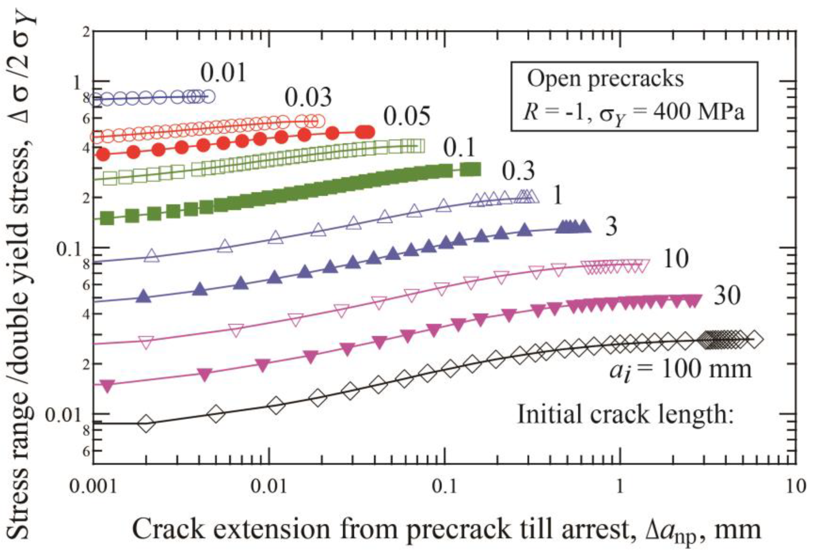
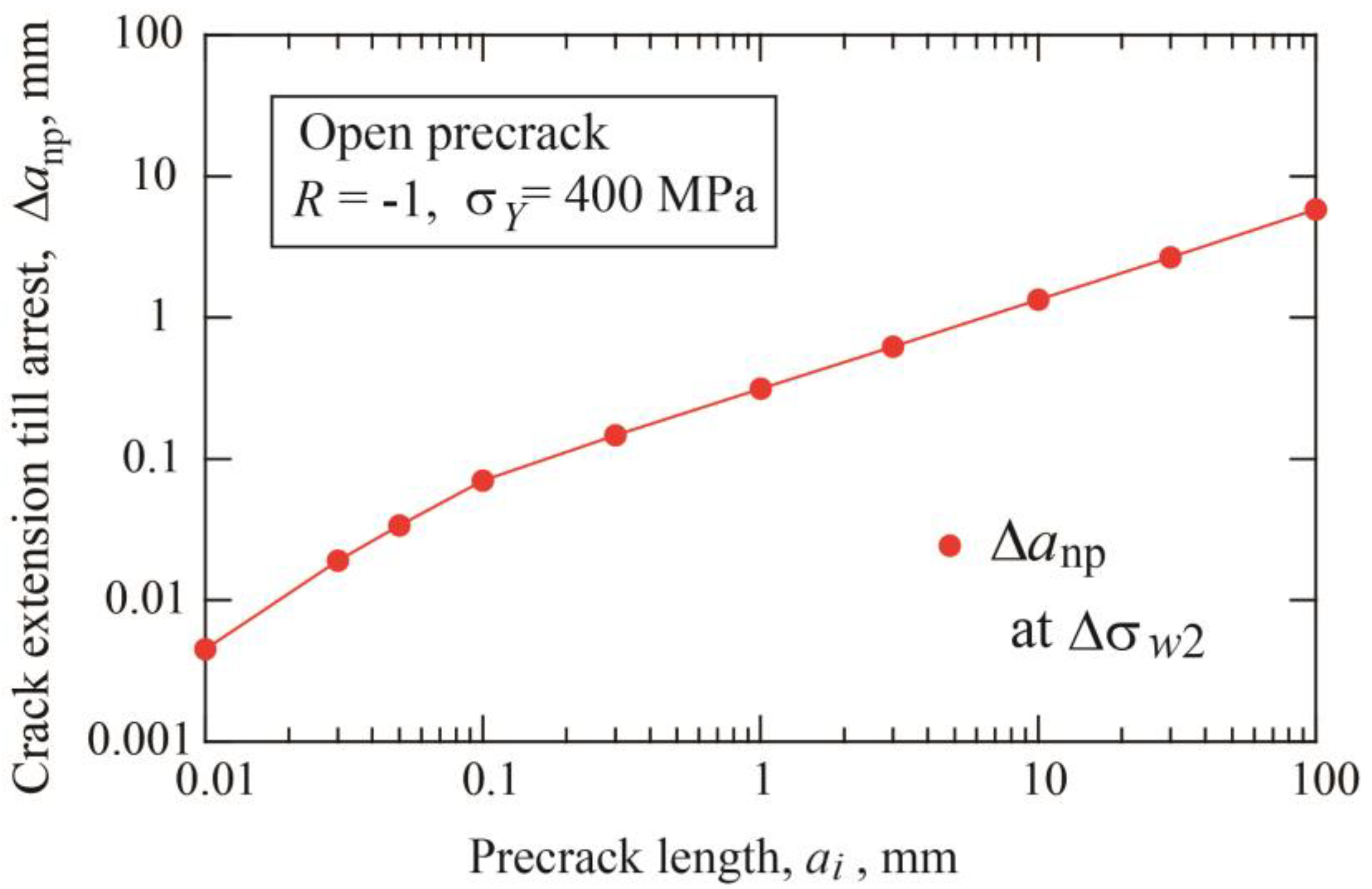
Figure 2 shows the change of the crack extension until arrest, Δanp, with the applied stress range relative to double yield stress, Δσ/2σY, for precracks with various lengths. For each precrack length, the data were obtained under constant amplitude loading of multiple specimens. The same results can be obtained by step-up amplitude loading of a single specimen [39]. For each precrack length, the stress range corresponding to the longest crack extension is the fatigue limit, Δσw2. Figure 3 indicates the change of the crack extension until arrest, Δa*np, at the fatigue limit Δσw2 with the precrack length. The Δa*np length increases with increasing precrack length. Under step-up amplitude loading or constant amplitude loading, the nonpropagating crack longer than Δa*np is not obtainable.

3.3. Effect of Precrack Length on Growth and Arrest of Short Cracks

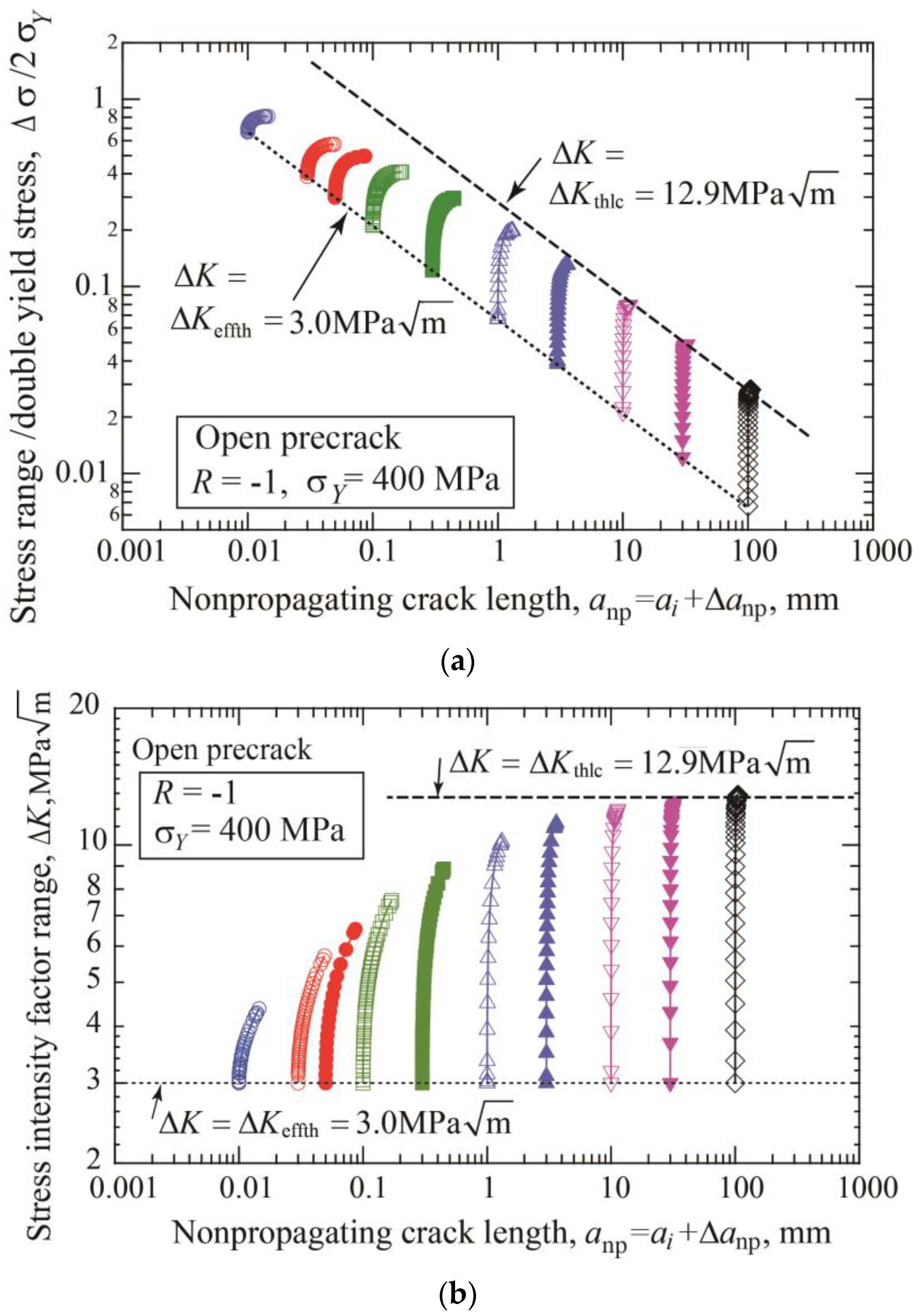
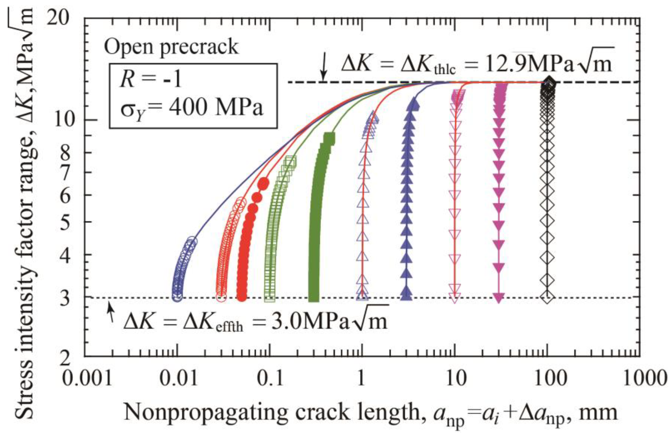
The fatigue threshold diagram of specimens with precracks is shown in Figure 4a. The threshold stress range divided by double yield stress is plotted against the nonpropagating crack length, which is the sum of the initial precrack length plus crack extension until arrest. The dotted line connecting the crack initiation data indicates the crack initiation threshold given by Equation (3). The dashed line corresponds to the threshold SIF range for long cracks ΔKthlc = 12.9 MPa m . Figure 4b is a different presentation of the fatigue threshold diagram, where the threshold SIF range is plotted against the nonpropagating crack length. The horizontal dotted line indicates the crack initiation condition, ΔK = ΔKeffth = 3 MPa m , and the dashed line means the threshold of ΔK = ΔKthlc = 12.9 MPa m . For each precrack length, the data points plotted between two lines correspond to crack extensions until self-arrest obtained under step-up amplitude loading. The ΔKth at the fatigue limit for fracture is nearly constant for crack lengths above 10 mm and shows a tendency to decrease with shorter crack lengths.

3.4. Fatigue Threshold Diagram

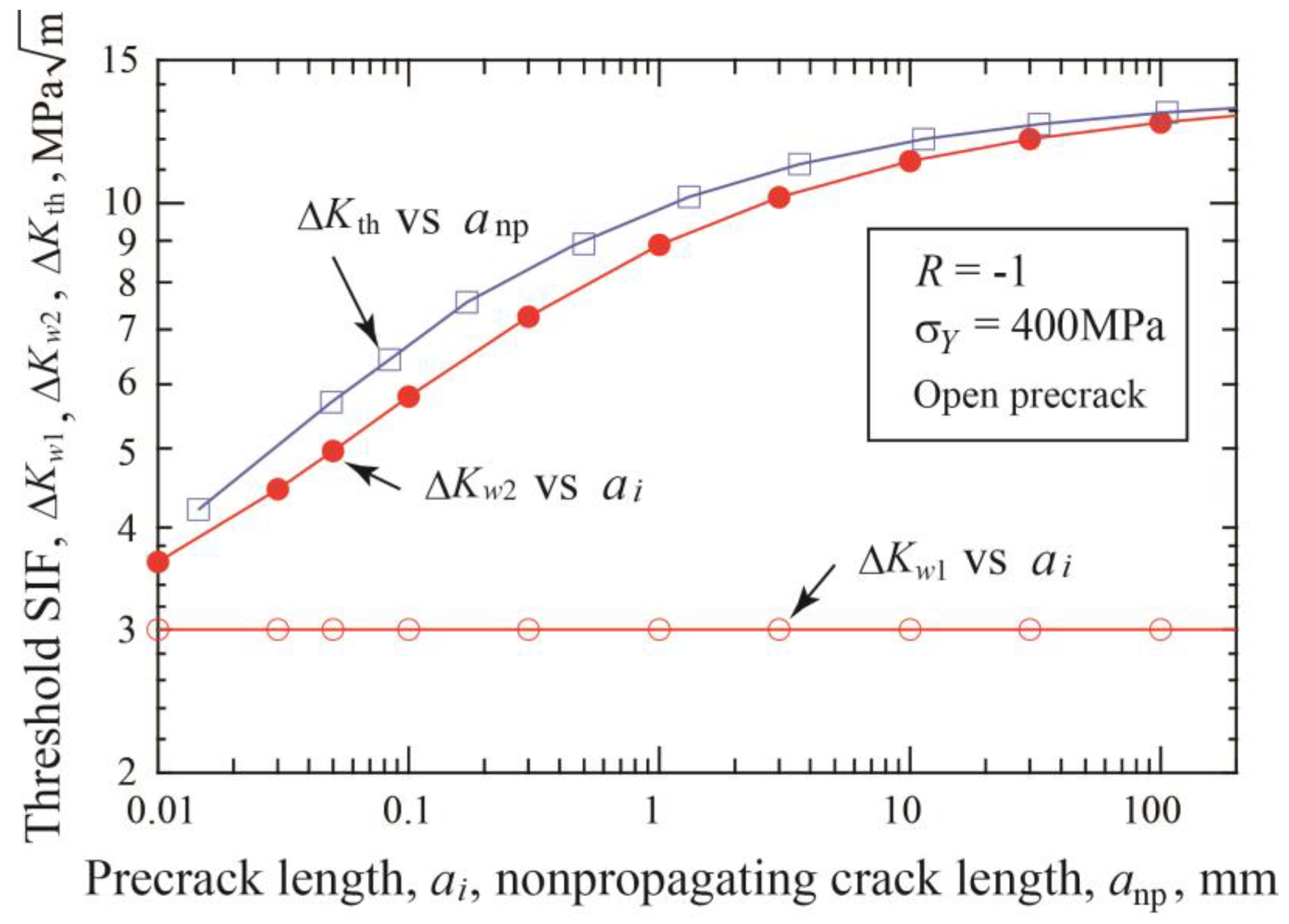
The fatigue threshold diagram of materials with defects is often called the Kitagawa–Takahashi diagram (K–T diagram), where the fatigue limit is in most cases plotted against the initial size of defects [45,46,47]. Likewise, the threshold stress ranges for crack initiation, Δσw1, and for fracture, Δσw2, obtained in the present simulation are plotted against the initial precrack length ai in Figure 5. Since the nonpropagating crack is formed, Δσw2 can be plotted at the nonpropagating crack length anp, which is the sum of the precrack length plus the crack extension, anp = ai + Δanp. The data with the red circles are shifted horizontally to those with the blue squares by the amount of crack extension in Figure 5. Here, the former is called Type A plot and the latter Type B plot. The Δσw1 value is given by Equation (3) and is the straight line in log-log diagram; there is no difference between Type A and B plots. The Δσw2 value has a horizontal shift between Type A and Type B plots and bends horizontally at shorter crack lengths in both plots.
The threshold values of SIF are calculated from Δσw1 and Δσw2, and initial precrack length ai by the following formulae:
Δ K w 1 = Δ σ w 1 π a i = Δ K effth
Δ K w 2 = Δ σ w 2 π a i
Both SIF values are plotted against the initial precrack size, ai, with the open and closed red circles in Figure 6. Since crack extension takes place until arrest, the true SIF value, ΔKth, at the threshold is larger than the ΔKw2 value and is expressed by
Δ K th = Δ σ w 2 π a i + Δ a np = Δ σ w 2 π a np
where anp is the nonpropagating crack length. In Figure 6, ΔKth is plotted with the open squares against anp. The difference between ΔKw2 and ΔKth is fairly large for short cracks and is much reduced for longer cracks.
In the K–T diagram, the threshold stress range, Δσw2, is usually plotted against the initial precrack length, or defect size, neglecting the crack extension until arrest, as shown with the Type A plot in Figure 5. On the other hand, there is some confusion in the plot of the threshold SIF against the defect size in published reports. Kitagawa et al. [45] determined the threshold SIF using a load-decreasing test. The threshold value was plotted against the crack length at arrest, not at the initial crack length, which means ΔKth plotted against anp = ai + Δanp. On the other hand, Murakami and Endo [48,49] calculated the threshold SIF from the initial defect area, which corresponds to ΔKw2 plotted against ai. The plot of ΔKw2 vs. ai is called Type A, and that of ΔKth vs. anp is Type B. It should be noted that there is a fairly large difference between Type A and B plots in the short-crack domain, as shown in Figure 6.

4. Cyclic R-Curve for Predicting Short Crack Growth

4.1. Cyclic R-Curve Determined by Constant Amplitude Loading of Precracked Specimens

The arrest of advancing fatigue cracks under constant loading is caused by the increase in material resistance against crack growth due to crack closure. The material resistance is expressed in terms of the threshold value ΔKth and is an increasing function of the amount of crack extension Δanp. This function was first named the cyclic R-curve by Tanaka and Akiniwa [16,17,18]. The threshold value, ΔKth, consists of the intrinsic component, ΔKeffth, and the extrinsic component, ΔKopth, as follows:
ΔKth = ΔKeffth + ΔKopth
The first term ΔKeffth is the threshold value of the effective SIF range and is assumed to be constant. The second term ΔKopth is the opening SIF range at crack arrest, which is an increasing function Δanp. Once the R-curve is established, the threshold stress for crack initiation and fracture for specimens with various notches or precracks can be determined from the comparison between the driving force curve and R-curve.
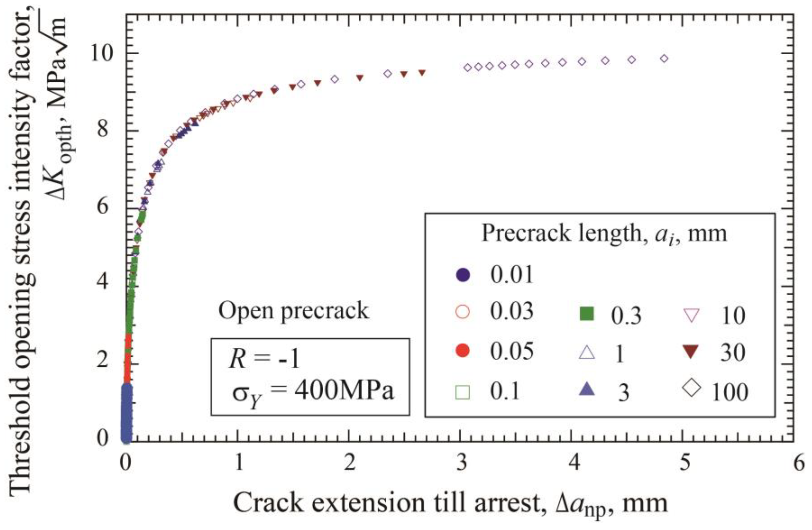
The effect of precrack length on R-curve is examined. Since the increase of ΔKth with crack extension is caused by ΔKopth, the following discussion is focused on the relation between ΔKopth and Δanp. Figure 7 shows the ΔKopth - Δanp relation obtained for ten precrack lengths ranging from 0.01 to 100 mm for open precracks. The ΔKopth value at Δanp = 0 is 0 and increases with crack extension, approaching a constant value. It is worth noting that the difference in the ΔKopth vs. Δanp relation among various precrack lengths is very small. We can draw the conclusion that R-curve is an increasing function of the amount of crack extension and is not influenced by the initial precrack length.
The establishment of the functional form of the cyclic R-curve is important, which can help to determine the shape of the R-curve from a limited amount of data. The following equation was used by McEvily et al. [21] and others [22,23,24,25,26]:
Δ K opth / Δ K opthlc = 1 exp Δ a np / Δ a 1
The following two equations were proposed by Akiniwa and Tanaka [35,36]:
Δ K opth / Δ K opthlc = 1 exp Δ a np / Δ a 2
Δ K opth / Δ K opthlc = Δ a np / Δ a np + Δ a 3
In the above equations, Δa1, Δa2 and Δa3 are fitting parameters and indicate the extent of the short crack region. All three equations show the transition of ΔKopth from 0 to ΔKopthlc as the crack extension Δanp becomes longer. In our previous papers [35,36], it was concluded that Equations (9) and (10) were better fitting formulae than Equation (8) for R-curve. Examples of fitting parameters determined from the simulation data are summarized in Table 1. The values of Δa2 and Δa3 are about the same for the cases of the initial crack length ai = 100 and 1 mm and also equal to those for the other crack lengths. On the other hand, there is a fairly large difference in Δa1.

4.2. Extension of R-Curve for Longer Crack Region

R-curves shown in Figure 7 are determined from constant amplitude loading tests of multiple specimens subjected to different stress amplitudes. R-curve data are also obtainable using step-up amplitude loading of a single specimen, and there is no difference between two R-curves determined by different methods [37]. For each precrack length, the longest crack extension until arrest, Δa*np, is obtained at the fatigue limit, Δσw2. Therefore, in order to extend the R-curve beyond Δa*np, load-shedding or ΔK-constant loading tests should be adapted as reported by Pourheidar et al. [24]. In simulation, a precracked specimen is first subjected to constant amplitude loading until a nonpropagating crack is formed. Then, the applied stress amplitude is increased to a higher stress, followed by the load-shedding procedure until the crack is arrested again. According to ASTM E 647-00 standard [50], the normalized K-gradient, C, in load-shedding tests needs to be
C = 1 K d K d a 0.08 mm 1
when C = 0, ΔK is maintained constant. In simulation, the stress is decreased in each cycle of crack extension, following C = −0.08 mm−1 in load-shedding or C = 0 in ΔK-constant loading tests.
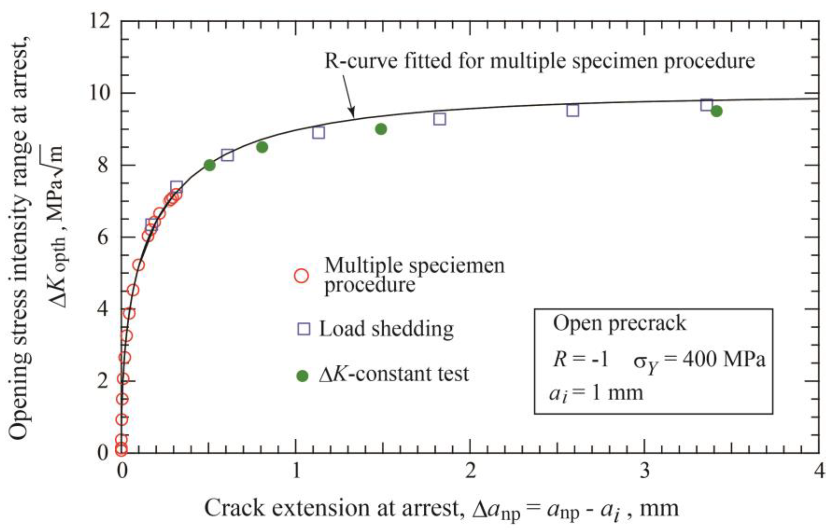
The R-curve for the case of the precrack length of 1 mm is taken as an example next. Under constant amplitude loading, the fatigue limit for crack initiation is Δσw1 = 54 MPa, and the fatigue limit for fracture is Δσw2 = 159 MPa, accompanied by the nonpropagating crack extension of length Δa*np = 0.314 mm. Figure 8 shows an example of load-shedding test. Under Δσ = 140 MPa, the crack extends 0.099 mm and is arrested at ΔK = 8.23 MPa m and ΔKeffth = 3 MPa m . After obtaining the nonpropagating crack of Δa = 0.099 mm, the load-shedding test is started at the stress level of 200 MPa and continued until crack arrest. With crack extension, the applied ΔK is decreased following Equation (11), and ΔKeff also decreases because of buildup of ΔKop as shown in Figure 8. The crack is arrested at the crack extension of Δanp = 0.610 mm in this example. After obtaining the nonpropagating crack extension of 0.099 mm under Δσ = 140 MPa, similar load-shedding tests are started at several different stress levels between 160 and 300 MPa and continued until crack arrest. Using the specimens with nonpropagating crack extension of 0.099 mm under Δσ = 140 MPa, ΔK-constant tests are also carried out at four levels: ΔK = 11, 11.5, 12, and 12.5 MPa m until crack arrest.
Figure 9 shows the relation between ΔKopth and crack extension, Δanp = anpai, obtained by load-shedding and ΔK-constant tests, together with the results of constant amplitude loading of multiple specimens. The line represents the fitted relation of Equation (9) with the parameter given in Table 1. Both data obtained by load-shedding and ΔK-constant loading are plotted at longer nonpropagating cracks and above the limit of the data by constant amplitude loading indicated with the red circles. The data of load-shedding and ΔK-constant tests are fairly close to the fitted line in the whole region. The similar result of nice fitting was observed for the cases of the other precrack lengths. Therefore, it can be concluded that the relation of Equation (9) fitted for the data of constant amplitude loading tests of multiple specimens is applicable for crack extension longer than Δa*np.
For open precracks, fitting parameters Δa2 and Δa3 in Equations (9) and (10) are rather independent of the precrack lengths. Using Δa2 = 0.186 mm, the fitting curves of Equation (9) are drawn in Figure 10 together with the data of constant amplitude loading presented in Figure 4b. As explained in Figure 2 and Figure 3, the final data points for each precrack length correspond to the data at the fatigue limit Δσw2 under constant amplitude loading. Fitting curves are extended beyond the fatigue limit with the solid lines. Published data for the K–T diagram are obtained in various ways, including constant amplitude loading, load-shedding, and ΔK-constant tests using various precrack lengths. It should be noted that the present simulation clearly indicates that the reported data may scatter depending on the test method. Thorough examination of the test methods of published data is necessary together with the preparation method of cracks.
For constant amplitude loading, the connection of the final data points of each precrack length in Figure 10 gives the variation of the maximum value of ΔKth with crack length. The relation between ΔKth and anp for the shortest precrack of 0.01 mm is the upper bound of the ΔKth vs. anp relation. In the case of the crack initiation stage included in R-curve, the upper bound relation is obtained for the case of the initiation crack length a1 = 0.022 mm as described in the next section (refer Equation (14)).

4.3. Inclusion of Crack Initiation Stage in R-Curve

It is well known that the K–T diagram of threshold stress range vs. precrack length can be divided into three regions [28,45,46,47,51]. In Region 1 of very short precracks whose length is less than a1, the precracks are nondamaging, without reducing the fatigue limit. For Region 3 above a2, the constant ΔKth value is applicable for the crack growth threshold. In between Region 1 and 3, Region 2 is the micro crack region. In the preceding sections, we deal with short crack behavior in Region 2 based on the buildup of crack closure. For precracks longer than a1, there is no crack initiation stage; therefore, ΔKopth-curve expressions of Equations (9) and (10) are directly applicable. When applied to precracks less than a1, the present analysis should be modified. In those cases, fatigue fracture is caused by naturally formed cracks but not by existing precracks. The fatigue limit of smooth specimens is controlled not by crack initiation but by crack propagation [4,5,6,7,8]. The fatigue limit for crack initiation is less than the fatigue limit for fracture, Δσw0, and is here denoted by Δσw01.
The fatigue limit of steels with the yield strength of 400 MPa can be estimated as follows. The yield stress of steels, σY, is closely related to the ferrite grain size d. Etou et al. [52] proposed the following Hall-Pech relation between σY [MPa] and d [m] for ferritic steels for the range of yield stress from 100 to 700 MPa:
σ Y = 100 + 0.600 / d
From this equation, the grain size of the present steel with σY = 400 MPa is estimated to be 4 μm. Next, the fatigue limit of smooth specimens may be obtainable from the following Hall-Petch relation between the fatigue limit Δσw0 [MPa] and the grain size d [m] reported by Tachibana et al. [7] for steel WELL-TEN 60:
Δ σ w 0 = 373 + 0.267 / d
The estimated fatigue limit is 506 MPa.
In order to apply the R-curve method to smooth specimens, the crack initiation stage should be taken into account. In our previous study of notch fatigue [16], the crack initiation stage took place first, and then the crack propagation stage followed. In these cases, we assumed that the crack nucleated at the notch root was closure-free, and crack closure was built up as a function of the amount of extension from the nucleated crack. When nucleated cracks are open cracks, the R-curve with the fitting function of Equation (9) is modified to
Δ K th = Δ K effth + Δ K thlc Δ K effth 1 exp a a 1 / Δ a 2
where a1 is the initiation crack length and Δa2 = 0.186 mm.
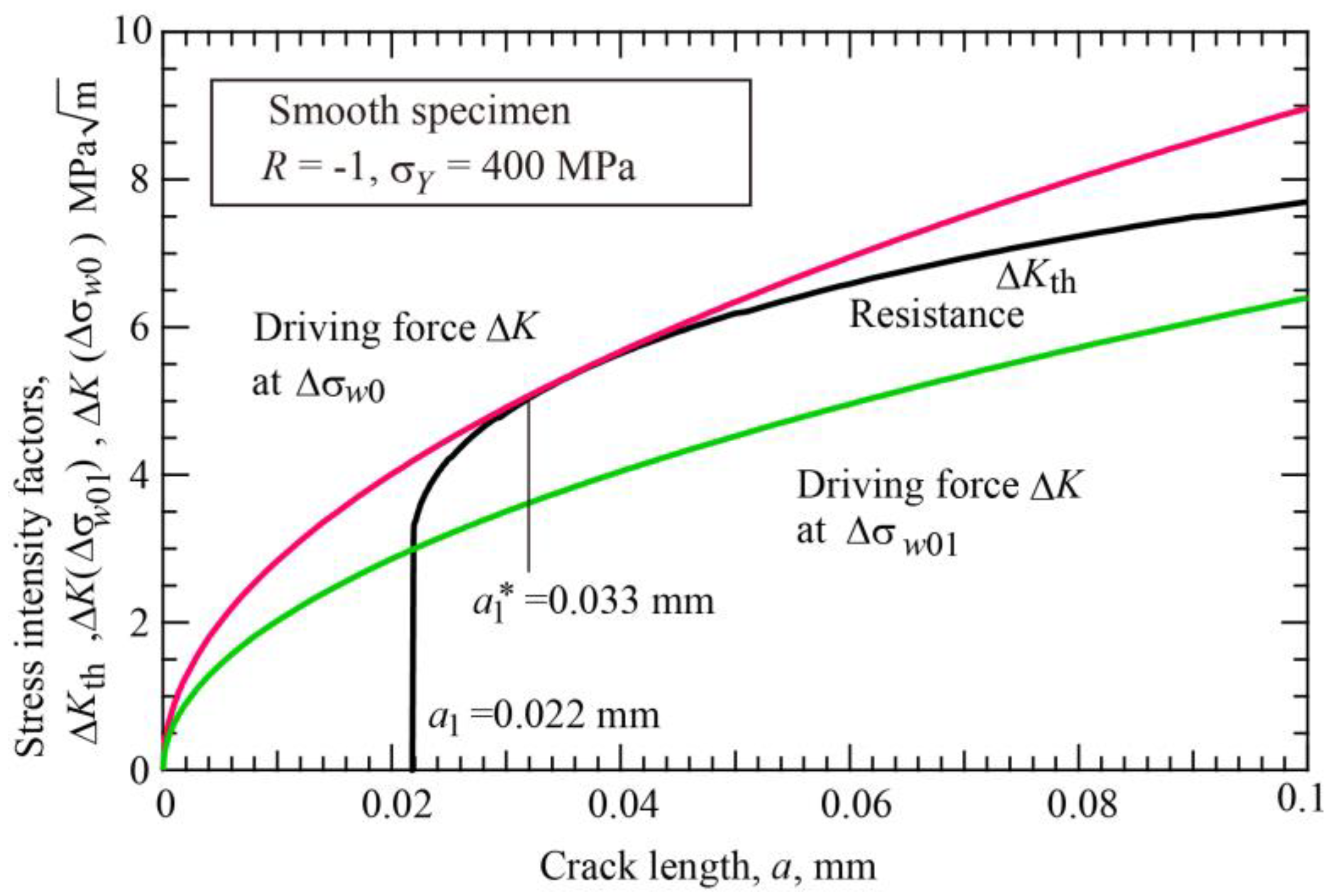
Using Equation (14) and the fatigue limit Δσw0 = 506 MPa, the initiation crack length a1 can be determined as follows. The necessary data for Equation (14) are given in Table 1. Figure 11 shows the R-curve method applied to smooth specimens to determine the a1 length. The red line is the driving force corresponding to Δσw0, and the black line is the R-curve, Equation (14). From the condition that the driving force is the tangent of the R-curve, the a1 length is determined as 0.022 mm. In this diagram, the green line crossing the point of the a1 and ΔKeffth corresponds to the crack initiation limit of smooth specimens, Δσw01, and is given by
Δ σ w 01 = Δ K effth / π a 1
The calculated value is Δσw01 = 361 MPa. The nonpropagating crack at Δσw0 has the length at the contact point of the driving force and R-curve in Figure 11, i.e., a1* = 0.033 mm. The amount of crack extension from the initial length to the final length is 0.011 mm. The initiation crack length a1 determined is 5.5 times the grain size. Zerbst and Madia [23] determined the initiation crack size in a similar way for S355NL steel with the yield stress of 373 MPa. Their initial crack length is a1 = 0.035 mm, and the nonpropagating crack length is a1* = 0.05 mm, which are roughly the same order.
The same results can be obtained from the K–T diagram of the threshold stress range against the initial crack length (Type A plot) as shown in Figure 12. The horizontal line of Δσw0 = 506 MPa crosses the line of Δσw2 vs. ai relation at the crack length 0.022 mm, which is the initiation crack length a1. The vertical line at crack length a1 crosses the crack initiation line of Δσw1 vs. ai relation at 361 MPa, which corresponds to the fatigue limit for crack initiation Δσw01 of smooth specimens.
The ratio of Δσw01 to the fatigue limit Δσw0 is 0.72. Many researchers reported that the crack initiation limit was less than the fatigue limit for fracture of smooth specimens of steels [4,6,8]. Nakazawa et al. [4] reported that the ratio of Δσw01 to the fatigue limit Δσw0 was around 0.76 to 0.79, while Yamada et al. [6] reported that the ratio was about 0.9, and Tanaka et al. [8] reported 0.79. The simulated ratio of 0.72 is slightly below the experimental data, and the low ratio may result from the neglection of crack closure of naturally initiated a1-sized cracks as described below.
Based on the microscopic observations near the fatigue threshold of smooth specimens of steels, Stage I shear cracks are normally formed along slip bands within a favorably oriented grain situated on the surface. After crossing the grain boundary, the crack gradually turns the growth direction along the plane perpendicular to the stress axis, often leaving a zigzag-shaped crack path. Nakazawa et al. [4] and Yamada et al. [5,6,7] reported that the fatigue limit of steel smooth specimens is controlled by the onset of Stage II propagation from shear mode or zigzag-shaped Stage I cracks. The maximum size of nonpropagating cracks observed below the fatigue limit of ferritic steels, Δσw0, ranges from a few grain sizes to an order of magnitude larger than the grain size depending on the microstructure [4,5,6,7,8]. Yamada et al. [5,6,7] suggested that large nonpropagating cracks below the fatigue limit were formed by connecting small shear cracks made in individual grains. The propagation of microstructurally small cracks can be blocked by the microstructural barriers, such as grain boundaries and phase boundaries, as proposed by Miller [14]. Akiniwa et al. showed both microstructural barrier and crack closure could cause the nonpropagation of small cracks below the fatigue limit of smooth specimens [15]. The present simulation is based on continuum mechanical analysis of crack closure development and does not take the microstructure into account. We interpreted the initiation crack length a1 in R-curves as the length at the transition from the microstructurally to the mechanically/physically short cracks as explained by Zerbst and Madia [23]. The initiation crack size is longer than the microstructural size or grain size, where the crack begins to show isotropic mechanical properties. At the same time, crack closure begins to develop. We conclude that the fatigue limit of smooth specimens is determined by the continuation of Stage II crack (or mechanically/physically small cracks) propagation, and the condition of growth or arrest of cracks is judged by using the R-curve method.
The above discussion is focused on Type I open precracks, but naturally initiated cracks may not be fully open. Stage I shear cracks may have a zigzag shape and have RICC. The initiated crack of length a1 may not be closure-free. In this case, the crack initiation condition shown in Equation (15) should be modified to include the contribution of crack closure using the effective fraction U, as follows:
Δ σ w 01 = Δ K effth U π a 1
Since U is less than 1, the ratio of Δσw01/Δσw0 becomes larger than 0.72, approaching experimental values. Subsequent development of crack closure is also influenced by the type of nucleated cracks. Further research is required for precise comparison between simulation results and experimental data.
Chapetti [27,28] proposed a method different from the R-curve method described above. He derived R-curve on the basis of the relations between ΔKth and crack length a in the K–T diagram reported by several investigators. He assumed that the ΔKth was a single-valued function of the current crack length, a, and independent of precrack length. He proposed the following formula:
Δ K th = Δ K dR + Δ K thlc Δ K dR 1 exp k a d
where d is the grain size, ΔKdR is the microstructural threshold, k is a fitting parameter. The fatigue limit of smooth specimens, Δσw0, is related to ΔKdR as follows:
Δ K dR = Y Δ σ w 0 π d
where Y is the geometrical correction factor and is 0.65 for a semi-circular crack. For k, they proposed the following estimate:
k = 1 4 d Δ K dR Δ K thlc Δ K dR
Table 2 summarizes the data required for calculation of Equation (17), where Δa1 = 1/k.
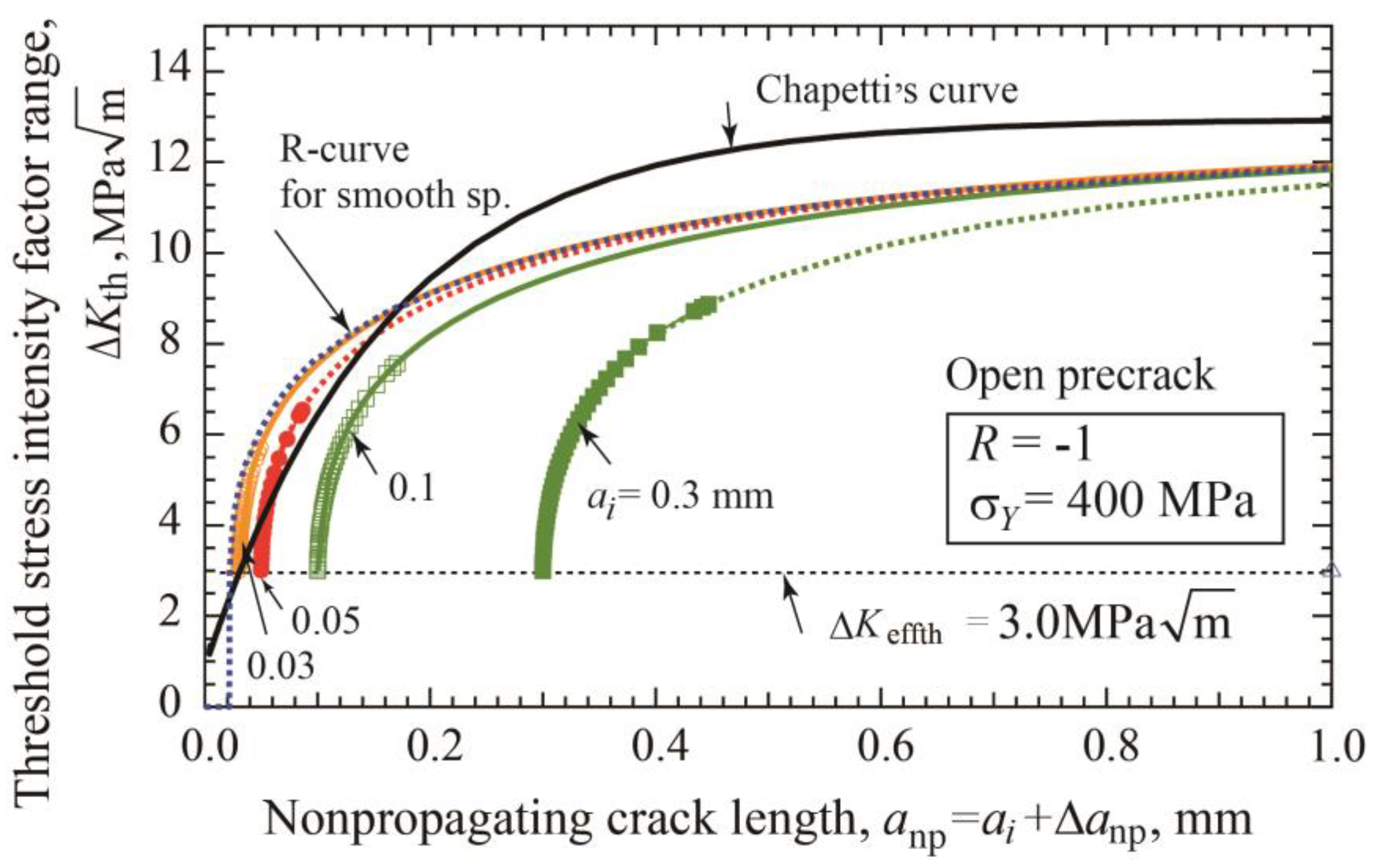
Figure 13 shows the change of ΔKth with crack length a plotted in linear scale diagram. R-curves for smooth specimens of Equation (14) and Chapetti’s curve of Equation (17) are drawn together with R-curves of specimens with precrack lengths of 0.03, 0.05, 0.1, and 0.5 mm. The R-curve of smooth specimens gives the upper bound of the other R-curves obtained for various lengths by simulation. Chapetti’s curve seems to be rather close to the R-curve for smooth specimens, but there is still a fairly large difference. It should be noted that there is one significant difference between the present R-curve method and Chapetti’s method. Chapetti claimed that the relation, Equation (17), was always applicable to predict the threshold ΔKth value using the total crack length a, independent of the initial precrack length. When the crack starts in smooth specimens, there is not much difference between Chapetti’s equation, Equation (17), and our equation, Equation (14). On the other hand, when the crack started from crack-like defects or closure-free precracks, the ΔKth is a single-valued function of amount of crack extension and not of the total crack length, as shown in Figure 10 and Figure 13 according to the present R-curve method. Further experimental examination would be necessary to resolve this contradiction.

5. Concluding Remarks

The buildup of PICC with crack extension from crack-like defects or precracks is simulated using a modified strip yield model under completely reversed loading. Closure-free precracks are assumed, having an initial clearance to remain open even under compression. The main results are summarized as follows:
(1)
At crack initiation, the crack-tip opening stress is equal to the applied minimum stress and increases sharply with crack extension. The effective range of stress intensity factor ΔKeff first drops and then changes to increase. Under the assumption of the threshold value of ΔKeff for steels as ΔKeffth = 3 MPa m , the crack is arrested when ΔKeff drops below ΔKeffth.
(2)
There are two fatigue limits: Δσw1 is for crack initiation and Δσw2 is for fracture. As the precrack length becomes longer, the amount of extension of the onpropagating crack at Δσw2 becomes larger and the threshold SIF range, ΔKth, approaches a steady state value for long cracks ΔKthlc.
(3)
The threshold SIF range ΔKth consists of two components: ΔKeffth and ΔKopth, where ΔKeffth is constant and ΔKopth is an increasing function of crack extension Δanp. The relation between ΔKth and Δanp, called cyclic R-curve, is independent of the initial precrack length. Two fitting functions proposed for R-curves will be useful to determine R-curves from limited experimental data.
(4)
Load-shedding or ΔK-constant loading tests can be adapted to extend the cyclic R-curve beyond the fatigue limit of a precracked specimen under constant amplitude loading. For a given precrack length, the relation between ΔKth and the crack extension Δa is unique, following the fitted functions.
(5)
For precracks shorter than the initiation crack length a1, the crack initiation stage of forming a crack length of a1 should be taken into account in R-curves. The length of the initiation crack, a1, is determined from the fatigue limit of smooth specimens, Δσw0, and the R-curve having the crack initiation stage.
(6)
The propagation of the initiation crack of length a1 controls the fatigue limit of smooth specimens. The initiation crack length may correspond to the length at the transition from microstructurally short cracks to mechanically/physically short cracks and is several times larger than the grain size.

Author Contributions

Conceptualization, writing—original draft preparation, methodology, investigation, formal analysis, K.T.; writing—review and editing, software, methodology, formal analysis, Y.A. All authors have read and agreed to the published version of the manuscript.

Funding

This research received no external funding.

Institutional Review Board Statement

Not applicable.

Informed Consent Statement

Not applicable.

Data Availability Statement

The original contributions presented in the study are included in the article; further inquiries can be directed to the corresponding authors.

Conflicts of Interest

The authors declare no conflicts of interest.

Appendix A. Simulation of PICC Buildup Using a Modified Strip-Yield Model

In the simulation, we assume the plane stress state and the material is perfectly plastic without work hardening. In strip yielding at the maximum stress, the crack wake and the plastic zone are divided by a finite number of elements. The plastic zone ahead of the crack tip is divided into 40 elements, where the division is denser near the precrack tip. A precrack is also divided into 20 elements with uneven width, where the division is denser near the precrack tip. The details of the computational procedure are presented in our preceding papers [34,35]. They are listed as follows:
(i)
Lumping of elements in the crack wake is carried out in order to suppress the increase of the number of elements due to crack extension.
(ii)
Under the maximum stress, σmax, the crack opening displacement (COD) is determined as the sum of CODs due to the applied stress and to the yield stress, σY, in the plastic zone.
(iii)
During unloading to the minimum stress, σmin, the stress in the plastic zone is reversed to yield in compression, and the crack faces start to contact. As described above, the initial clearance is assumed for open (Type I) precrack surfaces. The stresses in the plastic zone and on the contacted crack wake are determined by solving the simultaneous linear equations for element stresses with the Gauss-Seidel method. The element stress, σi, is modified as follows: (a) For the whole region, if σi < −σY, then σi = −σY. (b) For elements in the crack wake, if σi > 0, then σi = 0. (c) For elements in the plastic zone, if σi > σY, then σi = σY, because the material is assumed to be perfectly plastic.
(iv)
The crack-tip opening stress, σop, is determined from the contact stress on the crack face.
(v)
At the minimum stress, the crack is extended by da, and one element of size da is added behind the crack tip. The amount of crack extension in one cycle of simulation is determined as 0.2% of the maximum plastic zone size.
(vi)
After crack extension, the above process of computation is repeated until the crack reaches a prescribed length or is arrested because of increasing crack closure.

References

  1. Frost, N.E.; Marsh, K.J.; Pook, L.P. Matal Fatigue; Clarendon Press: Oxford, UK, 1974; pp. 130–201. [Google Scholar]
  2. Isibasi, T. Prevention of Fracture and Fatigue; Yokendo: Tokyo, Japan, 1967; pp. 52–86. [Google Scholar]
  3. Nisitani, H. Effects of size on the fatigue limit and the branch point in rotary bending tests of carbon steel specimens. Bull. JSME 1968, 11, 947–957. [Google Scholar] [CrossRef]
  4. Nakazawa, H.; Kobayashi, H.; Morita, A.; Itakura, S.; Miyauchi, K.; Ishii, Y. Fatigue crack growth and fatigue limit of smooth and notched specimens of low-carbon steel with various grain sizes. Trans. Jpn. Soc. Mech. Eng. 1974, 40, 9–19. [Google Scholar] [CrossRef]
  5. Tamura, M.; Yamada, K.; Shimizu, M.; Kunio, T. Endurance limit and nonpropagating crack behavior of ferritic pearlitic steels. Trans. Jpn. Soc. Mech. Eng. 1983, 49, 1378–1386. [Google Scholar] [CrossRef]
  6. Yamada, I.; Yamada, K.; Kunio, T. Effect of grain size on threshold behaviour of small crack in plain carbon steel. Trans. Jpn. Soc. Mech. Eng. 1986, 52, 412–416. [Google Scholar] [CrossRef]
  7. Tachibana, S.; Kawachi, S.; Yamada, K.; Kunio, T. Effect of grain refinement on the endurance limit of plane carbon steels at various strength levels. Trans. Jpn. Soc. Mech. Eng. 1988, 54, 1956–1961. [Google Scholar] [CrossRef]
  8. Tanaka, K.; Akiniwa, Y.; Nakano, M.; Kinefuchi, M. Propagation threshold and crack closure of small fatigue cracks. Trans. Jpn. Soc. Mech. Eng. 1990, 56, 715–722. [Google Scholar] [CrossRef]
  9. Smith, R.A.; Miller, K.J. Prediction of fatigue regimes in notched components. Int. J. Mech. Sci. 1978, 20, 201–206. [Google Scholar] [CrossRef]
  10. El Haddad, M.H.; Dowling, N.E.; Topper, T.H.; Smith, K.N. J integral applications for short fatigue cracks at notches. Int. J. Fract. 1980, 16, 15–30. [Google Scholar] [CrossRef]
  11. Tanaka, K.; Nakai, Y. Propagation and nonpropagation of short fatigue cracks at a sharp notch. Fatigue Fract. Eng. Mater. Struct. 1983, 6, 315–327. [Google Scholar] [CrossRef]
  12. Nishikawa, I.; Konishi, M.; Miyoshi, Y.; Ogura, K. Small fatigue crack growth at notch root in elastic-plastic range. J. Soc. Mater. Sci. Jpn. 1986, 35, 904–910. [Google Scholar] [CrossRef]
  13. Abdel-Raouf, H.; Topper, T.H.; Plumtree, A. A model for the fatigue limit and short crack behaviour related to surface strain distribution. Fatigue Fract. Eng. Mater. Struct. 1992, 15, 895–909. [Google Scholar] [CrossRef]
  14. Miller, K.J. Materials science perspective of metal fatigue resistance. Mater. Sci. Technol. 1993, 9, 453–462. [Google Scholar] [CrossRef]
  15. Akiniwa, Y.; Tanaka, K.; Kimura, H. Microstructural effects on crack closure and propagation threholds of small fatigue cracks. Fatigue Fract. Eng. Mater. Struct. 2001, 24, 817–829. [Google Scholar] [CrossRef]
  16. Tanaka, K.; Akiniwa, Y. Resistance-curve method for predicting propagation threshold of short cracks at notches. Eng. Fract. Mech. 1988, 30, 863–876. [Google Scholar] [CrossRef]
  17. Zhang, L.M.; Akiniwa, Y.; Tanaka, K. Fatigue strength evaluation of cracked components. JSME Int. J. Ser. A Solid Mech. Mater. Eng. 1997, 40, 445–452. [Google Scholar] [CrossRef]
  18. Akiniwa, Y.; Zhang, L.M.; Tanaka, K. Prediction of the fatigue limit of cracked specimens based on the cyclic R-curve method. Fatigue Fract. Eng. Mater. Struct. 1997, 20, 1387–1398. [Google Scholar] [CrossRef]
  19. Pippan, R. Threshold and effective threshold offatigue crack propagation in ARMCO iron I: The influence of grain size and cold working. Mater. Sci. Eng. A 1991, 138, 1–13. [Google Scholar] [CrossRef]
  20. Pippan, R.; Plöchl, L.; Klanner, J.; Stüwe, H.P. The use of fatigue specimens pre-cracked in compression for measuring threshold values and crack growth. J. Test. Eval. 1994, 22, 98–103. [Google Scholar] [CrossRef]
  21. McEvily, A.J.; Endo, M.; Murakami, Y. On the relationship and the short fatigue crack threshold. Fatigue Fract. Eng. Mater. Struct. 2003, 26, 269–278. [Google Scholar] [CrossRef]
  22. Kolitsch, S.; Gänser, H.P.; Maierhofer, J.; Pippan, R. Fatigue crack growth threshold as a design criterion- statistical scatter and load ratio in the Kitagawa-Takahashi diagram. IOP Conf. Ser. Mater. Sci. Eng. 2016, 119, 012015. [Google Scholar] [CrossRef]
  23. Zerbst, U.; Madia, M. Fracture mechanics base assessment of the fatigue strength: Approach for the determination of the initial crack size. Fatigue Fract. Eng. Mater. Struct. 2015, 38, 1066–1075. [Google Scholar] [CrossRef]
  24. Pourheidar, A.; Patriarca, L.; Madia, M.; Werner, S.; Beretta, S. Progress in the determination of the cyclic R-curve and its application to fatigue assessment. Eng. Fract. Mech. 2022, 260, 108122. [Google Scholar] [CrossRef]
  25. Zerbst, U.; Madia, M.; Vormwald, M.; Beier, H.T. Fatigue strength and fracture mechanics—A general perspective. Eng. Fract. Mech. 2018, 198, 2–23. [Google Scholar] [CrossRef]
  26. Maierhofer, J.; Kolitsch, S.; Pippan, R.; Gänser, H.-P.; Madia, M.; Zerbst, U. The cyclic R-curve—Determination, problems, limitations and application. Eng. Fract. Mech. 2018, 198, 45–64. [Google Scholar] [CrossRef]
  27. Chapetti, M.D. Fatigue propagation threshold of short cracks under constant amplitude loading. Int. J. Fatigue 2003, 25, 1319–1326. [Google Scholar] [CrossRef]
  28. Chapetti, M.D. Fracture mechanics for fatigue design of metallic components and small defect assessment. Int. J. Fatigue 2022, 154, 106550. [Google Scholar] [CrossRef]
  29. Tanaka, K. Fatigue crack propagation. In Comprehensive Structural Integrity; Ritchie, R.O., Murakami, Y., Eds.; Elsevier: London, UK, 2003; Volume 4: Cyclic Loading and Fatigue, pp. 95–127. [Google Scholar]
  30. Budiansky, B.; Hutchinson, J.W. Analysis of closure in fatigue crack growth. J. Appl. Mech. 1978, 45, 267–276. [Google Scholar] [CrossRef]
  31. Dugdale, D.S. Yielding of steel sheet sheets containing cracks. J. Mech. Phys. Solids 1960, 8, 100–104. [Google Scholar] [CrossRef]
  32. Newman, J.C., Jr. A crack-closure model for predicting crack growth under aircraft spectrum loading. In Methods and Models for Predicting Fatigue Crack Growth under Random Loading; Chang, J.B., Hudson, H.D., Eds.; ASTM: West Conshohocken, PA, USA, 1981; pp. 533–584. [Google Scholar] [CrossRef]
  33. Toyosada, M.; Gotoh, K.; Niwa, T. Fatigue crack propagation for a through thickness crack: A crack propagation law considering cyclic plasticity near the crack tip. Int. J. Fatigue 2004, 26, 983–992. [Google Scholar] [CrossRef]
  34. Ferreira, S.E.; Castro, J.T.P.; Meggiolaro, M.A. Using the strip-yield mechanics to model fatigue crack growth by damage accumulation ahead of the crack tip. Int. J. Fatigue 2017, 103, 557–575. [Google Scholar] [CrossRef]
  35. Tanaka, K.; Akiniwa, Y. Fatigue thresholds of precracked specimens predicted by modified strip-yield model for plasticity-induced crack closure. Theor. Appl. Fract. Mech. 2022, 122, 103635. [Google Scholar] [CrossRef]
  36. Tanaka, K.; Akiniwa, Y. The cyclic R-curve method for predicting fatigue growth threshold based on nidified strip-yield model of plasticity-induced crack closure under fully reversed loading. Eng. Fract. Mech. 2023, 284, 109194. [Google Scholar] [CrossRef]
  37. Tanaka, K.; Akiniwa, Y. Determination of cyclic R-curve for predicting short fatigue crack growth. Theor. Appl. Fract. Mech. 2024, 133, 104544. [Google Scholar] [CrossRef]
  38. Minakawa, K.; McEvily, A.J. On near-threshold fatigue crack growth in steels and aluminum alloys. In Fatigue Thresholds; Bacland, J., Blom, A.F., Beevers, C.J., Eds.; Engineering Materials Advisory Service: Warly, UK, 1982; pp. 373–390. [Google Scholar]
  39. Akiniwa, Y.; Tanaka, K. Prediction of fatigue limits of engineering components containing small defects. In Fatigue Crack Growth Thresholds, Endurance Limits, and Design; Newman, J.C., Jr., Piascik, J.C., Eds.; ASTM: West Conshohocken, PA, USA, 2000; pp. 304–318. [Google Scholar] [CrossRef]
  40. Kikukawa, M. Measurement of fatigue crack propagation and crack closure at low stress intensity level by unloading compliance method. J. Soc. Mater. Sci. Jpn. 1976, 25, 899–903. [Google Scholar] [CrossRef]
  41. Liaw, P.K.; Leak, T.R.; Logsdon, W.A. Near-threshold fatigue crack growth behavior in metals. Acta Metall. 1983, 31, 1581–1587. [Google Scholar] [CrossRef]
  42. Duarte, L.; Schönherr, J.A.; Madia, M.; Zerbst, U.; Geilen, M.B.; Klein, M.; Oechsner, M. Recent developments in the determination of fatigue crack propagation thresholds. Int. J. Fatigue 2022, 164, 107131. [Google Scholar] [CrossRef]
  43. .Riemelmoser, F.O.; Gumbsch, P.; Pippan, R. Dislocation modelling of fatigue cracks: An overview. Mater. Trans. 2001, 42, 2–13. [Google Scholar] [CrossRef]
  44. Pokluda, J.; Pippan, R.; Vojtek, T.; Hohenwarter, T.A. Near-threshold behaviour of shear-mode fatigue cracks in metallic materials. Fatigue Fract. Eng. Mater. Struct. 1989, 37, 232–254. [Google Scholar] [CrossRef]
  45. Kitagawa, H.; Takahashi, S. Applicability of fracture mechanics to very small crack or cracks in early stage. In Proceedings of the 2nd International Conference on Mechanical Behavior of Materials, Boston, MA, USA, 16–20 August 1976; pp. 627–631. [Google Scholar]
  46. El Haddad, M.H.; Smith, K.N.; Topper, T.H. Fatigue crack propagation of short cracks. J. Eng. Mater. Technol. 1979, 101, 42–46. [Google Scholar] [CrossRef]
  47. Tanaka, K.; Nakai, Y.; Yamashita, M. Fatigue growth threshold of small cracks. Int. J. Fract. 1981, 17, 519–533. [Google Scholar] [CrossRef]
  48. Murakami, Y.; Endo, M. Quantitative evaluation of fatigue strength of metals containing various small defects or cracks. Eng. Fract. Mech. 1983, 17, 1–15. [Google Scholar] [CrossRef]
  49. Murakami, Y.; Endo, M. Effect of hardness and crack geometries on ΔKth of small cracks emanating from small defects. In The Behaviour of Short Fatigue Cracks; Miller, K.J., de Los, E.R., Eds.; Mechanical Engineering Publications: London, UK, 1986; pp. 275–293. [Google Scholar]
  50. ASTM E 647-23a; Standard Test Method for Measurement of Fatigue Crack Growth Rates. ASTM International: West Conshohocken, PA, USA, 2024.
  51. Schönbauer, B.M.; Mayer, H. Effect of small defects on the fatigue strength of martensitic stainless steels. Int. J. Fatigue 2019, 127, 362–375. [Google Scholar] [CrossRef]
  52. Etou, M.; Fukushima, S.; Sasaki, T.; Hiraguchi, Y.; Miyata, K.; Wakita, M.; Tomida, T.; Imai, N.; Yoshida, M.; Okada, Y. Super short multi-pass rolling process for ultrafine-grained hot strip. ISIJ Int. 2008, 48, 1142–1147. [Google Scholar] [CrossRef]
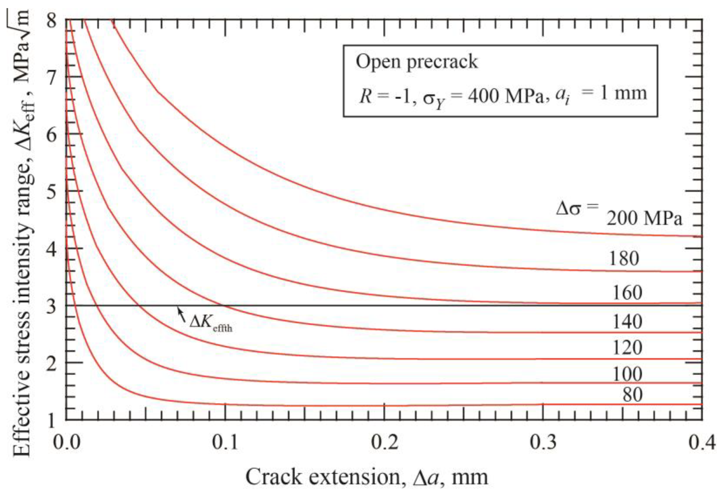
Figure 1. Change of ΔKeff with crack extension under several applied stresses for precrack of 1 mm length (σY = 400 MPa, R = −1, open precrack).
Materials 17 04484 g001
Figure 2. Change of crack extension until arrest with the applied stress range for precracks with various lengths (σY = 400 MPa, R = −1, open precrack).
Materials 17 04484 g002
Figure 3. Crack extension until arrest, Δanp, at Δσw2 as a function of precrack length (σY = 400 MPa, R = −1, open precrack).
Materials 17 04484 g003
Figure 4. Change of nonpropagating crack length with stress range and SIF range for various precrack lengths from 0.01 to 100 mm (σY = 400 MPa, R = −1, open precrack). (a) Stress range/double yield stress vs. nonpropagating crack length. (b) Threshold SIF range vs. nonpropagating crack length.
Materials 17 04484 g004
Figure 5. Changes in threshold stresses for crack initiation and fracture with crack length (σY = 400 MPa, R = −1, open precrack).
Materials 17 04484 g005
Figure 6. Changes in threshold SIF ranges for crack initiation and fracture with crack length (σY = 400 MPa, R = −1, open precrack).
Materials 17 04484 g006
Figure 7. Effect of precrack length on the change of ΔKopth with crack extension Δanp at the threshold (σY = 400 MPa, R = −1, open precrack).
Materials 17 04484 g007
Figure 8. Changes in stress intensity factors ΔK, ΔKop, and ΔKeff, in load-shedding test for open precrack with length of 1 mm (σY = 400 MPa, R = −1).
Materials 17 04484 g008
Figure 9. R-curve determined by constant-amplitude loading, load-shedding, and ΔK-constant loading tests for open precrack with ai = 1 mm (σY = 400 MPa, R = −1).
Materials 17 04484 g009
Figure 10. Changes in threshold stress intensity factor with nonpropagating crack length for open precracks. R-curves are fitted by Equation (9) (σY = 400 MPa, R = −1).
Materials 17 04484 g010
Figure 11. R-curve method for determination of thresholds of smooth specimens (σY = 400 MPa, R = −1).
Materials 17 04484 g011
Figure 12. Diagram of fatigue limits for crack initiation and fracture against precrack size in order to determine the crack initiation length of smooth specimens (σY = 400 MPa, R = −1, Type A plot).
Materials 17 04484 g012
Figure 13. Relation between the threshold stress intensity and the nonpropagating crack length for smooth and precracked specimens (σY = 400 MPa, R = −1, open precrack).
Materials 17 04484 g013
Table 1. Fitting parameters for R-curves for open precracks with the initial lengths of 1 and 100 mm (σY = 400 MPa, R = −1).
Precrack Length
ai [mm]
Threshold ΔKop
for Long Crack
ΔKopthlc [ MPa m ]
Threshold ΔKeff
ΔKeffth
[ MPa m ]
Threshold ΔKth
for Long Crack
ΔKthlc [ MPa m ]
Parameter
in Equation (8)
Δa1 [mm]
Parameter
in Equation (9)
Δa2 [mm]
Parameter
in Equation (10)
Δa3 [mm]
1009.943.0012.940.1570.1860.253
19.943.0012.940.1720.1840.266
Table 2. Material properties for R-curve of steels with crack-like defects (σY = 400 MPa, R = −1).
Grain Size
d [mm]
Fatigue Limit
Smooth Spec. (Fracture)
Δσw0 [MPa]
Fatigue Limit Smooth Spec.
(Crack Init.)
Δσw01 [MPa]
Crack
Initiation Length
a1 [mm]
Fitting
Parameter
in Equation (14)
Δa2 [mm]
Mi-cro-Threshold
ΔKdR
m P a m
Fitting
Parameter
in Equation (17)
k [1/mm]
Fitting
Parameter
Δa1 = 1/k
[mm]
0.0045063610.0220.1861.176.190.162
Disclaimer/Publisher’s Note: The statements, opinions and data contained in all publications are solely those of the individual author(s) and contributor(s) and not of MDPI and/or the editor(s). MDPI and/or the editor(s) disclaim responsibility for any injury to people or property resulting from any ideas, methods, instructions or products referred to in the content.