Review

Aluminum Conductor Steel-Supported Conductors for the Sustainable Growth of Power Line Capacity: A Review and Discussion

1
Department of Physics, Faculty of Science, Lorestan University, Khorramabad P.O. Box 465, Iran
2
Pooya Power Knowledge Enterprise, Tehran 1466993771, Iran
3
Department of Electrical Engineering, Universitat Politècnica de Catalunya, 08222 Terrassa, Spain
4
Department of Mechanical Engineering, University of Birmingham, Edgbaston, Birmingham B15 2TT, UK
*
Author to whom correspondence should be addressed.
Materials 2024, 17(18), 4536; https://doi.org/10.3390/ma17184536
Submission received: 8 August 2024 / Revised: 7 September 2024 / Accepted: 13 September 2024 / Published: 15 September 2024
(This article belongs to the Section Energy Materials)

Abstract

:
Industrial development and population growth have increased the need for higher-capacity power transmission lines. Aluminum conductor steel-supported (ACSS) conductors, a type of high-temperature low-sag (HTLS) conductor, are now widely used in new designs and reconductoring applications. ACSS conductors are preferred over traditional aluminum conductor steel-reinforced (ACSR) conductors due to their high strength, low sag, and excellent thermal stability. These attributes have garnered significant interest from researchers, engineers, and manufacturers. This paper provides a comprehensive review of the structure, properties, testing methods, and environmental behavior of ACSS conductors.

1. Introduction

Electricity is crucial for the well-being of citizens and the social prosperity of developed economies. Over the last two decades, the scientific community has shown a growing research interest in various perspectives related to electricity WW [1]. The occurrence of energy losses along power delivery network has persistently captured the attention of researchers. There are various ways to improve transmission line efficiency and reduce losses including uprating [2,3,4,5], reconductoring [6], dynamic line rating [7,8,9,10,11], energy storage integration [12,13], dynamic thermal rating, network topology optimization [14,15], and real-time online analysis [16,17]. Overhead conductors are cost-effective and reliable for transmitting high amounts of electrical power over long distances. They are easy to repair, flexible, and have a longer lifespan compared to underground cables. This makes them a versatile and important component of the power industry. ACSR conductors are the most widely used type of conductor in power transmission lines. They have a central steel core surrounded by several layers of aluminum strands. The steel core provides the conductor with strength and support, while the aluminum strands provide good electrical conductivity. ACSR conductors sag excessively at high temperatures, which limits their ability to meet the growing demand for electricity and transmission capacity. The increasing popularity of HTLS conductors for high-voltage lines presents a favorable choice for replacing ACSR conductors and enhancing the responsiveness of the power supply network [2,18,19,20,21,22,23]. While conventional conductors typically operate at temperatures below 75 °C, ACSS conductors have the capability to operate continuously at temperatures of at least 150 °C [3,24]. The most important types of high-capacity conductors (HTLS) based on their brand are ACSS, super-thermal-resistant aluminum conductor invar-reinforced (ZTACIR), gap type aluminum conductor steel-reinforced (GTACSR), aluminum conductor composite-reinforced (ACCR), and aluminum conductor composite core (ACCC) [3,4,5,6,25,26,27]. ACSS conductors are the right choice to meet the growing needs of modern power transmission systems where higher current-carrying capacity is needed [28]. ACSS conductors were first introduced in 1970. At that time, the name of this conductor was steel-supported aluminum conductor (SSAC) [29,30]. ACSS conductors have garnered significant attention due to their unique design and benefits over conventional conductors. Made of high-strength aluminum alloy strands wrapped around a central steel core, ACSS conductors improve current-carrying capacity, reduce thermal expansion effects, and enhance overall system reliability [3,31,32]. This review highlights the construction, material properties, production processes, and key considerations related to ACSS conductors. Moreover, the study delves into critical factors such as creep behavior, stress–strain characteristics, short-circuit current handling capability, electrical resistance, self-damping, current–temperature relationships, corona discharge, sag–temperature behavior, lightning, galloping, aeolian vibrations, fretting fatigue, environmental impacts, and sustainable development.

2. Construction and Materials

ACSS conductors consist of fully annealed aluminum or aluminum-alloy wires stranded around a steel core, which may be galvanized, aluminum-clad, or Galfan-coated. The wires have either a circular or trapezoidal cross-section [33,34,35,36,37]. High electrical conductivity in aluminum wires is crucial, necessitating the use of electrical conductor (EC)-grade aluminum with a minimum purity of 99.5% [38]. Balancing mechanical strength, electrical conductivity, and high-temperature operation in aluminum conductors is challenging due to the inverse relationship between strength and conductivity [39]. Aluminum alloys with suitable properties can address this issue. Studies have explored the use of alloying elements like zirconium, scandium, yttrium, and erbium to achieve an optimal combination of strength, conductivity, and thermal stability [33,39,40,41,42,43,44,45,46]. Elements like Zr and Sc control grain sizes in recrystallization and enhance thermal resistance, increasing strength and allowing operation at temperatures of 150–230 °C [33,44]. However, these alloying elements can reduce electrical conductivity, which can be improved with appropriate heat treatments [41,42]. For example, an Al-0.2Y-0.2Sc alloy shows a tensile strength of 199–202 MPa and an electrical conductivity of 60.8–61.5% IACS, with thermal stability up to 550 °C [47]. Another alloy, Al-0.09Sc-0.12Zr-0.07Si-0.07Fe, has a tensile strength of 210 MPa, an electrical conductivity of 60.2% IACS, and thermal resistance up to 400 °C. The alloying elements can be added in the furnace, followed by hot rolling, solution heat treatment, and aging treatment either before or after cold wire drawing [41]. Steel core wires meet ASTM standards for coatings: “GA” (galvanized), “MA” (Galfan), and “AW” (aluminum-clad). Strength levels are indicated by “GA2” (typical), “GA3” (high strength), “GA4” (extra-high strength), and “GA5” (ultra strength) [48,49,50,51,52]. The chemical compositions for these steel wires in ACSS conductors are detailed in Table 1.
Galvanized coating (GA) is the simplest and most cost-effective option with decent corrosion resistance, but its resistance and maximum allowable temperature are limited. Newer coatings like Galfan (MA) and aluminum cladding offer improvements. Galfan coating enhances corrosion resistance and thermal stability up to 250 °C, preserving mechanical properties and extending ACSS conductor service life. Aluminum-clad steel (AW) core wire adds strength, corrosion resistance, and excellent electrical conductivity, ideal for harsh environments and coastal areas [25,30,53].

3. Mechanical, Physical, and Thermal Properties of Aluminum Strands and Steel Cores

As per the guidelines set forth by ASTM and BS EN standards [48,49,50,51,52,54,55,56,57,58,59], the reinforcing steel wires utilized within the core of overhead conductors are mandated to satisfy distinct physical, mechanical, and electrical criteria. These encompass parameters such as density, electrical conductivity, coefficient of linear thermal expansion, tensile strength, tensile stress at 1% elongation, and overall elongation. A consolidated summary of these specifications is presented in Table 2.

4. ACSS Conductor Production Process

As mentioned earlier, ACSS conductors are composed of aluminum strands wound around a steel core made up of coated steel wires. These aluminum and steel wires are produced separately through distinct processes. Once both the aluminum wires and steel core are prepared, the aluminum strands are stranded around the steel core, resulting in the final conductor.

4.1. Aluminum Wires Production Process

The aluminum wire production process involves the Properzi casting process, which includes melting in the main furnace, transfer to the holding furnace, crystal production, hot rolling, and aluminum rod production [60,61]. These rods are then drawn through dies using lubricants to form circular or trapezoidal wires. To improve their electrical properties, the wires undergo annealing during drawing. One of the challenges in the Properzi process is to minimize waste and ensure that the quality of the product remains high. The casting process is complex and requires accurate control of all parameters as well as a deep understanding of the process to produce a high-quality product. The main casting defect to be encountered is the shrinkage cavity defect, which scrapes many coils to avoid quality problems during the drawing process, which later translates into loss of sales, but it has been shown that improving the quality of the cast bar could lead to reduced scrap and produce superior aluminum rods [62]. Manufacturers of electrical-grade aluminum also employ diverse methods to enhance purity and conductivity [63]. Transition metal impurities such as V, Ti, Zr, and Cr lead to a decrease in the electrical conductivity of smelter-grade aluminum. A commonly used technique entails adding boron into the molten aluminum. The boron triggers a reaction with vanadium and titanium, forming borides. These transition metals can reduce the electrical conductivity of aluminum. As a result of this reaction, TiB2 and VB2 compounds are generated, which subsequently gather and settle in the holding furnace [64,65,66,67,68]. The standard chemical composition of aluminum for electrical purposes is given in Table 3.

4.2. Steel Wire Production Process

4.2.1. Aluminum-Clad Steel Wires

To manufacture aluminum-clad steel wires, a cladding process is used, starting with surface cleaning via mechanical, chemical, and ultrasonic treatments to ensure proper bonding. After water rinsing, the wires are preheated and coated with semi-solid aluminum, resulting in aluminum cladding. The cladded wire is then drawn to the desired dimensions using dies and dry-powder lubricants, and the aluminum-clad core is produced using a stranding machine The production process is visually represented in Figure 1. Uniformity and surface quality issues are common challenges in the production of aluminum-clad steel wire. However, a recently proposed production method that synergistically combines solid–liquid composite formation has been shown to improve uniformity, surface quality, mechanical properties, and energy efficiency [69]. Key quality parameters are surface treatment, line speed, and preheating temperature. Aluminum-clad steel cores have similar mechanical properties to galvanized steel cores but are more resistant to high temperatures, maintaining integrity up to 300 °C before tensile strength decreases [70].

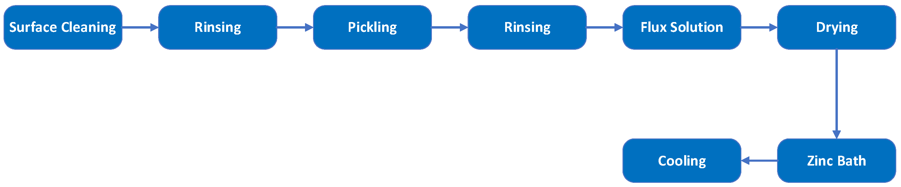
4.2.2. Galvanized Steel Wires

Galvanized wires are the predominant choice for the core of conventional overhead conductors, especially ACSR conductors. The galvanization process is a conventional method used to protect ferrous metals against corrosion. This process involves several sequential stages: cleaning, rinsing, pickling, rinsing again, applying a flux solution, drying, immersing in a zinc bath, and subsequent cooling. The zinc bath temperature can reach up to 450 °C. Proper surface preparation is crucial, as inadequate cleaning can result in an uneven, discontinuous surface texture unsuitable for use in overhead conductors [71,72]. The continuous hot-dip galvanizing process is shown in Figure 2. Key parameters for quality galvanizing include surface pretreatment, dipping techniques, and post-treatment [73]. Cracking in the zinc coating, peeling, and poor adhesion are primary defects in continuous hot-dip galvanizing. Recent findings indicate that these issues can be minimized by optimizing the zinc bath temperature, adjusting the immersion time, and carefully controlling the cooling rates [74]. Alloying elements such as C, Si, P, and Mn can affect the galvanized coating by influencing the growth of the Fe-Zn phase [75]. Elevated carbon content accelerates the dissolution rate of iron into the melt, leading to a fragile and unstable ζ phase coating [72,76]. To enhance bonding between the zinc and the steel substrate, a small amount of aluminum (approximately 0.05 wt. % to 0.25 wt. %) may be added to the mixture [77]. The zinc bath temperature significantly affects the coating thickness, varying between 450 °C and 530 °C. Verma et al. [78] found the highest coating thickness at 530 °C, while Biaco et al. reported maximum thickness at 480 °C. However, the ζ phase formed at these temperatures is often incoherent and unstable, making it unsuitable for industrial use [75]. The zinc coating on steel core wires limits high-temperature operation. Above 200 °C, the coating’s adhesion weakens, reducing corrosion resistance and lifespan due to pitting. Over 225 °C, zinc can alloy with steel, forming brittle compounds that flake off, further reducing corrosion resistance and increasing fatigue susceptibility [70].

4.2.3. Galfan-Coated Steel Wires

Galfan-coated steel wires are used in the core of overhead conductors. The production process of Galfan-coated steel wires is similar to that of galvanized steel wires, with the primary difference being their chemical compositions. While galvanized coatings are predominantly zinc, Galfan coatings contain about 5% aluminum, enhancing their anti-corrosive properties. Additionally, a small amount of mischmetal, including rare-earth elements like cerium and lanthanum, is added to improve flowability and wettability. Galfan coatings offer significant advantages such as ductility, impressive corrosion resistance, and a reduction in bare spots. These attributes make Galfan-coated wires an excellent choice for applications requiring robust corrosion resistance [79]. Unlike the typical hot-dipped galvanizing process, this unique coating is specifically applied to the core wires to endure extended operational temperatures of up to 300 °C, allowing conductor temperatures around 250 °C [70]. Galfan-coated wires are advantageous in scenarios necessitating enhanced corrosion resistance and long-term durability at high operational temperatures. Key factors in the Galfan coating process include surface pretreatment, flux type, Galfan bath composition, and post-treatment. After coating, aluminum wires are stranded around the steel core to complete the conductor, followed by a final inspection. Figure 3 provides a visual representation of the production process.

5. Performance Characteristics and Environmental Behavior of ACSS Conductors

5.1. Current-Carrying Capacity and Transmission Losses

ACSS conductors are engineered to increase the maximum current-carrying capacity of transmission lines by enabling operation at elevated temperatures, reaching up to 250 °C, while maintaining their structural strength [80]. The steel core of ACSS conductors supports the mechanical load, allowing the aluminum strands to operate effectively at high temperatures without a significant reduction in tensile strength. This design mitigates the sag commonly observed during high-temperature operation, thereby maintaining required clearances and improving overall system reliability. In addition, trapezoidal wires can be used in ACSS conductors, which reduces the diameter of the conductor, resulting in lower wind and ice loads. This, in turn, increases the current-carrying capacity and reduces transmission losses. ACSS conductors have excellent thermal stability, allowing them to maintain optimal conductivity even under high-temperature conditions. This characteristic enables ACSS conductors to effectively handle increased power loads, resulting in reduced resistive losses and improved power transmission efficiency [53].

5.2. Creep Behavior

Conductor creep refers to the permanent stretching of a conductor caused by pulling forces, leading to increased sag. Safety margins are necessary to ensure adequate ground clearance throughout the conductor’s lifespan. Creep can be categorized into two types: geometrical settlement and metallurgical deformation [81]. Geometrical settlement occurs due to high conductor tensions during severe weather conditions. When strands draw closer, plastic deformation happens at the points where strands from different layers intersect or contact each other [82]. This phenomenon primarily affects soft metals like aluminum and impacts the entire conductor. Although this type of creep is not time-dependent, it occurs within the first hour of high tension. Prolonged high tension leads to metallurgical deformation instead [81,83]. Metallurgical deformation results from mechanical and thermal stress over time [82,84]. There are two forms: normal-temperature (long-term) creep and elevated-temperature creep. Elevated-temperature creep occurs rapidly during emergency high-temperature conditions, impacting untreated aluminum alloys used in conductors. Pre-tensioning effectively eliminates long-term creep in ACSS conductors [70,81]. Traditional conductors undergo long-term creep, whereas ACSS conductors do not exhibit creep during their service life. This is because all stress within the aluminum quickly transfers to the steel core during operation. Consequently, aluminum creep does not affect the ultimate sag of ACSS conductors. The steel core has an exceedingly minimal long-term creep rate, negligible under normal stress conditions [53]; therefore, creep is not a factor for ACSS conductors [85]. The phenomenon of creep in overhead conductors leads to several critical issues, such as an increase in sag, which can compromise safety clearances, and a decrease in tension, which affects mechanical stability. Continuous creep also reduces the strength of the conductor, making it more susceptible to external stresses such as wind or ice. Conductor creep can be mitigated by two methods, pre-tensioning [83] and over-tensioning [86]. Pre-tensioning refers to the temporary application of tension to the conductor prior to installation, which helps prevent early creep. Studies show that since ACSS conductors have annealed aluminum wires, pre-tensioning can be very beneficial and removes most of the geometrical settlement before the final clamping. This is because, after aluminum creep occurs, the tensile stresses in the conductor are transferred to the core [81]. On the other hand, over-tensioning involves installing the conductor at a higher tension level to compensate for future creep. These approaches are often used together to maximize efficacy, especially for HTLS conductors. These conductors must be carefully managed to ensure that stress is evenly distributed among their components, resulting in long-term stability and performance. Despite ACSS conductors operating at high temperatures, there are no specific standard test methods for evaluating creep at high temperatures for them. Developing a dedicated testing standard is necessary to understand the creep behavior of ACSS conductors better.

5.3. Stress–Strain

A stress–strain test can be conducted on both the complete conductor and the steel core individually to evaluate the tensile characteristics of the conductor. This test adheres to the guidelines outlined in the BS EN 50540 standard [55]. The procedure involves applying varying loads and employing different load-holding durations. The results from tensile stress–strain tests provide a visual representation of how different conductors, commonly employed in bare overhead transmission lines, actually perform under tension. These tests also reveal how certain factors, such as repeated stressing and the cable’s lay (the arrangement of individual wires in the cable), influence the behavior of these conductors [87]. By repeating this process, a stress–strain curve is generated, allowing for the determination of the conductor’s tensile behavior, as well as the initial and ultimate moduli [55].

5.4. Short-Circuit Current

A short circuit can result from excessive current flow, accidental incidents, equipment failures, insulation breakdowns, or adverse weather conditions. This event causes a massive surge in electric current, leading to power outages, damaged circuit devices, fire hazards, and explosions. The excessive heat generated can cause overcurrent flow, rapidly increasing the conductor’s temperature. In aluminum wires, this can lead to a phenomenon called “bird caging”, where wires become distorted and twisted. Proper safety measures and preventive maintenance are crucial to mitigate these risks [88]. During a short-circuit test, conductor temperature difference (initial and final) can be of approximately 60 °C [89]. The short-circuit test is a crucial assessment conducted on an HTLS conductor that is subjected to a short-circuit current for a specified duration [90,91]. The test measures the conductor’s thermal performance, including its resistance to overheating and potential damage caused by the generated heat. This information is vital for determining the conductor’s suitability for real-world applications, ensuring its reliability and safety in power transmission systems [92]. As there are no specific standard test methods for the short-circuit test of ACSS conductors, the short-circuit test method used for ACSS conductors is IEC 60794, which is designed for optical ground wire (OPGW) conductors. A dedicated short-circuit test method for ACSS conductors is needed.

5.5. Electrical Resistance

5.5.1. DC Electrical Resistance

The direct current (DC) resistance of the entire conductor is determined by several factors, including the quantity of aluminum and steel wires, the cross-sectional area of each wire, the respective electrical resistivity of aluminum and steel, the prevailing temperature, and the increase in resistance due to the stranding process. Since electrical resistance is temperature-dependent, the DC resistance should be specified at 20 °C. The DC resistance per unit length of the conductor can be calculated using Pouillet’s law. The electrical resistance of all aluminum strands of unit length is as follows:
R A l = r A l N A l × P A l
where N A l is the number of aluminum wires used in the conductor, and P A l is the stranding increment of aluminum strands due to stranding given in ASTM and BS EN [55,93,94]. The electrical resistance of all aluminum strands is as follows:
R s t = r s t N s t × P s t
where N s t is the number of steel wires in the conductor’s core, and P s t is the stranding increment of steel wires due to stranding and given in ASTM and BS EN [55,93,94]. As the outer aluminum strands and the inner steel core are parallel, the overall conductor’s electrical resistance of unit length will be as follows:
R D C = R A l × R s t R A l + R s t
If the electrical resistance at any other temperature ( T 2 ) than 20 °C is needed, it can be calculated as follows:
R D C T 2 = R 20   ° C × 1 + α T 2 20
where α is the temperature coefficient of resistivity, which depends on the type of material.

5.5.2. AC Electrical Resistance

While the DC electrical resistance is determined in a specific temperature ( T ) , the AC electrical resistance can be obtained in that temperature. First, the X value shall be determined as follows:
X = 0.4497 R ( T ) D C
Then, based on the obtained X value, the corresponding K values determined according to the K X table found in [95], and finally using the following equation, the corresponding AC resistance is calculated using the following formula:
R T A C = K × R T D C

5.6. Self-Damping Behavior

As conductors flex, internal movement between strands generates functional forces that contribute to damping [81,96]. Metallurgical damping within the core and individual strands further adds to this effect. Combined, these dissipative mechanisms form conductor self-damping, crucial for absorbing energy during aeolian vibrations [97]. Increased conductor tension reduces strand slippage, lowering self-damping and potentially intensifying aeolian vibrations, thereby raising fatigue risks. Maintaining lower tensions helps mitigate this effect. Frequency and magnitude of vibration also impact self-damping [98], with research showing larger conductors dissipate more power. Trapezoidal conductors tend to dissipate more power at moderately high frequencies (>20 Hz) compared to similarly sized ACSR conductors [99]. As the load is totally transferred to the core after reaching the knee point temperature, the self-damping of ACSS conductors improves at higher operating temperatures [81]. The absence of studies concerning self-damping of ACSS conductors poses a challenge within this field.

5.7. Current–Temperature Calculation

The temperature and current-carrying capacity of conductors are correlated and influenced by environmental factors such as wind speed, direction, ambient temperature, precipitation, and solar radiation. Transmission line power transfer capacity is limited by stability, voltage, and thermal constraints, with thermal limits being crucial for safety and reliability. Elevated conductor temperatures reduce their current-carrying ability, making it important to forecast and simulate this correlation. Understanding conductor heating and cooling processes is vital, as higher wind speeds increase transmission capacity by cooling distribution lines [100,101,102]. Techniques used to calculate the current–temperature relationship are essential tools for determining how much electrical current overhead conductors can safely carry at their designated operating temperature. These methods also serve as a basis for estimating factors like sag performance, creep, annealing rate, and tensile strength reduction. Inaccuracies in these calculations can impact these factors. Several physical phenomena affect current–temperature calculations in overhead conductors, including Joule heating, solar heating, corona heating, and cooling mechanisms like convective, radiative, and evaporative cooling [103,104]. Joule heating occurs when an electric current generates thermal energy within a conductor. Solar heating results from the conductor absorbing heat from the sun’s magnetic wavelengths. Corona heating adds thermal energy due to partial discharge in the ionized air near the conductor’s surface. Convective cooling transfers heat from the conductor’s surface via wind, influenced by the Reynolds number. Radiative cooling emits heat from the conductor as electromagnetic waves [103]. Evaporative cooling happens when water on the conductor’s surface evaporates, cooling the conductor [105]. Each of these mechanisms can be modeled using different approaches. From the heat balance, the temperature and the maximum electrical-current-carrying capacity can be determined. The heat balance equation is as follows:
P J + P S + P i H e a t i n g = P C + P R + P w C o o l i n g
The heating mechanisms of Joule heating, solar heating, and corona heating are denoted as P J , P S , and P i , respectively. On the other hand, the cooling mechanisms of convective cooling, radiative cooling, and evaporative cooling are represented by P C , P R , and P w , respectively. These mechanisms can be modeled by various standards and approaches, such as those by IEEE, IEC, and Cigre [106,107].

5.8. Corona Effect

Corona is a non-linear phenomenon occurring during the initial stage of electrical discharges, where electric current passes from a conductor to the ionized surrounding medium [108]. This involves localized discharges near electrode surfaces with intense electric fields, challenging the insulating capabilities of the surrounding dielectric medium. First meticulously examined by Faraday in 1838, the corona phenomenon releases electrical energy when the electric field around a conductor ionizes the neighboring air, creating a halo or visible glow [109]. Corona discharge in transmission lines can produce audible hissing sounds and the distinctive scent of ozone, generated through the breakdown and recombination of O2 molecules. The glow’s appearance and arrangement depend on the phase of the AC signal at any specific point in time [110]. Both microscopic and macroscopic approaches can study and simulate corona. High voltage in overhead power lines can induce corona discharge, increasing energy dissipation due to line design and operational factors. Higher voltages can exceed air’s insulation capacity near conductors, causing localized discharge and potentially increasing losses per unit length (p.u.l.) [111]. While often seen as undesirable, the corona effect can be beneficial during lightning-induced surges, reducing peak traveling wave values and slowing their propagation by enhancing line capacitance, thus protecting critical electrical devices and improving system resilience against transient overvoltages [112]. Li et al. [113] studied the effect of water droplet sizes on corona inception and conductor vibration relative to power frequency phases, noting that uniform, stable droplets synchronize vibration and corona emissions over extended lengths. Xin Qi et al. [114] examined surface contaminants like kaolin, NaCl, and carbon, finding that uniform coatings weaken corona discharge by reducing dielectric barrier discharge intensity and surface electric field. Contaminants increase onset voltage and decrease photon counting rate, DC electric field, and ion current density, with electrically conductive contaminants having a smaller impact compared to coating thickness. Jiahui Zhu et al. [115] investigated how conductor surface morphologies under positive DC voltages affect corona behavior, discovering that higher voltage and longer testing create distinctive surface patterns, increasing roughness and enhancing corona discharge. Pei Xu et al. [116] applied a TiO2 coating using plasma spraying on conductor surfaces, improving surface quality and reducing roughness (Ra). However, while bare wire surfaces remained stable, coated surfaces degraded due to photocatalysis facilitated by the electric field, despite overall improvement in surface quality. Megala et al. [117] found that wet conductor surfaces have a higher corona inception voltage compared to dry surfaces, using an indoor corona cage. Increasing the conductor diameter helps mitigate corona loss. DC transmission lines exhibit lower corona loss than high-voltage AC lines due to higher material conductivity, which reduces corona effects.

5.9. Sag–Temperature Behavior

Once the conductor is under operational stress or pre-stressed during installation, its sag primarily depends on the length changes in the steel core due to temperature fluctuations. The sag of a conductor can be estimated using mathematical models. For a conductor installed between two level spans that are relatively close, the sag can be approximated by the following parabolic equation [118]:
D = w S 2 8 H
where D is the sag of the conductor, S is the span length, w is the weight of the conductor per unit length, and H is the horizontal component of the tension force. In non-uniform conductor designs, where the core material differs from the outer layers, the conductor heats up under various electrical loads. The difference in the thermal expansion coefficient between the core and the aluminum strands causes changes in tensile load distribution. As the temperature increases, the aluminum strands elongate more than the core, relaxing and transferring tensile load to the core. At a certain temperature, known as the knee point temperature (KPT), the tension on the aluminum strands is entirely transferred to the core, leaving no tensile load on the aluminum wires [119]. Due to the high tension experienced by the steel core within ACSS conductors, the reduction in tension force at elevated temperatures is minimal compared to ACSR conductors, resulting in lower overall sag. Moreover, as the KPT of ACSS is lower than that of ACSR due to the use of annealed aluminum strands, the sag response of an ACSS conductor is predominantly governed by the thermal characteristics of its steel core. The lower coefficient of thermal expansion of the steel core relative to the aluminum strands results in ACSS conductors exhibiting less sag at elevated temperatures than ACSR conductors. As a result, the sag–temperature gradient of an ACSS conductor is significantly less than that of an ACSR conductor of equivalent cross-sectional area [85,120].

5.10. Lightning Resistance

Lightning is a major cause of interruptions in overhead transmission lines in many countries [121]. Lightning strikes generate transient voltages that can exceed thermal limits, causing supply disruptions. Strikes exhibit peak currents ranging from 2 kA to 200 kA, with a 40 kA strike reaching temperatures of about 30,000 K and releasing 39.55 × 10³ J/Ω within microseconds [122]. When lightning strikes the upper conductor, it induces a high surge in current, potentially burning through the conductor’s outer layer. In shielding failure, lightning can bypass ground wires and directly strike phase conductors. The lightning current then splits into two, traveling in opposite directions along the transmission line, threatening system integrity [123]. To reduce lightning-induced trip-outs, several measures can be taken: incorporating ground wires, minimizing tower grounding impedance, increasing the Basic Lightning Insulation Level (BIL) of components, introducing underbuilt wires, and deploying line arresters [121].

5.11. Galloping

Ice formation on the conductor surface creates an imbalance, leading to aerodynamic instability. This imbalance lowers the natural frequency of the conductor, and when it aligns with a lower natural frequency for vertical vibrations, it triggers galloping [124]. Galloping is a wind-induced oscillation characterized by low frequency and high amplitude, affecting both individual and bundled conductors [125]. These oscillations, typically vertical, range from 0.1 to 1.0 times the sag between supports and vary in frequency depending on the line construction and oscillation mode. Galloping imposes elevated dynamic stresses on cables and support towers, causing mechanical damage such as loosening and expulsion of tower bolts, erosion of landing bolts, deformation of holes, and misalignment of tower pivots and connected components. Prolonged galloping induces fatigue in conductors and the steel framework of towers [125]. Methods to reduce power line vibrations include torsional devices, disrupting ice accretion and aerodynamic uniformity, mechanical dampers, de-spacing, rotating-clamp spacers, and optimized suspension and anchoring designs [124,125,126,127].

5.12. Aeolian Vibrations

Aeolian vibrations arise from the shedding of vortices when an object is exposed to laminar or turbulent flow [128]. In overhead transmission lines, wind-induced vortices cause vibrations within a 5 to 100 Hz frequency range, sometimes reaching amplitudes as large as the conductor’s diameter. These vibrations can cause significant damage and lead to conductor failure due to material fatigue, depending on wind conditions and the conductor’s geometrical and physical properties [98,129]. Accurate vibration assessments require a thorough understanding of wind data, wind power inputs, and the mechanical characteristics of conductors and damper components. To mitigate aeolian vibrations and extend conductor lifespan, various dampers, such as Stockbridge-type dampers, are used [130,131]. Analyzing the thermal and vibration characteristics of HTLS conductors is challenging due to significant differences between the core and outer layers. The core’s low thermal expansion and the distinct aluminum types and strand shapes of the outer layers contribute to these challenges. The installation, operation, and environmental conditions of the power line influence these complexities. HTLS conductors dissipate more power across the vibration frequency range, reducing the detrimental impacts of aeolian vibrations [132].

5.13. Fretting Fatigue

Fretting fatigue significantly threatens transmission line reliability, particularly at constrained points such as suspension clamps. Fretting fatigue is a complex process influenced by several factors, including normal contact load, amplitude of relative slip, coefficient of friction, surface conditions, contact materials, and environmental conditions. It results from the interaction of wear, corrosion, and fatigue phenomena driven by microslips at the contact surface and cyclic local stresses. Higher contact loads and increased slip amplitudes can exacerbate stress concentrations, while the friction coefficient affects stress distribution and heat generation. Surface roughness and material properties also play a critical role, with harsher environments accelerating material degradation. Together, these factors contribute to crack initiation and propagation, leading to material failure under cyclic loading conditions such as wind-induced vibrations [133]. Extensive research, including field studies, laboratory experiments, and simulations, has shown that fretting significantly contributes to fatigue-related failures in transmission line conductors [134,135,136,137,138,139,140,141,142,143,144,145]. Engineers and maintenance personnel must be aware of fretting issues and implement preventive measures to ensure the safe and reliable operation of these critical infrastructure components. Fatigue life predictions use S-N curves [139,143,146,147], and research indicates that higher conductor tensile strength increases fretting fatigue [139]. Additionally, even a small increase in mean stress significantly decreases fatigue life [143], highlighting the importance of considering tensile conditions in transmission line design and installation. While numerous studies have investigated fretting fatigue in ACSR and AAAC conductors, there is a notable lack of research on ACSS conductors. Interestingly, some studies have shown that annealed aluminum near the temper O condition exhibits an initial increase in fatigue life during the early stages of fatigue testing. This phenomenon has been attributed to an increase in dislocation density within the material. However, unlike strain-hardened aluminum wires, annealed aluminum wires typically exhibit lower overall fatigue resistance. This is likely because the annealing process reduces the strain-hardening effects known to be associated with improved fatigue strength. As a result, aluminum wires that have undergone strain hardening generally exhibit superior fatigue life performance compared to their annealed counterparts [144,148]. This suggests that the fatigue life of ACSS conductors may be less than that of ACSR conductors because ACSS conductors use annealed aluminum wires. Additionally, considering that fatigue failures typically occur in the aluminum strands rather than the steel core [85], this further contributes to the potential reduction in fatigue life for ACSS conductors.
Table 4 compares the key properties of ACSS with those of conventional ACSR conductors of the same outer diameter.

6. Environmental Effects and Sustainable Development

ACSS conductors offer advantages such as lower sag, higher ampacity, and a higher safety factor [151,152]. They are particularly suitable for reconductoring applications. Research shows that replacing HTLS conductors (including ACSS) with existing ACSR conductors significantly reduces environmental impacts compared to building new lines. Benefits include lower fossil fuel use, reduced greenhouse gas emissions, and less noise pollution. Additionally, less cement consumption contributes to reduced CO2 emissions. Establishing new lines requires maintaining a protection corridor, leading to deforestation [153]. HTLS conductors, including ACSS, reduce line losses due to the enhanced electrical conductivity of annealed aluminum, thus decreasing fuel consumption and greenhouse gas emissions. This supports clean energy delivery and aligns with emissions reduction initiatives [3]. A life cycle assessment (LCA) on electrical grids indicates that power losses dominate climate change impacts, followed by metal production for masts and conductors [154,155]. Reconductoring with ACSS can reduce these impacts due to their higher capacity. However, potential drawbacks include increased power losses and safety risks like fires from higher operating temperatures. The lack of a comprehensive LCA for ACSS conductors highlights the need for research on their environmental impacts throughout their life cycles.

7. Conclusions

This study extensively examined ACSS conductors to enhance their technical characteristics, focusing on efficiency in long-distance power transmission with minimal energy loss and resilience against environmental factors such as creep, corona, and sag. Manufacturing procedures for various ACSS conductors were detailed. The electrical, thermal, and mechanical behaviors and tests of ACSS conductors were introduced. The research identified existing deficiencies and standards, providing valuable insights for designers, researchers, and practitioners in power transmission projects. The primary objective was to improve the performance and dependability of ACSS conductors in power transmission applications.

8. Identified Challenges and Research Needs

Extensive research is needed on nano-coatings for developing superhydrophobic surfaces with stability at high temperatures, including the following areas:
  • Investigating the impact of various alloying elements on aluminum alloys’ mechanical and electrical properties at high temperatures is imperative;
  • Examining aging, fatigue, and corrosion of ACSS conductors with different configurations at high temperatures is essential;
  • Specialized investigation is required to understand how alloying elements affect steel alloys’ mechanical and electrical properties under high temperatures;
  • Developing specific standards for short-circuit tests on ACSS conductors is crucial, given the current IEC 60794 standard is tailored for OPGW conductors;
  • A comparative study assessing ACSS conductors versus other high-capacity conductors should include techno-economic analysis and losses;
  • Developing a dedicated standard test method to evaluate creep at high temperatures is essential;
  • Research on industrial-scale removal of impurities from aluminum melts is needed to enhance aluminum’s mechanical and electrical properties;
  • Selecting and incorporating suitable alloys into aluminum should be followed by a thorough examination of creep, fatigue, aging, and sag under high-temperature conditions, especially for novel ACSS conductors;
  • Comprehensive investigations are needed to understand the corrosion, creep, and fatigue behaviors of ACSS conductors with different core materials at high temperatures;
  • Evaluating ACSS conductors that have been in service for extended periods at high temperatures should include assessments of physical, mechanical, and electrical properties, as well as corrosion, fatigue, creep, and aging characteristics;
  • Further research is required on the mechanical, electrical, and thermal behavior of ACSS conductors and the development of specialized standards, given limited existing resources;
  • Research on the self-damping characteristics of ACSS conductors is needed due to the lack of comprehensive studies in this domain;
  • Addressing environmental impacts and promoting sustainable development of ACSS and other overhead conductors requires exhaustive life cycle investigations and comparative assessments with traditional ACSR and various HTLS conductors.

Author Contributions

Conceptualization, M.J., J.-R.R. and P.P.; validation, M.J., J.-R.R. and P.P.; investigation, M.J. and P.P.; resources, P.P.; writing—original draft preparation, M.J.; writing—review and editing, M.J., P.P. and J.-R.R.; supervision, J.-R.R.; project administration, M.J. All authors have read and agreed to the published version of the manuscript.

Funding

This research was funded by the Generalitat de Catalunya under grant number 2021 SGR 00392 and by Ministerio para la Transformación Digital y de la Función Pública under grant number PID2023-147016OB-I00.

Conflicts of Interest

Author Milad Jalilian was employed by the company Pooya Power Knowledge Enterprise. The remaining authors declare that the research was conducted in the absence of any commercial or financial relationships that could be construed as a potential conflict of interest.

References

  1. Kyriakopoulos, G.L.; Arabatzis, G. Electrical energy storage systems in electricity generation: Energy policies, innovative technologies, and regulatory regimes. Renew. Sustain. Energy Rev. 2016, 56, 1044–1067. [Google Scholar] [CrossRef]
  2. Nuchprayoon, S.; Chaichana, A. Performance comparison of using ACSR and HTLS conductors for current uprating of 230-kV overhead transmission lines. In Proceedings of the 2018 IEEE International Conference on Environment and Electrical Engineering and 2018 IEEE Industrial and Commercial Power Systems Europe (EEEIC/I&CPS Europe), Palermo, Italy, 12–15 June 2018; IEEE: Piscataway, NJ, USA, 2018; pp. 1–5. [Google Scholar]
  3. Riba, J.-R.; Bogarra, S.; Gómez-Pau, Á.; Moreno-Eguilaz, M. Uprating of transmission lines by means of HTLS conductors for a sustainable growth: Challenges, opportunities, and research needs. Renew. Sustain. Energy Rev. 2020, 134, 110334. [Google Scholar] [CrossRef]
  4. Kavanagh, T.; Armstrong, O. An evaluation of High Temperature Low Sag conductors for uprating the 220 kV transmission network in Ireland. In Proceedings of the 45th International Universities Power Engineering Conference UPEC2010, Cardiff, UK, 31 August–3 September 2010; IEEE: Piscataway, NJ, USA, 2010; pp. 1–5. [Google Scholar]
  5. Filippone, G.; Ippolito, M.; Massaro, F.; Puccio, A. On the roadmap to Supergrid in Sicily: LIDAR technology and HTLS conductors for uprating the 150 kV lines. In Proceedings of the IEEE PES Innovative Smart Grid Technologies, Europe, Washington, DC, USA, 19–22 February 2014; IEEE: Piscataway, NJ, USA, 2014; pp. 1–5. [Google Scholar]
  6. Mateescu, E.; Marginean, D.; Florea, G.; St IA, G.; Matea, C. Reconductoring Using HTLS Conductors. Case study for a 220 kV double circuit transmission LINE in Romania. In Proceedings of the 2011 IEEE PES 12th International Conference on Transmission and Distribution Construction, Operation and Live-Line Maintenance (ESMO), Providence, RI, USA, 16–19 May 2011; IEEE: Piscataway, NJ, USA, 2011; pp. 1–7. [Google Scholar]
  7. Glaum, P.; Hofmann, F. Leveraging the existing German transmission grid with dynamic line rating. Appl. Energy 2023, 343, 121199. [Google Scholar] [CrossRef]
  8. Daminov, I.; Blavette, A.; Bourguet, S.; Ahmed, H.B.; Soulard, T.; Warlop, P. Economic performance of an overplanted offshore wind farm under several commitment strategies and dynamic thermal ratings of submarine export cable. Appl. Energy 2023, 346, 121326. [Google Scholar] [CrossRef]
  9. Safari, N.; Mazhari, S.; Chung, C.; Ko, S. Secure probabilistic prediction of dynamic thermal line rating. J. Mod. Power Syst. Clean Energy 2021, 10, 378–387. [Google Scholar] [CrossRef]
  10. Rashkovska, A.; Jančič, M.; Depolli, M.; Kosmač, J.; Kosec, G. Uncertainty assessment of dynamic thermal line rating for operational use at transmission system operators. IEEE Trans. Power Syst. 2022, 37, 4642–4650. [Google Scholar] [CrossRef]
  11. Riba, J.-R.; Liu, Y.; Moreno-Eguilaz, M.; Sanllehí, J. On-Line Core Losses Determination in ACSR Conductors for DLR Applications. Materials 2022, 15, 6143. [Google Scholar] [CrossRef]
  12. Moradi-Sepahvand, M.; Amraee, T. Secure expansion of energy storage and transmission lines considering bundling option under renewable penetration. Appl. Energy 2023, 347, 121414. [Google Scholar] [CrossRef]
  13. Wang, Y.; Wang, Y.; Dong, X.; Wang, C.; Feng, T.; Che, C.; Lu, T. Capacity assessment for wind-storage integration system considering electro-thermal coupling of overhead transmission line. IEEE Trans. Power Syst. 2023, 39, 967–975. [Google Scholar] [CrossRef]
  14. Lai, C.-M.; Teh, J. Network topology optimisation based on dynamic thermal rating and battery storage systems for improved wind penetration and reliability. Appl. Energy 2022, 305, 117837. [Google Scholar] [CrossRef]
  15. Long, Q.; Liu, J.; Ren, C.; Yin, W.; Liu, F.; Hou, Y. Two-Stage Submodular Optimization of Dynamic Thermal Rating for Risk Mitigation Considering Placement and Operation Schedule. IEEE Trans. Power Syst. 2023, 39, 3059–3074. [Google Scholar] [CrossRef]
  16. Chen, H.; Xiong, R.; Lin, C.; Shen, W. Model predictive control based real-time energy management for hybrid energy storage system. CSEE J. Power Energy Syst. 2020, 7, 862–874. [Google Scholar]
  17. Zhou, M.; Yan, J. A new solution architecture for online power system analysis. CSEE J. Power Energy Syst. 2018, 4, 250–256. [Google Scholar] [CrossRef]
  18. Grigsby, L.L. Electric Power Generation, Transmission, and Distribution; CRC Press: Boca Raton, FL, USA, 2007. [Google Scholar]
  19. Beryozkina, S. Evaluation study of potential use of advanced conductors in transmission line projects. Energies 2019, 12, 822. [Google Scholar] [CrossRef]
  20. Yasaranga, H.; Wijayapala, W.; Hemapala, K. Techno economic analysis of the use of high temperature low sag (HTLS) conductors in the Sri Lanka’s transmission system. Eng. J. Inst. Eng. Sri Lanka 2017, 50, 41–52. [Google Scholar] [CrossRef]
  21. Kachhadiya, A.; Sheth, C.; Gupta, V.; Darji, K. Study and Analysis of HTLS Conductors for Increasing the Thermal Loading of 220 kV Transmission Line. In Proceedings of the Advances in Electric Power and Energy Infrastructure: Proceedings of ICPCCI 2019, Gujarat, India, 4–5 July 2019; Springer: Berlin/Heidelberg, Germany; pp. 229–238. [Google Scholar]
  22. Kishore, T.; Singal, S.K. Optimal economic planning of power transmission lines: A review. Renew. Sustain. Energy Rev. 2014, 39, 949–974. [Google Scholar] [CrossRef]
  23. Kalair, A.; Abas, N.; Khan, N. Comparative study of HVAC and HVDC transmission systems. Renew. Sustain. Energy Rev. 2016, 59, 1653–1675. [Google Scholar] [CrossRef]
  24. Conseil international des grands réseaux électriques. Guide for Qualifying High Temperature Conductors for Use on Overhead Transmission Lines; CIGRÉ: Paris, France, 2010. [Google Scholar]
  25. Papailiou, K.O. Overhead Lines. CIGRE Green Books; Springer: Cham, Switzerland, 2017. [Google Scholar] [CrossRef]
  26. Kenge, A.V.; Dusane, S.V.; Sarkar, J. Statistical analysis & comparison of HTLS conductor with conventional ACSR conductor. In Proceedings of the 2016 International Conference on Electrical, Electronics, and Optimization Techniques (ICEEOT), Chennai, India, 3–5 March 2016; IEEE: Piscataway, NJ, USA, 2016; pp. 2955–2959. [Google Scholar]
  27. Qiao, K.; Zhu, A.; Wang, B.; Di, C.; Yu, J.; Zhu, B. Characteristics of heat resistant aluminum alloy composite core conductor used in overhead power transmission lines. Materials 2020, 13, 1592. [Google Scholar] [CrossRef]
  28. Bartos, M.; Chester, M.; Johnson, N.; Gorman, B.; Eisenberg, D.; Linkov, I.; Bates, M. Impacts of rising air temperatures on electric transmission ampacity and peak electricity load in the United States. Environ. Res. Lett. 2016, 11, 114008. [Google Scholar] [CrossRef]
  29. Adams, H.W. Steel supported aluminum conductors (SSAC) for overhead transmission lines. IEEE Trans. Power Appar. Syst. 1974, 5, 1700–1705. [Google Scholar] [CrossRef]
  30. Thrash, F. ACSS/TW-an improved conductor for upgrading existing lines or new construction. In Proceedings of the 1999 IEEE Transmission and Distribution Conference (Cat. No. 99CH36333), New Orleans, LO, USA, 11–16 April 1999; IEEE: Piscataway, NJ, USA, 1999; pp. 852–857. [Google Scholar]
  31. Zame, K.K.; Brehm, C.A.; Nitica, A.T.; Richard, C.L.; Schweitzer III, G.D. Smart grid and energy storage: Policy recommendations. Renew. Sustain. Energy Rev. 2018, 82, 1646–1654. [Google Scholar] [CrossRef]
  32. Kabeyi, M.J.B.; Olanrewaju, O.A. Sustainable energy transition for renewable and low carbon grid electricity generation and supply. Front. Energy Res. 2022, 9, 1032. [Google Scholar] [CrossRef]
  33. Knych, T.; Piwowarska, M.; Uliasz, P. Studies on the process of heat treatment of conductive AlZr alloys obtained in various productive processes. Arch. Metall. Mater. 2011, 56, 685–692. [Google Scholar] [CrossRef]
  34. Orlova, T.; Mavlyutov, A.; Latynina, T.; Ubyivovk, E.; Murashkin, M.Y.; Schneider, R.; Gerthsen, D.; Valiev, R. Influence of severe plastic deformation on microstructure, strength and electrical conductivity of aged Al–0.4 Zr (wt.%) alloy. Rev. Adv. Mater. Sci. 2018, 55, 92–101. [Google Scholar] [CrossRef]
  35. Orlova, T.; Latynina, T.; Mavlyutov, A.; Murashkin, M.; Valiev, R. Effect of annealing on microstructure, strength and electrical conductivity of the pre-aged and HPT-processed Al-0.4 Zr alloy. J. Alloys Compd. 2019, 784, 41–48. [Google Scholar] [CrossRef]
  36. Pasini, C.; Sildva, H.; Gorja, G.; Peter, Z. High temperature current cycle test of implosive connectors on ACSS conductor. In Proceedings of the IEEE PES T&D 2010, New Orleans, LO, USA, 19–22 April 2010; IEEE: Piscataway, NJ, USA, 2010; pp. 1–8. [Google Scholar]
  37. Elder, D.S.; Sekunda, J. Process of Producing Overhead Transmission Conductor. U.S. Patent No. 7,615,127, 10 November 2009. [Google Scholar]
  38. ASTM B233-22; Standard Specification for Aluminum 1350 Drawing Stock for Electrical Purposes. ASTM International: West Conshohocken, PA, USA, 2022.
  39. Alvarez-Antolin, F.; Amghouz, Z.; Cofiño-Villar, A.; Gonzalez-Pociño, A.; Melero, M.G. Decrease in Electrical Resistivity below 28 nΩm by Aging in Hyperperitectic Al-Zr Alloys Treated at High Temperatures. Metals 2021, 11, 1171. [Google Scholar] [CrossRef]
  40. Knych, T.; Piwowarska-Uliasz, M.; Uliasz, P. Aluminium alloys with zirconium additions, in the range from 0.05 to 0.32%, intended for applications in the overhead electrical power engineering. Arch. Metall. Mater. 2014, 59, 339–343. [Google Scholar] [CrossRef]
  41. Chao, R.-Z.; Guan, X.-H.; Guan, R.-g.; Di, T.; Chao, L.; Xiang, W.; Zhang, J. Effect of Zr and Sc on mechanical properties and electrical conductivities of Al wires. Trans. Nonferrous Met. Soc. China 2014, 24, 3164–3169. [Google Scholar] [CrossRef]
  42. Zhang, J.; Wang, H.; Yi, D.; Wang, B.; Wang, H. Comparative study of Sc and Er addition on microstructure, mechanical properties, and electrical conductivity of Al-0.2 Zr-based alloy cables. Mater. Charact. 2018, 145, 126–134. [Google Scholar] [CrossRef]
  43. Belov, N.; Alabin, A.; Matveeva, I.; Eskin, D. Effect of Zr additions and annealing temperature on electrical conductivity and hardness of hot rolled Al sheets. Trans. Nonferrous Met. Soc. China 2015, 25, 2817–2826. [Google Scholar] [CrossRef]
  44. Kahveci, O.; Çadirli, E.; Arı, M.; Tecer, H.; Gündüz, M. Measurement and prediction of the thermal and electrical conductivity of Al-Zr overhead line conductors at elevated temperatures. Mater. Res. 2018, 22, e20180513. [Google Scholar] [CrossRef]
  45. Shao, Q.; Elgallad, E.M.; Maltais, A.; Chen, X.-G. Development of thermal-resistant Al–Zr based conductor alloys via microalloying with Sc and manipulating thermomechanical processing. J. Mater. Res. Technol. 2023, 25, 7528–7545. [Google Scholar] [CrossRef]
  46. Erol, H.; Tecer, H.; Acer, E.; Kadioğlu, C.; Gündüz, M. Tensile strength of Al-Zr overhead line conductors. In Proceedings of the Materials Science Forum, Montreal, QC, Canada, 27–31 October 2013; IEEE: Piscataway, NJ, USA, 2013; pp. 793–797. [Google Scholar]
  47. Pozdniakov, A.; Barkov, R.Y. Microstructure and mechanical properties of novel Al-Y-Sc alloys with high thermal stability and electrical conductivity. J. Mater. Sci. Technol. 2020, 36, 1–6. [Google Scholar] [CrossRef]
  48. ASTM B498/B498M-19; Standard Specification for Zinc-Coated (Galvanized) Steel Core Wire for Use in Overhead Electrical Conductors. ASTM International: West Conshohocken, PA, USA, 2019.
  49. ASTM B957/957M-22; Standard Specification for Extra-High-Strength and Ultra-High-Strength Zinc-Coated (Galvanized) Steel Core Wire for Overhead Electrical Conductors. ASTM International: West Conshohocken, PA, USA, 2022.
  50. ASTM B802/B802M-22; Standard Specification for Zinc–5% Aluminum-Mischmetal Alloy-Coated Steel Core Wire for Aluminum Conductors, Steel Reinforced (ACSR). ASTM International: West Conshohocken, PA, USA, 2022.
  51. ASTM B803/B803M-22; Standard Specification for High-Strength Zinc–5% Aluminum-Mischmetal Alloy-Coated Steel Core Wire for Use in Overhead Electrical Conductors. ASTM International: West Conshohocken, PA, USA, 2022.
  52. ASTM B958/B958M-22; Standard Specification for Extra-High-Strength and Ultra-High-Strength Class A Zinc–5% Aluminum-Mischmetal Alloy-Coated Steel Core Wire for Use in Overhead Electrical Conductors. ASTM International: West Conshohocken, PA, USA, 2022.
  53. Karabay, S. ACSS/TW aerial high-temperature bare conductors as a remedy for increasing transmission line capacity and determination of processing parameters for manufacturing. Mater. Des. 2009, 30, 816–825. [Google Scholar] [CrossRef]
  54. BS EN 62004; Thermal-Resistant Aluminium Alloy Wire for Overhead Line Conductor. International Electrotechnical Commission: Geneva, Switzerland, 2009.
  55. BS EN 50540; Conductors for Overhead Lines—Aluminium Conductors Steel Supported (ACSS). International Electrotechnical Commission: Geneva, Switzerland, 2010.
  56. ASTM B502/B502M-19; Standard Specification for Aluminum-Clad Steel Core Wire for Use in Overhead Electrical Aluminum Conductors. ASTM International: West Conshohocken, PA, USA, 2019.
  57. ASTM B609/B609M-12; Standard Specification for Aluminum 1350 Round Wire, Annealed and Intermediate Tempers, for Electrical Purposes. ASTM International: West Conshohocken, PA, USA, 2021.
  58. ASTM B606/B606M-22; Standard Specification for High-Strength Zinc-Coated (Galvanized) Steel Core Wire for Aluminum and Aluminum-Alloy Conductors, Steel Reinforced. ASTM International: West Conshohocken, PA, USA, 2022.
  59. ASTM B941-22; Standard Specification for Heat Resistant Aluminum-Zirconium Alloy Wire for Electrical Purposes. ASTM International: West Conshohocken, PA, USA, 2022.
  60. Properzi, L.a.A.O. Continuous Casting and Rolling by the ‘Properzi’ Method. Wire World Int. 1981, 23, 33–35. [Google Scholar]
  61. Properzi, I. Continuous Casting Machine with Channel Coolant Control Means. U.S. Patent No. 3,626,479, 1971. [Google Scholar]
  62. Dablement, S.; Mortensen, D.; Fjaer, H.; Lee, M.; Grandfield, J.; Savage, G.; Nguyen, V. Modelling of shrinkage cavity defects during the wheel and belt casting process. In Proceedings of the IOP Conference Series: Materials Science and Engineering, Schladming, Austria, 17–22 June 2012; IOP Publishing: Bristol, UK, 2012; p. 012056. [Google Scholar]
  63. Khaliq, A.; Akbar Rhamdhani, M.; Brooks, G.A.; Grandfield, J. Removal of Vanadium from Molten Aluminum—Part III. Analysis of Industrial Boron Treatment Practice. Metall. Mater. Trans. B 2014, 45, 784–794. [Google Scholar] [CrossRef]
  64. Cooper, P.S.; Kearns, M.A. Removal of transition metal impurities in aluminium melts by boron additives. In Materials Science Forum; Trans Tech Publications: Zurich Switzerland, 1996; pp. 141–146. [Google Scholar]
  65. Khaliq, A.; Rhamdhani, M.A.; Brooks, G.A.; Grandfield, J.F. Removal of Vanadium from Molten Aluminum-Part I. Analysis of VB 2 Formation. Metall. Mater. Trans. B 2014, 45, 752–768. [Google Scholar] [CrossRef]
  66. Xu, X.; Feng, Y.; Yang, P.; Zhang, B.; Wang, Y.; Wang, Q.; Fan, X.; Ding, H. The influence of trace elements on the microstructures and properties of the aluminum conductors. Results Phys. 2018, 11, 1058–1063. [Google Scholar] [CrossRef]
  67. Cui, X.; Wu, Y.; Liu, X.; Zhao, Q.; Zhang, G. Effects of grain refinement and boron treatment on electrical conductivity and mechanical properties of AA1070 aluminum. Mater. Des. 2015, 86, 397–403. [Google Scholar] [CrossRef]
  68. Dewan, M.A.; Rhamdhani, M.A.; Mitchell, J.B.; Davidson, C.; Brooks, G.A.; Easton, M.; Grandfield, J.F. Control and removal of impurities from Al melts: A review. In Proceedings of the Materials Science Forum, Columbus, OH, USA, 16–20 October 2011; Trans Tech Publications: Zurich Switzerland, 2011; pp. 149–160. [Google Scholar]
  69. Li, C.; Zhang, T.a.; Liu, J.; Liu, Y. Synergistic solid–liquid composite and rapid solidification preparation of aluminum-clad steel wires. Mater. Des. 2024, 244, 113182. [Google Scholar] [CrossRef]
  70. Transmission and Distribution Committee. IEEE Guide for Determining the Effects of High-Temperature Operation on Conductors, Connectors and Accessories; IEEE Power and Energy Society; IEEE: Piscataway, NJ, USA, 2013. [Google Scholar]
  71. Asgari, H.; Toroghinejad, M.; Golozar, M. Effect of coating thickness on modifying the texture and corrosion performance of hot-dip galvanized coatings. Curr. Appl. Phys. 2009, 9, 59–66. [Google Scholar] [CrossRef]
  72. Shibli, S.; Meena, B.; Remya, R. A review on recent approaches in the field of hot dip zinc galvanizing process. Surf. Coat. Technol. 2015, 262, 210–215. [Google Scholar] [CrossRef]
  73. Hanna, F.; Nassif, N. Factors affecting the quality of hot-dip-galvanized steel sheets. Surf. Technol. 1984, 21, 27–37. [Google Scholar] [CrossRef]
  74. Gelfi, M.; Solazzi, L.; Poli, S. Influence of the Manufacturing Process on Defects in the Galvanized Coating of High Carbon Steel Wires. Materials 2017, 10, 264. [Google Scholar] [CrossRef]
  75. Bicao, P.; Jianhua, W.; Xuping, S.; Zhi, L.; Fucheng, Y. Effects of zinc bath temperature on the coatings of hot-dip galvanizing. Surf. Coat. Technol. 2008, 202, 1785–1788. [Google Scholar] [CrossRef]
  76. Pokorny, P.; Kolisko, J.; Balik, L.; Novak, P. Effect of chemical composition of steel on the structure of hot–Dip galvanized coating. Metalurgija 2016, 55, 115–118. [Google Scholar]
  77. Yeomans, S.R. Galvanized steel reinforcement: Recent developments and future opportunities. In Corrosion of Steel in Concrete Structures; Woodhead Publishing: Sawston, UK, 2023; pp. 161–186. [Google Scholar]
  78. Verma, A.; Van Ooij, W. High-temperature batch hot-dip galvanizing. Part 2. Comparison of coatings formed in the temperature range 520–555 C. Surf. Coat. Technol. 1997, 89, 143–150. [Google Scholar] [CrossRef]
  79. Baboian, R. Corrosion Tests and Standards: Application and Interpretation; ASTM International: West Conshohocken, PA, USA, 2005; Volume 20. [Google Scholar]
  80. Hoffman, S.; Tunstall, M. Maximizing the Ratings of National Grids Existing Transmission Lines Using High Temperature, Low Sag Conductor; CIGRE: Paris, France, 2000; pp. 22–202. [Google Scholar]
  81. Kopsidas, K.; Boumecid, B.; Cooper, I.P. Overhead line design considerations for conductor creep mitigation. IET Gener. Transm. Distrib. 2016, 10, 2424–2432. [Google Scholar] [CrossRef]
  82. Cigre, W. Permanent elongation of conductors. Predictior equation and evaluation methods. Electra 1981, 75, 1–36. [Google Scholar]
  83. Bradbury, J.; Dey, P.; Orawski, G.; Pickup, K. Long-term-creep assessment for overhead-line conductors. In Proceedings of the Institution of Electrical Engineers; IET: London, UK, 1975; pp. 1146–1152. [Google Scholar]
  84. Bradbury, J.; Kuska, G.; Tarr, D. Sag and tension calculations for mountainous terrain. In Proceedings of the IEE Proceedings C (Generation, Transmission and Distribution); IET: London, UK, 1982; pp. 213–220. [Google Scholar]
  85. Global, C. Engineering Transmission Lines with High Capacity Low Sag ACCC Conductors, 1st ed.; CTC Global: Irvine, CA, USA, 2011. [Google Scholar]
  86. Cahill, T. Development of a low-creep ACSR conductor. Wire J. 1973, 6, 66–73. [Google Scholar]
  87. Stickley, G. Stress-strain studies of transmission line conductors. Electr. Eng. 1932, 51, 413. [Google Scholar] [CrossRef]
  88. CIGRE. Guide on Repair of Conductor-Fitting Systems; CIGRE: Paris, France, 2017. [Google Scholar]
  89. Soulinaris, G.; Halevidis, C.; Polykrati, A.; Bourkas, P. Evaluation of the thermal stresses and dielectric phenomena in the investigation of the causes of wildfires involving distribution power lines. Electr. Power Syst. Res. 2014, 117, 76–83. [Google Scholar] [CrossRef]
  90. Wilkins, R.; Saengsuwan, T.; O’Shields, L. Short-circuit tests on current-limiting fuses: Modelling of the test circuit. In Proceedings of the IEE Proceedings C (Generation, Transmission and Distribution); IEEE: Piscataway, NJ, USA, 1993; pp. 30–36. [Google Scholar]
  91. Yusop, F.M.; Masri, S.; Ishak, D.; Kamarol, M. Investigation of Electromagnetic Force in 3P5W Busbar System under Peak Short-Circuit Current. Int. J. Electr. Comput. Eng. 2014, 8, 180–184. [Google Scholar]
  92. Migliori, M.; Lauria, S.; Aluisio, B.; Gadaleta, C.; Carlini, E.M.; Piemonti, L. Series compensation of an uprated 230 kV–50 Hz backbone in central Italy: Impact on fault quantities. In Proceedings of the 2020 55th International Universities Power Engineering Conference (UPEC), Torino, Italy, 1–4 September 2020; IEEE: Piscataway, NJ, USA, 2020; pp. 1–5. [Google Scholar]
  93. ASTM B856-18; Standard Specification for Concentric-Lay-Stranded Aluminum Conductors, Coated Steel Supported (ACSS). ASTM International: West Conshohocken, PA, USA, 2018.
  94. ASTM B857-18; Standard Specification for Shaped Wire Compact Concentric-Lay-Stranded Aluminum Conductors, Coated-Steel Supported (ACSS/TW)1. ASTM International: West Conshohocken, PA, USA, 2018.
  95. AEST. Electrical Transmission and Distribution Reference Book; ABB Power T&D Company, Inc.: Bland, VA, USA, 1997. [Google Scholar]
  96. Hardy, C. Analysis of self-damping characteristics of stranded cables in transverse vibrations. In Proceedings of the CSME Mechanical Engineering Forum 1990, Toronto, ON, Canada, 3–9 June 1990. [Google Scholar]
  97. Std 563-1978; Guide on Conductor Self-Damping Measurements. IEEE: Piscataway, NJ, USA, 1978; p. 0_1.
  98. Vecchiarelli, J. Aeolian Vibration of a Conductor with a Stockbridge-Type Damper. Ph.D. Thesis, University of Toronto, Toronto, ON, USA, 1998. [Google Scholar]
  99. Munaswamy, K.; Haldar, A. Self-damping measurements of conductors with circular and trapezoidal wires. IEEE Trans. Power Deliv. 2000, 15, 604–609. [Google Scholar] [CrossRef]
  100. Michiorri, A.; Nguyen, H.-M.; Alessandrini, S.; Bremnes, J.B.; Dierer, S.; Ferrero, E.; Nygaard, B.-E.; Pinson, P.; Thomaidis, N.; Uski, S. Forecasting for dynamic line rating. Renew. Sustain. Energy Rev. 2015, 52, 1713–1730. [Google Scholar] [CrossRef]
  101. Karimi, S.; Musilek, P.; Knight, A.M. Dynamic thermal rating of transmission lines: A review. Renew. Sustain. Energy Rev. 2018, 91, 600–612. [Google Scholar] [CrossRef]
  102. Fernandez, E.; Albizu, I.; Bedialauneta, M.; Mazon, A.; Leite, P.T. Review of dynamic line rating systems for wind power integration. Renew. Sustain. Energy Rev. 2016, 53, 80–92. [Google Scholar] [CrossRef]
  103. Rahman, S.A. Re-Assessing the Current-Temperature Calculation for Bare Overhead Conductors at Low Wind Conditions; University of Manchester: Manchester, UK, 2019. [Google Scholar]
  104. Silva, A.; Bezerra, J. Applicability and limitations of ampacity models for HTLS conductors. Electr. Power Syst. Res. 2012, 93, 61–66. [Google Scholar] [CrossRef]
  105. Bergman, T.L. Fundamentals of Heat and Mass Transfer; John Wiley & Sons: Hoboken, NJ, USA, 2011. [Google Scholar]
  106. Muratori, B. IEEE Standard for Calculating the Current-Temperature Relationship of Bare Overhead Conductors; IEEE Standard: Piscataway, NJ, USA, 2013; pp. 738–2012. [Google Scholar]
  107. Iglesias, J.; Watt, G.; Douglass, D.; Morgan, V.; Stephen, R.; Bertinat, M.; Muftic, D.; Puffer, R.; Guery, D.; Ueda, S. Guide for Thermal Rating Calculations of Overhead Lines; CIGRE: Paris, France, 2014. [Google Scholar]
  108. Laplant, E.P.A. Electrical Engineering Dictionary; CRC Press: Boca Raton, FL, USA, 2000. [Google Scholar]
  109. Gallimberti, I. The mechanism of the long spark formation. Le J. De Phys. Colloq. 1979, 40, C7–C193. [Google Scholar] [CrossRef]
  110. Faraday, M., VIII. Experimental researches in electricity—Thirteenth series. Philos. Trans. R. Soc. Lond. 1838, 4, 125–168. [Google Scholar]
  111. Adamiak, K.; Atrazhev, V.; Atten, P. Corona discharge in the hyperbolic point-plane configuration: Direct ionization criterion versus an approximate formulations. IEEE Trans. Dielectr. Electr. Insul. 2005, 12, 1015–1024. [Google Scholar] [CrossRef]
  112. Lings, R.J. EPRI AC Transmission Line Reference Book-200 kV and Above; Electric Power Research Institute (EPRI): Palo Alto, CA, USA, 2005. [Google Scholar]
  113. Li, Q.; Rowland, S.M.; Dupere, I.; Morris, R.S. The impact of water droplet vibration on corona inception on conductors under 50 Hz AC fields. IEEE Trans. Power Deliv. 2018, 33, 2428–2436. [Google Scholar] [CrossRef]
  114. Qi, X.; Bian, X.; Lu, T.; Ma, W.; Liu, Y.; Zhang, X.; Cao, X. The features of positive dc corona discharge on the surface of the conductor with different contaminations. In Proceedings of the 2015 IEEE Conference on Electrical Insulation and Dielectric Phenomena (CEIDP), Ann Arbor, MI, USA, 18–21 October 2015; IEEE: Piscataway, NJ, USA, 2015; pp. 346–349. [Google Scholar]
  115. Jie, Z.; Zichen, H.; Jiale, W.; Xingming, B. Experimental studies on effects of surface morphologies on corona characteristics of conductors subjected to positive DC voltages. High Volt. 2020, 5, 489–497. [Google Scholar] [CrossRef]
  116. Xu, P.; Ma, Y.; Zhu, J.; Zhao, L.; Shen, B.; Bian, X. Effect of TiO2 coating on the surface condition and corona characteristics of positive DC conductors with particle matters. High Volt. 2022, 7, 147–157. [Google Scholar] [CrossRef]
  117. Megala, V.; Karpagam, R.; Sathishkumar, G.; Gopinath, B.; Kumar, P.M.; Brindha, M.D. Investigation on corona performance of conductors using fabricated indoor corona cage. Mater. Today Proc. 2021, 44, 3652–3656. [Google Scholar] [CrossRef]
  118. CIGRE. Sag-Tension Calculation Methods for Overhead Lines; Task Force B; CIGRE: Paris, France, 2007; Volume 2, p. 12.3. [Google Scholar]
  119. Prasetyo, H.; Sudiarto, B.; Setiabudy, R. Analysis of Knee Point Temperature (KPT) determination on High Capacity Low Sag (HCLS) conductors for optimizing the ampacity load and sag on the overhead transmission lines system. In Proceedings of the IOP Conference Series: Materials Science and Engineering; IOP Publishing: Bristol, UK, 2021; p. 042021. [Google Scholar]
  120. Southwire. Overhead Conductor Manual, 3rd ed.; Southwire: Carrollton, GA, USA, 2018. [Google Scholar]
  121. Banjanin, M.S.; Savić, M.S.; Stojković, Z.M. Lightning protection of overhead transmission lines using external ground wires. Electr. Power Syst. Res. 2015, 127, 206–212. [Google Scholar] [CrossRef]
  122. CIGRE. Lightning Parameters for Engineering Applications; CIGRE: Paris, France, 2013; p. 549. [Google Scholar]
  123. Takami, J.; Okabe, S. Characteristics of direct lightning strokes to phase conductors of UHV transmission lines. IEEE Trans. Power Deliv. 2006, 22, 537–546. [Google Scholar] [CrossRef]
  124. Gołębiowska, I.; Dutkiewicz, M.; Usewicz, B. Galloping of overhead power lines conductors. In Proceedings of the 24th International Conference on Engineering Mechanics, Svratka, Czech Republic, 14–17 May 2018; IEEE: Piscataway, NJ, USA, 2018; pp. 257–260. [Google Scholar]
  125. Wang, J. Overhead transmission line vibration and galloping. In Proceedings of the 2008 International Conference on High Voltage Engineering and Application, Chongqing, China, 9–13 November 2008; IEEE: Piscataway, NJ, USA, 2008; pp. 120–123. [Google Scholar]
  126. Kiessling, F.; Nefzger, P.; Nolasco, J.F.; Kaintzyk, U.; Kiessling, F.; Nefzger, P.; Nolasco, J.F.; Kaintzyk, U. Conductor vibrations. In Overhead Power Lines: Planning, Design, Construction; Springer: Berlin/Heidelberg, Germany, 2003; pp. 321–348. [Google Scholar]
  127. Lilien, J.-L. Review of galloping control methods. Electra 2000, 191, 45–61. [Google Scholar]
  128. Chan, J.; Havard, D.; Rawlins, C.; Diana, G.; Cloutier, L.; Lilien, J.-L.; Hardy, C.; Wang, J.; Goel, A. EPRI Transmission Line Reference Book: Wind-induced Conductor Motion; EPRI, N° 1018554; EPRI: Palo Alto, CA, USA, 2009. [Google Scholar]
  129. Wolf, H.; AduM, B.; SeMenSKi, D.; PuSTAić, D. Using the energy balance method in estimation of overhead transmission line aeolian vibrations. Stroj. Časopis Za Teor. I Praksu U Stroj. 2008, 50, 269–276. [Google Scholar]
  130. Kraus, M.; Hagedorn, P. Aeolian vibrations: Wind energy input valuated from measurements on an energized transmission line. IEEE Trans. Power Deliv. 1991, 6, 1264–1270. [Google Scholar] [CrossRef]
  131. IEEE Std 1368; IEEE Guide for Aeolian Vibration Field Measurement of Overhead Conductors. IEEE: Piscataway, NJ, USA, 2006; pp. 1–35.
  132. Kopsidas, K.; Al Aqil, M.; Haldar, A.; Kavanagh, T. Evaluating Aeolian Vibration Performance of High-Temperature Low-Sag OHL Conductors. IEEE Trans. Power Deliv. 2021, 37, 1775–1784. [Google Scholar] [CrossRef]
  133. Papailiou, K.O. Overhead Lines; Springer: Berlin/Heidelberg, Germany, 2021. [Google Scholar]
  134. Azevedo, C.; Cescon, T. Failure analysis of aluminum cable steel reinforced (ACSR) conductor of the transmission line crossing the Parana River. Eng. Fail. Anal. 2002, 9, 645–664. [Google Scholar] [CrossRef]
  135. Azevedo, C.R.d.F.; Henriques, A.; Pulino Filho, A.R.; Ferreira, J.; Araújo, J. Fretting fatigue in overhead conductors: Rig design and failure analysis of a Grosbeak aluminium cable steel reinforced conductor. Eng. Fail. Anal. 2009, 16, 136–151. [Google Scholar] [CrossRef]
  136. Fricke, W.G.; Rawlins, C.B. Importance of fretting in vibration failures of stranded conductors. IEEE Trans. Power Appar. Syst. 1968, 6, 1381–1384. [Google Scholar] [CrossRef]
  137. Kalombo, R.; Araújo, J.; Ferreira, J.; Da Silva, C.; Alencar, R.; Capra, A. Assessment of the fatigue failure of an All Aluminium Alloy Cable (AAAC) for a 230 kV transmission line in the Center-West of Brazil. Eng. Fail. Anal. 2016, 61, 77–87. [Google Scholar] [CrossRef]
  138. Ouaki, B.; Goudreau, S.; Cardou, A.; Fiset, M. Fretting fatigue analysis of aluminium conductor wires near the suspension clamp: Metallurgical and fracture mechanics analysis. J. Strain Anal. Eng. Des. 2003, 38, 133–147. [Google Scholar] [CrossRef]
  139. Matos, I.; Araújo, J.; Castro, F. Fretting fatigue performance and life prediction of 1120 aluminum alloy wires of overhead conductors. Theor. Appl. Fract. Mech. 2022, 121, 103521. [Google Scholar] [CrossRef]
  140. Lalonde, S.; Guilbault, R.; Langlois, S. Numerical analysis of ACSR conductor–clamp systems undergoing wind-induced cyclic loads. IEEE Trans. Power Deliv. 2017, 33, 1518–1526. [Google Scholar] [CrossRef]
  141. Baumann, R.; Novak, P. Efficient computation and experimental validation of ACSR overhead line conductors under tension and bending. CIGRE Sci. Eng. 2017, 9, 5–16. [Google Scholar]
  142. Frigerio, M.; Buehlmann, P.; Buchheim, J.; Holdsworth, S.R.; Dinser, S.; Franck, C.M.; Papailiou, K.; Mazza, E. Analysis of the tensile response of a stranded conductor using a 3D finite element model. Int. J. Mech. Sci. 2016, 106, 176–183. [Google Scholar] [CrossRef]
  143. Fadel, A.A.; Rosa, D.; Murça, L.; Fereira, J.; Araújo, J. Effect of high mean tensile stress on the fretting fatigue life of an Ibis steel reinforced aluminium conductor. Int. J. Fatigue 2012, 42, 24–34. [Google Scholar] [CrossRef]
  144. Jurkiewicz, B.; Smyrak, B. Studies on the Evolution of Fatigue Strength of Aluminium Wires for Overhead Line Conductors. Materials 2024, 17, 2537. [Google Scholar] [CrossRef] [PubMed]
  145. Hou, J.-P.; Wang, Q.; Yang, H.-J.; Wu, X.-M.; Li, C.-H.; Zhang, Z.-F.; Li, X.-W. Fatigue and Fracture Behavior of a Cold-Drawn Commercially Pure Aluminum Wire. Materials 2016, 9, 764. [Google Scholar] [CrossRef]
  146. Rocha, P.; Langlois, S.; Lalonde, S.; Araújo, J.; Castro, F. A general life estimation method for overhead conductors based on fretting fatigue behavior of wires. Theor. Appl. Fract. Mech. 2022, 121, 103443. [Google Scholar] [CrossRef]
  147. Engineering Guidelines Relating to Fatigue Endurance Capability of Conductor/Clamp Systems; Technical Brochures 429: B2 Overhead Lines, Research Publications at Politecnico di Milano: Milan, Italy, 2010.
  148. Sonsino, C.M. Course of SN-curves especially in the high-cycle fatigue regime with regard to component design and safety. Int. J. Fatigue 2007, 29, 2246–2258. [Google Scholar] [CrossRef]
  149. Thrash, F. ACSS/TW-An improved high temperature conductor for upgrading existing lines or new construction. In Proceedings of the 2001 Power Engineering Society Summer Meeting, Vancouver, BC, Canada, 15–19 July 2001; Conference Proceedings (Cat. No. 01CH37262). IEEE: Piscataway, NJ, USA, 2001; pp. 182–185. [Google Scholar]
  150. Cooper, D.; Jeter, D. Self-Damping Tests of Various “Drake” Conductors; Southwire Company: Carrollton, GA, USA, 2021. [Google Scholar]
  151. Shivashankar, G. Overview of different overhead transmission line conductors. Mater. Today Proc. 2017, 4, 11318–11324. [Google Scholar]
  152. Willis, H. Power Distribution Planning Reference Book; M. Dekker: New York, NY, USA, 2004. [Google Scholar]
  153. Moreira, L.; Lopes, A. Use of high-temperature conductors in existing lines: Economic and environmental benefits. CIRED-Open Access Proc. J. 2017, 2017, 481–486. [Google Scholar] [CrossRef]
  154. Jorge, R.S.; Hawkins, T.R.; Hertwich, E.G. Life cycle assessment of electricity transmission and distribution—Part 1: Power lines and cables. Int. J. Life Cycle Assess. 2012, 17, 9–15. [Google Scholar] [CrossRef]
  155. Dong, X.; Kang, C.; Zhang, N.; Yan, H.; Meng, J.; Niu, X.; Tian, X. Estimating life-cycle energy payback ratio of overhead transmission line toward low carbon development. J. Mod. Power Syst. Clean Energy 2015, 3, 123–130. [Google Scholar] [CrossRef]
Figure 1. The production process of aluminum-clad steel wires (AW).
Materials 17 04536 g001
Figure 2. The production process of galvanized steel wires (GA).
Materials 17 04536 g002
Figure 3. (a) Production diagram of an ACSS conductor and (b) schematic of an ACSS conductor.
Materials 17 04536 g003
Table 1. Chemical composition for steel wires used in the core of ACSS conductors [48,49,50,51,52].
ElementComposition, %
GA2/MA2GA3/MA3GA4/GA5/MA4/MA5
Carbon0.5 to 0.880.5 to 0.880.5 to 1.00
Manganese0.5 to 1.100.5 to 1.300.30 to 1.30
Phosphorus, max.0.0350.0350.035
Sulfur, max.0.0450.0450.045
Silicon0.1 to 0.350.1 to 0.350.1 to 1.20
Table 2. Mechanical, physical, and thermal properties of Al and steel core used in ACSS conductors [48,49,50,51,52,54,55,56,57,58,59].
Wire TypeStandardDensity
(kg/m3)
Electrical
Conductivity
(%IACS)
Coefficient of Linear
Expansion
(10−6 K−1)
Ultimate Tensile
Strength
(MPa)
Tensile Stress at
1% Elongation
(MPa)
Elongation
(%)
GA2ASTM77809.0-1240–14501070–13103.0–4.0
BS EN7780-11.51600–17001100–11703.0–4.0
GA3/HSASTM77809.0-1520–16201340–14503.0–3.5
BS EN7780-11.51600–17001340–14502.0–2.5
GA4/EHSASTM77809.0-1725–18251450–15503.0–3.5
BS EN7780-11.51600–17001340–14502.0–2.5
GA5/UHSASTM77809.0-1825–19651480–15803.0–3.5
BS EN7780-11.51600–17001340–14502.0–2.5
MA2ASTM77809.0-1240–14501070–13103.0–4.0
MA3/HSASTM77809.0-1520–16201340–14503.0–3.5
MA4/EHSASTM77809.0-1725–18251450–15503.0–3.5
BS EN7780-11.51725–18251450–15503.0–3.5
MA5/UHSASTM77809.0-1825–19651480–15803.0–3.5
BS EN7780-11.51825–19651480–15803.0–3.5
ACS/AW2ASTM659020.3-1103–13441000–12061.5
ACS/AW3ASTM659020.3-1340–14501170–13101.5
BS EN659020.313.01515–16201300–13901.5
Al 1350-OASTM270561.8-60–95--
BS EN270361.8-60–95-20.0
Al-Zr AlloyASTM270060.023.0155–165-2.0
BS EN270355.0–60.023.0159–248-1.5–2.0
HS: high strength; EHS: extra-high strength; UHS: ultra-high strength; MA: zinc–5% aluminum mischmetal; ACS: aluminum-clad steel.
Table 3. Chemical composition for aluminum wires used in overhead conductors [38].
ElementComposition, %
Silicon, max.0.10
Iron, max.0.40
Copper, max.0.05
Manganese, max.0.01
Chromium, max.0.01
Zinc, max.0.05
Boron, max.0.05
Gallium, max.0.03
Vanadium plus titanium, total, max.0.02
Other elements, each, max.0.03
Other elements, total, max.0.10
Aluminum, min.99.50
Table 4. Comparison of key characteristics of ACSS with conventional ACSR conductors of the same outer diameter.
ParameterACSS to ACSRRef.
Maximum operating temperatureMuch higher (up to 3 times higher)[120,149]
Current-carrying capacity at maximum operating temperatureMuch higher (up to 2 times higher)[85,120,149]
Current-carrying capacity at same operating temperatureHigher
(up to 25%)
[85,149]
Transmission losses at same operating temperatureLower
(up to 5%)
[85,149]
Creep strainLower[85,149]
Temperature effect on sagMuch lower[85,120]
Self-dampingMuch higher
(5 to 20 times)
[120,133,150]
Electrical conductivity at room temperatureHigher
(up to 5%)
[85,149]
Tensile strengthLower
(up to 35 %)
[85,133,149]
Fatigue lifeLower probability[144,148]
Disclaimer/Publisher’s Note: The statements, opinions and data contained in all publications are solely those of the individual author(s) and contributor(s) and not of MDPI and/or the editor(s). MDPI and/or the editor(s) disclaim responsibility for any injury to people or property resulting from any ideas, methods, instructions or products referred to in the content.

