
Investigation of the Time-Dependent Deformation of Recycled Aggregate Concrete in a Water Environment


Abstract
:1. Introduction
2. Materials and Methods
- (1)
- The mechanical properties (elastic modulus, Poisson’s ratio, and strength) of all elements are assumed to obey the given Weibull distribution to express the heterogeneity of the material.
- (2)
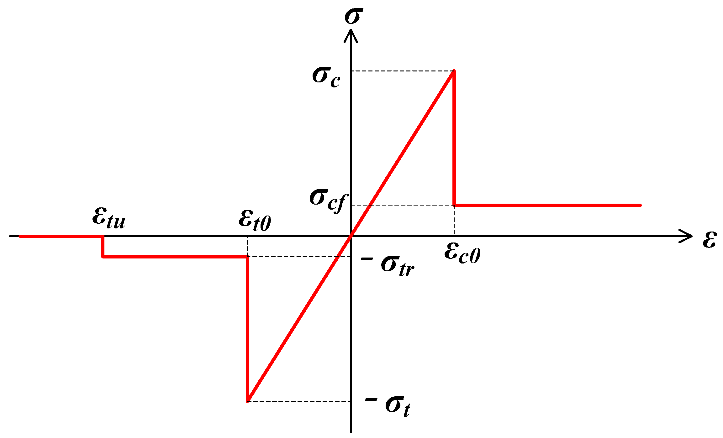
- The material is elastic-brittle, and the mechanical behavior of the material follows the elastic damage constitutive rule.
- (3)
- One element fails in tensile mode if the minimum principal stress is lower than the negative tensile strength, whereas an element fails in shear mode if the shear stress meets the Mohr–Coulomb strength criterion.
- (4)
- The main concern is the change in the mechanical phenomena of the material over the wetting time, and the complex chemical actions during the moisture diffusion of the material are neglected.
- (5)
- Dilation and softening induced by moisture diffusion in the material are similar to those induced by the thermal effects, although the physical mechanisms are different.
3. Determination of the Material Parameters
3.1. Homogeneity Index
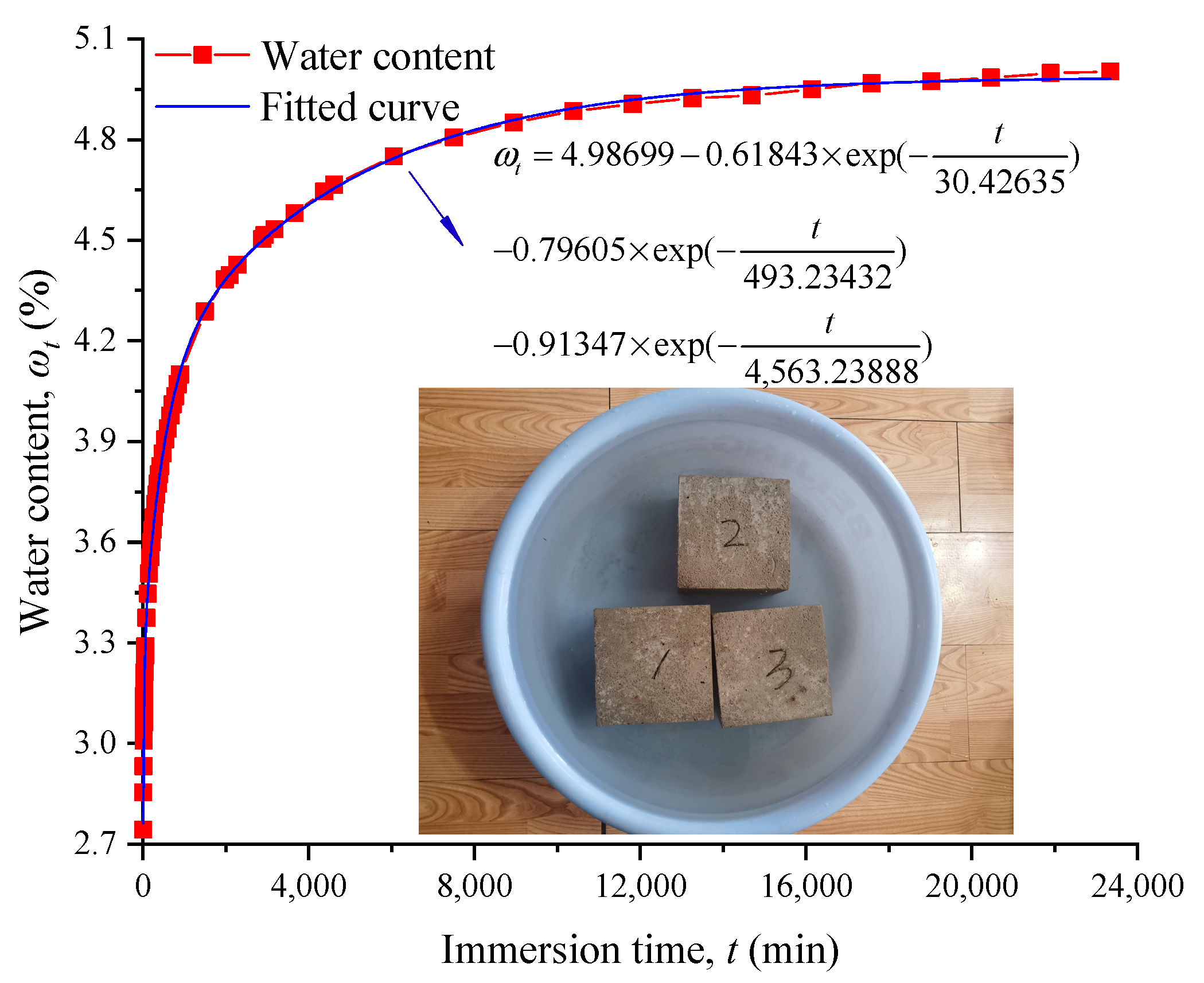
3.2. Water Content
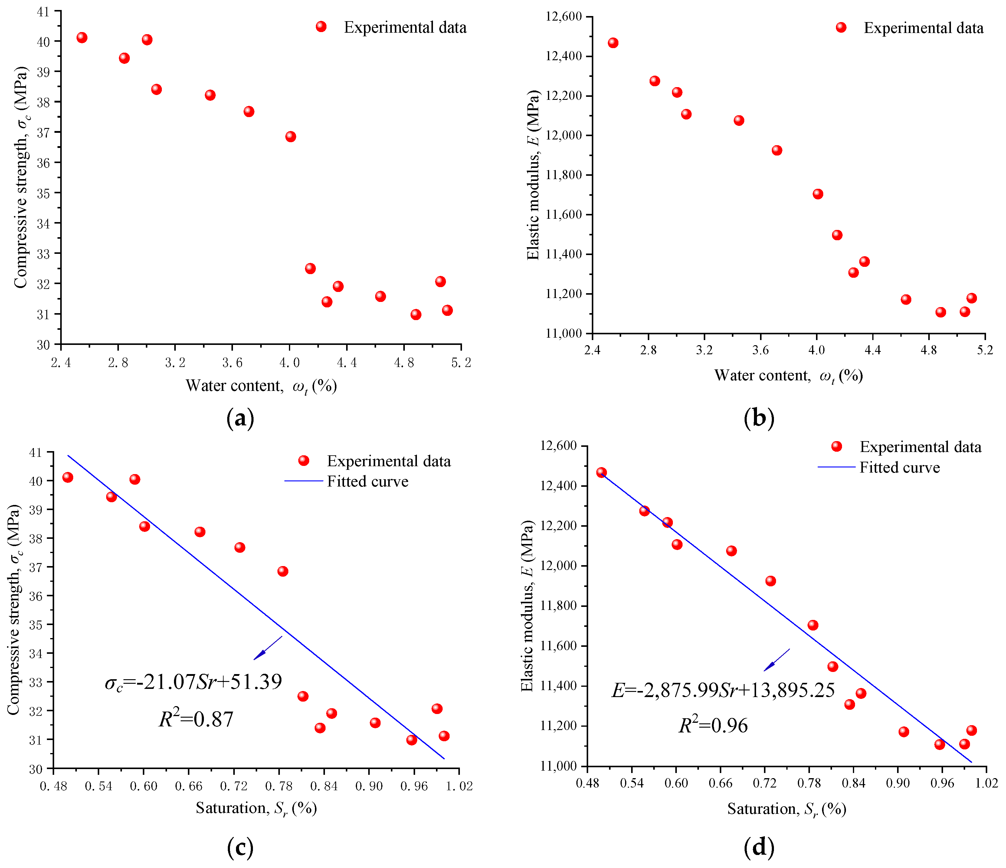
3.3. Degradation Coefficient for Mechanical Properties
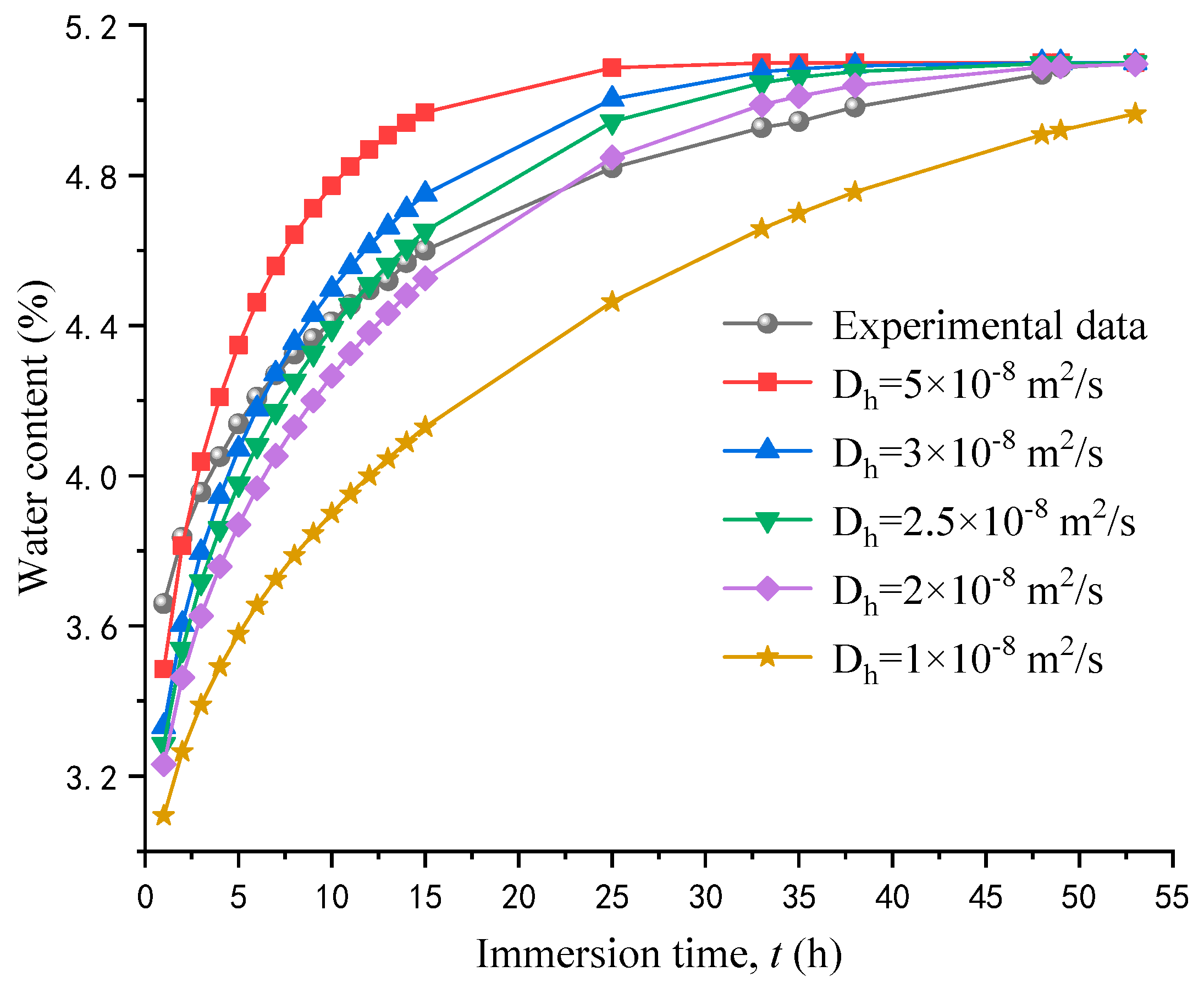
3.4. Humidity Diffusion Coefficient
4. Time-Dependent Deformation in a Water Environment
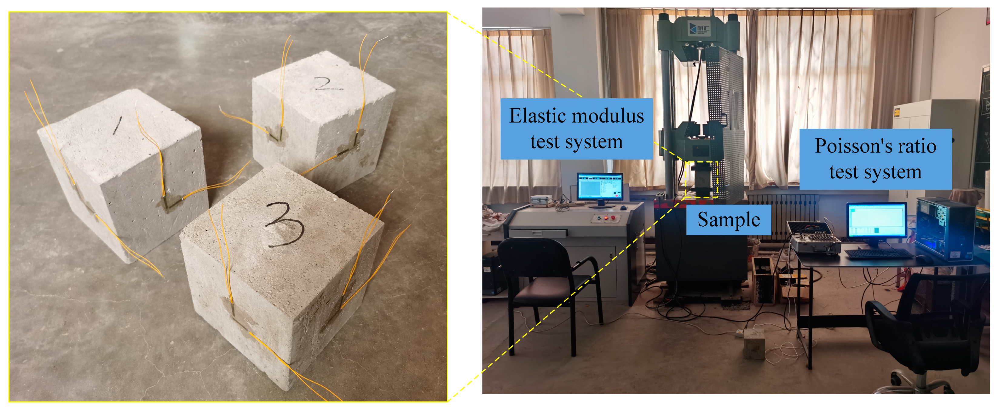
4.1. Test Process
4.2. The Evolution of Strain
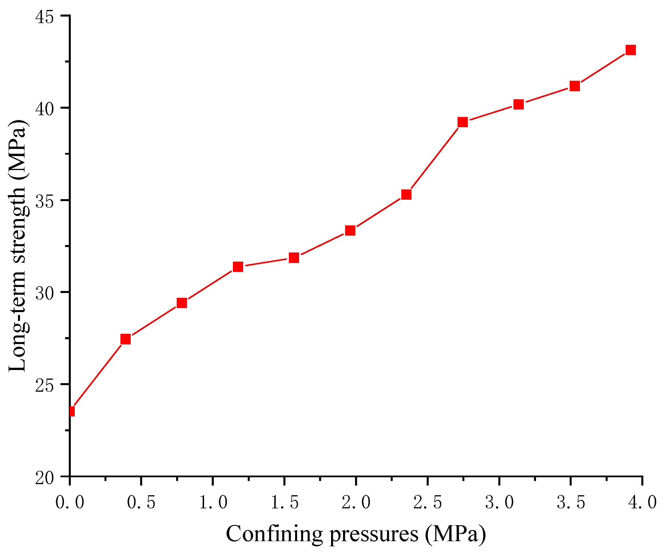
4.3. Long-Term Strength
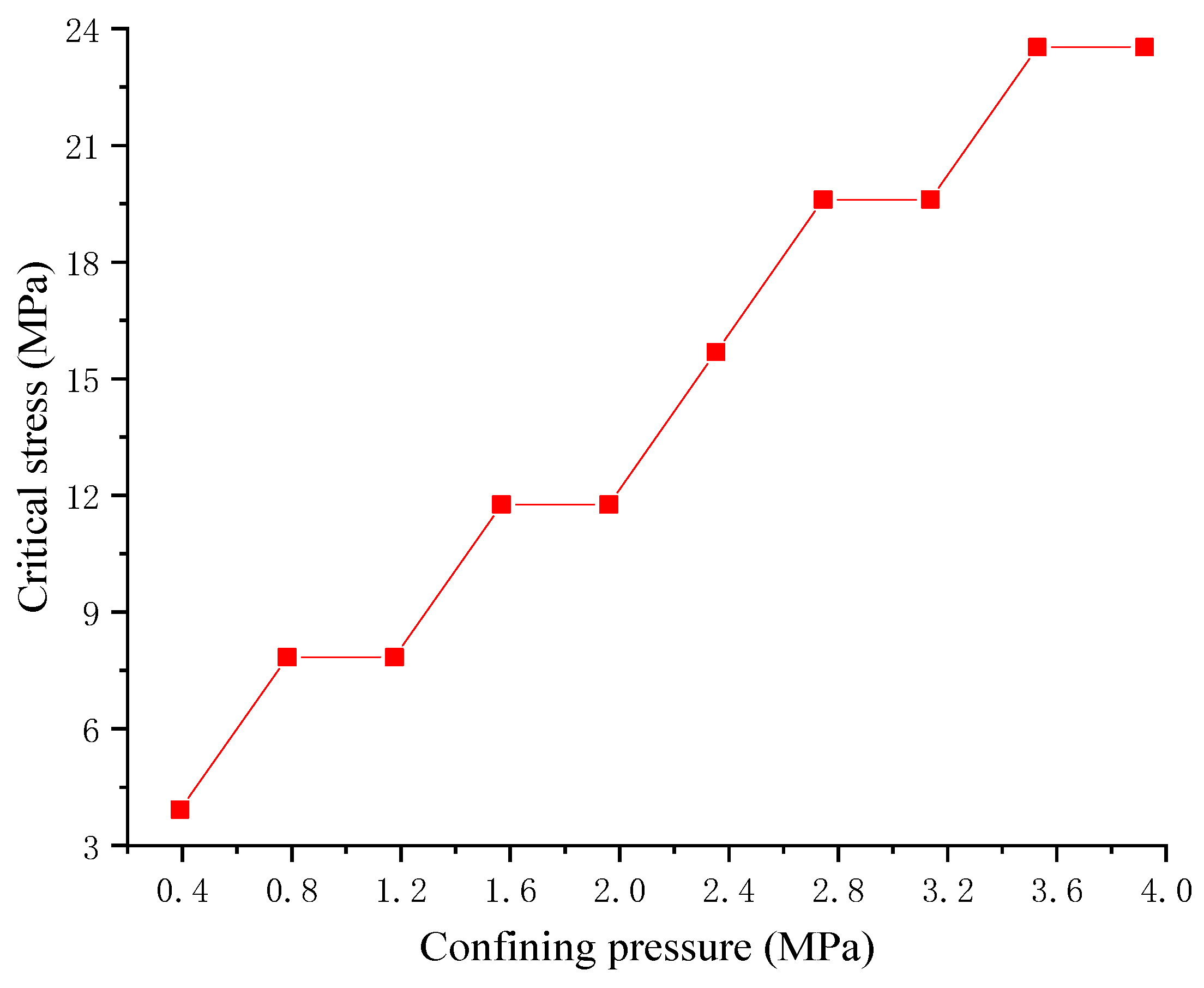
4.4. Critical Stress for Accelerated Creep
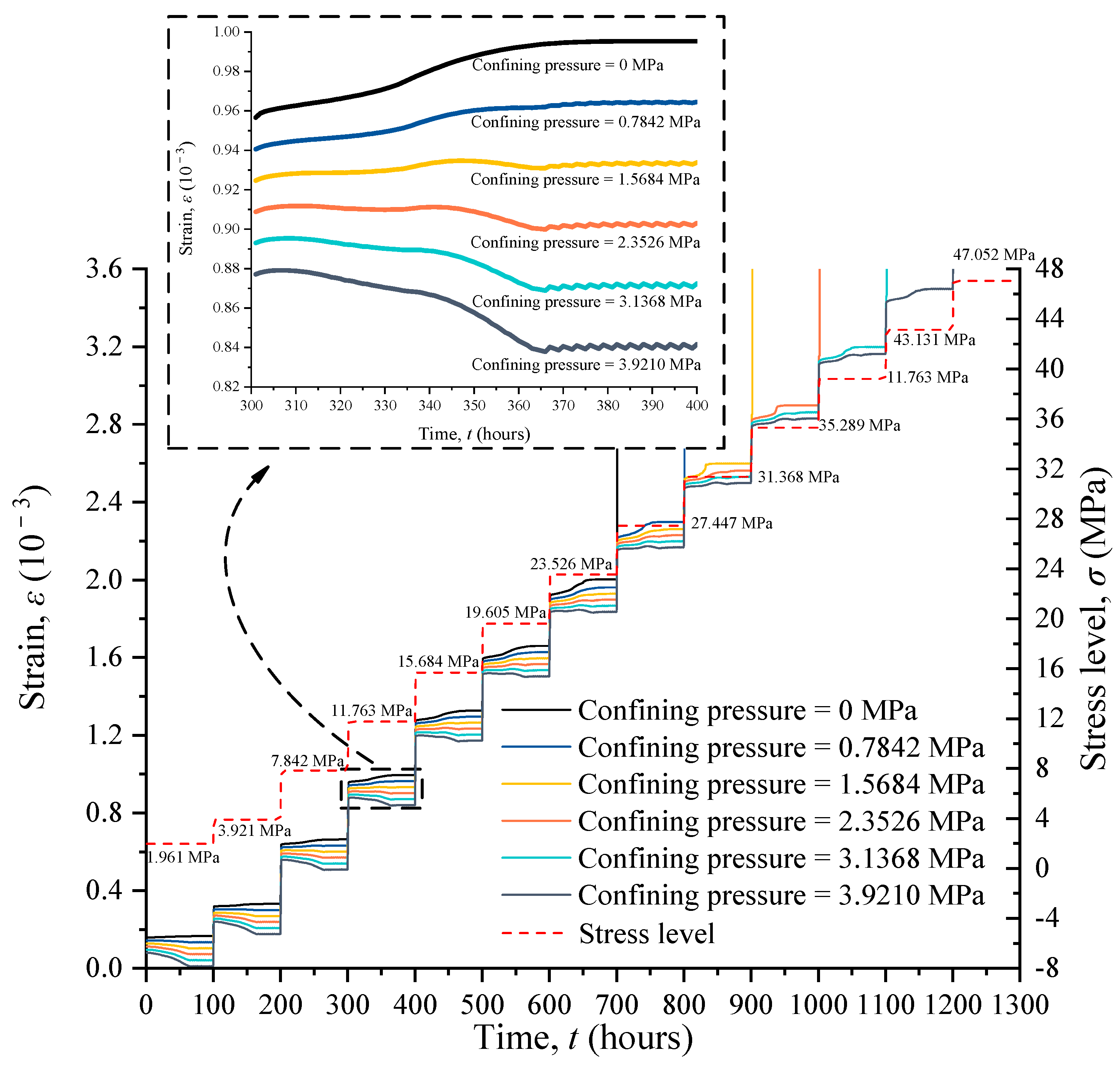
4.5. The Evolution of Strain under Confining Pressures
5. Discussion
6. Conclusions
- (1)
- The water absorption process can be divided into three distinct stages, i.e., the quick absorption stage, the slow absorption stage, and the stable absorption stage. Furthermore, the water content increased quickly in the first stage and lasted for around 15 h. Then, the rate of water absorption gradually decreased and eventually remained constant after immersion in water for 365 h. In addition, the average water content of the saturated sample was 4.88%.
- (2)
- The elastic modulus and compressive strength decrease as the water content increases. Moreover, when the water content exceeds 4.0%, the elastic modulus and compressive strength decrease significantly.
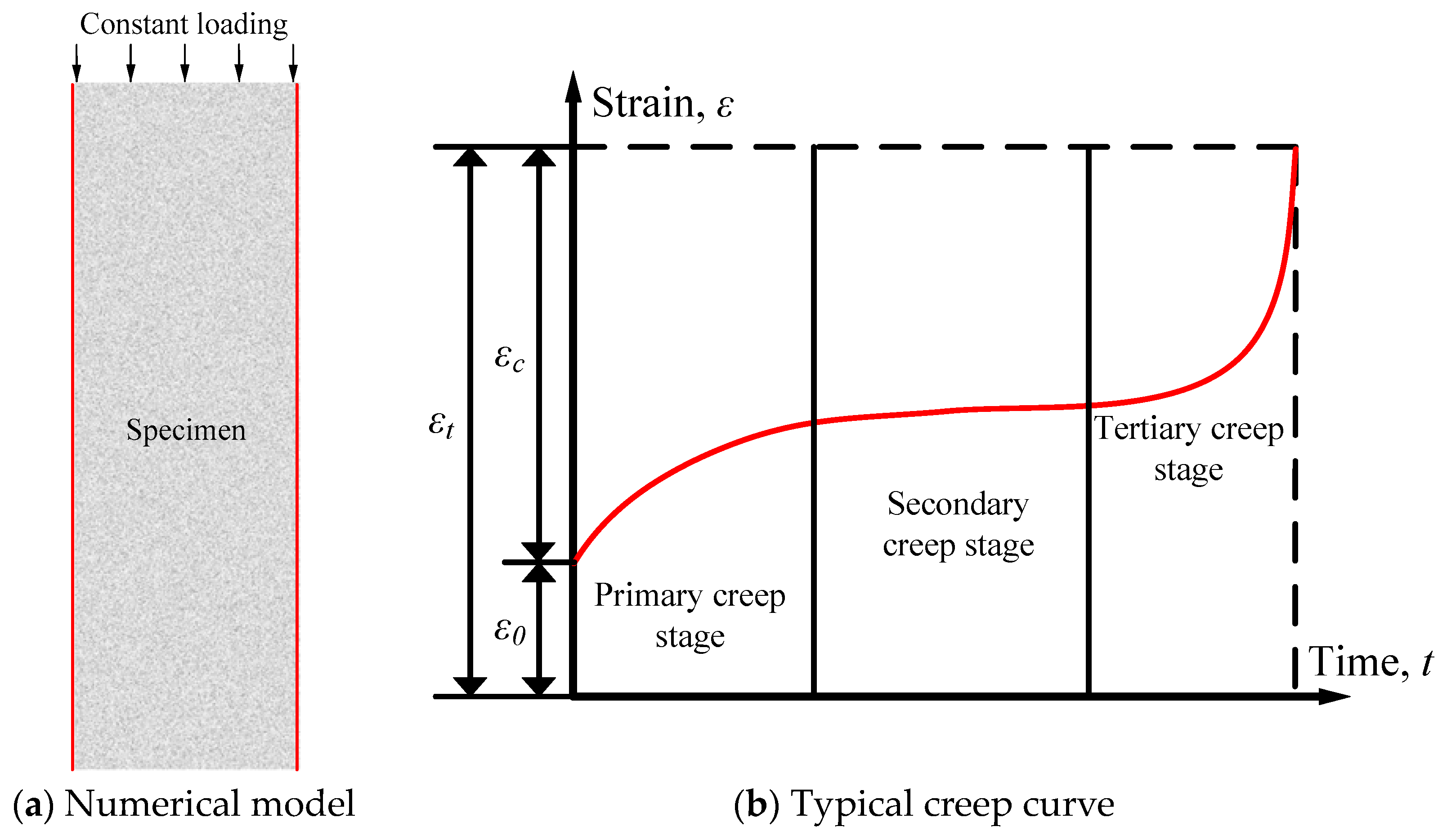
- (3)
- If the stress level is lower than 60% of the compressive strength of RAC, only the primary creep stage and the secondary creep stage exist, while the tertiary creep stage does not appear. In the primary creep stage, the strain first increases at a decreasing rate then increases with a steady rate, and finally increases with a decreasing rate. The strain–time curve is in the form of a saddle, and the saddle-shaped trend becomes more obvious as the stress level increases. Simultaneously, the strain variation law of the saddle-shaped trend is mainly affected by the evolution law of pores inside the specimen.
- (4)
- If the stress level is higher than 70% of the compressive strength of RAC, the strain increases abruptly with time and the secondary creep stage is not obvious. The model fails quickly if the stress level is higher than 70% of the compressive strength of RAC. The RAC selected in this paper has a long-term strength between 60% and 70% of its compressive strength. Based on the consideration of practical project safety applications, the RAC long-term strength in a water environment is selected as a lower limit with 60% of its compressive strength. In practical engineering, when the stress level is higher than the long-term strength value, the recycled concrete may appear to be in the tertiary creep stage, leading to the failure of the sample. This phenomenon should be paid attention to.
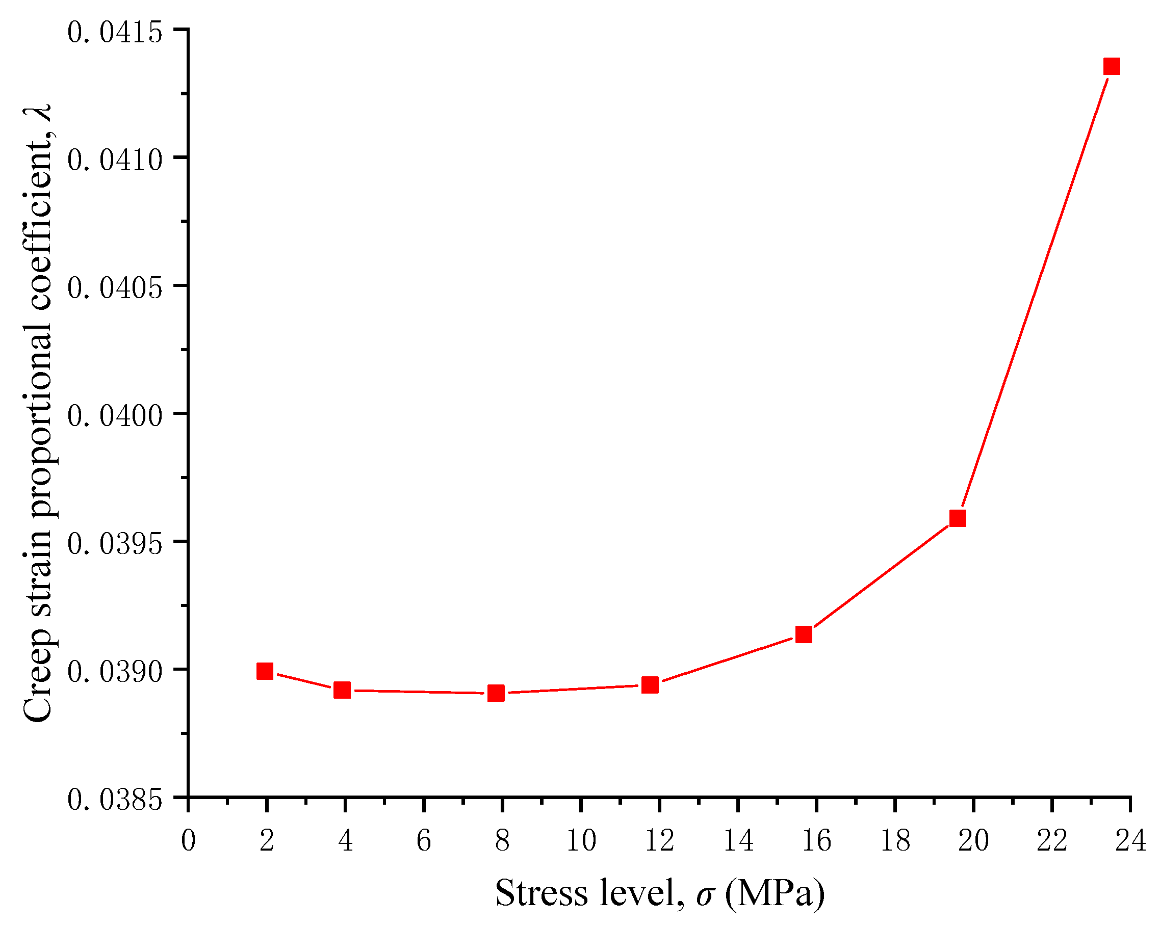
- (5)
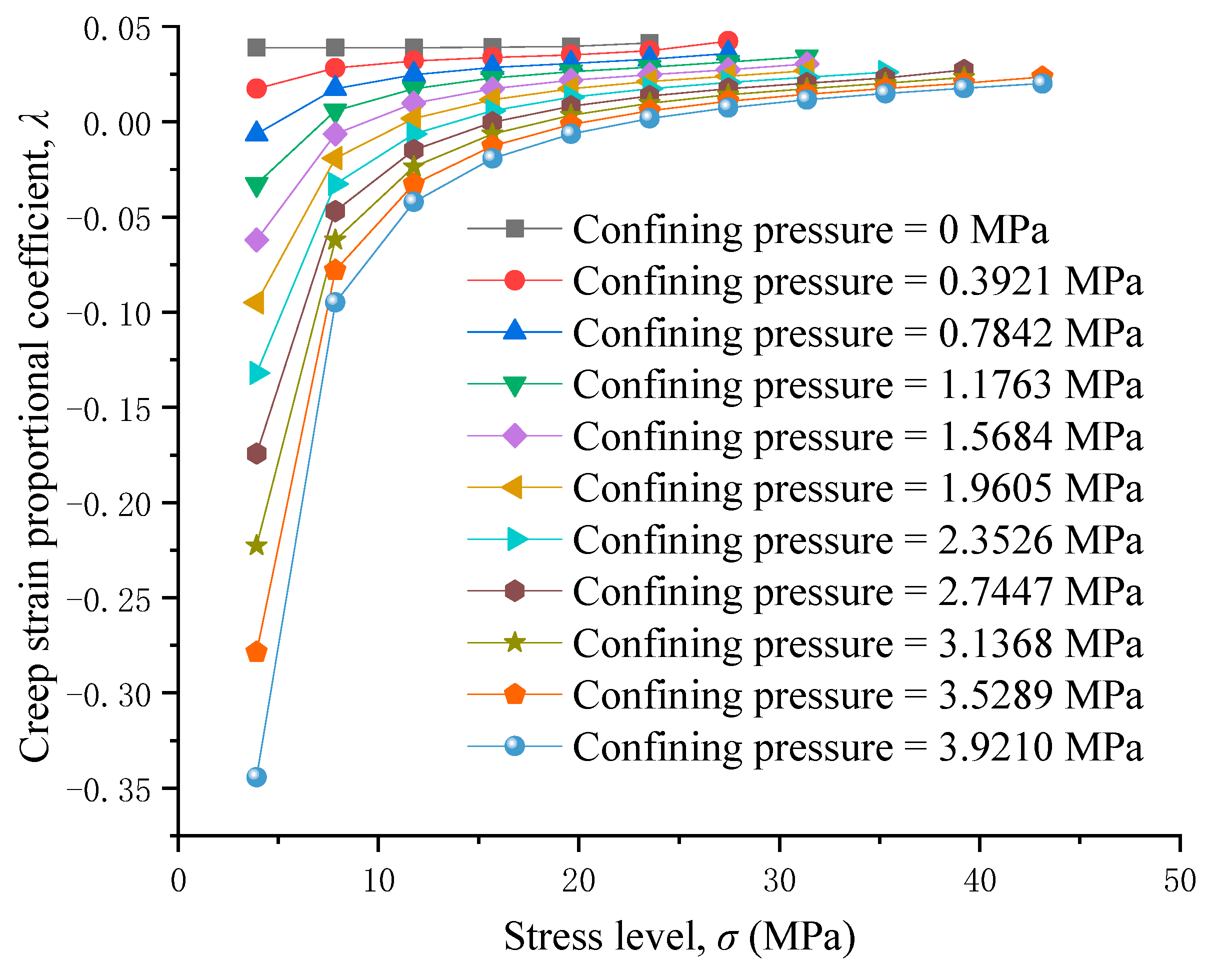
- In the absence of confining pressures, the creep strain proportional coefficient decreases first and then increases with the increases in stress level. If the stress level is higher than 20% of the compressive strength of RAC, the proportion of creep strain in the total strain increases, and the creep deformation becomes more and more obvious. Therefore, if the stress level is higher than 20% of the compressive strength of RAC, more attention should be paid to deformation monitoring in practical projects.
- (6)
- Confining pressures can effectively increase the long-term strength and critical stress of the RAC. Furthermore, confining pressures can reduce creep deformation of the RAC. In practical engineering, the long-term stable application of RAC in a water environment can be ensured by increasing the confining pressures.
Author Contributions
Funding
Institutional Review Board Statement
Informed Consent Statement
Data Availability Statement
Conflicts of Interest
References
- Singh, A.; Duan, Z.; Xiao, J.; Liu, Q. Incorporating recycled aggregates in self-compacting concrete: A review. J. Sustain. Cem.-Based Mater. 2019, 9, 165–189. [Google Scholar] [CrossRef]
- Yehia, S.; Helal, K.; Abusharkh, A.; Zaher, A.; Istaiyeh, H. Strength and durability evaluation of recycled aggregate concrete. Int. J. Concr. Struct. Mater. 2015, 9, 219–239. [Google Scholar] [CrossRef]
- Evangelista, L.; de Brito, J. Flexural behaviour of reinforced concrete beams made with fine recycled concrete aggregates. KSCE J. Civ. Eng. 2017, 21, 353–363. [Google Scholar] [CrossRef]
- Fan, C.; Huang, R.; Hwang, H.; Chao, S. Properties of concrete incorporating fine recycled aggregates from crushed concrete wastes. Constr. Build. Mater. 2016, 112, 708–715. [Google Scholar] [CrossRef]
- Adeyemi, A.; Sreekanta, D. Evaluation of the durability properties of engineered cementitious composites incorporating recycled concrete as aggregate. J. Mater. Civ. Eng. 2021, 33, 04020439. [Google Scholar]
- Ali, M.A.; Murat, T.; Kambiz, R. Mechanical and durability performance of concrete incorporating fine recycled concrete and glass aggregates. Mater. Struct. 2015, 48, 2629–2640. [Google Scholar]
- Kou, S.C.; Poon, C.S. Enhancing the durability properties of concrete prepared with coarse recycled aggregate. Constr. Build. Mater. 2012, 35, 69–76. [Google Scholar] [CrossRef]
- Singh, R.; Nayak, D.; Pandey, A.; Kumar, P.; Kumar, V. Effects of recycled fine aggregates on properties of concrete containing natural or recycled coarse aggregates: A comparative study. J. Build. Eng. 2021, 45, 103442. [Google Scholar] [CrossRef]
- Chao, Z.; Gong, B.; Yue, W.; Xu, X.; Shi, D.; Yang, C.; Hu, T. Experimental study on stress-dependent gas permeability and porosity of artificially cracked cement mortar. Constr. Build. Mater. 2022, 359, 129290. [Google Scholar] [CrossRef]
- Erhan, G.; Mehmet, G.; Qays, K.; Suleyman, I. Effect of different substitution of natural aggregate by recycled aggregate on performance characteristics of pervious concrete. Mater. Struct. 2016, 49, 521–536. [Google Scholar]
- Miguel, B.; de Brito, J.; Jorge, P.; Luis, E. Durability performance of concrete with recycled aggregates from construction and demolition waste plants. Constr. Build. Mater. 2015, 77, 357–369. [Google Scholar]
- Huang, J.; Zou, C.; Sun, D.; Yang, B.; Yan, J. Effect of recycled fine aggregates on alkali-activated slag concrete properties. Structures 2021, 30, 89–99. [Google Scholar] [CrossRef]
- Xiao, J.; Zhang, H.; de Brito, J. M&S highlight: Limbachiya, et al. (2000), Use of recycled aggregate in high-strength concrete. Mater. Struct. 2021, 55, 40. [Google Scholar]
- Tam, V.W.Y.; Tam, C.M. Assessment of durability of recycled aggregate concrete produced by two-stage mixing approach. J. Mater. Sci. 2007, 42, 3592–3602. [Google Scholar] [CrossRef]
- Soares, D.; de Brito, J.; Ferreira, J.; Pacheco, J. Use of coarse recycled aggregates from precast concrete rejects: Mechanical and durability performance. Constr. Build. Mater. 2014, 71, 263–272. [Google Scholar] [CrossRef]
- George, W.; Elhem, G. Shear strength of reinforced concrete beams with recycled aggregates. Adv. Struct. Eng. 2019, 22, 1938–1951. [Google Scholar]
- Yu, J.; Gong, B.; Cao, C.; Tang, C. A novel cohesive interlayer model considering friction. Int. J. Solids Struct. 2024, 305, 113049. [Google Scholar] [CrossRef]
- Arezoumandi, M.; Smith, A.; Volz, J.S.; Khayat, K.H. An experimental study on flexural strength of reinforced concrete beams with 100% recycled concrete aggregate. Eng. Struct. 2015, 88, 154–162. [Google Scholar] [CrossRef]
- Domingo, A.; Lazaro, C.; Gayarre, F.L.; Serrano, M.A.; Lopoz-Colina, C. Long term deformations by creep and shrinkage in recycled aggregate concrete. Mater. Struct. 2010, 43, 1147–1160. [Google Scholar] [CrossRef]
- Knaack, A.M.; Kurama, Y.C. Sustained service load behavior of concrete beams with recycled concrete aggregates. Aci Struct. J. 2015, 112, 565–577. [Google Scholar] [CrossRef]
- Seo, T.S.; Lee, M.S. Experimental Study on Tensile Creep of Coarse Recycled Aggregate Concrete. Int. J. Concr. Struct. Mater. 2015, 9, 337–343. [Google Scholar] [CrossRef]
- Liu, C.; Lv, Z.; Zhu, C.; Bai, G.; Zhang, Y. Study on Calculation Method of Long Term Deformation of RAC Beam based on Creep Adjustment Coefficient. KSCE J. Civ. Eng. 2019, 23, 260–267. [Google Scholar] [CrossRef]
- Sryh, L.; Forth, J. Long-term flexural behaviour of cracked reinforced concrete beams with recycled aggregate. Int. J. Concr. Struct. Mater. 2022, 16, 19. [Google Scholar] [CrossRef]
- Liu, X.; Yu, W.; Huang, Y.; Yang, G.; You, W.; Gao, L.; Song, J. Long-term behaviour of recycled aggregate concrete beams prestressed with carbon fibre-reinforced polymer (CFRP) tendons. Case Stud. Constr. Mater. 2023, 18, e01785. [Google Scholar] [CrossRef]
- Knaack, A.M.; Kurama, Y.C. Effect of recycled concrete coarse aggregates on service-load deflections of reinforced concrete columns. Eng. Struct. 2020, 204, 109955. [Google Scholar] [CrossRef]
- Geng, Y.; Wang, Y.; Chen, J. Time-dependent behaviour of steel tubular columns filled with recycled coarse aggregate concrete. J. Constr. Steel Res. 2016, 122, 455–468. [Google Scholar] [CrossRef]
- Tošić, N.; Kurama, Y. Parametric numerical study on service-load deflections of reinforced recycled aggregate concrete slabs and beams based on fib Model Code 2010. Struct. Concr. 2020, 21, 2854–2868. [Google Scholar] [CrossRef]
- Guo, M.; Grondin, F.; Loukili, A. Numerical method to model the creep of recycled aggregate concrete by considering the old attached mortar. Cem. Concr. Res. 2019, 118, 14–24. [Google Scholar] [CrossRef]
- Matteo, O.C.; Riccardo, C.; di Prisco, C. Experimental Study on the Water-Induced Weakening of Calcarenites. Rock Mech. Rock Eng. 2015, 48, 441–461. [Google Scholar]
- Zhao, Z.H.; Song, E.X. Particle mechanics modeling of creep behavior of rockfill materials under dry and wet conditions. Comput. Geotech. 2015, 68, 137–146. [Google Scholar] [CrossRef]
- Li, Z.; Yang, J.; Liu, L.; Yan, S. Evaluating the creep characteristics of recycled construction waste materials under saturated and dry condition. Arab. J. Geosci. 2021, 14, 153. [Google Scholar] [CrossRef]
- Wang, Y.; Gong, B.; Tang, C.; Yang, X. Size effect and lateral pressure effect on the mechanical resistance of columnar jointed basalt. Int. J. Rock Mech. Min. Sci. 2023, 171, 105571. [Google Scholar] [CrossRef]
- Gao, M.; Gong, B.; Liang, Z.; Jia, S.; Zou, J. Investigation of the anisotropic mechanical response of layered shales. Energy Sci. Eng. 2023, 11, 4737–4754. [Google Scholar] [CrossRef]
- Chen, T.; Gong, B.; Tang, C. Origin and Evolution of Cracks in the Glaze Surface of a Ceramic during the Cooling Process. Materials 2023, 16, 5508. [Google Scholar] [CrossRef] [PubMed]
- Feng, X.; Gong, B.; Cheng, X.; Zhang, H.; Tang, C. Anisotropy and microcrack-induced failure precursor of shales under dynamic splitting. Geomat. Nat. Hazards Risk 2022, 13, 2864–2889. [Google Scholar] [CrossRef]
- Gong, B.; Liang, Z.; Liu, X. Nonlinear deformation and failure characteristics of horseshoe-shaped tunnel under varying principal stress direction. Arab. J. Geosci. 2022, 15, 475. [Google Scholar] [CrossRef]
- Yu, C.; Gong, B.; Wu, N.; Xu, P.; Bao, X. Simulation of the Fracturing Process of Inclusions Embedded in Rock Matrix under Compression. Appl. Sci. 2022, 12, 8041. [Google Scholar] [CrossRef]
- Liu, X.; Gong, B.; Song, K.; Liu, H. Indirect tensile strength test on heterogeneous rock using square plate sample with a circular hole. Lithosphere 2024, 2024, lithosphere_2023_322. [Google Scholar] [CrossRef]
- Gong, B.; Zhao, T.; Thusyanthan, I.; Tang, C. Modelling rock fracturing by a novel implicit continuous to discontinuous method. Comput. Geotech. 2024, 166, 106035. [Google Scholar] [CrossRef]
- Weibull, W. A statistical distribution function of wide applicability. J. Appl. Mech. 1951, 18, 293–297. [Google Scholar] [CrossRef]
- Li, L.; Guan, J.; Yuan, P.; Yin, Y.; Li, Y. A Weibull distribution-based method for the analysis of concrete fracture. Eng. Fract. Mech. 2021, 256, 107964. [Google Scholar] [CrossRef]
- Bažant, Z.P.; Najjar, L.J. Drying of concrete as a nonlinear diffusion problem. Cem. Concr. Res. 1971, 1, 461–473. [Google Scholar] [CrossRef]
- Bažant, Z.P.; Najjar, L.J. Nonlinear water diffusion in nonsaturated concrete. Matériaux Constr. 1972, 5, 3–20. [Google Scholar] [CrossRef]
- Miao, X.; Lu, A.; Mao, X.; Zhang, D. Numerical simulation for roadways in swelling rock under coupling function of water and ground pressure. J. China Univ. Min. Technol. 2002, 12, 120–125. [Google Scholar]
- Tang, S.; Yu, C.; Tang, C. Numerical modeling of the time-dependent development of the damage zone around a tunnel under high humidity conditions. Tunn. Undergr. Space Technol. 2018, 76, 48–63. [Google Scholar] [CrossRef]
- Tang, S.; Tang, C. Numerical studies on tunnel floor heave in swelling ground under humid conditions. Int. J. Rock Mech. Min. Sci. 2012, 55, 139–150. [Google Scholar] [CrossRef]
- GB 50010-2010; The Chinese Code for Design of Concrete Structures. Chinese Standard: Beijing, China, 2011.
- Xu, H.C.; Zhang, Y.; Zhao, C.; Miao, C.; Sun, X. Creep structure effect of layered rock mass based on acoustic emission characteristics. Shock Vib. 2021, 2021, 7419741. [Google Scholar] [CrossRef]
- Branko, D.; Charles, F. Evidence for a Long-Term Strength Threshold in Crystalline Rock. Rock Mech. Rock Eng. 2010, 43, 513–531. [Google Scholar]
- Yu, C.; Tang, S.; Tang, C.; Duan, D.; Zhang, Y.; Liang, Z.; Ma, K.; Ma, T. The effect of water on the creep behavior of red sandstone. Eng. Geol. 2019, 253, 64–74. [Google Scholar] [CrossRef]
- Lye, C.Q.; Dhir, R.K.; Ghataora, G.S.; Li, H. Creep strain of recycled aggregate concrete. Constr. Build. Mater. 2016, 102, 244–259. [Google Scholar] [CrossRef]
- Zhu, Y.G.; Kou, S.C.; Poon, C.S.; Dai, J.G.; Li, Q.Y. Influence of silane-based water repellent on the durability properties of recycled aggregate concrete. Cem. Concr. Compos. 2013, 35, 32–38. [Google Scholar] [CrossRef]
- Medina, C.; Sánchez de Rojas, M.I.; Frías, M. Properties of recycled ceramic aggregate concretes: Water resistance. Cem. Concr. Compos. 2013, 40, 21–29. [Google Scholar] [CrossRef]
- Ge, P.; Huang, W.; Zhang, H.; Quan, W.; Guo, Y. Study on Calculation Model for Compressive Strength of Water Saturated Recycled Aggregate Concrete. KSCE J. Civ. Eng. 2022, 26, 273–285. [Google Scholar] [CrossRef]
- Zhao, Y.; Zeng, W.; Zhang, H. Properties of recycled aggregate concrete with different water control methods. Constr. Build. Mater. 2017, 152, 539–546. [Google Scholar] [CrossRef]
- Delobel, F.; Bulteel, D.; Mechling, J.M.; Lecomte, A.; Cyr, M.; Rémond, S. Application of ASR tests to recycled concrete aggregates: Influence of water absorption. Constr. Build. Mater. 2016, 124, 714–721. [Google Scholar] [CrossRef]
- Koenders, E.A.B.; Pepe, M.; Martinelli, E. Compressive strength and hydration processes of concrete with recycled aggregates. Cem. Concr. Res. 2014, 56, 203–212. [Google Scholar] [CrossRef]


| Material Usage (kg) | ||||||
|---|---|---|---|---|---|---|
| Water | Cement | Recycled Fine Aggregate | Natural Coarse Aggregate | Mineral Powder | Flyash | Polycarboxylate Superplasticizer |
| 175 | 240 | 895 | 940 | 60 | 60 | 5.8 |
| Sample Number | Elastic Modulus (MPa) | Compressive Strength (MPa) | Poisson’s Ratio |
|---|---|---|---|
| 1 | 12,378.8 | 38.85 | 0.24 |
| 2 | 11,949.3 | 40.04 | 0.25 |
| 3 | 12,606.1 | 38.74 | 0.27 |
| Mean | 12,311.4 | 39.21 | 0.25 |
| Homogeneity Index | Elastic Modulus (MPa) | Compressive Strength (MPa) |
|---|---|---|
| 1 | 12,088 | 291.00 |
| 2 | 13,025 | 50.10 |
| 3 | 12,998 | 42.60 |
| 4 | 12,868 | 40.79 |
| 5 | 12,705 | 39.94 |
| 6 | 12,540 | 39.45 |
| 7 | 12,383 | 39.16 |
| 8 | 12,239 | 38.90 |
| Parameter Name | Value |
|---|---|
| Homogeneity index | 7 |
| Elastic modulus (MPa) | 12,311.4 |
| Poisson’s ratio | 0.25 |
| Compressive strength (MPa) | 39.21 |
| Critical saturation | 82% |
| Initial saturation | 55% |
| Degradation coefficient of compressive strength | 0.09 |
| Degradation coefficient of elastic modulus | 0.04 |
| Stress Level (MPa) | Initial Strain (10−3) | Creep Strain (10−3) | Total Strain (10−3) |
|---|---|---|---|
| 1.9605 | 0.1594 | 0.0065 | 0.1659 |
| 3.921 | 0.3188 | 0.0129 | 0.3317 |
| 7.842 | 0.6379 | 0.0258 | 0.6637 |
| 11.763 | 0.9566 | 0.0388 | 0.9954 |
| 15.684 | 1.2745 | 0.0519 | 1.3263 |
| 19.605 | 1.5936 | 0.0657 | 1.6593 |
| 23.526 | 1.9199 | 0.0828 | 2.0027 |
Disclaimer/Publisher’s Note: The statements, opinions and data contained in all publications are solely those of the individual author(s) and contributor(s) and not of MDPI and/or the editor(s). MDPI and/or the editor(s) disclaim responsibility for any injury to people or property resulting from any ideas, methods, instructions or products referred to in the content. |
© 2024 by the authors. Licensee MDPI, Basel, Switzerland. This article is an open access article distributed under the terms and conditions of the Creative Commons Attribution (CC BY) license (https://creativecommons.org/licenses/by/4.0/).
Share and Cite
Liu, X.; Gong, B.; Fu, Y.; Jiang, G.; Wang, J. Investigation of the Time-Dependent Deformation of Recycled Aggregate Concrete in a Water Environment. Materials 2024, 17, 4588. https://doi.org/10.3390/ma17184588
Liu X, Gong B, Fu Y, Jiang G, Wang J. Investigation of the Time-Dependent Deformation of Recycled Aggregate Concrete in a Water Environment. Materials. 2024; 17(18):4588. https://doi.org/10.3390/ma17184588
Chicago/Turabian StyleLiu, Xingzong, Bin Gong, Yufang Fu, Guanghui Jiang, and Jintao Wang. 2024. "Investigation of the Time-Dependent Deformation of Recycled Aggregate Concrete in a Water Environment" Materials 17, no. 18: 4588. https://doi.org/10.3390/ma17184588