
Modulating Carbon Fiber Surfaces with Vinyltriethoxysilane Grafting to Enhance Interface Properties of Carbon Fiber/Norbornene–Polyimide Composites

Abstract
1. Introduction
2. Experiment and Preparation
2.1. Materials
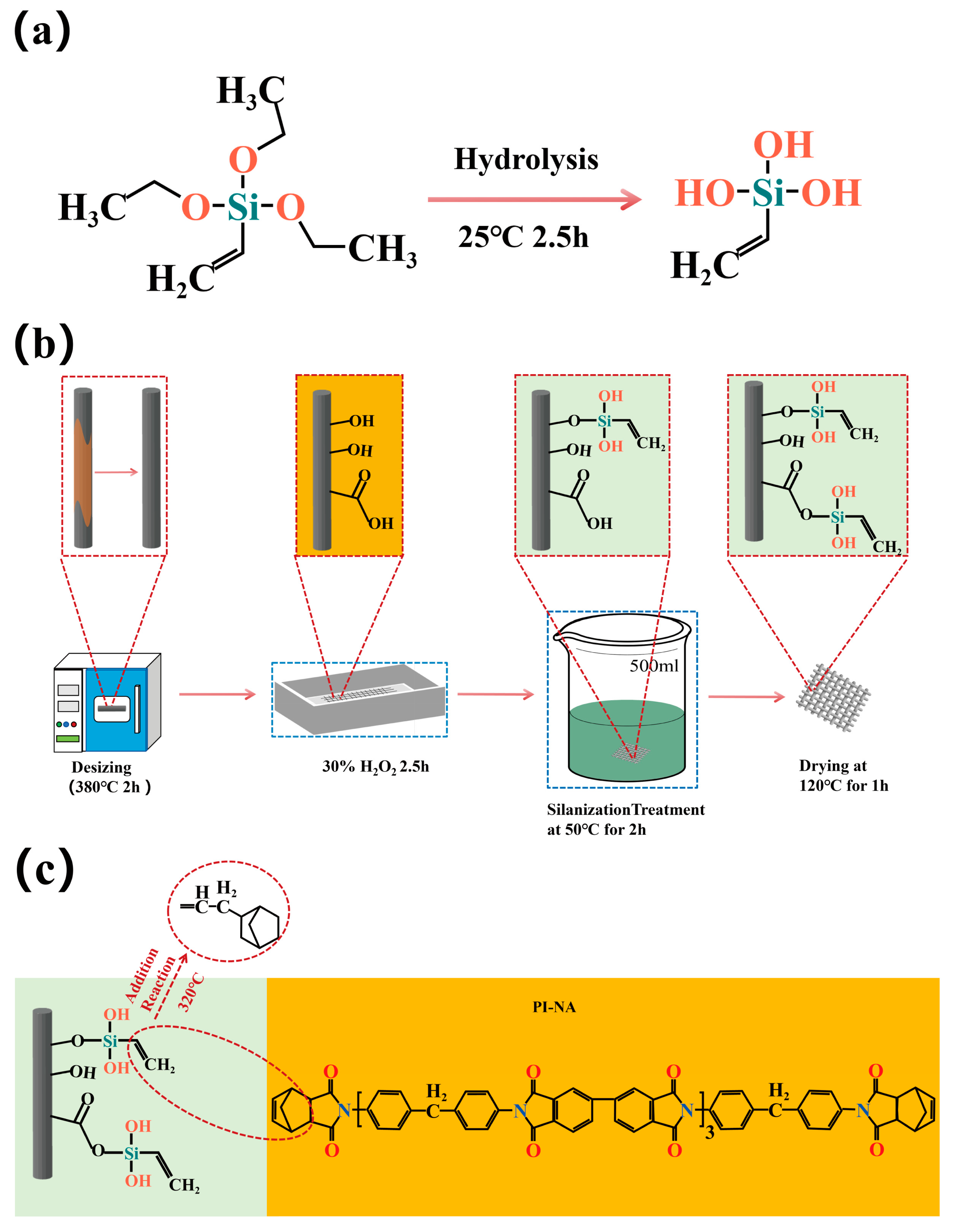
2.1.1. Desizing of Carbon Fiber
2.1.2. Preparation of TEVS Polymer Film
2.1.3. Surface Modification of Carbon Fiber by TEVS
2.1.4. Carbon Fiber/PI-NA Composite Preparation
3. Experimental Characterization
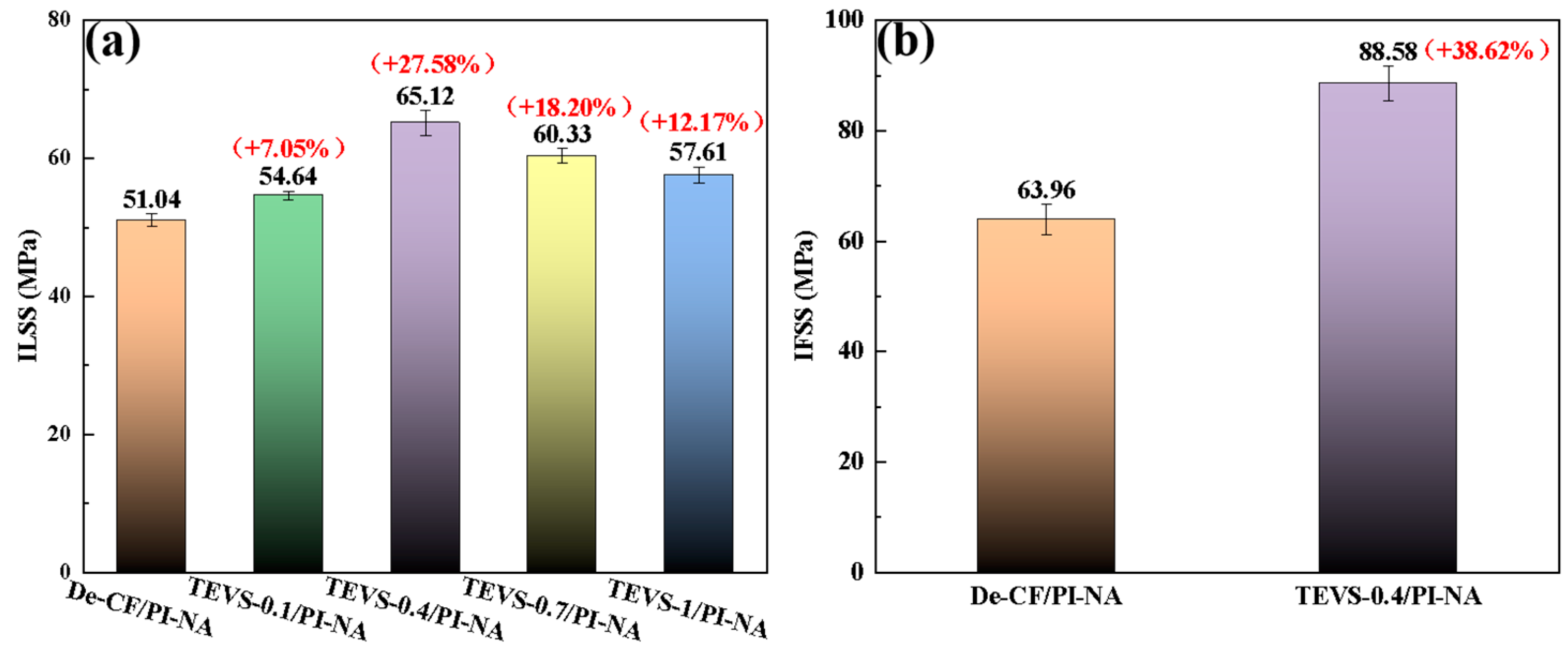
3.1. ILSS
3.2. IFSS
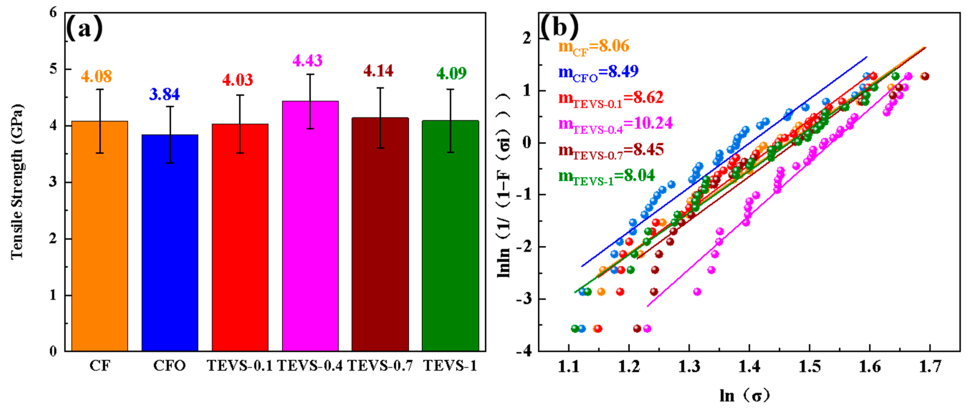
3.3. Single-Fiber Tensile Testing
3.4. FTIR of TEVS Polymer Film
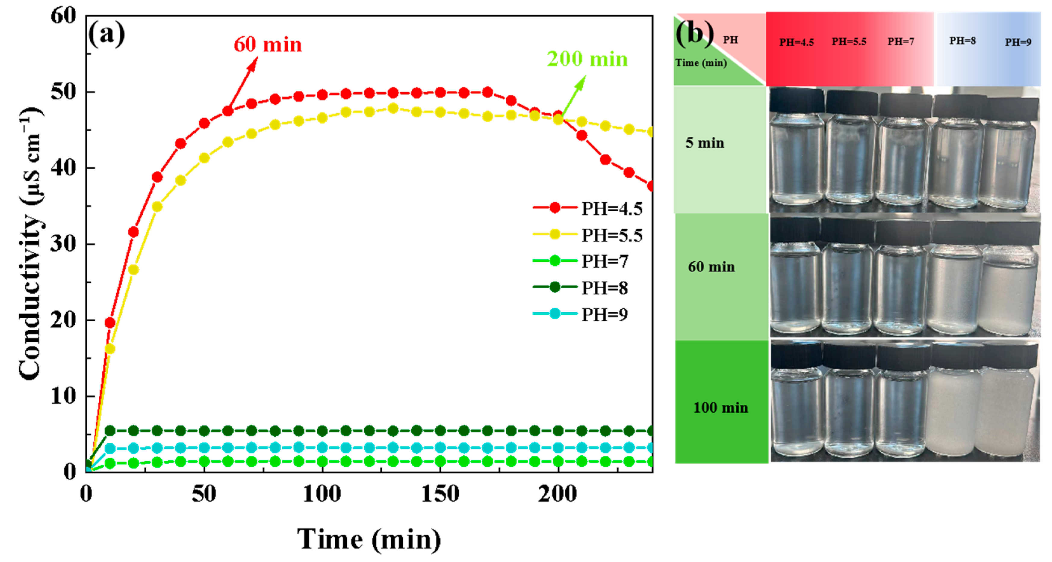
3.5. Hydrolytic Conductivity of Hydrolysis Solutions of TEVS
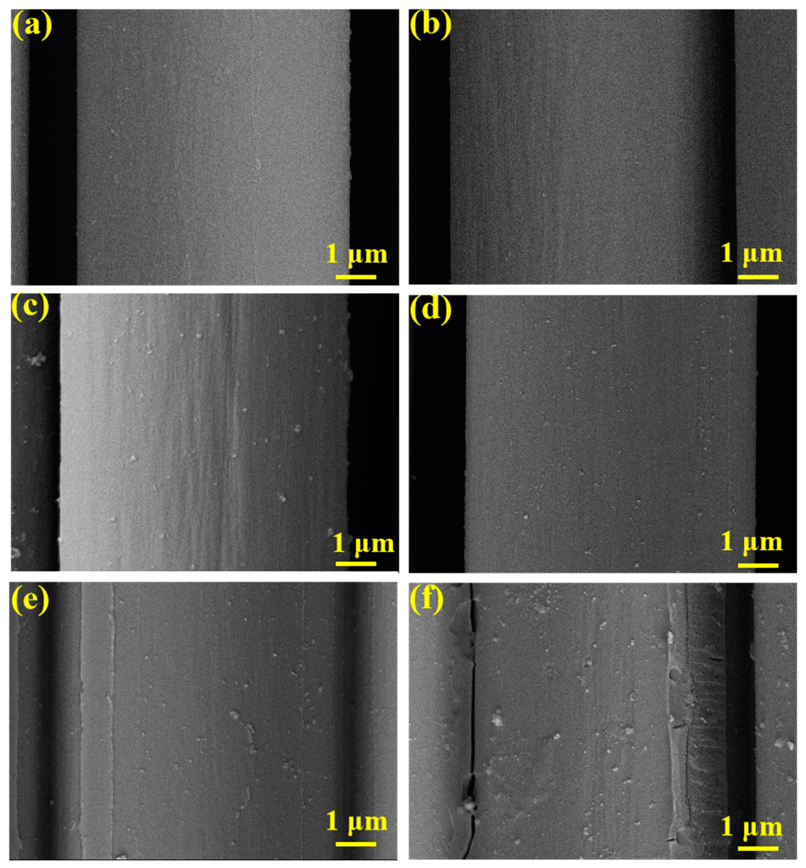
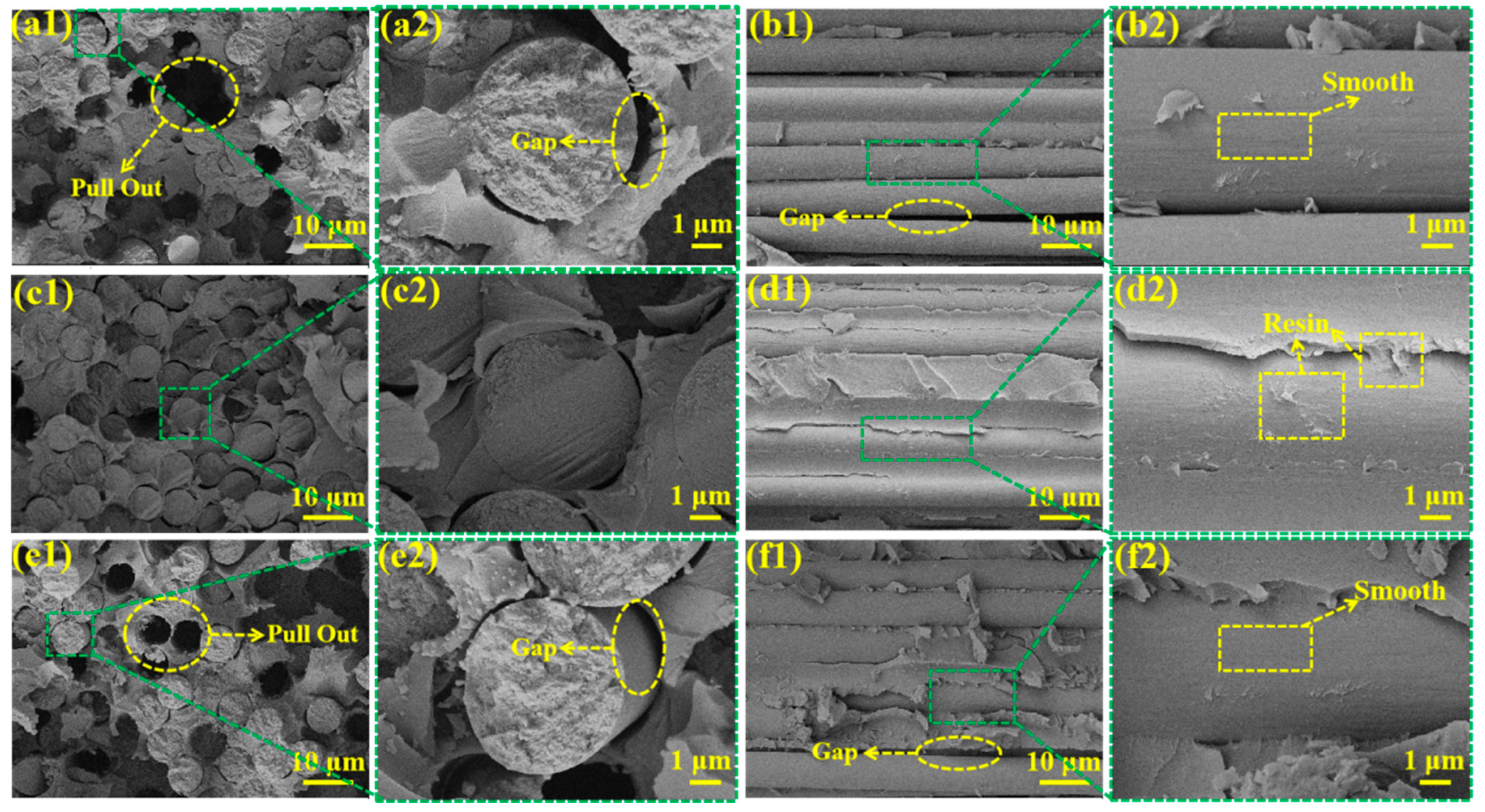
3.6. SEM Testing
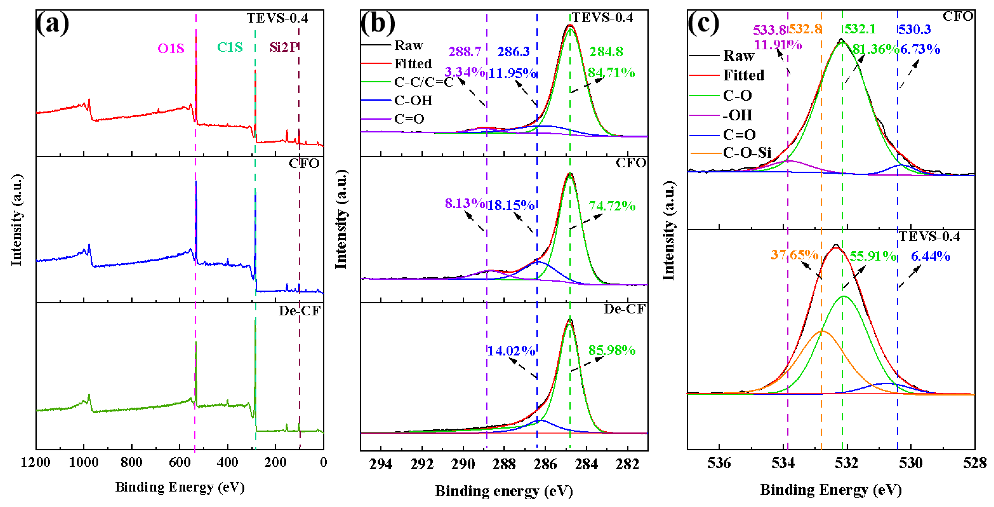
3.7. XPS Testing
3.8. Water Contact Angle
4. Results
5. Conclusions
Supplementary Materials
Author Contributions
Funding
Institutional Review Board Statement
Informed Consent Statement
Data Availability Statement
Conflicts of Interest
References
- Monti, M.; Palenzona, M.; Fiorino, F.; Baudach, F.; Onnis, A.; Romeo, A. Design, manufacturing and FEA prediction of the mechanical behavior of a hybrid-molded polycarbonate/continuous carbon fiber reinforced composite component. Compos. Pt. B-Eng. 2022, 238, 109891. [Google Scholar] [CrossRef]
- Fox, B. Making stronger carbon-fiber precursors. Science 2019, 366, 1314–1315. [Google Scholar] [CrossRef] [PubMed]
- Nunna, S.; Maghe, M.; Rana, R.; Varley, R.J.; Knorr, D.B.; Sands, J.M.; Creighton, C.; Henderson, L.C.; Naebe, M. Time dependent structure and property evolution in fibres during continuous carbon fiber manufacturing. Materials 2019, 12, 1069. [Google Scholar] [CrossRef] [PubMed]
- Zou, B.Y.; Qiu, L.H.; Lei, H.Y.; Liu, J.M.; Peng, W.F.; Zhao, H.Q.; Bao, F.; Huang, M.J. Fluorinated colorless polyimides with high heat-resistance and low birefringence. Chin. J. Polym. Sci. 2023, 41, 1599–1608. [Google Scholar] [CrossRef]
- Jiang, S.J.; Bi, Z.J.; Wang, J.K.; Zhao, J.X.; Fan, L.F.; Tian, L.Y.; Wu, Y.C.; Yi, N.B.; Wei, Z.Z.; Gan, F. Construction of novel Cu-a-diimide interactions for enhancing thermal resistance and dimensional stability of polyimide films. J. Mater. Res. Technol. 2023, 25, 1920–1930. [Google Scholar] [CrossRef]
- Dong, H.; Dong, J.; Li, X.T.; Zhao, X.; Xu, Q.S.; Zhang, J.L.; Zhang, Q.H. Preparation of High-Temperature Resistant Polyimide Fibers by Introducing the p-Phenylenediamine into Kapton-Type Polyimide. ACS Appl. Polym. Mater. 2024, 6, 2371–2380. [Google Scholar] [CrossRef]
- Yang, J.; Xiao, Q.F.; Lin, Z.; Li, Y.; Jia, X.H.; Song, H.J. Growth of ultra-dense MoS2 nanosheets on carbon fibers to improve the mechanical and tribological properties of polyimide composites. Friction 2021, 9, 1150–1162. [Google Scholar] [CrossRef]
- Wu, D.L.; Song, S.Y.; Han, Y.Q.; Ma, Q.H.; Liu, L.; Zhang, R.L.; Wang, M.J. Design of carbon fiber with nano accuracy for enrichment interface. Compos. Sci. Technol. 2022, 230, 109734. [Google Scholar] [CrossRef]
- Hu, W.L.; Sun, Z.J.; Yang, L.L.; Hu, C.J.; Zhang, S.Z.; Wang, F.X.; Yang, B.; Cang, Y. Interfacial strengthening and self-monitoring in carbon fiber-reinforced composites via carbon nanotube-based damage sensors. Nanomaterials 2022, 12, 3717. [Google Scholar] [CrossRef]
- Wang, F.; Li, J.; Yu, J.L.; Sun, S.F.; Li, X.Y.; Xie, F.; Jiang, B.; Wu, G.S.; Yu, F.; Huang, Y.D. Grafting of size-controlled graphene oxide sheets onto carbon fiber for reinforcement of carbon fiber/epoxy composite interfacial strength. Compos. Pt. A-Appl. Sci. Manuf. 2017, 101, 511–520. [Google Scholar] [CrossRef]
- Zhang, H.; Zhang, H.R.; Zhang, X.Q.; Sun, T.; Liang, M.; Chen, Y.; Heng, Z.G.; Zou, H.W. In-situ self-assembled block copolymer nanowires on high-modulus carbon fibers surface for enhanced interfacial performance of CFRPs. Chem. Eng. J. 2023, 451, 138583. [Google Scholar] [CrossRef]
- Liang, Y.C.; Zhang, X.H.; Wei, X.H.; Jing, D.Q.; Su, W.G.; Zhang, S.C. Contribution of surface roughness and oxygen-containing groups to the interfacial shear strength of carbon fiber/epoxy resin composites. Carbon 2024, 218, 1118683. [Google Scholar] [CrossRef]
- Li, S.L.; Zhang, C.Q.; Fu, J.F.; Zhou, Y.S.; Sun, J.Q.; He, Y.; Nan, F. Interfacial modification of carbon fiber by carbon nanotube gas-phase dispersion. Compos. Sci. Technol. 2020, 195, 108196. [Google Scholar] [CrossRef]
- Kim, D.K.; An, K.H.; Bang, Y.H.; Kwac, L.K.; Oh, S.Y.; Kim, B.J. Effects of electrochemical oxidation of carbon fibers on interfacial shear strength using a micro-bond method. Carbon Lett. 2016, 19, 32–39. [Google Scholar] [CrossRef]
- Pittmanjr, C.; Jiang, W.; Yue, Z.R.; Gardner, S.; Leon, C.L. Surface properties of electrochemically oxidized carbon fibers. Carbon 1999, 37, 1797–1807. [Google Scholar] [CrossRef]
- Százdi, L.; Gulyás, J.; Pukánszky, B. Surface characterization of electrochemically oxidized carbon fibers: Surface properties and interfacial adhesion. Compos. Interfaces 2002, 9, 219–232. [Google Scholar] [CrossRef]
- Basova, Y.V.; Hatori, H.; Yamada, Y.; Miyashita, K. Effect of oxidation-reduction surface treatment on the electrochemical behavior of PAN-based carbon fibers. Electrochem. Commun. 1999, 1, 540–544. [Google Scholar] [CrossRef]
- Kim, J.; Mauchauffé, R.; Kim, D.; Kim, J.; Moon, S.Y. Mechanism study of atmospheric-pressure plasma treatment of carbon fiber reinforced polymers for adhesion improvement. Surf. Coat. Technol. 2020, 393, 125841. [Google Scholar] [CrossRef]
- Tiwari, S.; Bijwe, J.; Panier, S. Gamma radiation treatment of carbon fabric to improve the fiber-matrix adhesion and tribo-performance of composites. Wear 2011, 271, 2184–2192. [Google Scholar] [CrossRef]
- Servinis, L.; Beggs, K.M.; Scheffler, C.; Wölfel, E.; Randall, J.D.; Gengenbach, T.R.; Henderson, L.C. Electrochemical surface modification of carbon fibres by grafting of amine, carboxylic and lipophilic amide groups. Carbon 2017, 118, 393–403. [Google Scholar] [CrossRef]
- Sun, N.; Zhu, B.; Cai, X.; Yu, L.Y.; Yuan, X.M.; Zhang, Y. Enhanced interfacial properties of carbon Fiber/Polyamide composites by In-situ synthesis of polyamide 6 on carbon fiber surface. Appl. Surf. Sci. 2022, 599, 153889. [Google Scholar] [CrossRef]
- Liu, Y.; Fang, Y.C.; Liu, X.L.; Wang, X.L.; Yang, B. Mussel-inspired modification of carbon fiber via polyethyleneimine/polydopamine co-deposition for the improved interfacial adhesion. Compos. Sci. Technol. 2017, 151, 164–173. [Google Scholar] [CrossRef]
- Dabees, S.; Borkar, A.; Newman, B.; Simon, Z.; Hayne, D.J.; Coia, P.; Henderson, L.C. Improving carbon fibre reinforced polyphenylene sulfide using amine and phenolic interphase modifications. Compos. Pt. A-Appl. Sci. Manuf. 2024, 179, 108045. [Google Scholar] [CrossRef]
- Zhang, C.; Zhang, X.Q.; Ling, Y.Q.; Sun, T.; Liang, M.; Heng, Z.G.; Liu, H. A novel eco-friendly strategy on the interfacial modification of a carbon-fiber-reinforced polymer composite via chitosan encapsulation. Mat. Chem. Front. 2022, 6, 765–774. [Google Scholar] [CrossRef]
- Pan, Z.H.; Chen, J.M.; Zhan, Q.W.; Wang, S.G.; Jin, R.Y.; Shamass, R.; Rossi, F. Mechanical properties of PVC concrete and mortar modified with silane coupling agents. Constr. Build. Mater. 2022, 348, 128574. [Google Scholar] [CrossRef]
- Lei, Y.; Li, H.M.; Liu, X.C.; Wang, H.Y.; Ni, Y.F.; Gong, X.L.; Zou, W.J.; Tang, Y.L. Enhanced bending resistance and efficiency of flexible PSCs derived from self-healing and passivation double function of a silane coupling agent. Adv. Mater. Interfaces 2022, 9, 2200992. [Google Scholar] [CrossRef]
- Shokoohi, S.; Arefazar, A.; Khosrokhavar, R. Silane coupling agents in polymer-based reinforced composites: A review. J. Reinf. Plast. Compos. 2008, 27, 473–485. [Google Scholar] [CrossRef]
- JC/T 773–2010; Fiber-Reinforced Plastics Composites-Determination of Apparent Interlaminar Shear Strength by Short-Beam Method. Ministry of Industry and Information Technology of the People’s Republic of China: Beijing, China, 2010.
- GB/T 31290-2022; Carbon Fiber—Determination of the Tensile Properties of Single-Filament Specimens. Standardization Administration of the People’s Republic of China: Beijing, China, 2022.
- Liu, S.Y.; Yu, M.J.; Feng, Y.J.; Liang, X.C.; Zhang, S.T.; Wu, L.F.; Wang, X.M.; Wang, C.G. Simultaneous improvement of interfacial bonding and thermal resistance of carbonaceous fiber/silicone composite coatings modified with aniline-methyl-triethoxysilane. Prog. Org. Coat. 2023, 183, 107735. [Google Scholar] [CrossRef]
- Tan, C.W.; Su, J.H.; Liu, Y.F.; Feng, Z.W.; Song, X.G.; Wang, X.B.; Chen, B.; Xia, H.G. Enhanced interfacial bonding strength of laser bonded titanium alloy/CFRTP joint via hydrogen bonds interaction. Compos. Pt. B-Eng. 2022, 239, 109966. [Google Scholar] [CrossRef]
- Li, Z.M.; Yang, M.B.; Huang, R.; Zhang, M.D.; Feng, I.M. Bismaleimide resin modified with diallyl bisphenol A and diallyl p-phenyl diamine for resin transfer molding. J. Appl. Polym. Sci. 2001, 80, 2245–2250. [Google Scholar] [CrossRef]
- Zhai, Q.Q.; Lu, Z.H.; Wang, J.; Wang, W.N.; Ma, Y.D.; Yue, C.L.; Zhao, Y.L. Hydrolysis kinetics of silane coupling agents studied by near-infrared spectroscopy plus partial least squares model. Phosphorus Sulfur Silicon Relat. Elem. 2019, 194, 803–811. [Google Scholar] [CrossRef]
- Wang, Z.S.; Yang, W.Z.; Sun, F.; Zhang, P.; He, Y.; Wang, X.K.; Luo, D.B.; Ma, W.J.; Sergio, G.C. Construction of a superhydrophobic coating using triethoxyvinylsilane-modified silica nanoparticles. Surf. Eng. 2019, 35, 418–425. [Google Scholar] [CrossRef]
- Yang, D.D.; Dong, S.; Hong, C.Q.; Zhang, X.H. Preparation, modification, and coating for carbon-bonded carbon fiber composites: A review. Ceram. Int. 2022, 48, 14935–14958. [Google Scholar] [CrossRef]
- Wood, J.R.; Huang, Y.L.; Young, R.J.; Marom, G. Measurement of thermal strains during compressive fragmentation in single-fibre composites by Raman spectroscopy. Compos. Sci. Technol. 1995, 55, 223–229. [Google Scholar] [CrossRef]
- Sun, N.; Zhu, B.; Cai, X.; Du, H.K.; Yuan, X.M.; Zhang, Y.; Zhou, J.Q.; Yan, S.H.; Zhou, M.Z.; Qiao, K. 3-isocyanatopropyltriethoxysilane block-graft engineering tailoring carbon fiber surface to manipulate interface properties of carbon fiber/polyamide 6 composites. Colloid Surf. A-Physicochem. Eng. Asp. 2024, 682, 132920. [Google Scholar] [CrossRef]
- Pan, F.F.; Jiang, X.; Sun, S.C.; Wang, M.F.; Cao, W.Y. Design and construction for the interface between carbon fiber and epoxy via vinyl alkoxysilane modification. Compos. Pt. A-Appl. Sci. Manuf. 2022, 162, 107148. [Google Scholar] [CrossRef]
- Choi, W.K.; Kim, H.I.; Kang, S.J.; Lee, Y.S.; Han, J.H.; Kim, B.J. Mechanical interfacial adhesion of carbon fibers-reinforced polarized-polypropylene matrix composites: Effects of silane coupling agents. Carbon Lett. 2016, 17, 79–84. [Google Scholar] [CrossRef]
- Sun, N.; Cui, Q.Q.; Qiao, K.; Zhang, Y.; Zhou, J.Q.; Yan, S.H.; Liu, L.; Zhu, B. Mussel-like carbon fiber/MnO2 nanosheet heterostructures for mechanically strong carbon fiber/polyamide composites with excellent electromagnetic interference shielding. Compos. Pt. A-Appl. Sci. Manuf. 2024, 184, 108260. [Google Scholar] [CrossRef]


| Samples | Element Proportion (%) | O/C | |||
|---|---|---|---|---|---|
| C1S | O1S | N1S | Si2P | ||
| De-CF | 73.33 | 16.56 | 5.05 | 5.07 | 0.23 |
| CFO | 67.98 | 21.23 | 5.59 | 5.20 | 0.31 |
| TEVS-0.4 | 56.76 | 28.93 | 2.39 | 11.92 | 0.51 |
Disclaimer/Publisher’s Note: The statements, opinions and data contained in all publications are solely those of the individual author(s) and contributor(s) and not of MDPI and/or the editor(s). MDPI and/or the editor(s) disclaim responsibility for any injury to people or property resulting from any ideas, methods, instructions or products referred to in the content. |
© 2024 by the authors. Licensee MDPI, Basel, Switzerland. This article is an open access article distributed under the terms and conditions of the Creative Commons Attribution (CC BY) license (https://creativecommons.org/licenses/by/4.0/).
Share and Cite
Feng, J.; Kong, G.; Shao, M.; Yu, Q.; Yu, G.; Ren, X.; Yuan, W.; Liu, W.; Wang, X.; Wang, K.; et al. Modulating Carbon Fiber Surfaces with Vinyltriethoxysilane Grafting to Enhance Interface Properties of Carbon Fiber/Norbornene–Polyimide Composites. Materials 2024, 17, 4594. https://doi.org/10.3390/ma17184594
Feng J, Kong G, Shao M, Yu Q, Yu G, Ren X, Yuan W, Liu W, Wang X, Wang K, et al. Modulating Carbon Fiber Surfaces with Vinyltriethoxysilane Grafting to Enhance Interface Properties of Carbon Fiber/Norbornene–Polyimide Composites. Materials. 2024; 17(18):4594. https://doi.org/10.3390/ma17184594
Chicago/Turabian StyleFeng, Jianshun, Guoqiang Kong, Meng Shao, Qiubing Yu, Guang Yu, Xin Ren, Wenjie Yuan, Wenbo Liu, Xinyu Wang, Kang Wang, and et al. 2024. "Modulating Carbon Fiber Surfaces with Vinyltriethoxysilane Grafting to Enhance Interface Properties of Carbon Fiber/Norbornene–Polyimide Composites" Materials 17, no. 18: 4594. https://doi.org/10.3390/ma17184594
APA StyleFeng, J., Kong, G., Shao, M., Yu, Q., Yu, G., Ren, X., Yuan, W., Liu, W., Wang, X., Wang, K., Li, D., Di, C., & Zhu, B. (2024). Modulating Carbon Fiber Surfaces with Vinyltriethoxysilane Grafting to Enhance Interface Properties of Carbon Fiber/Norbornene–Polyimide Composites. Materials, 17(18), 4594. https://doi.org/10.3390/ma17184594