

Micromechanical and Tribological Performance of Laser-Cladded Equiatomic FeNiCr Coatings Reinforced with TiC and NbC Particles

 ,
,  ,
,  , ,
, ,  and
and
Abstract
1. Introduction
2. Experiment
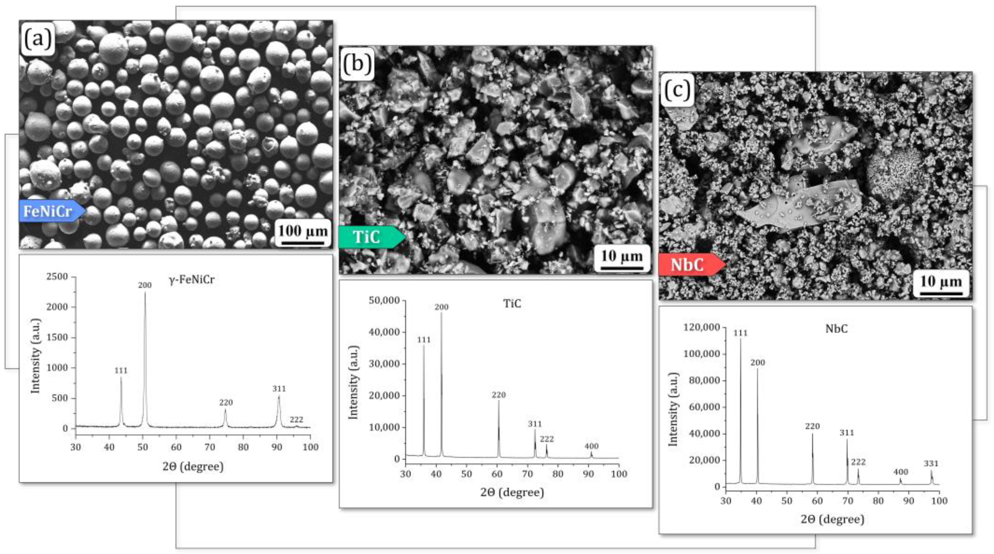
2.1. Feedstock Powders
2.2. Laser Cladding Parameters
2.3. Optical and Scanning Electron Microscopy
2.4. X-ray Diffraction Analysis
2.5. Raman Spectroscopy
2.6. Micromechanical Characterization
2.7. Tribological Tests
3. Results and Discussion
3.1. Microstructure and Phase and Chemical Composition
3.2. Raman Spectroscopy Phase Analysis
3.3. Mechanical Characterization
3.4. Tribological Analysis
4. Conclusions
- (1)
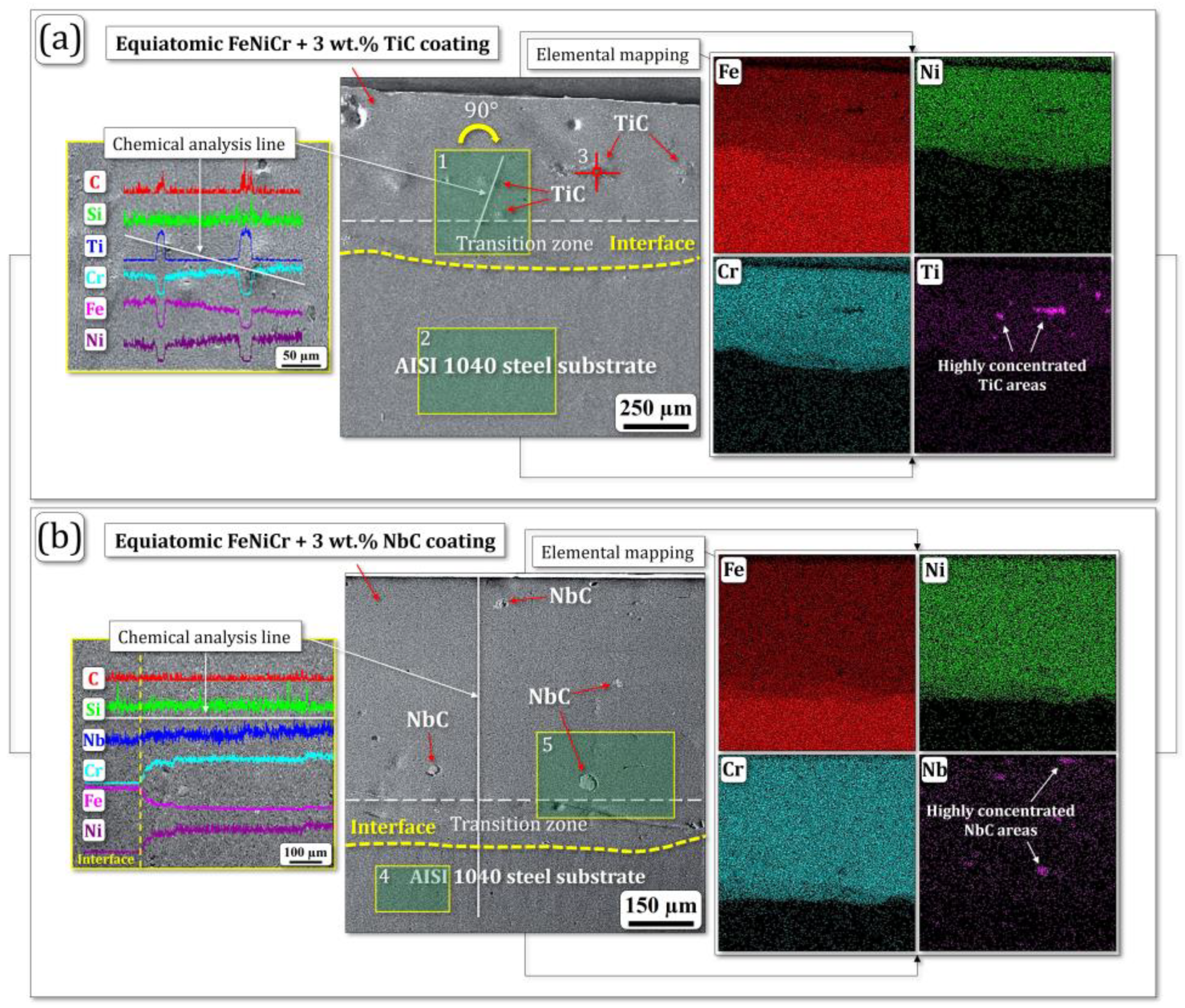
- The optical- and SEM-based microstructural analysis of the coatings demonstrated that their HNO3-etched cross-sections possess a uniformly deposited layer and contain a fairly homogeneous surface texture with a small number of pores and inclusions in the form of TiC and NbC phases. Their average thicknesses and compositional transition zones were 600 ± 20 μm and 150 ± 20 μm, respectively.
- (2)
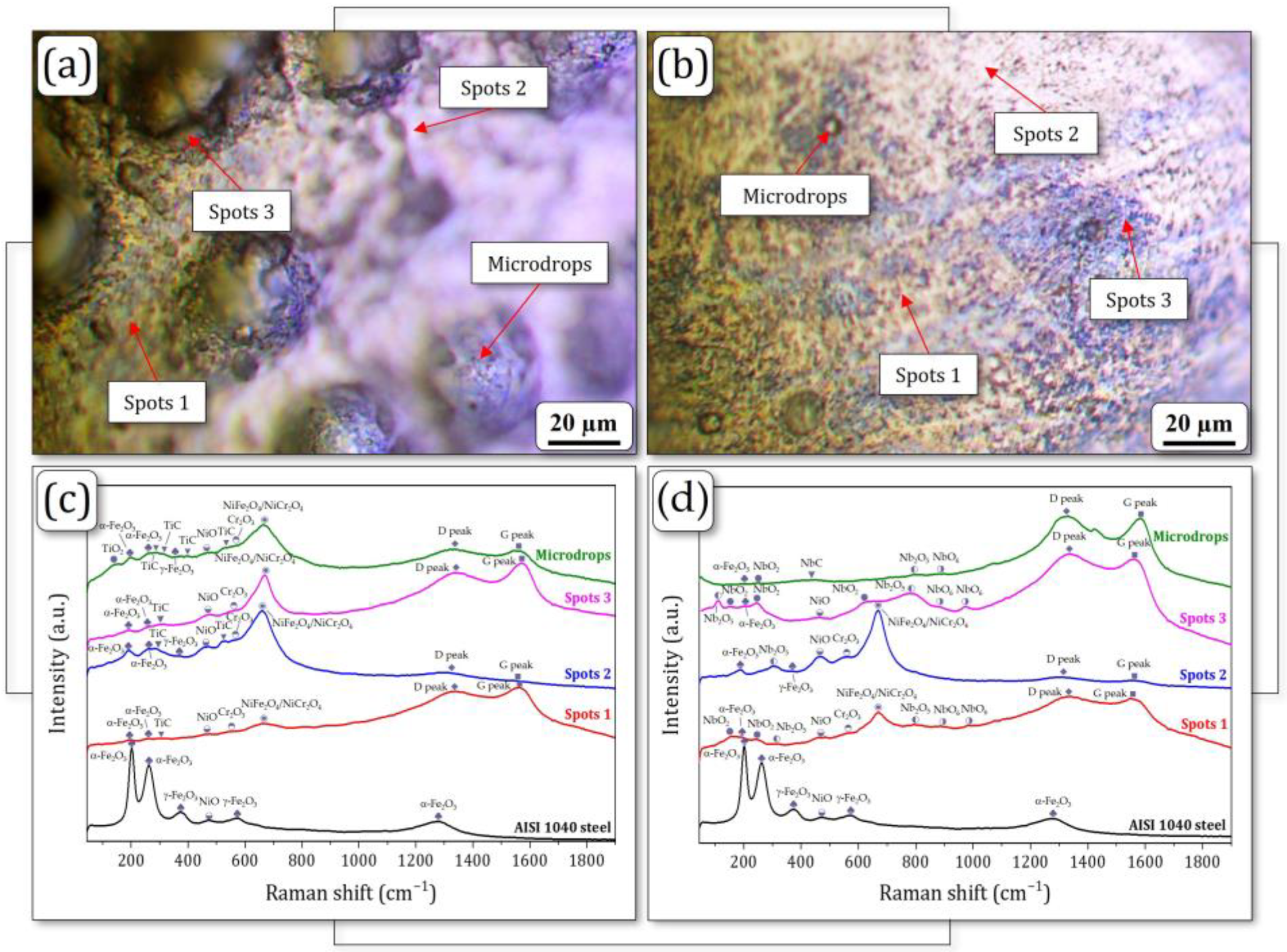
- Raman spectroscopy revealed that both coatings are primarily composed of a single FCC γ-phase (γ-FeNiCr). The FeNiCr + 3 wt.% TiC coating exhibited an additional TiC phase dispersed within the γ-FeNiCr matrix. In contrast, the FeNiCr + 3 wt.% NbC coating displayed a more homogeneous distribution of finely dispersed NbC phase throughout the composite, leading to enhanced mechanical behavior.
- (3)
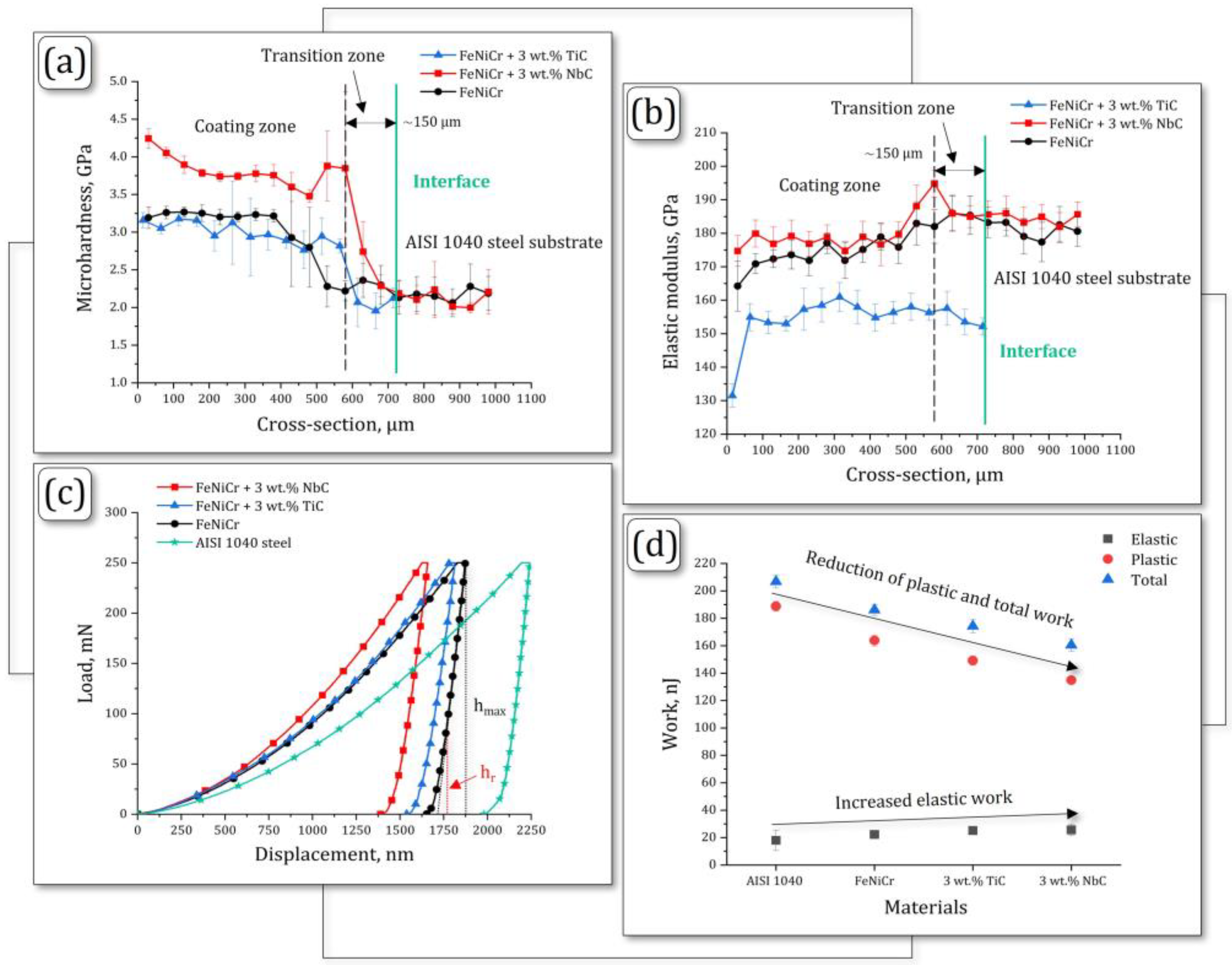
- Micromechanical characterization showed that the FeNiCr + 3 wt.% NbC coating exhibited higher average microhardness (3.8 GPa) and elastic modulus (180 GPa) compared to the FeNiCr + 3 wt.% TiC coating, which had values of ~3.2 GPa and ~156 GPa, respectively.
- (4)
- Both coatings significantly exceeded the AISI 1040 steel substrate in tribological performance. The FeNiCr + 3 wt.% TiC and FeNiCr + 3 wt.% NbC coatings exhibited substantial reductions in both weight loss (37% and 41%, respectively) and wear rate (33% and 42%, respectively) compared to the substrate material.
- (5)
- Reinforcement with finer NbC particles has a more significant effect on improving the mechanical and tribological performance of laser-cladded equiatomic FeNiCr-NbC coatings, making them advanced candidates for industrial applications.
Author Contributions
Funding
Institutional Review Board Statement
Informed Consent Statement
Data Availability Statement
Acknowledgments
Conflicts of Interest
References
- Rajak, D.K.; Wagh, P.H.; Menezes, P.L.; Chaudhary, A.; Kumar, R. Critical Overview of Coatings Technology for Metal Matrix Composites. J. Bio Tribo Corros. 2020, 6, 12. [Google Scholar] [CrossRef]
- Karmakar, R.; Maji, P.; Ghosh, S.K. A Review on the Nickel Based Metal Matrix Composite Coating. Met. Mater. Int. 2021, 27, 2134–2145. [Google Scholar] [CrossRef]
- Marshall, P. Austenitic Stainless Steels: Microstructure and Mechanical Properties; Elsevier Applied Science: London, UK, 1984; Available online: https://link.springer.com/book/9780853342779 (accessed on 3 June 2024).
- Kaladhar, M.; Venkata Subbaiah, K.; Srinivasa Rao, C.H. Machining of austenitic stainless steels—A review. Int. J. Mach. Mach. Mater. 2012, 12, 178–192. [Google Scholar] [CrossRef]
- Adrian Roberts, J.T. Structural Materials in Nuclear Power Systems; Plenum Press: New York, NY, USA, 1981. [Google Scholar] [CrossRef]
- Ma, B.M. Nuclear Reactor Materials and Applications; Van Nostrand Reinhold Co: New York, NY, USA, 1983; Available online: https://api.semanticscholar.org/CorpusID:138930351 (accessed on 10 June 2024).
- Chang, M.; Koul, A.K.; Au, P.; Terada, T. Damage tolerance of wrought alloy 718 Ni-Fe-base superalloy. J. Mater. Eng. Perform. 1994, 3, 356–366. [Google Scholar] [CrossRef]
- Takakuwa, O.; Ogawa, Y.; Yamabe, J.; Matsunaga, H. Hydrogen-induced ductility loss of precipitation-strengthened Fe-Ni-Cr-based superalloy. Mater. Sci. Eng. A 2019, 739, 335–342. [Google Scholar] [CrossRef]
- Hasanzadeh, A.; Hamedani, A.; Alahyarizadeh, G.; Minuchehr, A.; Aghaei, M. The Role of Chromium and Nickel on the Thermal and Mechanical Properties of FeNiCr Austenitic Stainless Steels under High Pressure and Temperature: A Molecular Dynamics Study. Mol. Simul. 2019, 45, 672–684. [Google Scholar] [CrossRef]
- Washko, S.D.; Aggen, G. Asm Handbook: Properties and Selection: Irons, Steels, and High-Performance Alloys, 10th ed.; ASM International: Materials Park, OH, USA, 1990; Volume 1. [Google Scholar] [CrossRef]
- AlMangour, B.; Baek, M.-S.; Grzesiak, D.; Lee, K.-A. Strengthening of stainless steel by titanium carbide addition and grain refinement during selective laser melting. Mater. Sci. Eng. A 2018, 712, 812–818. [Google Scholar] [CrossRef]
- Li, B.; Qian, B.; Xu, Y.; Liu, Z.; Zhang, J.; Xuan, F. Additive manufacturing of ultrafine-grained austenitic stainless steel matrix composite via vanadium carbide reinforcement addition and selective laser melting: Formation mechanism and strengthening effect. Mater. Sci. Eng. A 2019, 745, 495–508. [Google Scholar] [CrossRef]
- Liang, D.; Zhao, C.; Zhu, W.; Wei, P.; Jiang, F.; Zhang, Y.; Sun, Q.; Ren, F. Overcoming the strength-ductility trade-off via the formation of nanoscale Cr-rich precipitates in an ultrafine-grained FCC CrFeNi medium entropy alloy matrix. Mater. Sci. Eng. A 2019, 762, 138107. [Google Scholar] [CrossRef]
- Liang, D.; Zhao, C.; Zhu, W.; Wei, P.; Jiang, F.; Ren, F. Significantly Enhanced Wear Resistance of an Ultrafine-Grained CrFeNi Medium-Entropy Alloy at Elevated Temperatures. Metall. Mater. Trans. A 2020, 51, 2834–2850. [Google Scholar] [CrossRef]
- Chen, H.; Fang, Q.; Zhou, K.; Liu, Y.; Li, J. Unraveling atomic-scale crystallization and microstructural evolution of a selective laser melted FeCrNi medium-entropy alloy. CrystEngComm 2020, 22, 4136–4146. [Google Scholar] [CrossRef]
- Fu, A.; Liu, B.; Lu, W.; Liu, B.; Li, J.; Fang, Q.; Li, Z.; Liu, Y. A novel supersaturated medium entropy alloy with superior tensile properties and corrosion resistance. Scr. Mater. 2020, 186, 381–386. [Google Scholar] [CrossRef]
- Schneider, M.; Laplanche, G. Effects of temperature on mechanical properties and deformation mechanisms of the equiatomic CrFeNi medium-entropy alloy. Acta Mater. 2021, 204, 116470. [Google Scholar] [CrossRef]
- Zhou, Z.; Liu, B.; Guo, W.; Fu, A.; Duan, H.; Li, W. Corrosion behavior and mechanism of FeCrNi medium entropy alloy prepared by powder metallurgy. J. Alloys Compd. 2021, 867, 159094. [Google Scholar] [CrossRef]
- Wang, K.; Jin, X.; Zhang, Y.; Liaw, P.K.; Qiao, J. Dynamic tensile mechanisms and constitutive relationship in CrFeNi medium entropy alloys at room and cryogenic temperatures. Phys. Rev. Mater. 2021, 5, 113608. [Google Scholar] [CrossRef]
- Wang, K.; Wang, X.; Zhang, T.; Jin, X.; Yang, H.; Qiao, J. Tuning Cr-rich nanoprecipitation and heterogeneous structure in equiatomic CrFeNi medium-entropy stainless alloys. J. Iron Steel Res. Int. 2021, 29, 529–536. [Google Scholar] [CrossRef]
- Okulov, A.; Korobov, Y.; Stepchenkov, A.; Makarov, A.; Iusupova, O.; Korkh, Y.; Kuznetsova, T.; Kharanzhevskiy, E.; Liu, K. Mechanical and structural characterization of laser-cladded medium-entropy FeNiCr-B4C coatings. Materials 2023, 16, 5479. [Google Scholar] [CrossRef]
- Chen, L.; Lan, Y.; Cheng, Y.; Zeng, J.; Ma, Y.; Yu, S.; Ding, Z.; Liu, B.; Zhang, J.; Peng, H.; et al. Friction behavior and wear mechanism of laser cladded FeNiCr-WC composite coatings in comparison with different friction pairs. J. Mater. Res. Technol. 2024, 31, 1956–1973. [Google Scholar] [CrossRef]
- Shackelford, J.F.; Alexander, W. Materials Science and Engineering: Handbook; CRC Press LLC: Boca Raton, FL, USA, 2001. [Google Scholar] [CrossRef]
- Cuppari, M.; Santos, S. Physical Properties of the NbC Carbide. Metals 2016, 6, 250. [Google Scholar] [CrossRef]
- Okulov, A.V.; Iusupova, O.S.; Liu, K. Development of multicomponent hybrid powders based on titanium and niobium carbides as a promising material for laser cladding. E3S Web Conf. 2023, 413, 4012. [Google Scholar] [CrossRef]
- Miranda, R.M.; Gandra, J.P.; Vilaca, P.; Quintino, L.; Santos, T.G. Surface Modification by Solid State Processing; Elsevier: Amsterdam, The Netherlands; Woodhead Publishing Limited: Sawston, UK, 2014; Available online: http://www.sciencedirect.com/science/book/9780857094681 (accessed on 12 June 2024).
- Dezfuli, S.M.; Sabzi, M. Deposition of ceramic nanocomposite coatings by electroplating process: A review of layer-deposition mechanisms and effective parameters on the formation of the coating. Ceram. Int. 2019, 45, 21835–21842. [Google Scholar] [CrossRef]
- Singh, S.; Berndt, C.C.; Raman, R.K.S.; Singh, H.; Ang, A.S.M. Applications and Developments of Thermal Spray Coatings for the Iron and Steel Industry. Materials 2023, 16, 516. [Google Scholar] [CrossRef] [PubMed]
- Yang, J.; Liu, F.; Miao, X.; Yang, F. Influence of laser cladding process on the magnetic properties of WC–FeNiCr metal–matrix composite coatings. J. Mater. Process Technol. 2012, 212, 1862–1868. [Google Scholar] [CrossRef]
- Yang, J.; Miao, X.; Wang, X.; Chen, H.; Yang, F. Microstructure, magnetic properties and empirical electron theory calculations of laser cladding FeNiCr/60%WC composite coatings with Mo additions. Int. J. Refract. Hard Met. 2016, 54, 216–222. [Google Scholar] [CrossRef]
- Li, Y.; Dong, S.; He, P.; Yan, S.; Li, E.; Liu, X.; Xu, B. Microstructure characteristics and mechanical properties of new-type FeNiCr laser cladding alloy coating on nodular cast iron. J. Mater. Process. Technol. 2019, 269, 163–171. [Google Scholar] [CrossRef]
- Zhu, L.; Xue, P.; Lan, Q.; Meng, G.; Ren, Y.; Yang, Z.; Xu, P.; Liu, Z. Recent research and development status of laser cladding: A review. Opt. Laser Technol. 2021, 138, 106915. [Google Scholar] [CrossRef]
- Gokhfeld, N.V.; Okulov, A.V.; Filippov, M.A.; Estemirova, S.K.; Korobov, Y.S.; Morozov, S.O. The Comparative Analysis of the Fe–Cr–C–Ti–Al Coatings Synthesized by Laser, Arc and Hybrid Cladding Methods. Phys. Solid State 2022, 64, 356–361. [Google Scholar] [CrossRef]
- Wang, H.; Li, J.; Liu, K.; Xu, G.; Zhu, H.; Wang, J.; Xu, C.; Wang, L.; Okulov, A. Microstructural evolution and corrosion resistance property of in-situ Zr–C(B, Si)/Ni–Zr reinforced composite coatings on zirconium alloy by laser cladding. J. Mater. Res. Technol. 2023, 26, 530–541. [Google Scholar] [CrossRef]
- Wang, L.; Liu, K.; Li, J.; Chen, Z.; Wang, J.; Okulov, A. Interfacial microstructure and mechanical properties of diffusion bonded joints of additive manufactured 17-4 PH stainless steel and TC4 titanium alloy. Vacuum 2024, 219, 112709–112716. [Google Scholar] [CrossRef]
- Giurlani, W.; Zangari, G.; Gambinossi, F.; Passaponti, M.; Salvietti, E.; Benedetto, F.D.; Caporali, S.; Innocenti, M. Electroplating for Decorative Applications: Recent Trends in Research and Development. Coatings 2018, 8, 260. [Google Scholar] [CrossRef]
- Sathish, M.; Radhika, N.; Saleh, B. Duplex and Composite Coatings: A Thematic Review on Thermal Spray Techniques and Applications. Met. Mater. Int. 2023, 29, 1229–1297. [Google Scholar] [CrossRef]
- Alizadeh-Sh, M.; Marashi, S.P.H.; Ranjbarnodeh, E.; Shoja-Razavi, R.; Oliveira, J.P. Prediction of solidification cracking by an empirical-statistical analysis for laser cladding of Inconel 718 powder on a non-weldable substrate. Opt. Laser. Technol. 2020, 128, 106244. [Google Scholar] [CrossRef]
- Liu, K.; Wang, H.; Li, J.; Geng, S.; Chen, Z.; Okulov, A. A Review on Factors Infuencing Solidifcation Cracking of Magnesium Alloys During Welding. Met. Mater. Int. 2024, 30, 1723–1742. [Google Scholar] [CrossRef]
- ISO 14577-1:2015; Metallic Materials—Instrumented Indentation Test for Hardness and Materials Parameters—Part 1: Test Method. ISO: Geneva, Switzerland, 2015. Available online: https://www.iso.org/standard/56626.html (accessed on 10 June 2024).
- ASTM G132-96; Standard Test Method for Pin Abrasion Testing. ASTM International: West Conshohocken, PA, USA, 2018. Available online: https://www.astm.org/g0132-96.html (accessed on 12 June 2024).
- Kragelsky, I.V.; Dobychin, M.N.; Kombalov, V.S. Friction and Wear: Calculation Methods; Pergamon Press Ltd.: England, UK, 2013; Available online: https://api.semanticscholar.org/CorpusID:137239347 (accessed on 15 June 2024).
- Djafer, A.Z.A.; Saoula, N.; Madaoui, N.; Zerizer, A. Deposition and characterization of titanium carbide thin films by magnetron sputtering using Ti and TiC targets. Appl. Surf. Sci. 2014, 312, 57–62. [Google Scholar] [CrossRef]
- Poltorak, C.; Stüber, M.; Leiste, H.; Bergmaier, A.; Ulrich, S. Study of (Ti,Zr)C:H/a-C:H nanocomposite thin film formation by low temperature reactive high power impulse magnetron sputtering. Surf. Coat. Technol. 2020, 398, 125958. [Google Scholar] [CrossRef]
- Il’in, E.G.; Parshakov, A.S.; Kottsov, S.Y.; Razumov, M.I.; Gryzlov, D.Y. Preparation of Nanoporous Carbon from a Spherical NbC/C Nanocomposite and Its Properties. Inorg. Mater. 2022, 58, 1130–1136. [Google Scholar] [CrossRef]
- Novoa, L.; Cortes, L.E.; Gonzales, E.; Jimenez, A.; Cortes, L.G.; Ojeda, M.; Barbosa, A.L. Evaluation of Anticorrosive Effect of Niobium Carbide Coating Applied on Carbon Steel. Chem. Eng. Trans. 2017, 57, 1387–1392. [Google Scholar] [CrossRef]
- Cheng, Y.T.; Cheng, C.M. Relationships between hardness, elastic modulus and the work of indentation. Appl. Phys. Lett. 1998, 73, 614. [Google Scholar] [CrossRef]
- Mayrhofer, P.H.; Mitterer, C.; Musil, J. Structure-property relationships in single- and dual-phase nanocrystalline hard coatings. Surf. Coat. Technol. 2003, 174–175, 725–731. [Google Scholar] [CrossRef]
- Freitas Rodrigues, P.; Teixeira, R.S.; Le Sénéchal, N.V.; Braz Fernandes, F.M.; Paula, A.S. The Influence of the Soaking Temperature Rotary Forging and Solution Heat Treatment on the Structural and Mechanical Behavior in Ni-Rich NiTi Alloy. Materials 2022, 15, 63. [Google Scholar] [CrossRef]
- Page, T.F.; Hainsworth, S.V. Using nanoindentation techniques for the characterization of coated systems: A critique. Surf. Coat. Technol. 1993, 62, 201–208. [Google Scholar] [CrossRef]
- Petrzhik, M.I.; Levashov, E.A. Modern methods for investigating functional surfaces of advanced materials by mechanical contact testing. Crystallogr. Rep. 2007, 52, 966–974. [Google Scholar] [CrossRef]
- Milman, Y.V.; Chugunova, S.I.; Goncharova, I.V.; Golubenko, A.A. Plasticity of Materials Determined by the Indentation Method. Usp. Fiz. Met. 2018, 19, 271–307. [Google Scholar] [CrossRef]


| Material | Fe | Ti | Nb | Ni | Cr | Mn | C | O | S | P | Si |
|---|---|---|---|---|---|---|---|---|---|---|---|
| FeNiCr | Base | - | - | 35.6 | 29.8 | - | 0.37 | - | <0.001 | 0.008 | 1.62 |
| AISI 1040 steel | - | - | - | - | 0.6–0.9 | 0.37–0.44 | - | ≤0.05 | ≤0.04 | 0.15–0.35 | |
| TiC | - | 80.8 | - | - | - | - | 18.0 | 1.2 | - | - | - |
| NbC | - | - | 89.05 | - | - | - | 10.3 | 0.65 | - | - | - |
| Selected Area | Fe | Ni | Cr | Ti | Nb | C |
|---|---|---|---|---|---|---|
| 1 | 36.62 | 29.30 | 28.75 | 3.72 | - | 1.61 |
| 2 | 98.57 | 0.68 | 0.41 | - | - | 0.34 |
| 3 | 4.62 | 1.28 | 2.57 | 83.71 | - | 7.82 |
| 4 | 98.72 | 0.59 | 0.32 | - | - | 0.37 |
| 5 | 33.30 | 31.59 | 30.85 | - | 2.87 | 1.39 |
| AISI 1040 Steel | FeNiCr + 3 wt.% TiC Peak Maximum Position, cm−1 | Interpretation | |||
| Spots1 | Spots2 | Spots3 | Microdrops | ||
| - | - | - | - | 149 | TiO2 |
| 202 | 196 | 191 | 191 | 197 | α-Fe2O3 |
| 262 | 260 | 266 | 266 | 264 | α-Fe2O3 |
| - | - | 283 | - | 285 | TiC |
| - | 311 | - | 306 | 316 | TiC |
| 373 | - | 367 | - | 374 | γ-Fe2O3 |
| - | - | - | - | 398 | TiC |
| 470 | 472 | 468 | 475 | 470 | NiO |
| - | - | 526 | - | 526 | TiC |
| - | 547 | 556 | 549 | 560 | Cr2O3 |
| 570 | - | - | - | - | γ-Fe2O3 |
| - | 665 | 661 | 669 | 665 | NiFe2O4/NiCr2O4 |
| 1276 | - | - | - | - | α-Fe2O3 |
| - | 1338 | 1315 | 1345 | 1327 | Amorphous carbon (D peak) |
| - | 1561 | 1548 | 1572 | 1555 | Amorphous carbon (G peak) |
| AISI 1040 Steel | FeNiCr + 3 wt.% NbC Peak Maximum Position, cm−1 | Interpretation | |||
| Spots 1 | Spots 2 | Spots 3 | Microdrops | ||
| - | - | - | 112 | - | Nb2O5 |
| - | 163 | - | 153 | - | NbO2 |
| 202 | 195 | 189 | 197 | 198 | α-Fe2O3 |
| - | 245 | - | 244 | 249 | NbO2 |
| 262 | - | - | - | - | α-Fe2O3 |
| - | 310 | 303 | - | - | Nb2O5 |
| 373 | - | 370 | - | - | γ-Fe2O3 |
| - | - | - | - | 434 | NbC |
| 470 | 472 | 466 | 461 | - | NiO |
| - | 560 | 555 | - | - | Cr2O3 |
| 570 | - | - | - | - | γ-Fe2O3 |
| - | - | - | 638 | - | NbO2 |
| - | 671 | 667 | - | - | NiFe2O4/NiCr2O4 |
| - | 797 | - | 782 | 799 | Nb2O5 |
| - | 887 | - | 878 | 890 | NbO6 |
| - | 984 | - | 973 | - | NbO6 |
| 1276 | - | - | - | - | α-Fe2O3 |
| - | 1334 | 1310 | 1332 | 1326 | Amorphous carbon (D peak) |
| - | 1549 | 1560 | 1560 | 1583 | Amorphous carbon (G peak) |
| Material | Work, nJ | HIT, GPa | E*, GPa | HIT/E* | HIT3/E*2, GPa | Re, % | δA | ||
|---|---|---|---|---|---|---|---|---|---|
| Elastic | Plastic | Total | |||||||
| AISI 1040 steel | 18.02 | 188.79 | 206.81 | 2.154 | 184.68 | 0.0117 | 0.0003 | 3.85 | 0.90 |
| FeNiCr | 22.30 | 163.84 | 186.14 | 3.228 | 172.11 | 0.0188 | 0.0011 | 5.90 | 0.86 |
| FeNiCr + 3 wt.% TiC (abbreviated as TiC) | 25.16 | 149.12 | 174.28 | 3.235 | 155.71 | 0.0208 | 0.0014 | 6.71 | 0.83 |
| FeNiCr + 3 wt.% NbC (abbreviated as NbC) | 25.68 | 134.80 | 160.48 | 3.810 | 180.09 | 0.0212 | 0.0017 | 6.86 | 0.82 |
| Comparative analysis (change (↓↑) in %) | |||||||||
| TiC vs. AISI 1040 steel | 40 ↑ | 21 ↓ | 16 ↓ | 50 ↑ | 16 ↓ | 78 ↑ | 367 ↑ | 74 ↑ | 8 ↓ |
| NbC vs. AISI 1040 steel | 43 ↑ | 29 ↓ | 22 ↓ | 77 ↑ | 2 ↓ | 81 ↑ | 467 ↑ | 78 ↑ | 9 ↓ |
| TiC vs. FeNiCr | 13 ↑ | 9 ↓ | 6 ↓ | 0 | 10 ↓ | 11 ↑ | 27 ↑ | 14 ↑ | 3 ↓ |
| NbC vs. FeNiCr | 15 ↑ | 18 ↓ | 14 ↓ | 18 ↑ | 5 ↑ | 13 ↑ | 55 ↑ | 16 ↑ | 5 ↓ |
| NbC vs. TiC | 2 ↑ | 10 ↓ | 8 ↓ | 18 ↑ | 16 ↑ | 2 ↑ | 21 ↑ | 2 ↑ | 1 ↓ |
| Sample | Weight Loss, mg | Wear Rate, Ih |
|---|---|---|
| FeNiCr + 3 wt.% NbC | 26.28 ± 1.27 | (3.73 ± 0.18) × 10−6 |
| FeNiCr + 3 wt.% TiC | 27.83 ± 1.16 | (4.29 ± 0.18) × 10−6 |
| FeNiCr | 27.89 ± 1.34 | (4.31 ± 0.21) × 10−6 |
| AISI 1040 steel | 44.44 ± 1.72 | (6.42 ± 0.25) × 10−6 |
Disclaimer/Publisher’s Note: The statements, opinions and data contained in all publications are solely those of the individual author(s) and contributor(s) and not of MDPI and/or the editor(s). MDPI and/or the editor(s) disclaim responsibility for any injury to people or property resulting from any ideas, methods, instructions or products referred to in the content. |
© 2024 by the authors. Licensee MDPI, Basel, Switzerland. This article is an open access article distributed under the terms and conditions of the Creative Commons Attribution (CC BY) license (https://creativecommons.org/licenses/by/4.0/).
Share and Cite
Okulov, A.; Iusupova, O.; Liu, K.; Li, J.; Stepchenkov, A.; Zavalishin, V.; Korkh, Y.; Kuznetsova, T.; Mugada, K.K.; Moganraj, A. Micromechanical and Tribological Performance of Laser-Cladded Equiatomic FeNiCr Coatings Reinforced with TiC and NbC Particles. Materials 2024, 17, 4686. https://doi.org/10.3390/ma17194686
Okulov A, Iusupova O, Liu K, Li J, Stepchenkov A, Zavalishin V, Korkh Y, Kuznetsova T, Mugada KK, Moganraj A. Micromechanical and Tribological Performance of Laser-Cladded Equiatomic FeNiCr Coatings Reinforced with TiC and NbC Particles. Materials. 2024; 17(19):4686. https://doi.org/10.3390/ma17194686
Chicago/Turabian StyleOkulov, Artem, Olga Iusupova, Kun Liu, Jie Li, Alexander Stepchenkov, Vladimir Zavalishin, Yulia Korkh, Tatyana Kuznetsova, Krishna Kishore Mugada, and Arivarasu Moganraj. 2024. "Micromechanical and Tribological Performance of Laser-Cladded Equiatomic FeNiCr Coatings Reinforced with TiC and NbC Particles" Materials 17, no. 19: 4686. https://doi.org/10.3390/ma17194686
APA StyleOkulov, A., Iusupova, O., Liu, K., Li, J., Stepchenkov, A., Zavalishin, V., Korkh, Y., Kuznetsova, T., Mugada, K. K., & Moganraj, A. (2024). Micromechanical and Tribological Performance of Laser-Cladded Equiatomic FeNiCr Coatings Reinforced with TiC and NbC Particles. Materials, 17(19), 4686. https://doi.org/10.3390/ma17194686