
Production and Characterization of Fine-Grained Multielement AlCoxCrFeNi (x = 1, 0.75, 0.5) Alloys for High-Temperature Applications

 , , and
Abstract
:1. Introduction
2. Materials and Methods
3. Results and Discussion
3.1. Milled Powders
3.2. Sintered Samples
- -
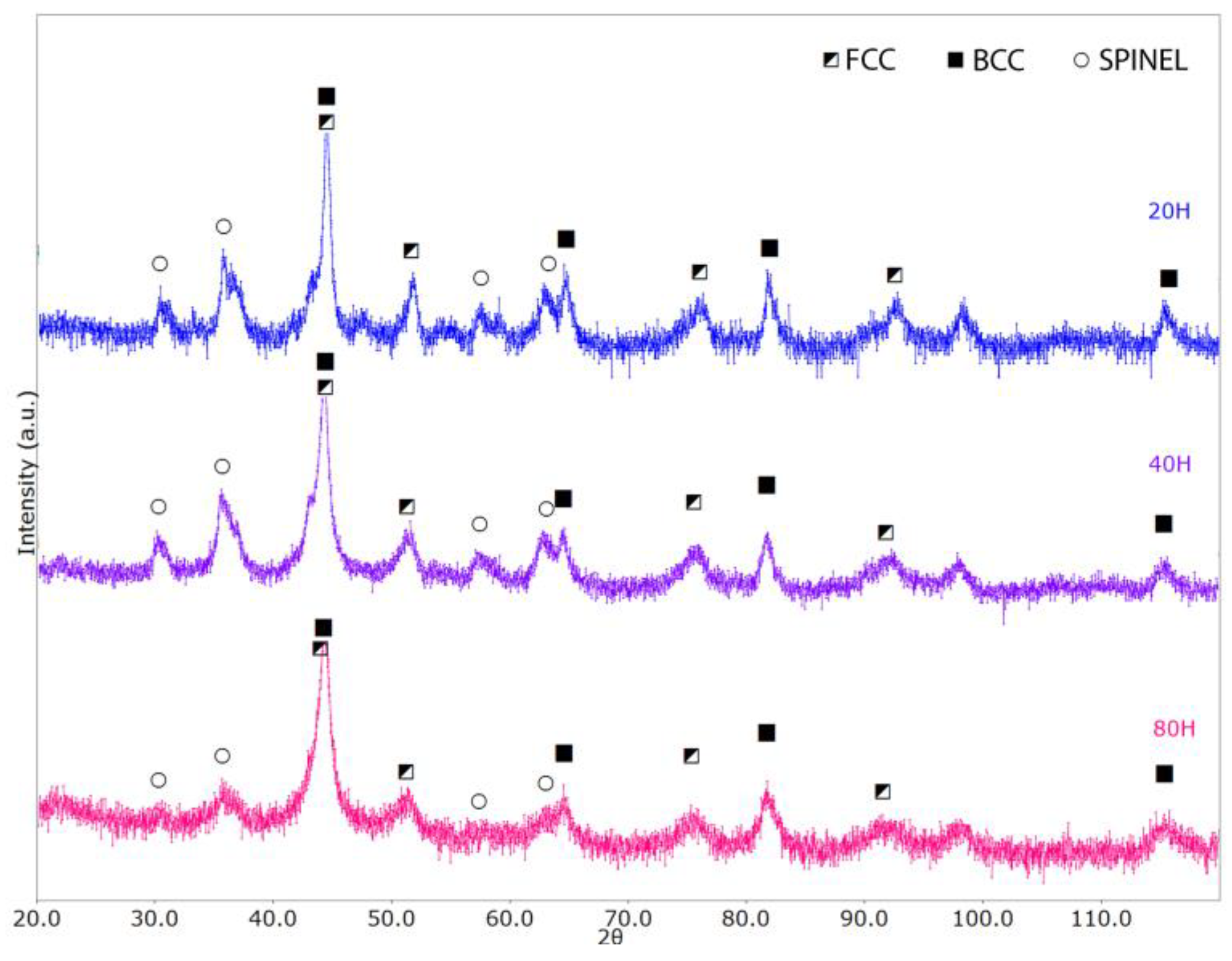
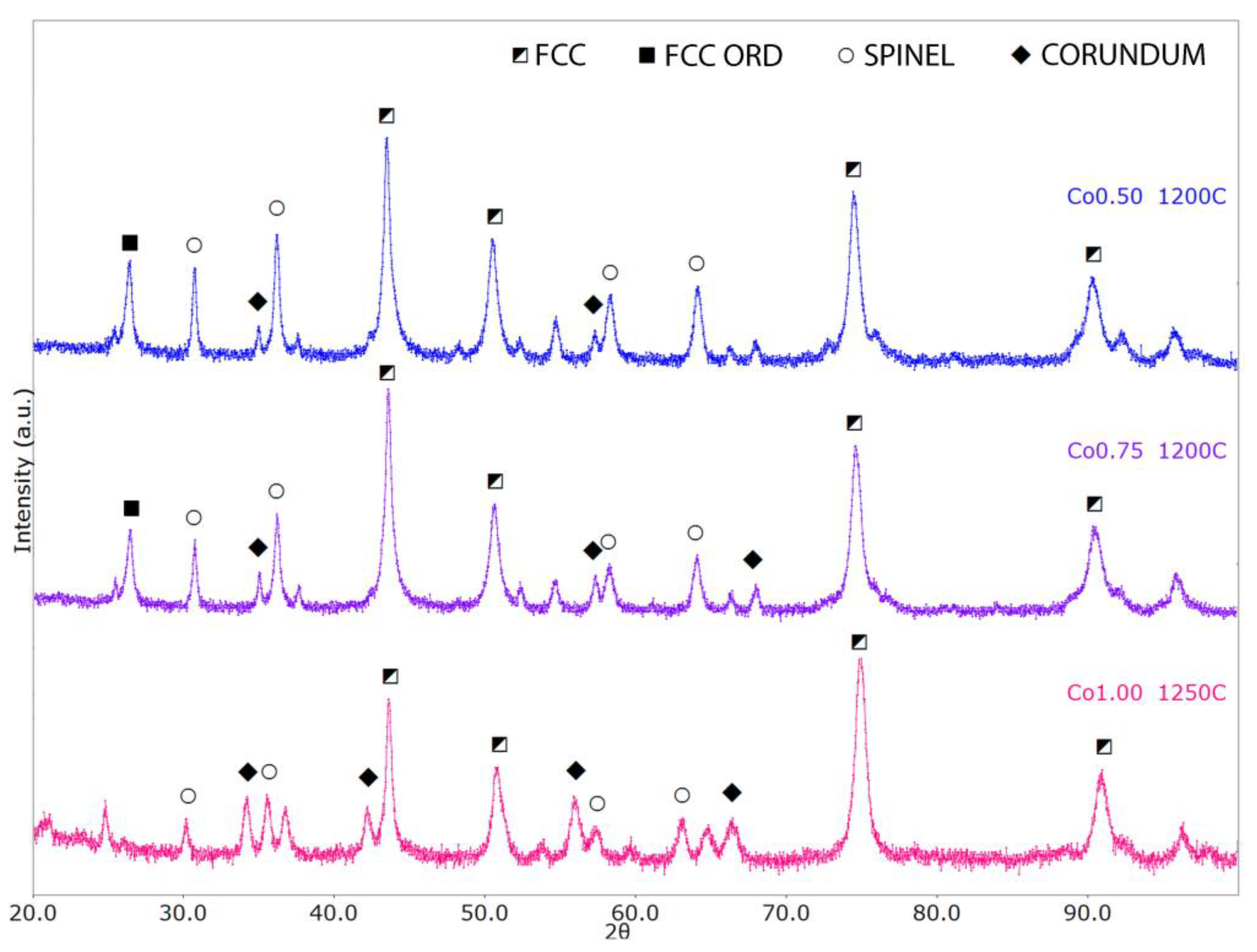
- With an increase in the Co content, the FCC lattice exhibits lattice/cell volume shrinking, whereas the two oxides show the opposite behavior. In general, we can expect larger unit cell volumes (with respect to the reference structures) to be associated with substitutional disorder, whereas smaller volumes can be possibly associated with particular chemical element segregation.
- -
- The FCC crystal structure presents a decrease in the lattice parameter with increasing Co content, with values varying between 3.60 Å and 3.58 Å. For reference, Ni, Co, and g-Fe standard FCC lattice parameters are, respectively, 3.53 Å, 3.55 Å, and 3.59 Å.
- -
- The spinel cubic lattice exhibits a quite significant lattice parameter increase from 8.21 Å to 8.32 Å with increasing Co content, with reference structures like Co3O4 and Fe3O4 having lattice parameters equal to 8.08 Å to 8.39 Å, respectively. This could also be related to the Al-depletion in the matrix consequent to the Al2O3 phase increase.
- -
- For the Al2O3-like lattice, we have lattice parameters varying between 4.78 Å and 4.87 Å (a) and between 13.03 Å and 13.28 Å (c); for comparison, the reference Al2O3 and Cr2O3 structures have lattice parameters values equal to a = 4.76 Å, c = 12.99 Å and a = 4.96 Å, c = 13.6 Å, respectively. The α-Al2O3 phase was also observed by Wang et al. [17], who obtained the alloy via mechanical milling and SPS. This oxide shows high chemical stability and gives oxidation resistance.
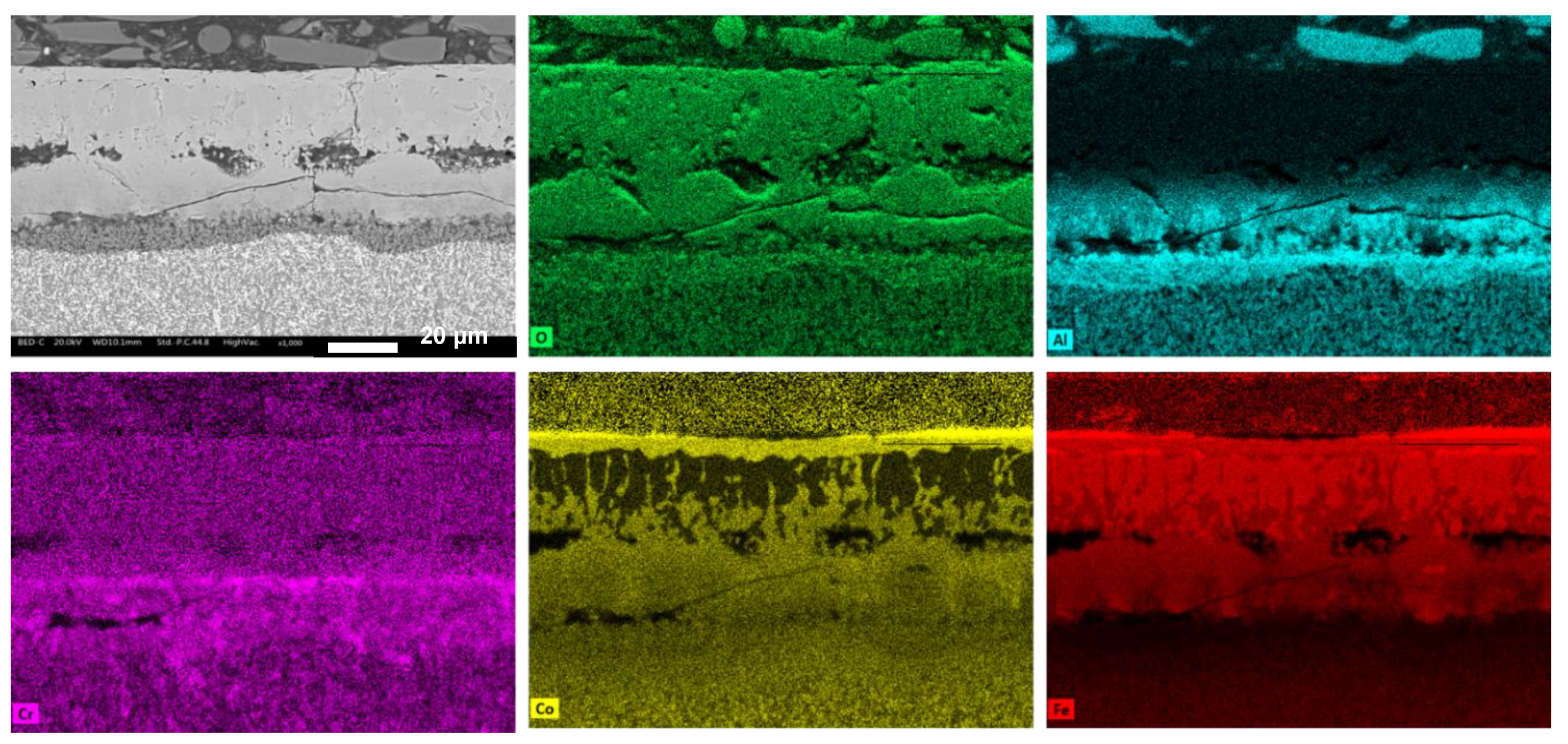
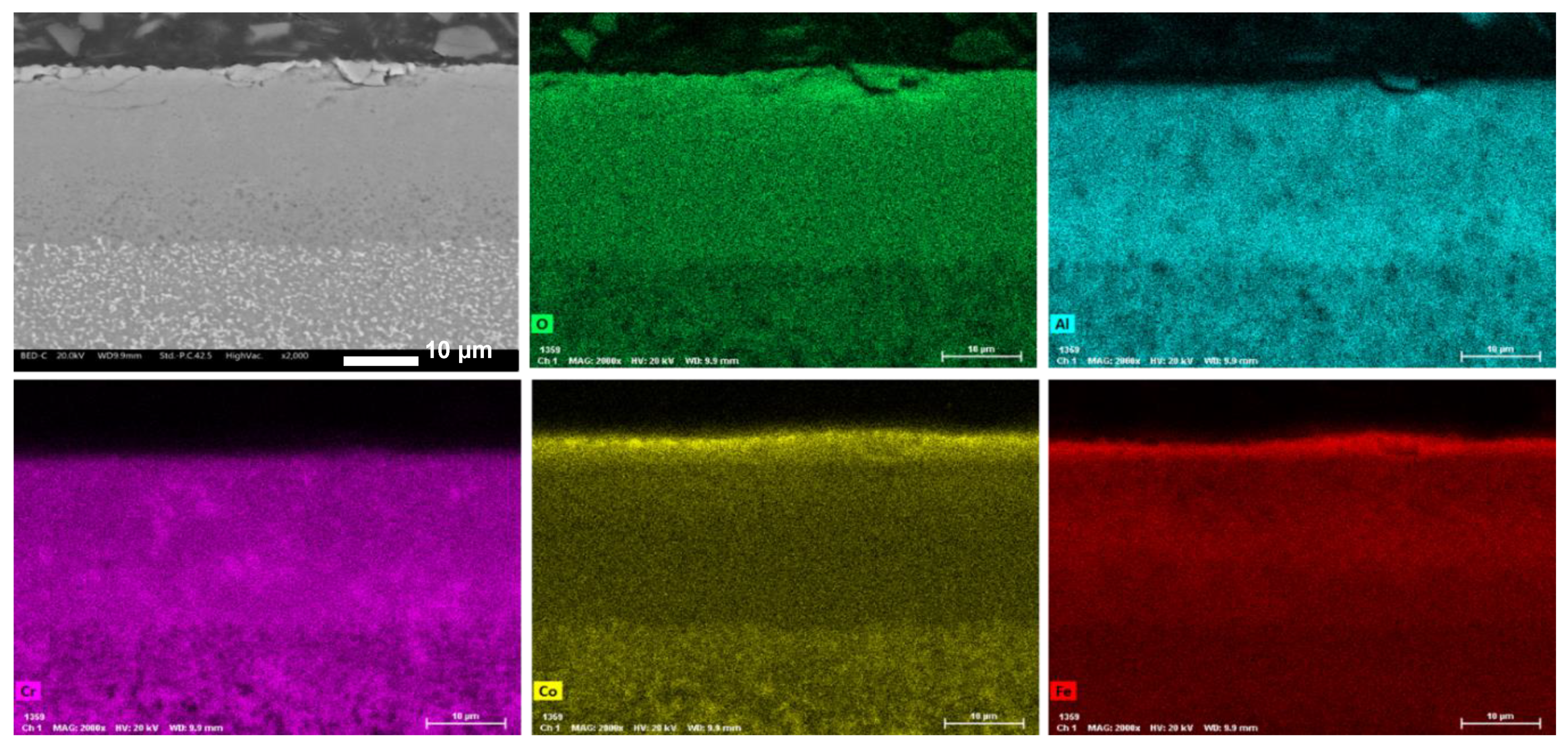
3.3. Oxidation Behavior
- -
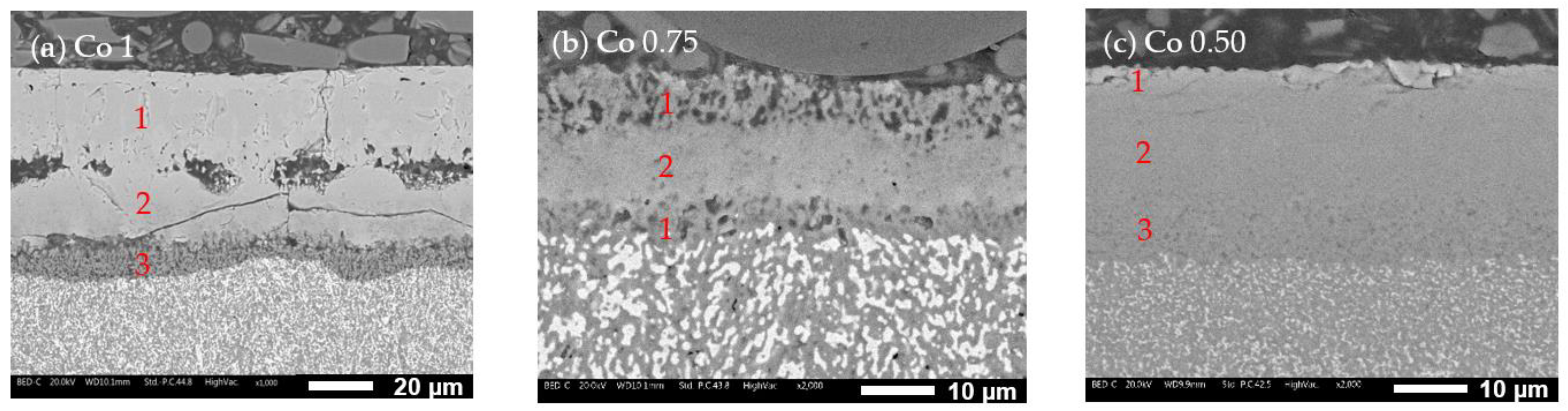
- Co1 (Figure 10a): The oxide layer appears to be divided into three parts. The outermost layer (layer 1) is characterized by grain-like structures. Below this, separated by poor bonding with many longitudinal open cracks, is a second layer (layer 2) with no visible grains and numerous cracks, indicating brittleness. The third layer (layer 3), in contact with the alloy surface, is much thinner and shows some microporosity.
- -
- Co0.75 (Figure 10b): This alloy features a “sandwich” layer structure, with the top and bottom parts exhibiting similar microporosity (layers 1), while the middle layer (layer 2) is more compact.
- -
- Co0.50 (Figure 10c): This alloy also has three layers: an external very thin layer with various cracks (layer 1), a thicker compact internal layer in the middle (layer 2), and a bottom layer similar to layer 2 but with diffused microporosity (layer 3).
4. Conclusions
Author Contributions
Funding
Institutional Review Board Statement
Informed Consent Statement
Data Availability Statement
Conflicts of Interest
References
- Cantor, B.; Chang, I.T.H.; Knight, P.; Vincent, A.J.B. Microstructural Development in Equiatomic Multicomponent Alloys. Mater. Sci. Eng. A 2004, 375–377, 213–218. [Google Scholar] [CrossRef]
- Yeh, J.W.; Chen, S.K.; Lin, S.J.; Gan, J.Y.; Chin, T.S.; Shun, T.T.; Tsau, C.H.; Chang, S.Y. Nanostructured High-Entropy Alloys with Multiple Principal Elements: Novel Alloy Design Concepts and Outcomes. Adv. Eng. Mater. 2004, 6, 299–303. [Google Scholar] [CrossRef]
- Gao, M.C.; Liaw, P.K.; Yeh, J.W.; Zhang, Y. High-Entropy Alloys: Fundamentals and Applications; Springer International Publisher: Cham, Switzerland, 2016; pp. 1–516. [Google Scholar] [CrossRef]
- Zhang, Y.; Zuo, T.T.; Tang, Z.; Gao, M.C.; Dahmen, K.A.; Liaw, P.K.; Lu, Z.P. Microstructures and Properties of High-Entropy Alloys. Prog. Mater. Sci. 2014, 61, 1–93. [Google Scholar] [CrossRef]
- Jeong, H.I.; Kim, J.H.; Lee, C.M. Manufacturing of Ni-Co-Fe-Cr-Al-Ti High-Entropy Alloy Using Directed Energy Deposition and Evaluation of Its Microstructure, Tensile Strength, and Microhardness. Materials 2024, 17, 4297. [Google Scholar] [CrossRef]
- Liu, C.M.; Wang, H.M.; Zhang, S.Q.; Tang, H.B.; Zhang, A.L. Microstructure and Oxidation Behavior of New Refractory High Entropy Alloys. J. Alloys Compd. 2014, 583, 162–169. [Google Scholar] [CrossRef]
- Shi, Y.; Collins, L.; Feng, R.; Zhang, C.; Balke, N.; Liaw, P.K.; Yang, B. Homogenization of AlxCoCrFeNi High-Entropy Alloys with Improved Corrosion Resistance. Corros. Sci. 2018, 133, 120–131. [Google Scholar] [CrossRef]
- Lim, K.R.; Lee, K.S.; Lee, J.S.; Kim, J.Y.; Chang, H.J.; Na, Y.S. Dual-Phase High-Entropy Alloys for High-Temperature Structural Applications. J. Alloys Compd. 2017, 728, 1235–1238. [Google Scholar] [CrossRef]
- Butler, T.M.; Weaver, M.L. Oxidation Behavior of Arc Melted AlCoCrFeNi Multi-Component High-Entropy Alloys. J. Alloys Compd. 2016, 674, 229–244. [Google Scholar] [CrossRef]
- Zhang, H.; Wang, Q.T.; Tang, Q.H.; Dai, P.Q. High Temperature Oxidation Property of Al0.5FeCoCrNi (Si0.2, Ti0.5) High Entropy Alloys. Corros. Prot. 2013, 34, 561–565. [Google Scholar]
- Xu, Q.L.; Zhang, Y.; Liu, S.H.; Li, C.J.; Li, C.X. High-Temperature Oxidation Behavior of CuAlNiCrFe High-Entropy Alloy Bond Coats Deposited Using High-Speed Laser Cladding Process. Surf. Coat. Technol. 2020, 398, 126093. [Google Scholar] [CrossRef]
- Huang, C.; Zhang, Y.; Shen, J.; Vilar, R. Thermal Stability and Oxidation Resistance of Laser Clad TiVCrAlSi High Entropy Alloy Coatings on Ti-6Al-4V Alloy. Surf. Coat. Technol. 2011, 206, 1389–1395. [Google Scholar] [CrossRef]
- Huang, P.K.; Yeh, J.W.; Shun, T.T.; Chen, S.K. Multi-Principal-Element Alloys with Improved Oxidation and Wear Resistance for Thermal Spray Coating. Adv. Eng. Mater. 2004, 6, 74–78. [Google Scholar] [CrossRef]
- Tang, Z.; Senkov, O.N.; Parish, C.M.; Zhang, C.; Zhang, F.; Santodonato, L.J.; Wang, G.; Zhao, G.; Yang, F.; Liaw, P.K. Tensile Ductility of an AlCoCrFeNi Multi-Phase High-Entropy Alloy through Hot Isostatic Pressing (HIP) and Homogenization. Mater. Sci. Eng. A 2015, 647, 229–240. [Google Scholar] [CrossRef]
- Yang, T.; Xia, S.; Liu, S.; Wang, C.; Liu, S.; Zhang, Y.; Xue, J.; Yan, S.; Wang, Y. Effects of AL Addition on Microstructure and Mechanical Properties of AlxCoCrFeNi High-Entropy Alloy. Mater. Sci. Eng. A 2015, 648, 15–22. [Google Scholar] [CrossRef]
- Huang, J.C. Evaluation of Tribological Behavior of Al-Co-Cr-Fe-Ni High Entropy Alloy Using Molecular Dynamics Simulation. Scanning 2012, 34, 325–331. [Google Scholar] [CrossRef]
- Wang, W.R.; Wang, W.L.; Wang, S.C.; Tsai, Y.C.; Lai, C.H.; Yeh, J.W. Effects of Al Addition on the Microstructure and Mechanical Property of Al XCoCrFeNi High-Entropy Alloys. Intermetallics 2012, 26, 44–51. [Google Scholar] [CrossRef]
- Daily Metal Prices. Available online: https://www.dailymetalprice.com/ (accessed on 28 August 2024).
- Pollock, T.M.; Tin, S. Nickel-Based Superalloys for Advanced Turbine Engines: Chemistry, Microstructure, and Properties. J. Propuls. Power 2006, 22, 361–374. [Google Scholar] [CrossRef]
- Senkov, O.N.; Jensen, J.K.; Pilchak, A.L.; Miracle, D.B.; Fraser, H.L. Compositional Variation Effects on the Microstructure and Properties of a Refractory High-Entropy Superalloy AlMo0.5NbTa0.5TiZr. Mater. Des. 2018, 139, 498–511. [Google Scholar] [CrossRef]
- Senkov, O.N.; Gorsse, S.; Miracle, D.B. High Temperature Strength of Refractory Complex Concentrated Alloys. Acta Mater. 2019, 175, 394–405. [Google Scholar] [CrossRef]
- Srikanth, M.; Raja Annamalai, A.; Muthuchamy, A.; Jen, C.P. A Review of the Latest Developments in the Field of Refractory High-Entropy Alloys. Crystals 2021, 11, 612. [Google Scholar] [CrossRef]
- Rame, J.; Utada, S.; Bortoluci Ormastroni, L.M.; Mataveli-Suave, L.; Menou, E.; Després, L.; Kontis, P.; Cormier, J. Platinum-containing new generation nickel-based superalloy for single crystalline applications. In The Minerals, Metals and Materials Series; Springer International Publishing: New York, NY, USA, 2020. [Google Scholar]
- Atli, K.C.; Karaman, I. A Short Review on the Ultra-High Temperature Mechanical Properties of Refractory High Entropy Alloys. Front. Met. Alloys 2023, 2, 1135826. [Google Scholar] [CrossRef]
- Tsai, K.Y.; Tsai, M.H.; Yeh, J.W. Sluggish Diffusion in Co-Cr-Fe-Mn-Ni High-Entropy Alloys. Acta Mater. 2013, 61, 4887–4897. [Google Scholar] [CrossRef]
- Mehta, A.; Sohn, Y. Investigation of Sluggish Diffusion in FCC Al0.25CoCrFeNi High-Entropy Alloy. Mater. Res. Lett. 2021, 9, 239–246. [Google Scholar] [CrossRef]
- Gorr, B.; Azim, M.; Christ, H.J.; Mueller, T.; Schliephake, D.; Heilmaier, M. Phase Equilibria, Microstructure, and High Temperature Oxidation Resistance of Novel Refractory High-Entropy Alloys. J. Alloys Compd. 2015, 624, 270–278. [Google Scholar] [CrossRef]
- Holcomb, G.R.; Tylczak, J.; Carney, C. Oxidation of CoCrFeMnNi High Entropy Alloys. JOM 2015, 67, 2326–2339. [Google Scholar] [CrossRef]
- Huang, G.Q.; Chou, T.H.; Liu, S.F.; Ju, J.; Gan, J.; Yang, T.; Feng, X.M.; Shen, Y.F.; Gao, J.C.; Li, M.S.; et al. Effect of Initial Grain Size on Oxidation Resistance of L12-Strengthened Al-Fe-Cr-Cu-Ni High-Entropy Alloy at 900 °C. Appl. Surf. Sci. 2024, 652, 159285. [Google Scholar] [CrossRef]
- Zhou, Z.; Zhang, X.; Peng, X.; Xie, Y.; Yang, S.; Li, H.; Guo, H. Insights into the Effects of Grain Size Variation and FCC Phase Formation on the Oxidation Behavior of Laser Additively Manufactured BCC AlCoCrFeNi High Entropy Alloy. Corros. Sci. 2024, 239, 112416. [Google Scholar] [CrossRef]
- Cai, S.; Cui, J.; Dong, Z.; Lv, W.; Yang, B.; Han, D.; Wang, J. Enhancing Oxidation Resistance via Grain Boundary Engineering in L12-Strengthened Medium Entropy Alloys. J. Mater. Sci. Technol. 2024; in press. [Google Scholar] [CrossRef]
- Lu, J.; Li, L.; Zhang, H.; Chen, Y.; Luo, L.; Zhao, X.; Guo, F.; Xiao, P. Oxidation Behavior of Gas-Atomized AlCoCrFeNi High-Entropy Alloy Powder at 900–1100 °C. Corros. Sci. 2021, 181, 109257. [Google Scholar] [CrossRef]
- Kaplin, C.; Brochu, M. The Effect of Grain Size on the Oxidation of NiCoCrAlY. Appl. Surf. Sci. 2014, 301, 258–263. [Google Scholar] [CrossRef]
- Chen, Y.; Zhao, X.; Xiao, P. Effect of Microstructure on Early Oxidation of MCrAlY Coatings. Acta Mater. 2018, 159, 150–162. [Google Scholar] [CrossRef]
- Lu, J.; Chen, Y.; Zhang, H.; Li, L.; Fu, L.; Zhao, X.; Guo, F.; Xiao, P. Effect of Al Content on the Oxidation Behavior of Y/Hf-Doped AlCoCrFeNi High-Entropy Alloy. Corros. Sci. 2020, 170, 108691. [Google Scholar] [CrossRef]
- Lu, J.; Zhang, H.; Chen, Y.; Li, L.; Liu, X.; Xiao, W.; Ni, N.; Zhao, X.; Guo, F.; Xiao, P. Y-Doped AlCoCrFeNi2.1 Eutectic High-Entropy Alloy with Excellent Oxidation Resistance and Structure Stability at 1000 °C and 1100 °C. Corros. Sci. 2021, 180, 109191. [Google Scholar] [CrossRef]
- Zhu, J.; Lu, S.; Jin, Y.; Xu, L.; Xu, X.; Yin, C.; Jia, Y. High-Temperature Oxidation Behaviours of AlCoCrFeNi High-Entropy Alloy at 1073–1273 K. Oxid. Met. 2020, 94, 265–281. [Google Scholar] [CrossRef]
- Huang, A.; Li, L.; Liu, X.; Zhang, H.; Zhang, X.; Lu, J.; Chen, Y.; Zhao, X. Phase Transformation-Induced TGO Rumpling Failure of an AlCoCrFeNi High-Entropy Alloy after Isothermal Oxidation at 1200 °C. Scr. Mater. 2024, 239, 115817. [Google Scholar] [CrossRef]
- Butler, T.M.; Pavel, M.J.; Weaver, M.L. The Effect of Annealing on the Microstructures and Oxidation Behaviors of AlCoCrFeNi Complex Concentrated Alloys. J. Alloys Compd. 2023, 956, 170391. [Google Scholar] [CrossRef]
- Garg, M.; Grewal, H.S.; Sharma, R.K.; Arora, H.S. Enhanced Oxidation Resistance of Ultrafine-Grain Microstructure AlCoCrFeNi High Entropy Alloy. ACS Omega 2022, 7, 12589–12600. [Google Scholar] [CrossRef] [PubMed]
- Gabbott, P. Principles and Applications of Thermal Analysis; Wiley-Blackwell: Hoboken, NJ, USA, 2008. [Google Scholar]
- Campos, R.P.; Cuevas, A.C.; Esparza Muñoz, R.A. Characterization of Metals and Alloys; Momentum Press: New York, NY, USA, 2016. [Google Scholar]
- Samal, S. Oxidation of Metal. In Encyclopedia of Materials: Metals and Alloys; Elsevie: Amsterdam, The Netherlands, 2021. [Google Scholar]
- Sheikh, S.; M’Saoubi, R.; Flasar, P.; Schwind, M.; Persson, T.; Yang, J.; Llanes, L. Fracture Toughness of Cemented Carbides: Testing Method and Microstructural Effects. Int. J. Refract. Met. Hard Mater. 2015, 49, 153–160. [Google Scholar] [CrossRef]
- Shivam, V.; Basu, J.; Pandey, V.K.; Shadangi, Y.; Mukhopadhyay, N.K. Alloying Behaviour, Thermal Stability and Phase Evolution in Quinary AlCoCrFeNi High Entropy Alloy. Adv. Powder Technol. 2018, 29, 2221–2230. [Google Scholar] [CrossRef]
- Arab, A.; Guo, Y.; Zhou, Q.; Chen, P. Fabrication of Nanocrystalline AlCoCrFeNi High Entropy Alloy through Shock Consolidation and Mechanical Alloying. Entropy 2019, 21, 880. [Google Scholar] [CrossRef]
- Li, W.; Liaw, P.K.; Gao, Y. Fracture Resistance of High Entropy Alloys: A Review. Intermetallics 2018, 99, 69–83. [Google Scholar] [CrossRef]
- Tokarewicz, M.; Grądzka-Dahlke, M. Review of Recent Research on Alcocrfeni High-Entropy Alloy. Metals 2021, 11, 1302. [Google Scholar] [CrossRef]
- Mohanty, S.; Maity, T.N.; Mukhopadhyay, S.; Sarkar, S.; Gurao, N.P.; Bhowmick, S.; Biswas, K. Powder Metallurgical Processing of Equiatomic AlCoCrFeNi High Entropy Alloy: Microstructure and Mechanical Properties. Mater. Sci. Eng. A 2017, 679, 299–313. [Google Scholar] [CrossRef]
- Kaya, F.; Yetiş, M.; Selimoğlu, G.İ.; Derin, B. Influence of Co Content on Microstructure and Hardness of AlCoxCrFeNi (0 ≤ x ≤ 1) High-Entropy Alloys Produced by Self-Propagating High-Temperature Synthesis. Eng. Sci. Technol. Int. J. 2022, 27, 101003. [Google Scholar] [CrossRef]
- Liang, F.; Du, J.; Su, G.; Xu, C.; Zhang, C.; Kong, X. Phase Stability and Mechanical Properties Analysis of AlCoxCrFeNi HEAs Based on First Principles. Metals 2022, 12, 1860. [Google Scholar] [CrossRef]
- Menapace, C.; Shaik, K.N.R.; Emanuelli, L.; Ischia, G. Production of a Reinforced Refractory Multielement Alloy via High-Energy Ball Milling and Spark Plasma Sintering. Metals 2023, 13, 1189. [Google Scholar] [CrossRef]
- Bortolotti, M.; Lutterotti, L.; Lonardelli, I. ReX: A Computer Program for Structural Analysis Using Powder Diffraction Data. J. Appl. Crystallogr. 2009, 42, 538–539. [Google Scholar] [CrossRef]
- Giggins, C.S.; Pettit, F.S. Oxidation of Ni-Cr-Al Alloys Between 1000° and 1200 °C. J. Electrochem. Soc. 1971, 118, 1782–1790. [Google Scholar] [CrossRef]
- Xu, X.; Zhang, X.; Chen, G.; Lu, Z. Improvement of High-Temperature Oxidation Resistance and Strength in Alumina-Forming Austenitic Stainless Steels. Mater. Lett. 2011, 65, 3285–3288. [Google Scholar] [CrossRef]


| Alloys | Nominal Composition (at%) | |||||
|---|---|---|---|---|---|---|
| LABEL | Al | Co | Cr | Fe | Ni | |
| AlCoCrFeNi | Co1 | 20 | 20 | 20 | 20 | 20 |
| AlCo0.75CrFeNi | Co0.75 | 21.25 | 15 | 21.25 | 21.25 | 21.25 |
| AlCo0.5CrFeNi | Co0.50 | 22.5 | 10 | 22.5 | 22.5 | 22.5 |
| Alloys | Nominal Composition (wt%) | |||||
|---|---|---|---|---|---|---|
| O | Al | Co | Cr | Fe | Ni | |
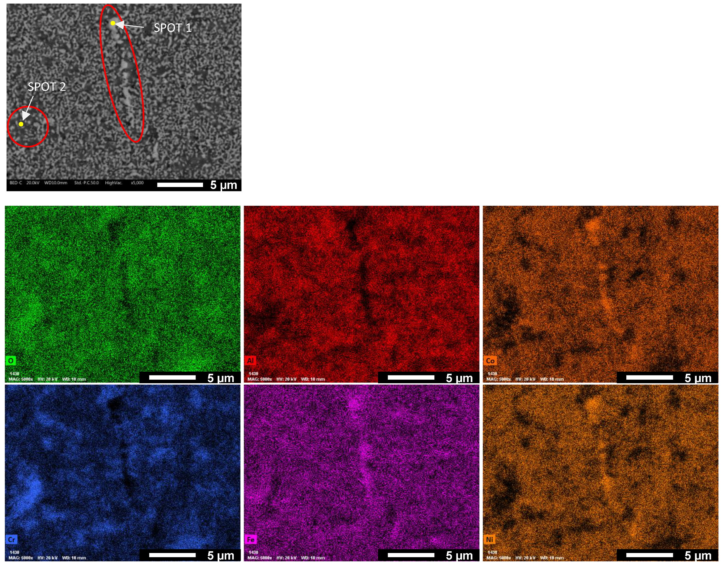
| SPOT 1 | 1.04 | 2.94 | 30.16 | 10.00 | 26.67 | 29.19 |
| SPOT 2 | 7.63 | 7.67 | 15.18 | 28.66 | 27.56 | 13.29 |
| Phase/Constituent | Co0.50_1200C | Co0.75_1200C | Co1.00_1250C | |
|---|---|---|---|---|
| Rwp (weighted profile R-factor) | 0.2838 | 0.2708 | 0.2593 | |
| FCC | Weight fraction % | 49.70% | 52.61% | 21.13% |
| Domain size [Å] | 179 | 192 | 196 | |
| Lattice strain (r.m.s.) | 2.97 × 10⁻³ | 2.96 × 10⁻³ | 2.90 × 10⁻³ | |
| Cell a [Å] | 3.600 | 3.598 | 3.579 | |
| Spinel | Weight fraction % | 41.22% | 28.99% | 10.06% |
| Domain size [Å] | 261 | 280 | 214 | |
| Cell a [Å] | 8.215 | 8.228 | 8.324 | |
| Al2O3 | Weight fraction % | 9.07% | 18.39% | 68.81% |
| Domain size [Å] | 595 | 466 | 277 | |
| Cell a [Å] | 4.780 | 4.781 | 4.868 | |
| Cell c [Å] | 13.033 | 13.035 | 13.279 |
| Kp (g2·cm−4·s−1) | |
|---|---|
| Co 1 | 26.83 × 10⁻¹² |
| Co 0.75 | 17.82 × 10⁻¹² |
| Co 0.50 | 7.43 × 10⁻¹² |
Disclaimer/Publisher’s Note: The statements, opinions and data contained in all publications are solely those of the individual author(s) and contributor(s) and not of MDPI and/or the editor(s). MDPI and/or the editor(s) disclaim responsibility for any injury to people or property resulting from any ideas, methods, instructions or products referred to in the content. |
© 2024 by the authors. Licensee MDPI, Basel, Switzerland. This article is an open access article distributed under the terms and conditions of the Creative Commons Attribution (CC BY) license (https://creativecommons.org/licenses/by/4.0/).
Share and Cite
Shaik, K.N.R.; Bortolotti, M.; Leizaola, I.; Lagos Gomez, M.A.; Menapace, C. Production and Characterization of Fine-Grained Multielement AlCoxCrFeNi (x = 1, 0.75, 0.5) Alloys for High-Temperature Applications. Materials 2024, 17, 4897. https://doi.org/10.3390/ma17194897
Shaik KNR, Bortolotti M, Leizaola I, Lagos Gomez MA, Menapace C. Production and Characterization of Fine-Grained Multielement AlCoxCrFeNi (x = 1, 0.75, 0.5) Alloys for High-Temperature Applications. Materials. 2024; 17(19):4897. https://doi.org/10.3390/ma17194897
Chicago/Turabian StyleShaik, Khaja Naib Rasool, Mauro Bortolotti, Iñaki Leizaola, Miguel Angel Lagos Gomez, and Cinzia Menapace. 2024. "Production and Characterization of Fine-Grained Multielement AlCoxCrFeNi (x = 1, 0.75, 0.5) Alloys for High-Temperature Applications" Materials 17, no. 19: 4897. https://doi.org/10.3390/ma17194897