Abstract
This study investigated changes in the crystal lattice, tribological properties and friction mechanism of AISI 316 steel irradiated with swift 160 MeV xenon ions. The irradiation process caused the increased roughness of the steel surface and the swelling of the material. The thickness of the irradiated layer increased by about 13 nm. Following irradiation with the fluences 2.5 × 10¹⁴ and 3.2 × 10¹⁴ (Xe24+/cm2), martensite formed in the surface layer. Fluctuating changes were also observed with respect to the coefficient of friction and the degree of wear of the AISI 316 steel samples. Irradiation also increased the microhardness of the steel.
1. Introduction
AISI 316 austenitic steel is widely used as a structural material in the food and chemical industries. It is also used for the construction of nuclear reactors and devices operating in high-radiation areas [1,2,3,4,5,6]. The interaction of low-energy ions of elements such as nitrogen, carbon or iron, for example, very often has a positive effect on the mechanical properties of metal alloys by increasing their resistance to corrosion [1,2], microhardness [3], cavitation erosion [4] or tribological wear [5,6,7]. For this reason, ion implantation is used in many industrial solutions as a method to increase the reliability of machines and equipment [8,9]. However, the interaction of highly-energetic particles leads to significant changes in material structure [10,11,12]. Therefore, research into the effects of high-energy particles on the structure and mechanical properties of AISI 316 steel becomes necessary.
The irradiation of AISI 316 with 2 MeV protons at 360 °C causes radiation-induced segregation of its components and radiation hardening [13]. A study [14] investigated the effect of irradiating austenitic steel at temperatures of 200, 300 and 400 (°C) with 8 MeV iron ions on its microstructure and hardness. The results showed a segregation of steel components at grain boundaries and an increase in the evolution of radiation defects with an increase in the irradiation temperature. It was also found that the nanohardness of the steel decreased with an increase in the irradiation temperature. Irradiation with 160 keV iron ions causes an increase in the grain (crystallite) size of AISI 316 [15]. Swelling is widely observed in austenitic steels irradiated with high doses at high temperatures [16]. A study [17] investigated the crystal lattice and defects formed in cold-worked austenitic stainless steel (CW 316 SS) irradiated with 7 MeV Xe26+ ions. Shifts in XRD diffraction peaks were observed, indicating an increase in the lattice constant. A study [18] investigated the radiation defects formed in austenitic steel AISI 316 as a result of irradiation at 360 °C with 2 MeV protons to doses up to 6.0 displacements per atom (dpa). The defects induced by proton irradiation included Frank loops, network dislocations, voids and nanotwins. Both the size and the density of the defects increased with the dose.
An analysis of the current state of research indicates that the effects of high-energy ions on the properties of AISI 316 steel are not yet fully understood. In this study, we focused on investigating the impact of xenon ion irradiation on the crystal lattice parameters, tribological properties, microhardness and swelling of AISI 316 grade steel. Our research specifically examined the global effects of irradiation-induced defects on these properties rather than the detailed characterization of the defects themselves.
Furthermore, the influence of varying irradiation doses on the friction and wear mechanisms was explored. The relationship between changes in the crystal lattice structure and tribological properties is well established. For instance, a correlation between the friction coefficient of a Ni monocrystal and its orientation relative to the countersample was reported in [19]. Similarly, for 100Cr6 steel [20] and titanium [21] samples irradiated with 160 MeV xenon ions, fluctuations in the friction coefficient and wear degree were observed to occur in tandem with changes in lattice parameters.
2. Materials and Methods
AISI 316 steel, whose chemical composition is given in Table 1, was prepared by Goodfellow Cambridge Ltd. (Huntingdon, UK). Several sets of samples were cut out from AISI 316 and polished. Each set of samples was polished mechanically under the same conditions using a MECATECH 250 SPI polishing machine (Presi, Eybens, France). The surface of the specimens was ground using abrasive papers with gradations from 180 to 600 µm and then polished using 9 µm and 0.3 µm diamond slurries. A mirror-like surface quality was obtained. Some of the samples were annealed in order to remove defects formed during the manufacture of the steel and the preparation of the samples. The chemical composition of this steel grade and that of the countersample (100Cr6) are given in Table 1.

Table 1.
Chemical composition of steel grades of AISI 316 (sample) and 100Cr6 (countersample).
Four sets of samples were prepared from annealed and unannealed steel. The samples were irradiated with 160 MeV xenon ions in swift heavy ion accelerator IC-100. To ensure uniform irradiation of the samples, the ion beam was swept over their surfaces both horizontally and vertically. The irradiation temperature did not exceed 60 °C, and the pressure in the chamber was below 1.1 × 10⁻⁹ Pa. The unannealed samples were irradiated with the following fluences: 1 × 10¹⁴, 2.5 × 10¹⁴ and 3.2 × 10¹⁴. The annealing samples were irradiated with the fluences 5 × 10¹⁴ Xe24+/cm2. Images of the steel surface were captured by atomic force microscopy (AFM) using Nanosurf Easyscan 2 (Nanosurf AG, Liestal, Switzerland). The samples were measured in air. The microscope was installed on active anti-vibration table TS-150. The atomic force microscope cantilevers were calibrated using the Sader method [22]. AFM images of the irradiated layer were processed using WSXM software (WSxM 5.0 Develop 10.3) [23] while the scanning electron microscope (SEM) utilized for this study was the TESCAN Vega 3LMU (Tescan Group, a.s., Brno–Kohoutovice, Czech Republic) equipped with the AZtecEnergy advanced EDX microanalyzer from Oxford Instruments (High Wycombe, UK). The EDX microanalyzer was calibrated using a MAC Universal 55 Reference Standard for X-ray microanalysis. This calibration allowed for element detectability at a level of 0.1% by weight, with measurement uncertainty ranging from 0.01% to 0.09% by weight. For SEM imaging, a backscattered electron detector (BSE) was used.
The coefficient of friction and the degree of wear were measured during tribological tests conducted under technically dry friction conditions with the Anton Paar NTR2 tribometer (CFM Instrument) (Anton Paar GmbH, Graz, Austria). The tests were conducted in compliance with the ASTM G99-17 Standard Test Method for Wear Testing with a Pin-on-Disk Apparatus [24]. The countersample was a ball made of 100Cr6 bearing steel (Table 1) with a diameter of 1 mm. The load applied in the tests was 300 mN. The speed of the countersample relative to that of the sample was 5.6 to 6.9 (cm/sec). Wear products were not removed from the friction zone. The degree of wear was measured based on the cross-sectional area of the track made by the countersample. The wear track was measured with the Intra Form Talysurf profilometer (Taylor Hobson Ltd., Leicester, UK) and then processed using Talymap Lite V7 software (ver. 7.4.9431, 2020/10/27). Using die fitted to the irregular shape of the profilograms, the degree of wear was calculated from 15 measurements (profilograms) obtained for each sample at different locations on the track circumference. Microhardness was measured in accordance with ASTM E384-22 [25], with a microhardness meter FM-800 from Future-Tech (Kawasaki, Japan) using the Vickers method with loads of 0.25 N, 1.96 N and 2.94 N. For the Vickers hardness test, the indenter has pyramidal sides with a square base shape with apex angle of θ equal to 136°. In all tests, the loading time was fixed at 10 s. Fifteen impressions were made for each load on each of the test specimens at different depths from the surface of the specimen. The crystal lattice was examined using the Empyrean diffractometer provided with the PIXcel 1D (Malvern Panalytical Ltd., Malvern, UK) silicon strip detector containing 255 strips and covering a range of 3.5° in 2θ scale. This data acquisition system enables fast measurements with high-quality statistics.
3. Results and Discussion
3.1. Irradiation of AISI 316 Samples
Theoretical calculations of the depth distribution of xenon ions and irradiation-induced defects were made using SRIM software (ver. SRIM 2013) [26]—Figure 1. The projected range Rp of xenon ions was 8.1 µm. It was assumed that the distribution of radiation defects was reflected by the distribution of vacancies produced during irradiation. The energy required to produce vacancies comes from the energy introduced into the target by xenon ions. Xenon ions were stopped due to the inelastic collisions with the target electrons (Se) and the elastic collisions with the nuclei of the target atoms (Sn). The magnitude of energy transferred into the target during the electronic (Se) and nuclear (Sn) stopping of xenon ions is shown in Figure 2.
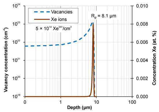
Figure 1.
Concentrations of xenon ions and defects induced in AISI 316 by irradiation with a fluence of 5 × 10¹⁴ Xe24+/cm2.
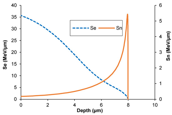
Figure 2.
Energy loss of xenon ions during electronic stopping Se and nuclear stopping Sn in AISI 316.
The interaction of ions with the target is conveniently described by means of displacement per atom (dpa) units which contain information about the ion fluence and energy as well as the binding energy of the atoms in the target. The dpa number specifies the number of possible displacements of a single atom during bombardment of the target—Figure 3. It does not take into account defect annealing and radiation-accelerated diffusion occurring at room temperature [27,28].
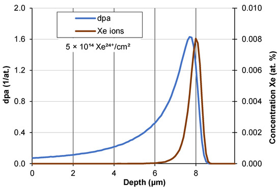
Figure 3.
Displacement per atom (dpa) of AISI 316 steel irradiated by xenon ions with a fluence of 5 × 10¹⁴ Xe24+/cm2.
3.2. Surface Topography of AISI 316
The surface of AISI 316 steel before and after irradiation was examined by AFM. One of the profiles is shown in Figure 4. Before irradiation, small irregularities can be seen on the surface, which was obtained after mechanical polishing. After irradiation with a maximum fluence of 5 × 10¹⁴ Xe24+/cm2, a number of bands about 10 nm high can be seen. These were formed by the sputtering of part of the surface layer located in between. The sputtering of the target components occurs during elastic collisions of xenon ions with the nuclei of the atoms forming the target. The sputtering rate depends on a number of factors [29,30]: the type of ions, their mass, charge and energy, the relative content of the target components, its crystallographic structure, the orientation of the grains relative to the ion beam, the surface roughness and the radiation-induced surface diffusion.
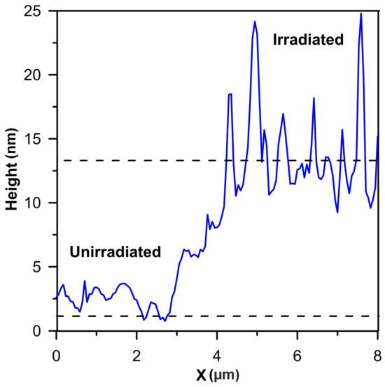
Figure 4.
Swelling height of AISI 316 irradiated by xenon ions with a fluence of 5 × 10¹⁴ Xe24+/cm2.
Irradiation also causes swelling of the sample. The increase in sample thickness is the result of a lattice constant effect, an increase in the number of lattice sites due to diffusion of displaced bulk atoms to the surface and a reduction due to sputtering. After irradiation with xenon ions of 160 MeV energy with a fluence of 5 × 10¹⁴ Xe24+/cm2 (1.6 dpa) at T ≤ 60 °C, the swelling height of AISI 316 steel is about 13 nm—Figure 4. In the work [31] AISI 316L steel irradiated at T 350° C with ions of 5 MeV energy with a fluence of 2.6 × 10¹⁵ ions/cm2 (3.7 dpa) had a swelling height of 11 nm. The swelling of AISI 316 steel, despite the high dpa = 3.7, is less than expected due to thermal annealing of some of the defects during irradiation. There is no linear relationship between dpa and the amount of swelling in the sample. Qualitatively, this can be explained within the framework of the multistep damage accumulation model [32,33,34]. In addition, ion-induced annealing may occur [35].
3.3. GXRD Measurements
The grazing incidence X-Ray diffraction (GXRD) method allows the crystalline structure of surface layers of a certain thickness to be studied by varying the angle of incidence (Θ) of X-rays—Figure 5. GXRD measurements were made using a copper lamp with a post-monochromatization X-ray wavelength of 0.1540598 nm.

Figure 5.
Illustration of the method of testing the crystalline structure of surface layers by GXRD: Q1 and Q2—angles of incidence of X-rays (X) on the sample surface, s—path length of X-rays in the sample material, which does not depend on the angle of incidence, and d1 and d2—depth from which scattered X-rays (X′) are emitted.
Prior to the irradiation of the unannealed sample, a pure austenitic structure (γ) is visible—Figure 6. Characteristic peaks corresponding to the martensitic phase γ (111), γ (200) and γ (220) can be seen, indicating its presence in the irradiated structure. The noticeable changes in peak intensity at different incident angles may suggest some variation in defect distribution and phase transformation as a function of depth. In contrast, the irradiation process of unannealed samples performed with the fluences 2.5 × 10¹⁴ Xe24+/cm2 and 3.2 × 10¹⁴ Xe24+/cm2, which results in the formation of martensite (α) amounting to about 1.5%. The formation of martensite was observed in a study [36] where the specimens were subjected to solution treatment at 1050 °C for 6 min followed by the water cooling to room temperature. A study [37] also described the transformation of original austenite into martensite in AISI 316L steel subjected to severe shot peening (SSP). There is no martensitic phase in the unheated steel unirradiated and irradiated with a minimum fluence of 1.0 × 10¹⁴ Xe24+/cm2. This phase is also absent in the heated steel after irradiation with a maximum fluence of 5.0 × 10¹⁴ Xe24+/cm2—Figure 6. This means that the transformation of part of the austenitic phase into a martensitic phase occurs after irradiation with 2.5–3.2 × 10¹⁴ Xe24+/cm2 and does not depend on the thermal treatment of the sample before irradiation.
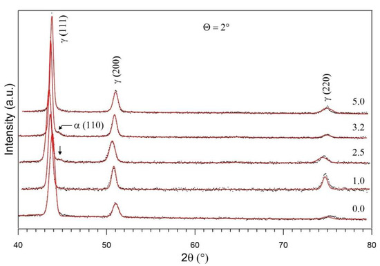
Figure 6.
GXRD spectrum measured at Θ = 2°, unirradiated and irradiated by 160 MeV xenon ions with fluences: 1.0, 2.5, 3.2 and 5.0 (×1014 Xe24+/cm2).
After irradiation of the unannealed samples with a fluence of 3.2 × 10¹⁴ Xe²⁴⁺/cm², X-ray diffractograms measured at different incident angles (0.5°, 1°, 2° and 4°) show the presence of a martensitic phase throughout the irradiated layer of AISI 316 steel—Figure 7. Characteristic peaks corresponding to the martensitic phase γ (111), γ (200) and γ (220) can be seen, indicating its presence in the irradiated structure. The noticeable changes in peak intensity at different incident angles may suggest some variation in defect distribution and phase transformation as a function of depth.
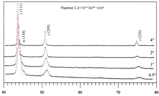
Figure 7.
GXRD spectrum measured at Θ = 0.5°, 1°, 2° and 4°, irradiated by 160 MeV xenon ions with fluence 3.2 × 10¹⁴ Xe24+/cm2.
Fluctuating changes in the position of the GXRD spectrum peaks of austenite (111), (200) and (220) occur in the same phase with changes of the irradiation fluence—Figure 6. This means that the lattice constant changes with the increase of the irradiation fluence (Table 2). The changes in the lattice constant of layers located at different depths, depending on the incident angle Θ and irradiation fluence, are given in Table 2. The most pronounced changes were observed for the samples irradiated with a fluence of 2.5 × 10¹⁴ Xe24+/cm2 for all incident angles. Irradiation with fluences of 1 and 2.5 × 10¹⁴ (Xe24+/cm2) led to a greater increase in the lattice constant than irradiation with higher fluences.

Table 2.
Changes in the lattice constant Δa (nm) for different irradiation fluences and incident angles versus unirradiated bulk sample; d—thickness (depth) of tested layer.
A small increase in the lattice constant can be observed after high fluence irradiation. The lack of a linear relationship between irradiation fluence and changes in the lattice constant may be due to the gradual accumulation of defects and their evolution after reaching a characteristic density [32,33,34]. The lack of such a relationship may be partly attributable to partial quenching of defects during irradiation with a higher ion fluence [35]. The subsequent ion portion may partially rebuild radiation damage caused during the previous irradiation step.
The range of X-rays in a given target depends on their energy and the absorption capacity of the target. By changing the incident angle, we can change the depth from which the signal reaches the detector.
3.4. Coefficient of Friction and Wear of Steel
The results of the coefficient of friction from the tribological tests are shown in Figure 8. The lowest coefficient of friction was obtained for the unannealed and unirradiated steel samples, i.e., those with only defects formed during standard sample preparation—cutting, grinding and polishing. The coefficient of friction for the unannealed and unirradiated samples becomes stable at 0.35 above 2000 measurement cycles. Following irradiation with fluences of 1, 2.5 and 3.2 (×1014 Xe24+/cm2), there is a significant increase in the coefficient of friction value. The changes are fluctuating and depend on the irradiation dose. The largest fluctuations in the coefficient of friction during the tribological test are observed for the steel irradiated with a fluence of 2.5 × 10¹⁴ Xe24+/cm2. Irradiation with this fluence value maximally increases the lattice constant in all the tested layers (at different depths)—Table 3. The observed increase in the coefficient of friction for the AISI 316 steel specimens irradiated with high-energy xenon ions is similar to the exposure to the same Xe ion radiation of 100Cr6 bearing steel [20]. The increase in the coefficient of friction of the irradiated samples is often attributed to an increase in stresses in the surface layer and increased surface roughness caused by the impact of large and fast xenon particles.
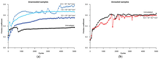
Figure 8.
Changes in the coefficient of friction for the AISI 316 samples during tribological testing for (a) unannealed samples and (b) annealed samples [38].

Table 3.
Changes in the microhardness of the AISI 316 steel samples after irradiation.
The annealed samples have a relatively high coefficient of friction, with its value becoming stable at 0.6 above 2000 measurement cycles. Irradiating the samples with a 5 × 10¹⁴ Xe24+/cm2 fluence causes high fluctuations in the coefficient of friction during tribological tests. The defects produced during mechanical sample preparation significantly reduce the friction coefficient—Figure 8a, compared to annealed samples—Figure 8b. Radiation defects created after irradiation increase the friction coefficient of the material as compared to the non-irradiated material. The friction coefficient of the annealed samples after irradiation with a fluence of 5 × 10¹⁴ Xe24+/cm2 shows large local changes—Figure 8b.
After a 5000-cycle tribological test, profilometric measurements of the wear track on the sample were conducted, and based on these measurements, the average wear for each sample was determined. The results are presented in Figure 9. The lowest wear is obtained for the unirradiated AISI 316 samples after annealing. The use of irradiation does not change the degree of wear of the annealed samples, just as it did not change the coefficient of friction above 2000 measurement cycles—Figure 8a.
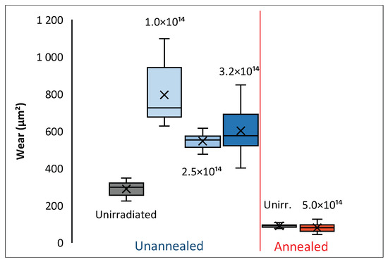
Figure 9.
Wear of samples after 5000 measurement cycles of a tribological test.
3.5. SEM Images of Countersamples
SEM images of the wear track on a 100Cr6 steel countersample interacting with the unannealed AISI 316 steel samples during the tribological test are shown in Figure 10. On the countersample surface, the presence of abraded fragments can be observed from both the unirradiated sample (Figure 10a) and the sample irradiated with a 1 × 10¹⁴ Xe24+/cm2 fluence (Figure 10b). These abraded fragments remain on the countersample’s surface during the test and are pressed against it, leading to further wear of the sample. The presence of wear products near the wear track may be facilitated by weak magnetic interactions of the abraded fragments with the countersample. A study [39] showed that defects in SiC material fragments could induce magnetic interaction. Irradiation with a higher fluence leads to increased microhardness and abrasive wear of the sample. The SEM images in Figure 10c and partially in Figure 10d shows characteristic stripes on the surface of the countersamples that were abraded by the samples with increased microhardness, which is confirmed by the microhardness measurement data of the samples described later in this paper.
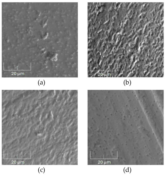
Figure 10.
SEM images of the wear track on the surface of the 100Cr6 countersamples after tribological testing of the unannealed AISI 316 steel samples: (a) unirradiated, (b) irradiated with a fluence of 1 × 10¹⁴ Xe24+/cm2, (c) 2.5 × 10¹⁴ Xe24+/cm2 and (d) 3.2 × 10¹⁴ Xe24+/cm2. Magnification: 5000×.
Figure 11 shows SEM images of the wear track on the surface of the countersamples after tribological tests conducted on the annealed AISI 316 steel samples. Figure 11a shows small fragments of the annealed unirradiated sample deposited on the surface of the counterexample. Small holes from the chipped counterexample material can also be seen. After irradiation with a 5 × 10¹⁴ Xe24+/cm2 fluence, the microhardness of the annealed AISI 316 steel increases, carving characteristic stripes on the surface of the counterexample during the tribology test. This observation is confirmed by the data in Table 3.
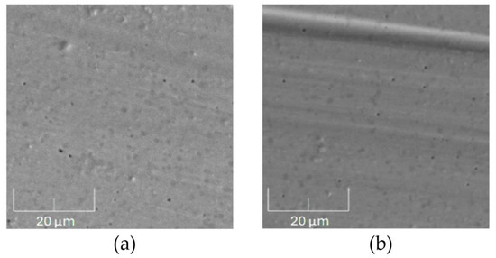
Figure 11.
SEM images of the wear track on a 100Cr6 countersample after tribological tests conducted on annealed the AISI 316 samples: (a) unirradiated and (b) irradiated with a fluence of 5 × 10¹⁴ Xe24+/cm2. Magnification: 5000×.
3.6. Microhardness
Microhardness tests on AISI 316 steel measured at different loads before and after implantation of Xe24+ ions showed clear changes that can be attributed to both direct implantation effects and the changes in the material’s crystalline structure found earlier. These results, illustrated in Table 3 and Figure 12, show different changes depending on the indenter load (0.25 N, 1.96 N and 2.94 N).
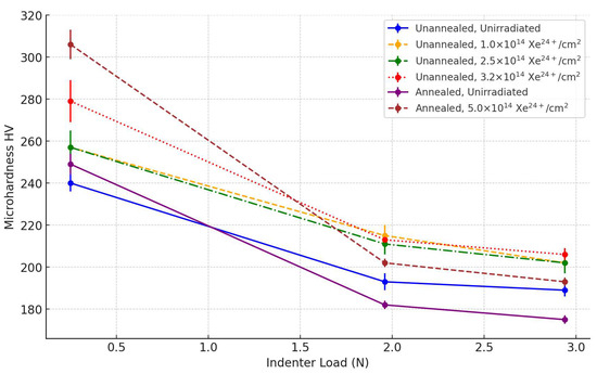
Figure 12.
Average microhardness values of tested AISI 316 steel specimens at different indenter loads.
Microhardness measurements performed with a load of 0.25 N, where the indentation depth did not exceed 3 µm, showed that the implantation of Xe ions caused a significant increase in microhardness. For the non-annealed samples, the microhardness value increased from 240 HV to 279 HV, with a highest fluence of 3.2 × 10¹⁴ Xe24+/cm2. A similar increase was observed in the annealed samples, where the hardness reached 306 HV after implantation at a fluence of 5 × 10¹⁴ Xe24+/cm2. This significant change in surface hardness can be directly related to the structural changes found in the GXRD tests. The formation of martensite in this zone, which is a harder phase than the original austenite, contributes to the increased resistance to plastic deformation, leading to an increase in microhardness. In addition, changes in the crystal lattice constant and fluctuations in the austenite peaks (111), (200) and (220) suggest the existence of significant lattice stresses, which can also strengthen the surface layer of the material.
Measurements made with a load of 1.96 N indicate that the imprint depth of the irradiated samples does not exceed 8.5 μm. At this depth, according to SRIM simulation results, the maximum concentration of implanted ions and defects is located. Also, for these measurement parameters, a significant increase in microhardness was observed compared to samples without implantation. In the unannealed samples, the microhardness increased from 193 HV to 213 HV at a fluence of 3.2 × 10¹⁴ Xe24+/cm2. In the annealed samples, the value increased from 182 HV to 202 HV after implantation with a fluence of 5 × 10¹⁴ Xe24+/cm2.
These changes are consistent with observations of an increase in crystallite size and a reduction in crystal lattice deformation at this depth, as demonstrated by GXRD. The formation of defects in this zone, including vacancies and atomic clustering, contributes to the strengthening of the material by reducing dislocation mobility, which in turn increases microhardness. Furthermore, the observed changes in the crystal lattice constant may affect the local stress concentration, which further contributes to the increase in hardness at this depth. A similar phenomenon of an increase in microhardness at the depth corresponding to the highest ion concentration was found in certain works [40,41]. An increase in the microhardness of AISI 316L steel beyond the range of high-energy protons can be seen in Figure 7 of the paper [13].
At the highest applied indenter load (2.94 N), the indenter was observed to penetrate to a depth of 10.5–10.6 um for unirradiated samples that had been irradiated with Xe ions. The irradiated and previously annealed sample showed a depression of approximately 10.8 um. These are above the original range of Xe ions. Changes in microhardness at a depth of 10 µm are less pronounced, indicating that the effect of irradiation on the deeper layers of the material is limited and may be due to the influence of the surface layer during microhardness measurement. A similar increase in the nanohardness of 2 MeV proton-irradiated AISI 316 steel was also observed in [13] at a depth greater than the implanted ion range calculated with the SRIM package [26].
3.7. EDX Measurements
SEM images of the wear track on the annealed samples during the tribological test are shown in Figure 13. The line drawn in the figure represents a scanning path along which the contents of oxygen, carbon, iron and chromium were measured. Oxygen and carbon are elements that can significantly influence the friction process, while iron and chromium are the main components of steel. In the annealed samples, reduced abrasion resistance is evident, as shown in Figure 13a. Large sections of the sample material are pulled out, indicating the presence of adhesive and abrasive wear accompanied by oxidative wear. This is consistent with the increased oxygen content detected along the wear track, suggesting the formation of surface oxides that exacerbate material degradation.
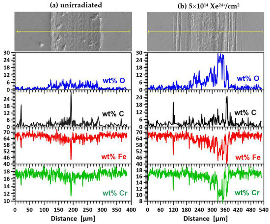
Figure 13.
Images of the surface and wear track of the annealed steel AISI 316 samples with a scan line for elemental mapping: (a) unirradiated and (b) irradiated with a fluence of 5 × 10¹⁴ Xe24+/cm2.
The irradiation process significantly alters the wear track morphology, as shown in Figure 13b. Grooves, mounds and small clusters of displaced material are visible, pointing to a more complex wear mechanism. The increased oxidative wear is likely due to enhanced oxygen diffusion along radiation-induced defects, allowing oxygen to penetrate deeper into the sample and promote oxidation. This phenomenon can be attributed to the high fluence of xenon ions, which created diffusion pathways for oxygen through radiation-induced defects. Radiation significantly influences oxygen diffusion in materials, particularly steel, by increasing point defect concentrations and enhancing diffusion pathways [42,43,44]. Irradiation of heated samples alters the friction process. Adhesive wear decreases, and oxidative wear increases. It is interesting to note that the amount of grated material does not change during the tribological test.
EDX analysis revealed the presence of carbon on the surface of samples—Figure 13 and Figure 14. This originated from residual oil vapour deposited during EDX measurements despite the turbomolecular pumps used to minimize contamination of the sample surfaces. In contrast, the carbon at the bottom of trace—Figure 14d (an unheated sample irradiated with a fluence of 3.2 × 10¹⁴ Xe24+/cm2) was transferred from the 100Cr6 pre-sample due to chemical reactions with Fe, Co and Ni to form carbides of these metals. These reactions were favoured by the high temperature, as evidenced by the melting of the surface of the counterexamples during the tribological test. This is particularly evident in Figure 10b,c. The surface of the samples was also remelted—see the SEM microphotograph in Figure 14d. Several depressions can be seen on the surface of the trace, indicating local suturing of the sample and countersample fragments. In addition, the friction coefficient of the unheated sample after irradiation with a flux of 3.2 × 10¹⁴ Xe24+/cm2 is the lowest among the irradiated samples and has a rather smooth course—Figure 8a. The presence of carbon can cause a reduction in the friction coefficient. Its implantation has long been used to improve the tribological properties of steels [45].
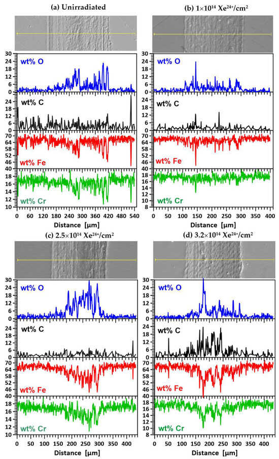
Figure 14.
Images of the surface of the unannealed AISI 316 samples together with a scan line for elemental mapping before irradiation (a) and after irradiation with fluences: (b) 1 × 10¹⁴ Xe24+/cm2, (c) 2.5 × 10¹⁴ Xe24+/cm2 and (d) 3.2 × 10¹⁴ Xe24+/cm2.
Figure 14a–d show SEM images of the wear track on the unannealed samples during the tribological test and the results of oxygen (O), carbon (C), iron (Fe) and chromium (Cr) measurements along the wear track. For the unirradiated specimens (Figure 14a) and those irradiated with doses of 1 × 10¹⁴ Xe24+/cm2 (Figure 14b) and 2.5 × 10¹⁴ Xe24+/cm2 (Figure 14c), the wear mechanism did not change significantly compared to the unirradiated specimen. EDX analysis showed no significant differences in the elemental content of the wear trace. Wear was still of an oxidative, abrasive and adhesive nature, as in the unimplanted sample.
Only implantation with a dose of 3.2 × 10¹⁴ Xe24+/cm2 (Figure 14d) caused significant changes in the wear mechanism. SEM microphotography shows an increase in adhesive wear and remelting of the sample surface. Adhesive wear is confirmed by an increase in the carbon content of the wiped trace on the sample surface, which originates from the countersample.
4. Conclusions
The irradiation of AISI 316 steel with 160 MeV xenon ions causes an increase in surface roughness, an increase swelling, an increase in the lattice constant value and changes in the mechanical properties of the modified layer. The surface roughness increase is due to different sputtering rates of the steel components. The changes in the surface condition induced by irradiation with a 5 × 10¹⁴ Xe24+/cm2 fluence can be seen in the AFM image—Figure 3. Irradiation increases the thickness of the modified layer by 13 nm. These changes result from an increase in the lattice constant and an increase in the number of lattice sites due to diffusion of displaced bulk atoms to the surface and a reduction due to sputtering.
The lattice constant decreases with an increase in the irradiation fluence. A similar effect was reported in a study [11]. The displacement of the γ peak (111) toward smaller angles 2θ in the irradiated CW316SS steel decreases after irradiation with the maximum fluence. The smaller increase in the lattice constant after higher fluence irradiation may be due to the annealing of some radiation defects produced during the nuclear and electronic stopping of xenon ions. During irradiation with a 5 × 10¹⁴ Xe24+/cm2 fluence, a single atom of AISI 316 located at a depth of 7.8 μm theoretically can statistically change its lattice site an average of 1.6 times.
The coefficient of friction and the degree of wear of the AISI 316 steel samples depend on a number of factors: the lattice constant value, microhardness and the interaction of the countersample with the sample. The maximum increase in the lattice constant after irradiation with a fluence of 2.5 × 10¹⁴ Xe24+/cm2 is correlated with the maximum coefficient of friction and the maximum fluctuations in the coefficient of friction during the tribological test.
Implantation of Xe24+ ions with an energy of 160 MeV leads to significant changes in the microhardness of AISI 316 steel, with the greatest changes observed at relatively low loads at depths corresponding to the maximum concentration of implanted ions and structural defects (3 µm and 8 µm). The increase in hardness is closely related to changes in the structure of the crystal lattice, including the formation of martensite, an increase in crystallite size and a reduction in lattice stresses, as demonstrated by GXRD studies. Changes in microhardness at a depth of 10 µm are less pronounced, indicating that the effect of implantation on the deeper layers of the material is limited. They can be caused by the influence of the surface layer when measuring microhardness.
Changes in tribological properties induced by irradiation depend on several factors: surface topography, crystal lattice constant and lattice strain, crystallite size, microhardness and the interaction of the AISI 316 steel components with the countersample material. The combined effect of these factors leads to fluctuations in tribological changes depending on irradiation fluence.
Author Contributions
Conceptualization, P.B. and M.K.; methodology, P.B. and M.K.; formal analysis, P.B. and M.K.; investigation, M.K., M.W. and Z.S.; data analysis, M.K., P.B., M.W. and Z.S.; writing—original draft preparation, P.B. and M.K.; writing—review and editing, M.K. and P.B.; visualization, P.B. and M.K.; supervision, P.B. All authors have read and agreed to the published version of the manuscript.
Funding
This research received no external funding.
Institutional Review Board Statement
Not applicable.
Informed Consent Statement
Not applicable.
Data Availability Statement
The data presented in this study are available on request from the corresponding author.
Acknowledgments
The authors would like to express their sincerest thanks to V.A. Skuratov for irradiating the samples.
Conflicts of Interest
The authors declare no conflicts of interest.
References
- Picard, S.; Memet, J.B.; Sabot, R.; Grosseau-Poussard, J.L.; Rivière, J.P.; Meilland, R. Corrosion Behaviour, Microhardness and Surface Characterisation of Low Energy, High Current Ion Implanted Austenitic Stainless Steel. Mater. Sci. Eng. A 2001, 303, 163–172. [Google Scholar] [CrossRef]
- Wang, F.; Zhou, C.; Zheng, L.; Zhang, H. Improvement of the Corrosion and Tribological Properties of CSS-42L Aerospace Bearing Steel Using Carbon Ion Implantation. Appl. Surf. Sci. 2017, 392, 305–311. [Google Scholar] [CrossRef]
- Budzyński, P.; Kamiński, M.; Pałka, K.; Droździel, A.; Wiertel, M. The Influence of Nitrogen Ion Implantation on Microhardness of the Stellite 6 Alloy. IOP Conf. Ser. Mater. Sci. Eng. 2016, 148, 012046. [Google Scholar] [CrossRef]
- Szala, M.; Chocyk, D.; Skic, A.; Kamiński, M.; Macek, W.; Turek, M. Effect of Nitrogen Ion Implantation on the Cavitation Erosion Resistance and Cobalt-Based Solid Solution Phase Transformations of HIPed Stellite 6. Materials 2021, 14, 2324. [Google Scholar] [CrossRef]
- Foerster, C.E.; da Silva, S.L.R.; Fitz, T.; Dekorsy, T.; Prokert, F.; Kreiβig, U.; Richter, E.; Möller, W.; Lepienski, C.M.; de M. Siqueira, C.J. Carbon Ion Implantation into Aluminium: Mechanical and Tribological Properties. Surf. Coat. Technol. 2006, 200, 5210–5219. [Google Scholar] [CrossRef]
- Saritas, S.; Procter, R.P.M.; Grant, W.A. The Use of Ion Implantation to Modify the Tribological Properties of Ti-6Al-4V Alloy. Mater. Sci. Eng. 1987, 90, 297–306. [Google Scholar] [CrossRef]
- Yan, S.; Zhao, W.J.; Rück, D.M.; Xue, J.M.; Wang, Y.G. Study of Tribological Properties of High-Speed Steel Implanted by High-Dose Carbon Ions. Surf. Coat. Technol. 1998, 103–104, 348–352. [Google Scholar] [CrossRef]
- Kaminski, M.; Budzynski, P.; Hunicz, J.; Jozwik, J. Evaluation of Changes in Fuel Delivery Rate by Electromagnetic injectors in a Common Rail System during Simulated Operation. Eksploat. I Niezawodn.-Maint. Reliab. 2021, 23, 352–358. [Google Scholar] [CrossRef]
- Dearnaley, G. Applications of Ion Implantation in Metals & Alloys. IEEE Trans. Nucl. Sci. 1981, 28, 1808–1811. [Google Scholar] [CrossRef]
- Kamiński, M.; Budzyński, P.; Surowiec, Z.; Wiertel, M.; Skuratov, V.A. Surface Morphology and Phase Stability of Titanium Irradiated with 168 MeV 136Xe Ions. Int. J. Mater. Res. 2018, 109, 779–784. [Google Scholar] [CrossRef]
- AL-Khoury, W.; Naddaf, M.; Ahmad, M. MeV-Fe Ions Implantation of GaAs—Induced Morphological and Structural Modification of Porous GaAs. Nucl. Instrum. Methods Phys. Res. B 2021, 492, 1–6. [Google Scholar] [CrossRef]
- Bosia, F.; Argiolas, N.; Bazzan, M.; Olivero, P.; Picollo, F.; Sordini, A.; Vannoni, M.; Vittone, E. Modification of the Structure of Diamond with MeV Ion Implantation. Diam. Relat. Mater. 2011, 20, 774–778. [Google Scholar] [CrossRef]
- Jin, H.H.; Hwang, S.S.; Choi, M.J.; Lee, G.G.; Kwon, J. Proton Irradiation for Radiation-Induced Changes in Microstructures and Mechanical Properties of Austenitic Stainless Steel. J. Nucl. Mater. 2019, 513, 271–281. [Google Scholar] [CrossRef]
- Jin, H.H.; Ko, E.; Lim, S.; Kwon, J.; Shin, C. Effect of Irradiation Temperature on Microstructural Changes in Self-Ion Irradiated Austenitic Stainless Steel. J. Nucl. Mater. 2017, 493, 239–245. [Google Scholar] [CrossRef]
- Radiguet, B.; Etienne, A.; Pareige, P.; Sauvage, X.; Valiev, R. Irradiation Behavior of Nanostructured 316 Austenitic Stainless Steel. J. Mater. Sci. 2008, 43, 7338–7343. [Google Scholar] [CrossRef]
- Hure, J.; Courcelle, A.; Turque, I. A Micromechanical Analysis of Swelling-Induced Embrittlement in Neutron-Irradiated Austenitic Stainless Steels. J. Nucl. Mater. 2022, 565, 153732. [Google Scholar] [CrossRef]
- Huang, H.F.; Li, J.J.; Li, D.H.; Liu, R.D.; Lei, G.H.; Huang, Q.; Yan, L. TEM, XRD and Nanoindentation Characterization of Xenon Ion Irradiation Damage in Austenitic Stainless Steels. J. Nucl. Mater. 2014, 454, 168–172. [Google Scholar] [CrossRef]
- Lim, Y.S.; Kim, D.J.; Choi, M.J.; Hwang, S.S.; Kim, S.W. Effects of the Dose and Depth on the Microstructural Characteristics of Proton-Irradiated Austenitic 316 Stainless Steel. Mater. Charact. 2022, 194, 112445. [Google Scholar] [CrossRef]
- Prasad, S.V.; Michael, J.R.; Battaile, C.C.; Majumdar, B.S.; Kotula, P.G. Tribology of Single Crystal Nickel: Interplay of Crystallography, Microstructural Evolution, and Friction. Wear 2020, 458–459, 203320. [Google Scholar] [CrossRef]
- Kamiński, M.; Budzyński, P.; Surowiec, Z.; Wiertel, M.; Zdorovets, M.V.; Kozlovskiy, A.; Waliszewski, J.; Magdziak, M. Effect of 160 MeV Xenon Ion Irradiation on the Tribological Properties and Crystal Structure of 100Cr6 Bearing Steel. Materials 2023, 16, 6660. [Google Scholar] [CrossRef]
- Budzyński, P.; Kamiński, M.; Surowiec, Z.; Wiertel, M.; Skuratov, V.A.; Korneeva, E.A. Effects of Xenon-Ion Irradiation on the Tribological Properties and Crystal Structure of Titanium and Its Alloy Ti6Al4V. Tribol. Int. 2021, 156, 106854. [Google Scholar] [CrossRef]
- Sader, J.E.; Chon, J.W.M.; Mulvaney, P. Calibration of Rectangular Atomic Force Microscope Cantilevers. Rev. Sci. Instrum. 1999, 70, 3967–3969. [Google Scholar] [CrossRef]
- Horcas, I.; Fernández, R.; Gómez-Rodríguez, J.M.; Colchero, J.; Gómez-Herrero, J.; Baro, A.M. WSXM: A Software for Scanning Probe Microscopy and a Tool for Nanotechnology. Rev. Sci. Instrum. 2007, 78, 013705. [Google Scholar] [CrossRef] [PubMed]
- ASTM G99-17; Standard Test Method for Wear Testing with a Pin-on-Disk Apparatus. ASTM International: West Conshohocken, PA, USA, 2017.
- ASTM E384-22; Standard Test Method for Microindentation Hardness of Materials. ASTM International: West Conshohocken, PA, USA, 2021.
- Ziegler, J.F.; Ziegler, M.D.; Biersack, J.P. SRIM—The Stopping and Range of Ions in Matter (2010). Nucl. Instrum. Methods Phys. Res. B 2010, 268, 1818–1823. [Google Scholar] [CrossRef]
- Oyarzabal, Í.M.; Tunes, M.A.; Camara, O.; Aradi, E.; Mir, A.H.; Greaves, G.; Hinks, J.A.; Fitchner, P.F.P.; Donnelly, S.E. The Effect of Flux on Ion Irradiation-Enhanced Precipitation in AISI-316L: An in-Situ TEM Study. J. Nucl. Mater. 2020, 541, 152414. [Google Scholar] [CrossRef]
- Was, G.S. Fundamentals of Radiation Materials Science: Metals and Alloys; Springer: New York, NY, USA, 2007; ISBN 978-3540494713. [Google Scholar]
- Behrisch, R.; Eckstein, W. Sputtering by Particle Bombardment: Experiments and Computer Calculations from Threshold to MeV Energies; Springer: Berlin/Heidelberg, Germany, 2007; ISBN 978-3-540-44500-2. [Google Scholar]
- Matsunami, N.; Yamamura, Y.; Itikawa, Y.; Itoh, N.; Kazumata, Y.; Miyagawa, S.; Morita, K.; Shimizu, R.; Tawara, H. Energy Dependence of the Ion-Induced Sputtering Yields of Monatomic Solids. At. Data Nucl. Data Tables 1984, 31, 1–80. [Google Scholar] [CrossRef]
- Lin, J.; Chen, F.; Tang, X.; Liu, J.; Shen, S.; Ge, G. Radiation-Induced Swelling and Hardening of 316L Stainless Steel Fabricated by Selected Laser Melting. Vacuum 2020, 174, 109183. [Google Scholar] [CrossRef]
- Jagielski, J.; Thomé, L. Multi-Step Mechanism of Damage Accumulation in Irradiated Crystals. Nucl. Instrum. Methods Phys. Res. B 2008, 266, 1212–1215. [Google Scholar] [CrossRef]
- Debelle, A.; Moll, S.; Décamps, B.; Declémy, A.; Thomé, L.; Sattonnay, G.; Garrido, F.; Jozwik, I.; Jagielski, J. Ability of Cubic Zirconia to Accommodate Radiation Damage. Scr. Mater. 2010, 63, 665–668. [Google Scholar] [CrossRef]
- Mieszczynski, C.; Ratajczak, R.; Jagielski, J.; Velişa, G.; Bei, H.; Sales, B.C.; Wendler, E.; Weber, W.J.; Zhang, Y. Defect Evolution in Ni and Solid-Solution Alloys of NiFe and NiFeCoCr under Ion Irradiation at 16 and 300 K. J. Nucl. Mater. 2020, 534, 152138. [Google Scholar] [CrossRef]
- Weber, W.J.; Duffy, D.M.; Thomé, L.; Zhang, Y. The Role of Electronic Energy Loss in Ion Beam Modification of Materials. Curr. Opin. Solid State Mater. Sci. 2015, 19, 1–11. [Google Scholar] [CrossRef]
- Song, R.B.; Xiang, J.Y.; Hou, D.P. Characteristics of Mechanical Properties and Microstructure for 316L Austenitic Stainless Steel. J. Iron Steel Res. Int. 2011, 18, 53–59. [Google Scholar] [CrossRef]
- Gundgire, T.; Jokiaho, T.; Santa-aho, S.; Rautio, T.; Järvenpää, A.; Vippola, M. Comparative Study of Additively Manufactured and Reference 316 L Stainless Steel Samples—Effect of Severe Shot Peening on Microstructure and Residual Stresses. Mater. Charact. 2022, 191, 112162. [Google Scholar] [CrossRef]
- Budzyński, P. Effect of Ion Irradiation on the Properties of Metals and Alloys, 1st ed.; Routledge: London, UK, 2024. [Google Scholar]
- Zhang, X.; Zhang, Z.; Akhmadaliev, S.; Zhou, S.; Wu, Y.; Guo, B. Structural and Magnetic Properties of Swift Heavy-Ion Irradiated SiC. Vacuum 2021, 184, 109849. [Google Scholar] [CrossRef]
- Dey, S.; Dutta, A.; Mukherjee, P.; Gayathri, N.; Gupta, A.D.; Roy, T.K. Characterization of Ion Induced Damage as a Function of Depth in Proton Irradiated Pure Ti and Ti–6Al–4V. J. Alloys Compd. 2020, 821, 153441. [Google Scholar] [CrossRef]
- Dai, L.Y.; Niu, G.Y.; Ma, M.Z. Microstructure Evolution and Nanotribological Properties of Different Heat-Treated AISI 420 Stainless Steels after Proton Irradiation. Materials 2019, 12, 1736. [Google Scholar] [CrossRef]
- Okubo, N.; Fujimura, Y.; Tomobe, M. Effect of Irradiation on Corrosion Behavior of 316L Steel in Lead-Bismuth Eutectic with Different Oxygen Concentrations. Quantum Beam Sci. 2021, 5, 27. [Google Scholar] [CrossRef]
- Sizmann, R. The Effect of Radiation upon Diffusion in Metals. J. Nucl. Mater. 1978, 69–70, 386–412. [Google Scholar] [CrossRef]
- Ye, Z.; Lei, Y.; Zhang, J.; Zhang, Y.; Li, X.; Xu, Y.; Wu, X.; Liu, C.S.; Hao, T.; Wang, Z. Effects of Oxygen Concentration and Irradiation Defects on the Oxidation Corrosion of Body-Centered-Cubic Iron Surfaces: A First-Principles Study. Chin. Phys. B 2022, 31, 86802. [Google Scholar] [CrossRef]
- Alonso, F.; García, A.; Ugarte, J.J.; Viviente, J.L.; Oñate, J.I.; Baranda, P.S.; Cooper, C.V. Changes in Tribological Properties of an AISI 440C Martensitic Stainless Steel after Ion Implantation of Carbon at Very High Doses. Surf. Coat. Technol. 1996, 83, 263–268. [Google Scholar] [CrossRef]
Disclaimer/Publisher’s Note: The statements, opinions and data contained in all publications are solely those of the individual author(s) and contributor(s) and not of MDPI and/or the editor(s). MDPI and/or the editor(s) disclaim responsibility for any injury to people or property resulting from any ideas, methods, instructions or products referred to in the content. |
© 2024 by the authors. Licensee MDPI, Basel, Switzerland. This article is an open access article distributed under the terms and conditions of the Creative Commons Attribution (CC BY) license (https://creativecommons.org/licenses/by/4.0/).