
Influence of Finishing Process Parameters of HDF Boards on Selected Properties of Coatings in Modern UV Lines and Their Relation to Energy Consumption


Abstract
1. Introduction
2. Materials and Methods
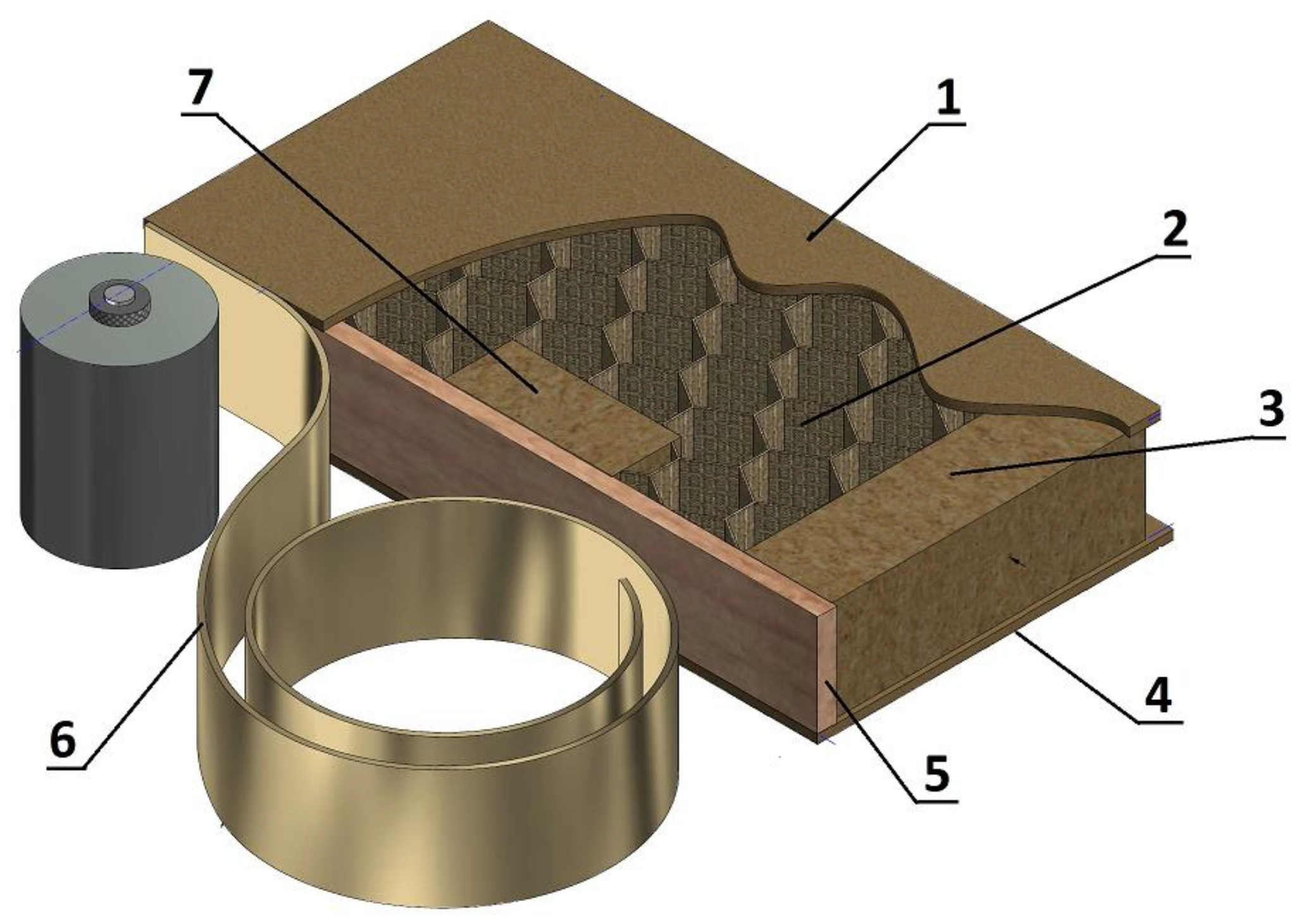
2.1. Substrate and Coating Products
2.2. Research Method
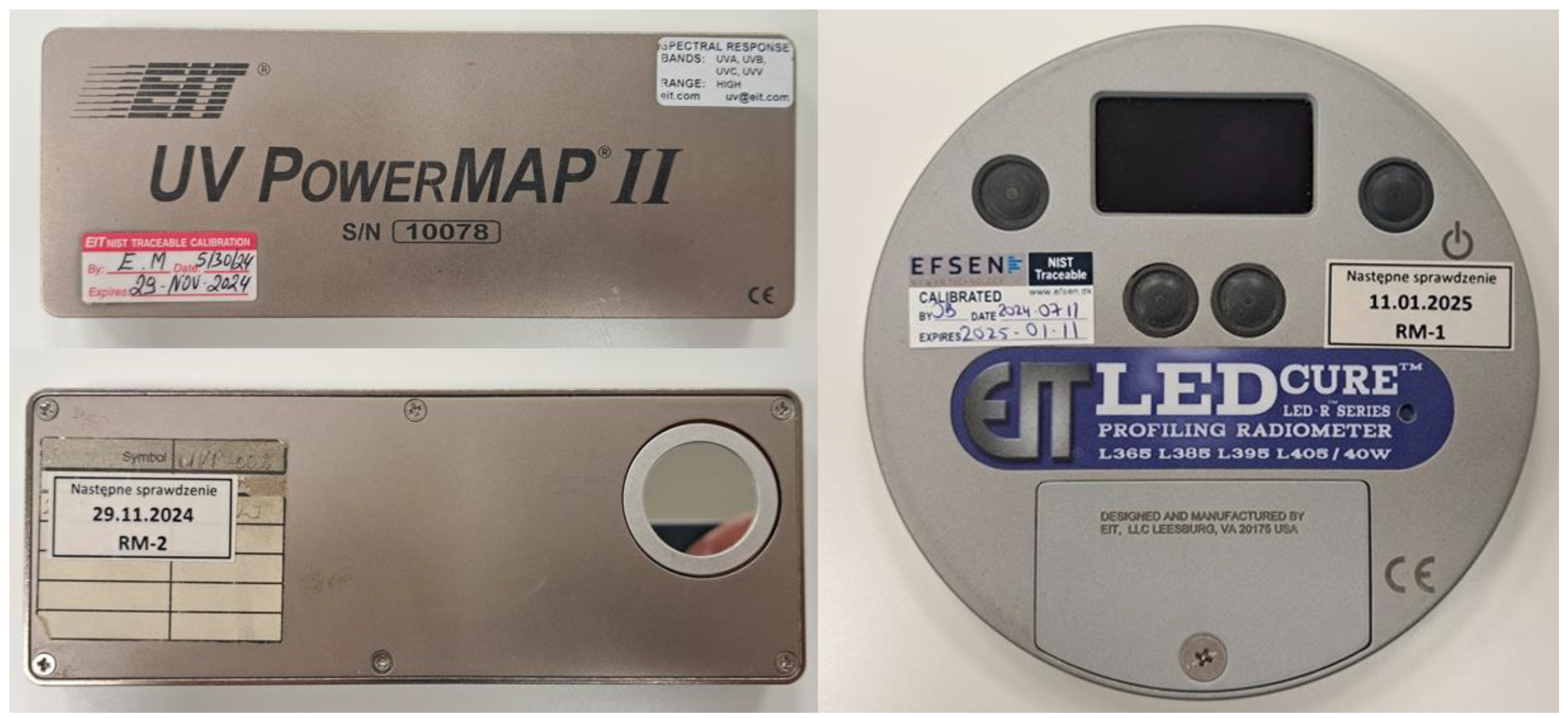
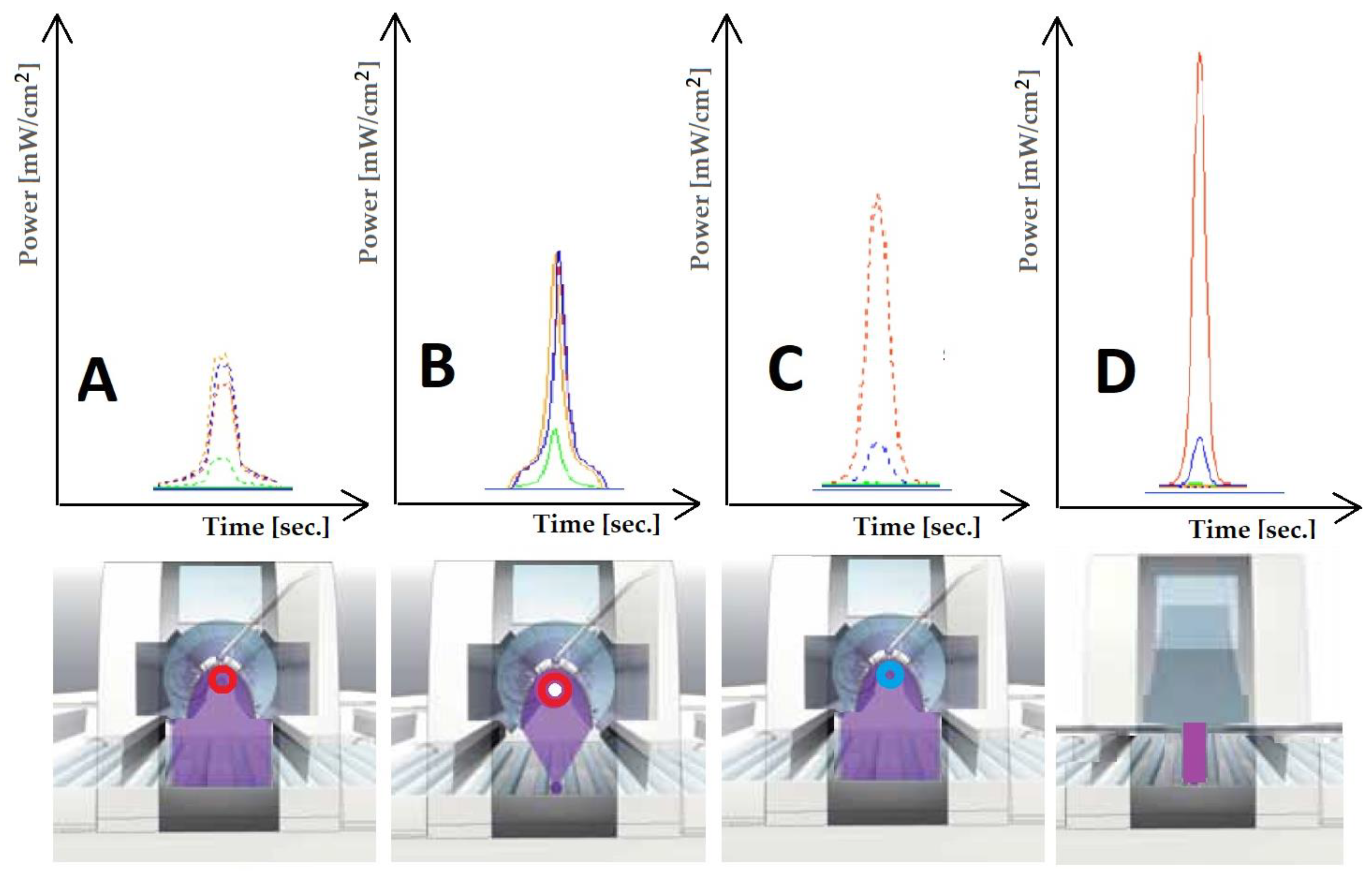
2.2.1. Measurements of Energy
2.2.2. Roughness
2.2.3. Contact Angle
2.2.4. Adhesion Strength of Coatings
2.2.5. Surface Topography
3. Results
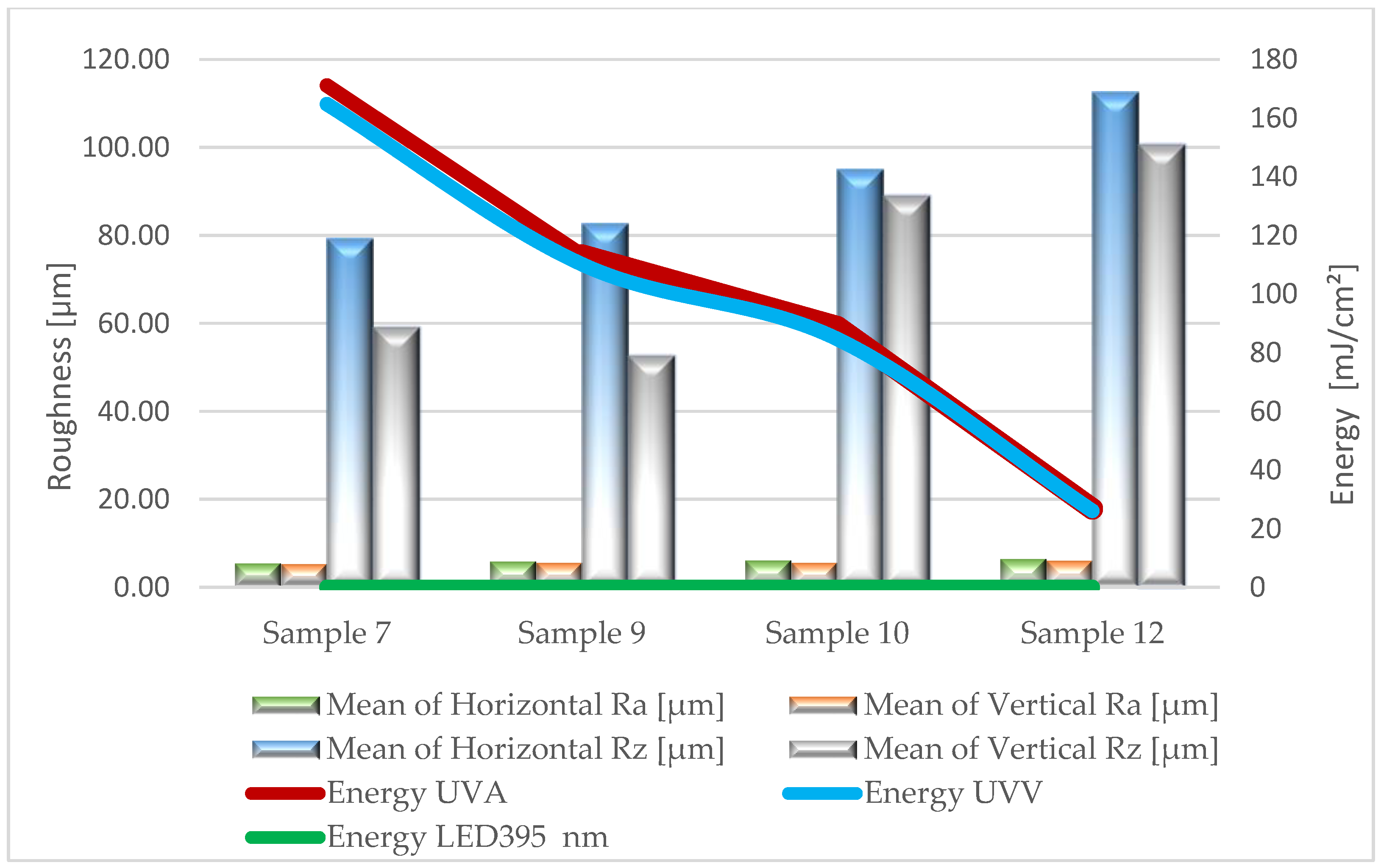
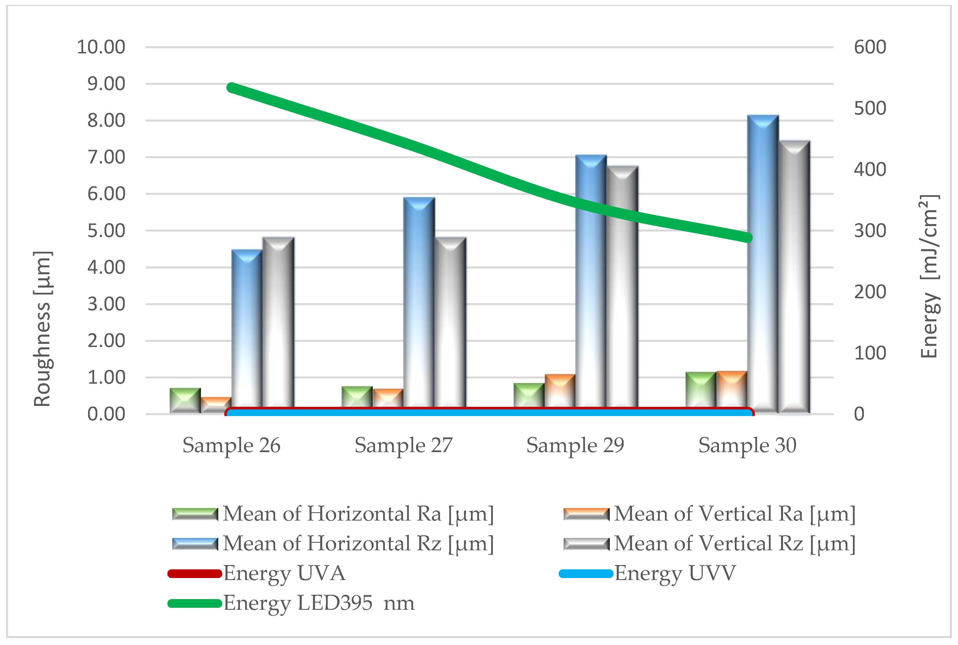
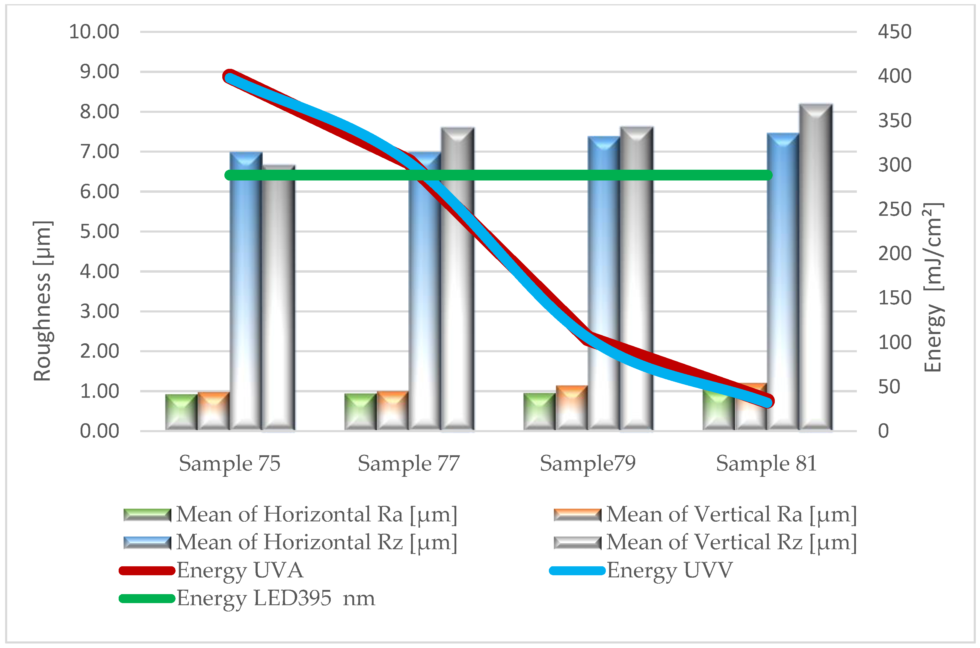
3.1. Roughness
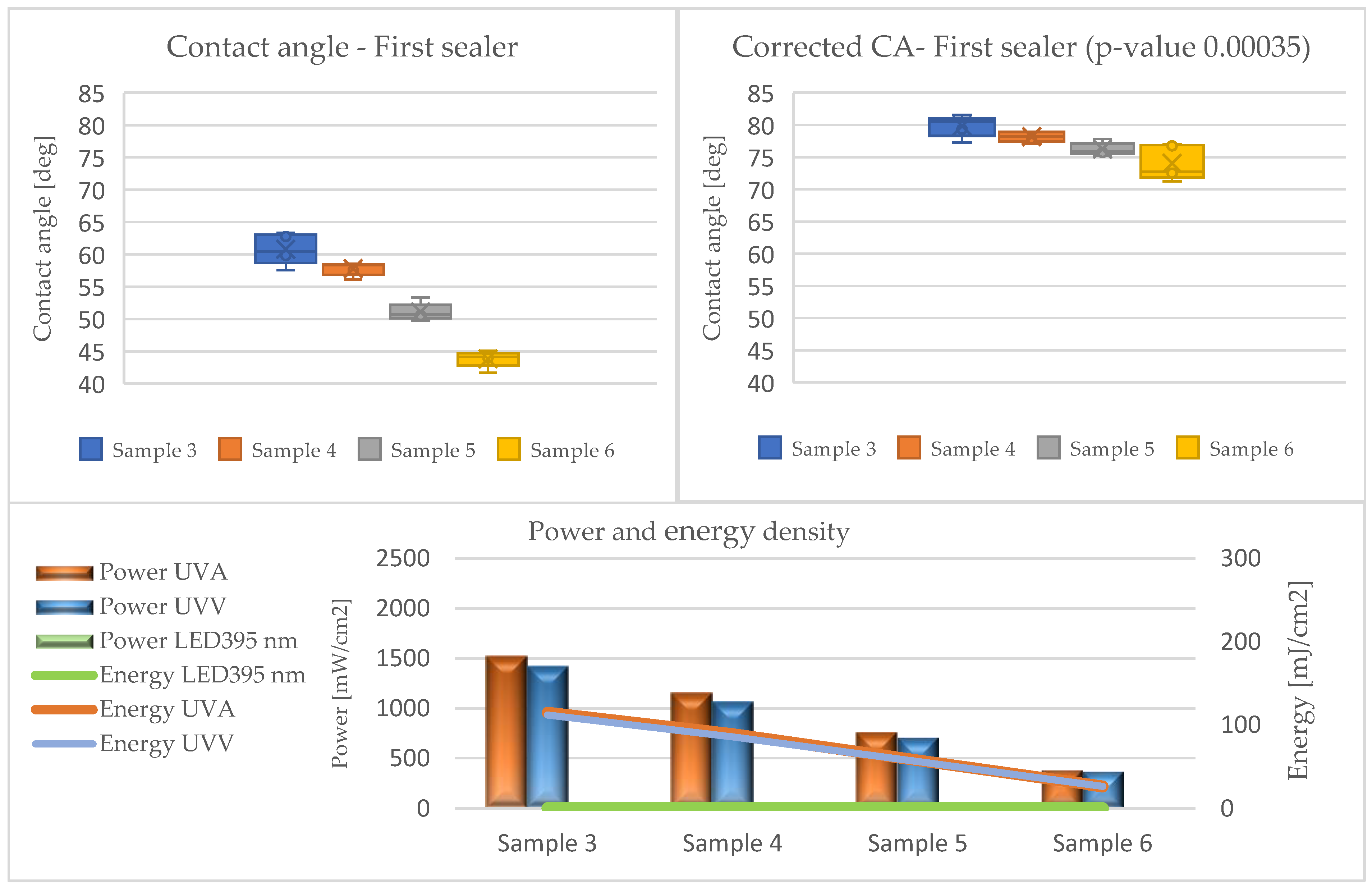
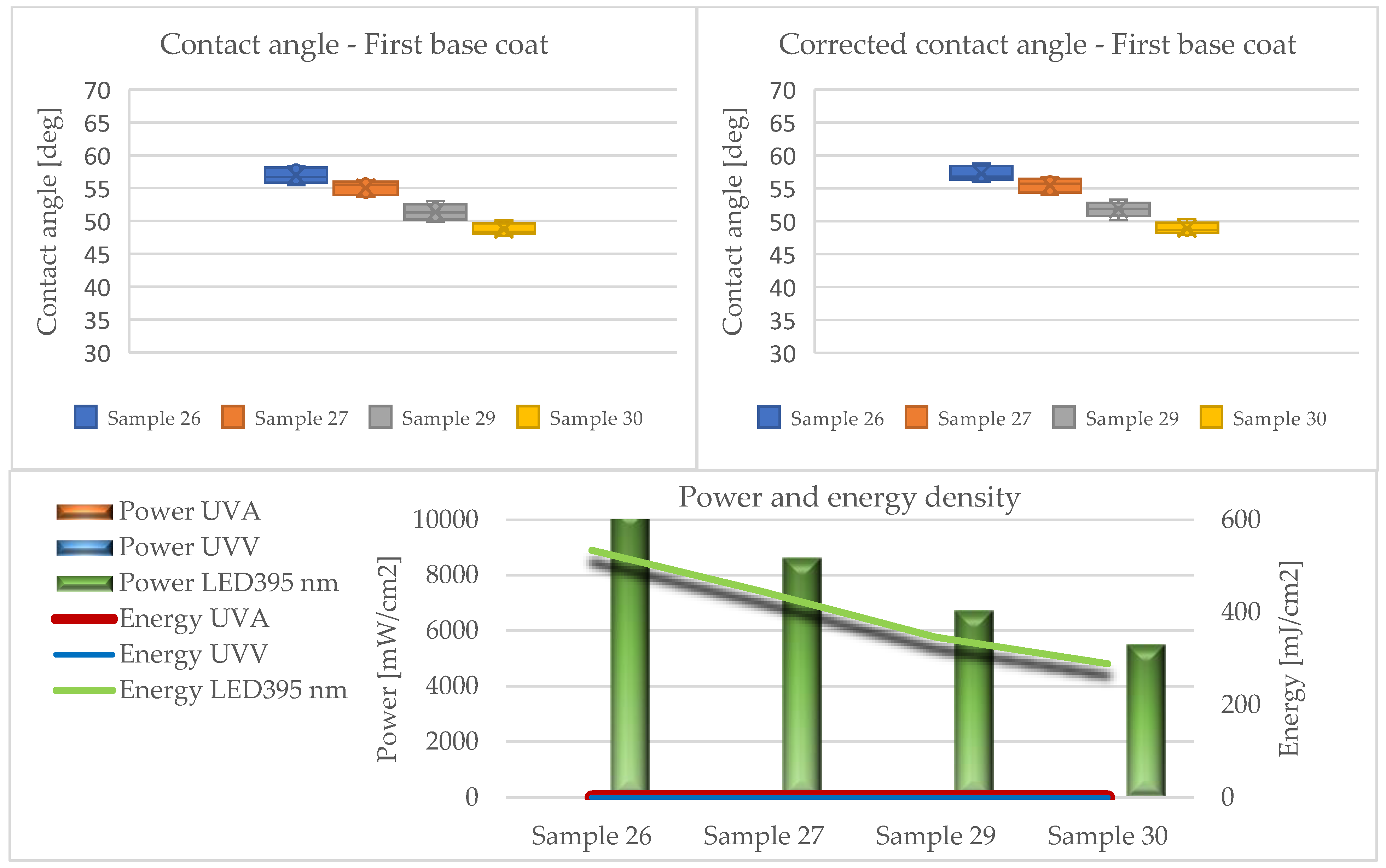
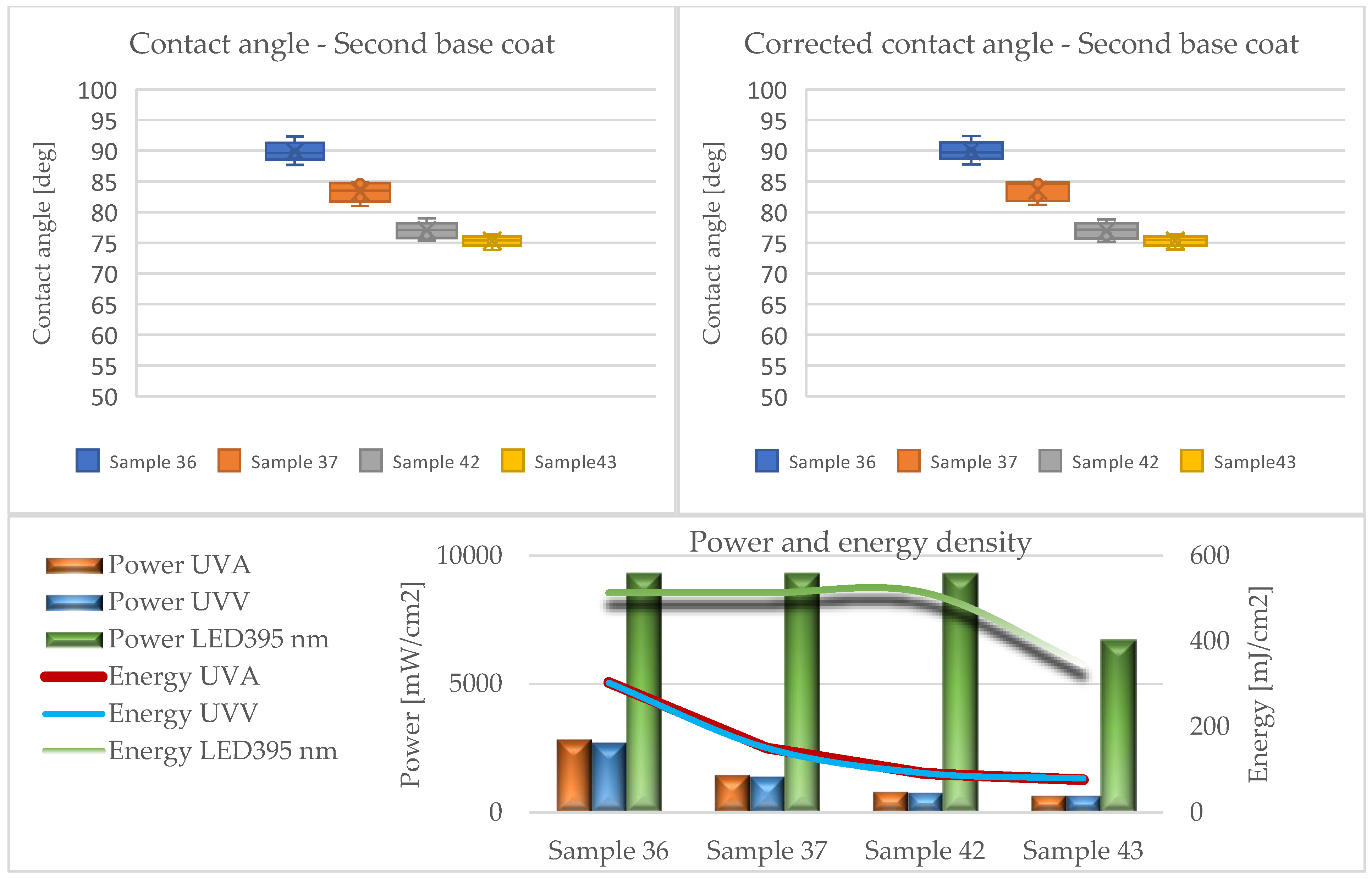
3.2. Contact Angle
3.3. Adhesion Strength
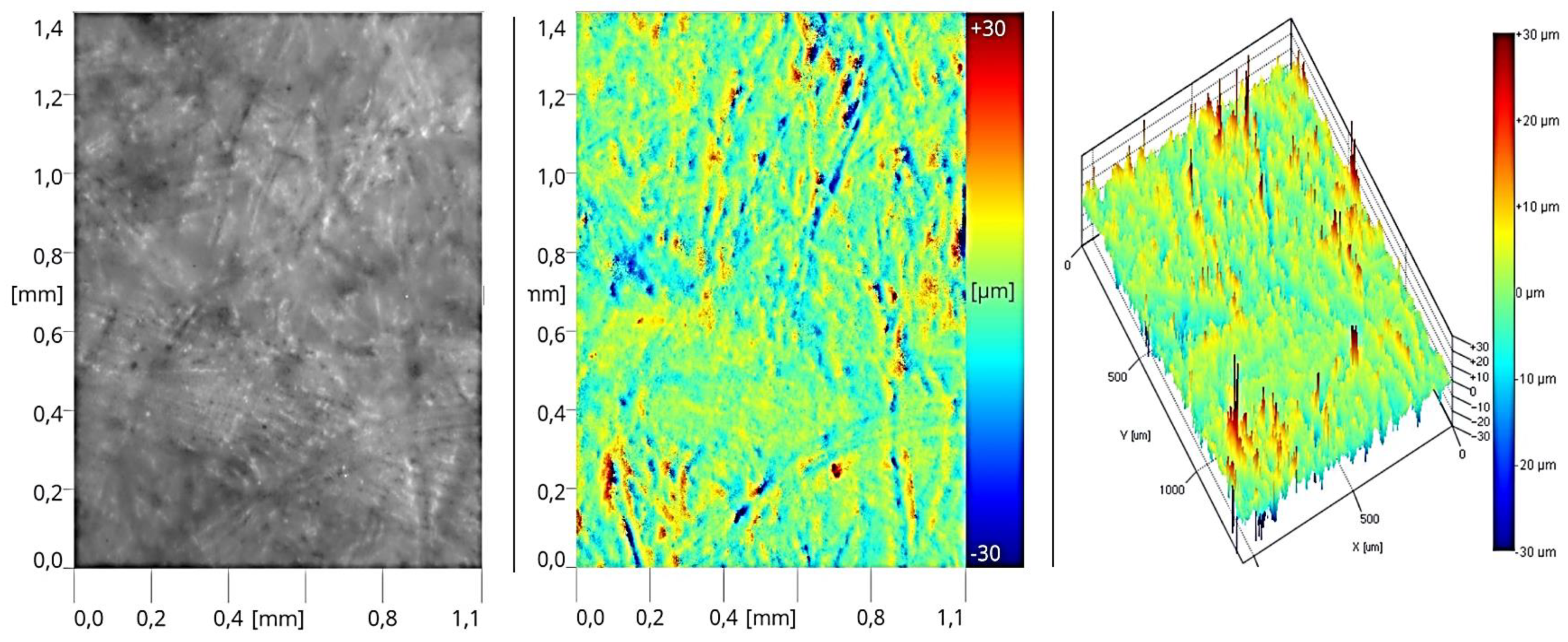
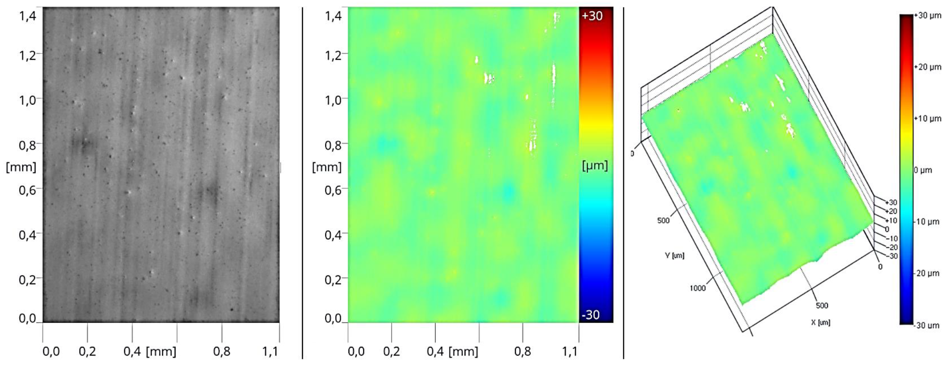
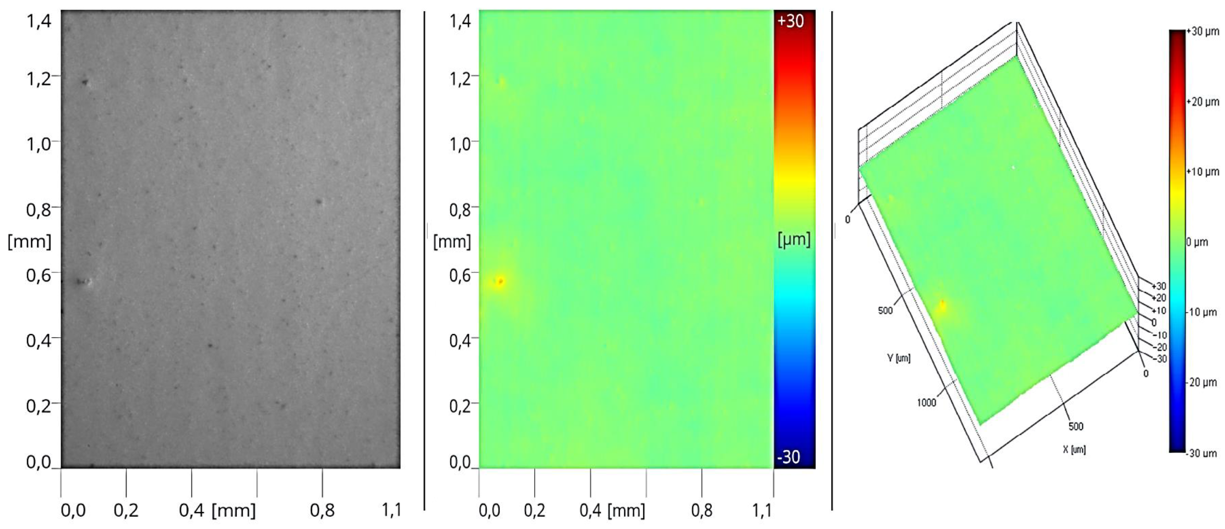
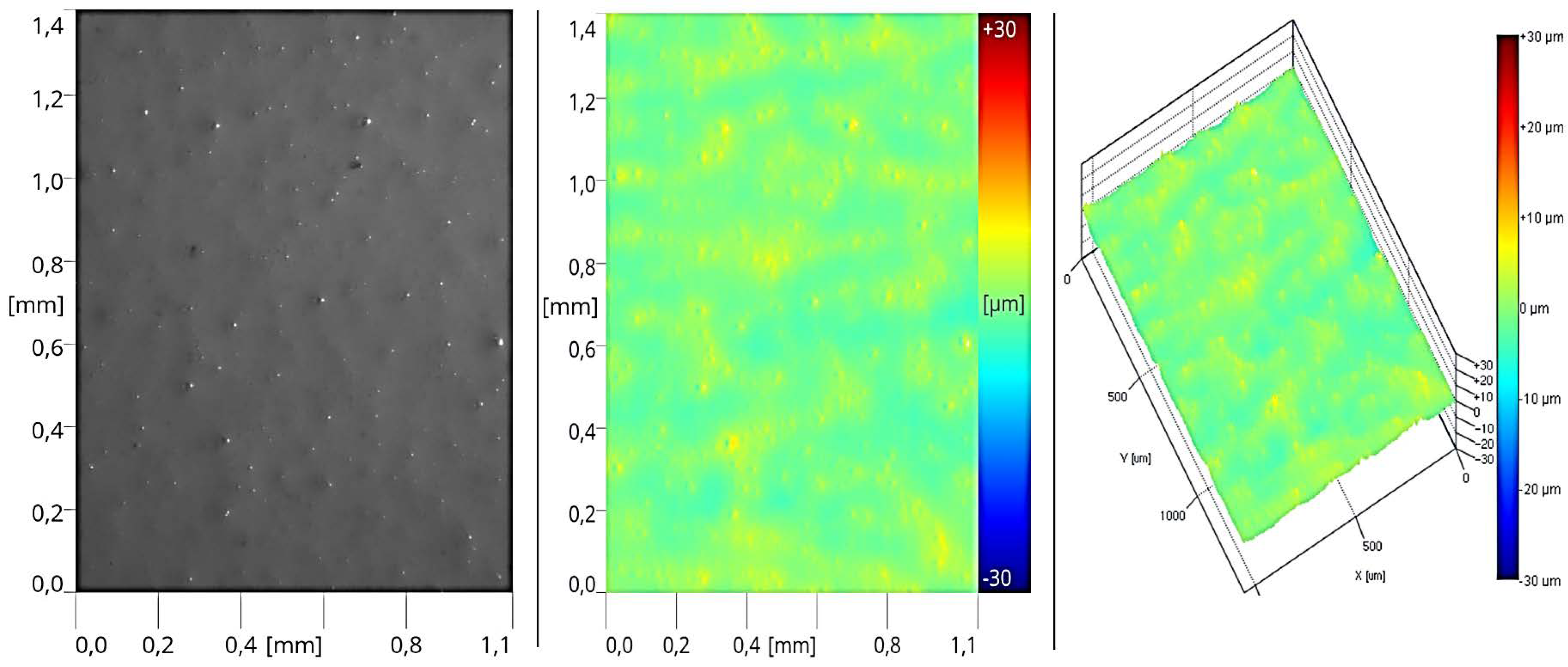
3.4. Estimation of Topography
3.5. Energy Consumption Analysis
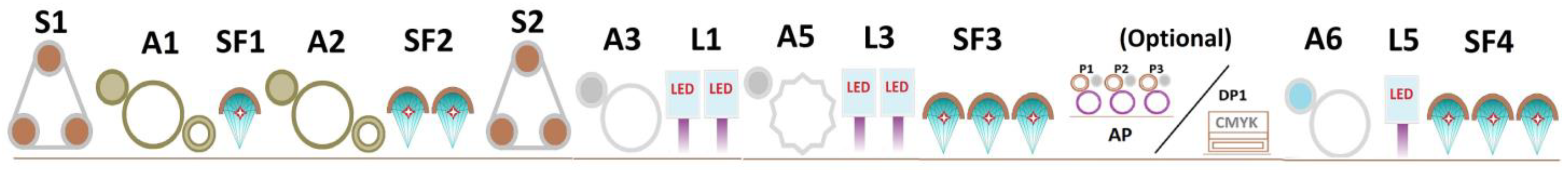
- Section 1: Curing of the surface after applying sealer layers (Stage I; Stage II);
- Section 2: Curing of the surface after applying the primer layer (Stage III; Stage IV);
- Section 3: Curing of the surface after applying the topcoat layer (Stage V).
4. Conclusions
- At all stages of the technological process, a decrease in the wetting angle was observed with a reduction in energy density. This effect was most noticeable in the initial stage, where the highest amounts of lacquer product were applied during the entire printing process and its preliminary pre-gelation.
- Significant differences between the angles (CA and CAc) were observed in the case of coatings formed from sealers (Stages I and II). The greatest discrepancies were noted with the lowest doses of UVA and UVV 26 mJ/cm2 for system no. 6, reaching up to 30 degrees. This confirms the need to consider the Wenzel correction factor when evaluating the wettability of HDF boards.
- As energy density decreases, the roughness of the coatings increases. The research did not reveal a clear trend in changes in the Ra and Rz parameter values depending on the measurement direction.
- Surface topography studies are useful for analyzing the finishing technology of HDF boards with UV coatings cured by Hg and LED lamps.
- The greatest energy savings, reaching up to 50%, were observed in Stages III and IV of the technological process, as a result of the application of UV LED emitters and modules focusing on electromagnetic radiation.
Author Contributions
Funding
Institutional Review Board Statement
Informed Consent Statement
Data Availability Statement
Acknowledgments
Conflicts of Interest
References
- Ozdemir, T.; Hiziroglu, S.; Kocapınar, M. Adhesion Strength of Cellulosic Varnish Coated Wood Species as Function of Their Surface Roughness. Adv. Mater. Sci. Eng. 2015, 6, 1–5. [Google Scholar] [CrossRef]
- Dilik, T.; Erdinler, E.; Hazir, E.; Koc, K.; Hiziroglu, S. Adhesion Strength of Wood Based Composites Coated with Cellulosic and Polyurethane Paints. Adv. Mater. Sci. Eng. 2015, 1, 1–5. [Google Scholar] [CrossRef]
- Pecina, H.; Paprzycki, O. Lack auf Holz; Vincentz Verlag: Hannover, Germany, 1995; Volume 1, p. 175. [Google Scholar]
- Proszyk, S. Technologia Tworzyw Drzewnych cz. 2. Wykończanie Powierzchni; WsiP: Warszawa, Poland, 1999; pp. 1–374. [Google Scholar]
- Van Iseghem, L.C. High-Quality Performance, UV-Curable Industrial Finishes for Wood. Radtech Rep. 2014, 2, 46–56. [Google Scholar]
- Dai, J.; Ma, S.; Wu, Y.; Liu, X. High bio-based content waterborne UV-curable coatings with excellent adhesion and flexibility. Prog. Org. Coat. 2015, 87, 197–203. [Google Scholar] [CrossRef]
- Zhao, Z.; Niu, Y.; Chen, F. Development and finishing technology of waterborne UV lacquer-coated wooden flooring. BioResources 2021, 16, 1101–1114. [Google Scholar] [CrossRef]
- Miklečić, J.; Jirous-Rajkovic, V. New Materials in Wood Finishing. In Wood is Good—New Materials, Quality and Design; ResearchGate: Zagreb, Croatia, 2009. [Google Scholar]
- Orwat, K.; Bernard, P.; Wróblewski, S.; Mendez, J.D. Traditional vs. UV-Cured coatings–an inquiry-based experiment for introducing green chemistry. Maced. J. Chem. Chem. Eng. 2018, 37, 215–224. [Google Scholar] [CrossRef]
- Proszyk, S. Postęp w dziedzinie wyrobów lakierowych i technologii ich stosowania w drzewnictwie. In Studia i szkice na Jubileusz Profesora Ryszarda Babickiego; Wyd. ITD: Poznań, Poland, 2007; pp. 115–123. [Google Scholar]
- Hwang, H.D.; Moon, J.I.; Choi, J.H.; Kim, H.J.; Kim, S.D.; Park, J.C. Effect of water drying conditions on the surface property and morphology of waterborne UV-curable coatings for engineered flooring. J. Ind. Eng. Chem. 2009, 15, 381–387. [Google Scholar] [CrossRef]
- Patil, D.M.; Phalak, G.A.; Mhaske, S.T. Design and synthesis of bio-based UV curable PU acrylate resin from itaconic acid for coating applications. Des. Monomers Polym. 2016, 20, 269–282. [Google Scholar] [CrossRef]
- Ulker, O.C.; Ulker, O.; Hiziroglu, S. Volatile Organic Compounds (VOCs) Emitted from Coated Furniture Units. Coatings 2021, 11, 806. [Google Scholar] [CrossRef]
- Kranig, W. Radiation Curing in Coatings. Chimia 1993, 47, 383–386. [Google Scholar] [CrossRef]
- Mashouf, G.; Ebrahimi, M.; Bastani, S. UV curable urethane acrylate coatings formulation: Experimental design approach. Pigment. Resin Technol. 2014, 43, 61–68. [Google Scholar] [CrossRef]
- Nkeuwa, W.N.; Riedl, B.; Landry, V. Wood surfaces protected with transparent multilayer UV-cured coatings reinforced with nanosilica and nanoclay. Part I: Morphological study and effect of relative humidity on adhesion strength. J. Coat. Technol. Res. 2014, 11, 283–301. [Google Scholar] [CrossRef]
- Guo, X.; Li, R.; Teng, Y.; Cao, P.; Wang, X.A.; Ji, F. Effects of surface treatment on the properties of UV coating. Wood Res. 2015, 60, 629–638. [Google Scholar]
- Palija, T.; Jaić, M.; Džinčić, I.; Šućur, A.; Dobić, J. Variability of dry film thickness of a coating applied by roller coater on wood in a real industrial process. Drewno 2018, 61, 153–164. [Google Scholar] [CrossRef]
- Yan, X.; Qian, X.; Lu, R.; Miyakoshi, T. Synergistic Effect of Addition of Fillers on Properties of Interior Waterborne UV-Curing Wood Coatings. Coatings 2018, 8, 9. [Google Scholar] [CrossRef]
- Angelsky, D. Influences of some factors upon the accelerated curing of pigmented polyurethane gloss top-coat by UV irra-diation. In Proceedings of the 9th Hardwood Conference, Sopron, Hungary, 21–22 October 2020; pp. 7–12. [Google Scholar]
- Ibrahim, M.S.; Heba, A.M.; Moustafa, M.E.; Talaat, Y.M.; Ashraf, A. A Comparative Study of Ultraviolet and Electron Beam Irradiation on Acrylate Coatings. Egypt. J. Chem. 2020, 63, 1931–1940. [Google Scholar] [CrossRef]
- Salca, E.A.; Krystofiak, T.; Lis, B.; Mazela, B.; Proszyk, S. Some coating properties of black alder wood as function of varnish type and applications method. BioResources 2016, 11, 7580–7594. [Google Scholar] [CrossRef]
- Çavuş, V. Weathering performance of mulberry wood with UV varnish applied and its mechanical properties. BioResources 2021, 16, 6791–6798. [Google Scholar] [CrossRef]
- Al-Mahdi, H.O. Study of UV Curing in the Wood Industry; Department of Wood, Paper and Coating Technology, School of Industrial Technology University Science Malaysia: Pulau Pinang, Malaysia, 1999; pp. 145–152. Available online: https://inis.iaea.org/collection/NCLCollectionStore/_Public/31/016/31016316.pdf (accessed on 10 July 2024).
- Arceneaux, J.A. Field Applied UV Curable Floor Coatings. Available online: https://www.google.com/url?sa=t&source=web&rct=j&opi=89978449&url=https://www.radtech.org/proceedings/2010/papers/1467.pdf&ved=2ahUKEwjJhde5w8qHAxVaGBAIHeEvL7cQFnoECBYQAQ&usg=AOvVaw1D3GDmtBIotUb-3sulqa4Q (accessed on 10 July 2024).
- Lis, B.; Proszyk, S.; Krystofiak, T. Low energy consuming of hardening of lacquer coatings by means of UV–LED radiators. Inthercathedra 2009, 25, 75–79. [Google Scholar]
- Borysiuk, P.; Derda, M.; Auriga, R.; Boruszewski, P.; Monder, S. Comparison of Selected Properties of Varnish Coatings Curing with the Use of UV and UV-LED Approach. Ann. WULS SGGW For. Wood Technol. 2015, 92, 49–54. [Google Scholar]
- Landry, V.; Blanchet, P.; Boivin, G.; Bouffard, J.-F.; Vlad, M. UV-LED Curing Efficiency of Wood Coatings. Coatings 2015, 5, 1019–1033. [Google Scholar] [CrossRef]
- Pawlak, D.; Boruszewski, P. Digital printing in wood industry. Ann. WULS For. Wood Technol. 2020, 109, 109–115. [Google Scholar] [CrossRef]
- Pugliese, D.; Malucelli, G. UV-LED Curable Acrylic Films Containing Phosphate Glass Powder: Effect of the Filler Loading on the Thermal, Optical, Mechanical and Flame Retardant Properties. Polymers 2022, 14, 1899. [Google Scholar] [CrossRef] [PubMed]
- Wang, X.; Feng, Y.; Zhang, L. Fast-cured UV-LED polymer materials filled with high mineral contents as wear-resistant, antibacterial coatings. Chem. Eng. J. 2020, 382, 122927. [Google Scholar] [CrossRef]
- Patil, R.S.; Thomas, J.; Patil, M.; John, J. To Shed Light on the UV Curable Coating Technology: Current State of the Art and Perspectives. J. Compos. Sci. 2023, 7, 513. [Google Scholar] [CrossRef]
- Stowe, R.W. Practical aspects of irradiance and energy in UV curing. In Proceedings of the RADTECH ASIA ’99. Radiation Curing: The Technology for the Next Millenium, Kuala Lumpur, Malaysia, 24–26 August 1999; p. 552, Malaysian Institute for Nuclear Technology Research, MINT. Available online: https://inis.iaea.org/search/search.aspx?orig_q=RN:31016357 (accessed on 5 July 2024).
- Anonymous. NewV® UV curing inks and varnishes for offset printing. In Technical Information; Hubergroup: Rolling Meadows IL, USA, 2017. [Google Scholar]
- Kiyoi, E. The State of UV-LED Curing. Radtech Rep. 2013, 2, 32–36. [Google Scholar]
- Anonymous. Utwardzanie UV LED: Zrównoważony rozwój i większe zyski. Świat Druku 2023, 5, 1. [Google Scholar]
- Tokarczyk, M.; Lis, B.; Krystofiak, T. Interlayer Adhesion of Coating System in Analogue and Digital Printing Technologies Formed on Lightweight Honeycomb Furniture Panels. Coatings 2024, 14, 1124. [Google Scholar] [CrossRef]
- Tokarczyk, M. Method for Manufacturing a Cellular Plate and a Cellular Plate Manufactured by this. Method. Patent PL234055B1, 5 June 2017. [Google Scholar]
- Tokarczyk, M.; Behrendt, A. Sposób Wytwarzania Ultralekkiej Płyty Komórkowej na Blokach i Ultralekka Płyta Komórkowa na. Blokach. Patent P.443573, 6 May 2016. [Google Scholar]
- Anonymous. Attension Theta Topography Evaluate the Influence of Roughness to Wettability. Available online: https://cdn2.hubspot.net/hubfs/516902/Pdf/Attension/Brochures/attension-theta-topography-module.pdf (accessed on 10 July 2024).
- Anonymous. Theta Flex User Manual—OneAttension Original Instructions; Biolin Scientific Oy: Espoo, Finland, 2019; p. 74. [Google Scholar]
- PN-EN ISO 4624:2016-5; Farby i Lakiery—Próba Odrywania do Oceny Przyczepności. Polish Committee for Standardization: Warsaw, Poland, 2016.
- Jaczewski, M. Chropowatość powierzchni. Lakiernictwo Przemysłowe 2016, 5, 1–4. [Google Scholar]
- Tokarczyk, M.; Lis, B.; Salca, E.A.; Krystofiak, T. Adhesion of Varnish Coatings as a Background for Analogue and Digital Printing Technologies. Appl. Sci. 2024, 14, 304. [Google Scholar] [CrossRef]
- Hazir, E.; Koc, K.H. A modeling study to evaluate the quality of wood Surface. Maderas Cienc. Tecnol. 2018, 20, 691–702. [Google Scholar] [CrossRef]
- Henke, M.; Lis, B.; Krystofiak, T. Evaluation of Surface Roughness Parameters of HDF for Finishing under Industrial Conditions. Materials 2022, 15, 6359. [Google Scholar] [CrossRef] [PubMed]
- Nakae, H.; Inui, R.; Hirata, Y.; Saito, H. Effects of surface roughness on wettability. Acta Materialia 1998, 46, 2313–2318. [Google Scholar] [CrossRef]
- Żenkiewicz, M. Adhezja i Modyfikowanie Warstwy Wierzchniej Tworzyw Wielkocząsteczkowych; Wydawnictwo Naukowo-Techniczne: Warszawa, Polska, 2000; pp. 81–83. [Google Scholar]


| Name of UV Varnish Products | |||||
|---|---|---|---|---|---|
| Properties | IQ-UV 03040 Sealer | IQ-UVC03284 Basecoat | IQ-UVC03285 Basecoat | IQ-HYC02486 Ink | IQ-HYC02806 Topcoat |
| Polymer base | acrylic | acrylic | acrylic | waterborne | acrylic |
| Color | colorless | white | white | black | white |
| Solid content [%] | 95.3 ± 3 | 97.6 ± 3 | 97.5 ± 3 | 20 ± 3 | 97.5 ± 3 |
| Viscosity of delivery | 65–85 | 90–140 | 35–50 | 20–35 | 30–40 |
| (flow cup 8 mm) | (flow cup 6 mm) | (flow cup 8 mm) | (flow cup 4 mm) | (flow cup 6 mm) | |
| Processing temperature [°C] | Between 20–50 | ||||
| Samples | Speed [m/min] | Amount for Layer [g/m2] | Type | Power UVA [mW/cm2] | Power UVV [mW/cm2] | Energy UVA [mJ/cm2] | Energy UVV [mJ/cm2] | Power LED395 [mW/cm2] | Energy LED395 [mJ/cm2] |
|---|---|---|---|---|---|---|---|---|---|
| Process sheme (Stage I) |  | ||||||||
| 3 | 40 | 50 | sealer | 1523 | 1421 | 115 | 112 | - | - |
| 4 | 40 | 50 | sealer | 1155 | 1066 | 89 | 86 | - | - |
| 5 | 40 | 50 | sealer | 761 | 711 | 57 | 56 | - | |
| 6 | 40 | 50 | sealer | 385 | 369 | 26 | 26 | - | - |
| Process sheme (Stage II) |  | ||||||||
| 7 | 40 | 25 | sealer | 2385 | 2211 | 171 | 165 | - | - |
| 9 | 40 | 25 | sealer | 1640 | 1538 | 113 | 110 | - | - |
| 10 | 40 | 25 | sealer | 1238 | 1136 | 89 | 85 | - | - |
| 12 | 40 | 25 | sealer | 363 | 346 | 27 | 26 | - | - |
| Process sheme (Stage III) |  | ||||||||
| 26 | 40 | 12 | basecoat 1 | - | - | - | - | 10,420 | 534 |
| 27 | 40 | 12 | basecoat 1 | - | - | - | - | 8617 | 444 |
| 29 | 40 | 12 | basecoat 1 | - | - | - | - | 6721 | 346 |
| 30 | 40 | 12 | basecoat 1 | - | - | - | - | 5501 | 289 |
| Process sheme (Stage IV) | 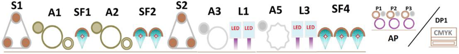 | ||||||||
| 36 | 40 | 30 | basecoat 2 | 2865 | 2742 | 304 | 303 | 9327 | 513 |
| 37 | 40 | 30 | basecoat 2 | 1487 | 1428 | 150 | 150 | 9327 | 513 |
| 42 | 40 | 30 | basecoat 2 | 827 | 797 | 91 | 92 | 9327 | 513 |
| 43 | 40 | 30 | basecoat 2 | 677 | 676 | 77 | 80 | 6721 | 346 |
| Process sheme (Stage V) | 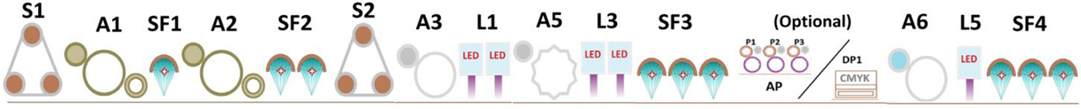 | ||||||||
| 75 | 40 | 5 | topcoat | 3560 | 3397 | 400 | 398 | 5501 | 289 |
| 77 | 40 | 5 | topcoat | 2865 | 2742 | 304 | 303 | 5501 | 289 |
| 79 | 40 | 5 | topcoat | 960 | 931 | 104 | 105 | 5501 | 289 |
| 81 | 40 | 5 | topcoat | 364 | 361 | 34 | 32 | 5501 | 289 |
| Method | Fringe Projection Phase Shifting |
|---|---|
| XY pixel size: | 1.1 μm × 1.1 μm |
| Measured range in Z direction | 1 μm–60 μm |
| Lateral sampling (XY): | 1.41 mm × 1.06 mm |
| Measurement speed | 5–30 s (1280 × 960 measurement points) |
| Imaging options | Optical image, 2D and 3D roughness graphs |
| Method: | Fringe projection phase shifting |
| XY pixel size: | 1.1 μm × 1.1 μm |
| Measured range in Z direction | 1 μm–60 μm |
| Lateral sampling (XY): | 1.41 mm × 1.06 mm |
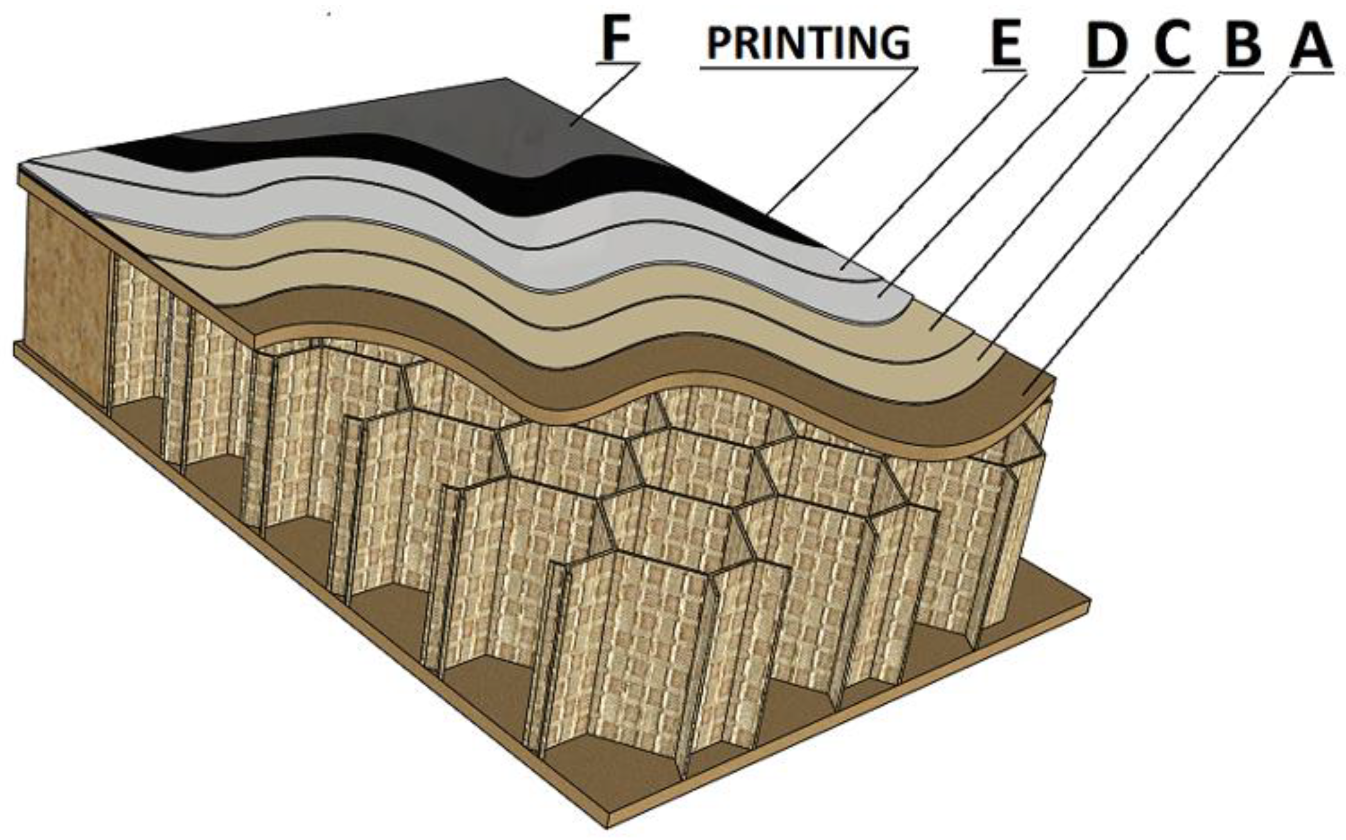
| Detachment Type | Detachment Occurring in a Given System |
|---|---|
| A | Cohesive in a substrate |
| A/B | Adhesive between a substrate and the first sealer |
| B | Cohesive in the first sealer |
| B/C | Adhesive between the first sealer and second sealer |
| C | Cohesive in the second sealer |
| C/D | Adhesive between the second sealer and first basecoat |
| D | Cohesive in the first basecoat |
| D/E | Adhesive between the first basecoat and second basecoat |
| E | Cohesive in the second basecoat |
| E/PRINTING | Adhesive between the second basecoat and printing |
| PRINTING | Cohesive in the printing |
| PRINTING/F | Adhesive between the printing and topcoat |
| F | Cohesive in the topcoat |
| Samples | Speed [m/min] | Amount for Last Layer [g/m2] | Type | Evaluation of Adhesion [%] | ||||
|---|---|---|---|---|---|---|---|---|
| 3 | 40 | 50 | sealer | 80A, 20A/B | 100A | 100A | 100A | 100A |
| 4 | 40 | 50 | sealer | 90A, 10A/B | 100A | 100A | 100A | 80A, 20A/B |
| 5 | 40 | 50 | sealer | 60A, 40A/B | 25A, 75A/B | 40A, 60A/B | 60A, 40A/B | 40A, 60A/B |
| 6 | 40 | 50 | sealer | 80A, 20A/B | 70A, 30A/B | 30A, 70A/B | 40A, 60A/B | 20A, 80A/B |
| 7 | 40 | 25 | sealer | 100A | 100A | 95A, 5A/B | 100A | 100A |
| 9 | 40 | 25 | sealer | 100A | 100A | 100A | 95A, 5A/B | 90A, 5B, 5A/B |
| 10 | 40 | 25 | sealer | 80A, 20C | 85A, 15C | 90A, 10C | 85A, 15C | 85A, 15C |
| 12 | 40 | 25 | sealer | 70A, 30C | 85A, 5C, 10B/C | 85A, 10C, 5B/C | 70A, 30C | 95A, 5B/C |
| 26 | 40 | 12 | basecoat 1 | 100A | 100A | 90A, 10A/B | 70A, 30A/B | 100A |
| 27 | 40 | 12 | basecoat 1 | 100A | 90A, 10A/B | 100A | 70A, 30A/B | 100A |
| 29 | 40 | 12 | basecoat 1 | 70A,30A/B | 50A, 50A/B | 100A | 90A, 10A/B | 100A |
| 30 | 40 | 12 | basecoat 1 | 20A, 80C/D | 100C/D | 15A, 85C/D | 15A, 85C/D | 25A, 75C/D |
| 36 | 40 | 30 | basecoat 2 | 100E/Printing | 100E/Printing | 100E/Printing | 100E/Printing | 100E/Printing |
| 37 | 40 | 30 | basecoat 2 | 100E/Printing | 100A | 10A, 90E/Printing | 20A, 80E/Printing | 100A |
| 42 | 40 | 30 | basecoat 2 | 70A, 30E/AP | 100A | 90A, 10A/B | 100A | 100A |
| 43 | 40 | 30 | basecoat 2 | 70F, 20A, 10A/B | 70A, 30D/E | 100A | 100A | 5A, 95D/E |
| 75 | 40 | 5 | topcoat | 90A, 10A/B | 100A | 100A | 90A, 10A/B | 100A |
| 77 | 40 | 5 | topcoat | 100A | 100A | 80A, 20A/B | 100A | 80A, 20A/B |
| 79 | 40 | 5 | topcoat | 100A | 100A | 100A | 90A, 10A/B | 100A |
| 81 | 40 | 5 | topcoat | 100A | 80A, 20Print/F | 80A, 20Print/F | 100A | 100A |
| Measurement Section | Section 1 | Section 2 | Section 3 |
|---|---|---|---|
| Stage | Step I, Step II | Step III, Step IV | Step V |
| Process description | Curing of sealer layers | Curing of basecoat layers | Curing of topcoat layer |
| Average energy values standard line [Wh/m2] | 34.67 | 50.32 | 58.6 |
| Average energy values for research line [Wh/m2] | 23.44 | 25.46 | 43.8 |
| Energy Savings [%] | 32 | 50 | 25 |
Disclaimer/Publisher’s Note: The statements, opinions and data contained in all publications are solely those of the individual author(s) and contributor(s) and not of MDPI and/or the editor(s). MDPI and/or the editor(s) disclaim responsibility for any injury to people or property resulting from any ideas, methods, instructions or products referred to in the content. |
© 2024 by the authors. Licensee MDPI, Basel, Switzerland. This article is an open access article distributed under the terms and conditions of the Creative Commons Attribution (CC BY) license (https://creativecommons.org/licenses/by/4.0/).
Share and Cite
Tokarczyk, M.; Lis, B.; Krystofiak, T. Influence of Finishing Process Parameters of HDF Boards on Selected Properties of Coatings in Modern UV Lines and Their Relation to Energy Consumption. Materials 2024, 17, 5393. https://doi.org/10.3390/ma17225393
Tokarczyk M, Lis B, Krystofiak T. Influence of Finishing Process Parameters of HDF Boards on Selected Properties of Coatings in Modern UV Lines and Their Relation to Energy Consumption. Materials. 2024; 17(22):5393. https://doi.org/10.3390/ma17225393
Chicago/Turabian StyleTokarczyk, Maciej, Barbara Lis, and Tomasz Krystofiak. 2024. "Influence of Finishing Process Parameters of HDF Boards on Selected Properties of Coatings in Modern UV Lines and Their Relation to Energy Consumption" Materials 17, no. 22: 5393. https://doi.org/10.3390/ma17225393
APA StyleTokarczyk, M., Lis, B., & Krystofiak, T. (2024). Influence of Finishing Process Parameters of HDF Boards on Selected Properties of Coatings in Modern UV Lines and Their Relation to Energy Consumption. Materials, 17(22), 5393. https://doi.org/10.3390/ma17225393