
Fabrication, Processing, Properties, and Applications of Closed-Cell Aluminum Foams: A Review


Abstract
:1. Introduction
2. Fabrication
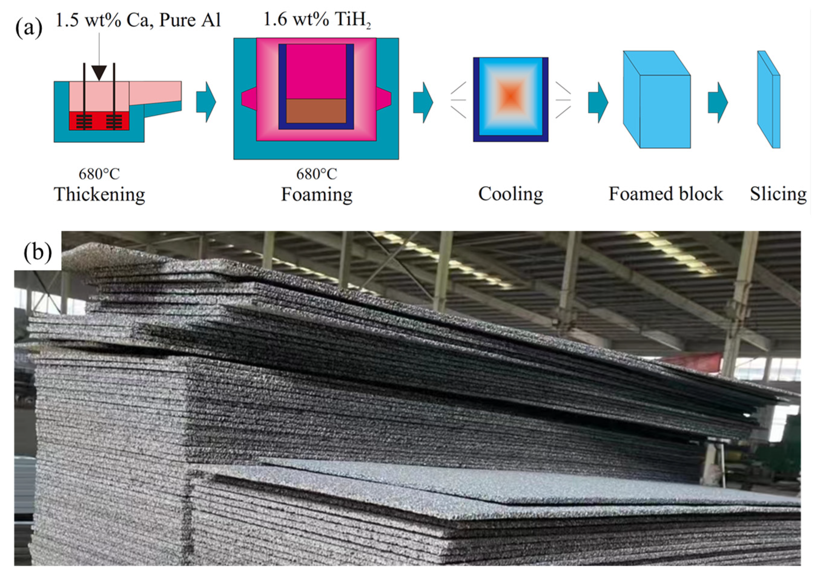
2.1. Melt Foaming Method
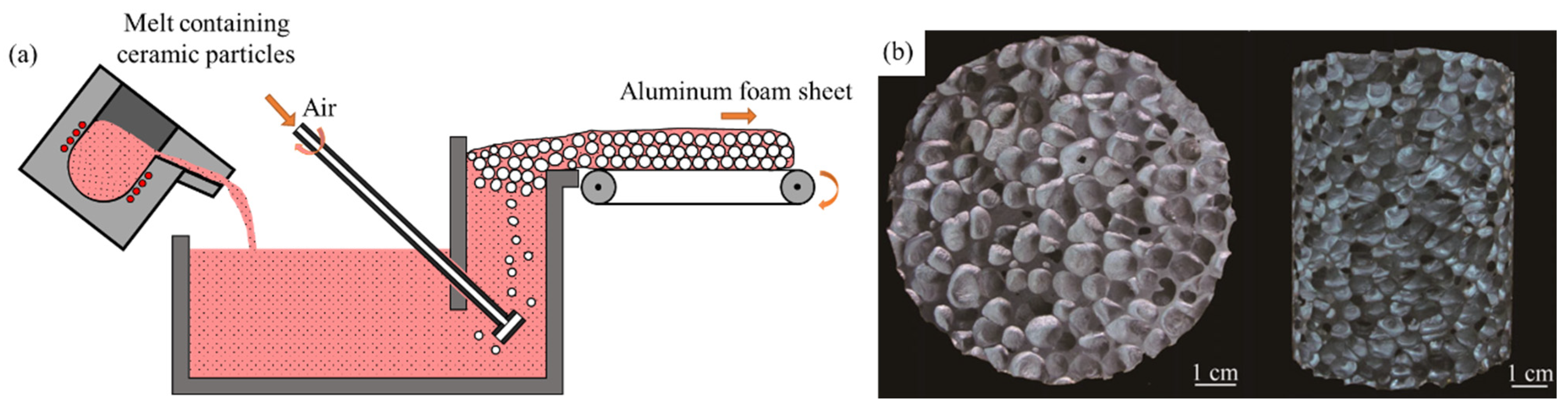
2.2. Gas Injection Foaming Method
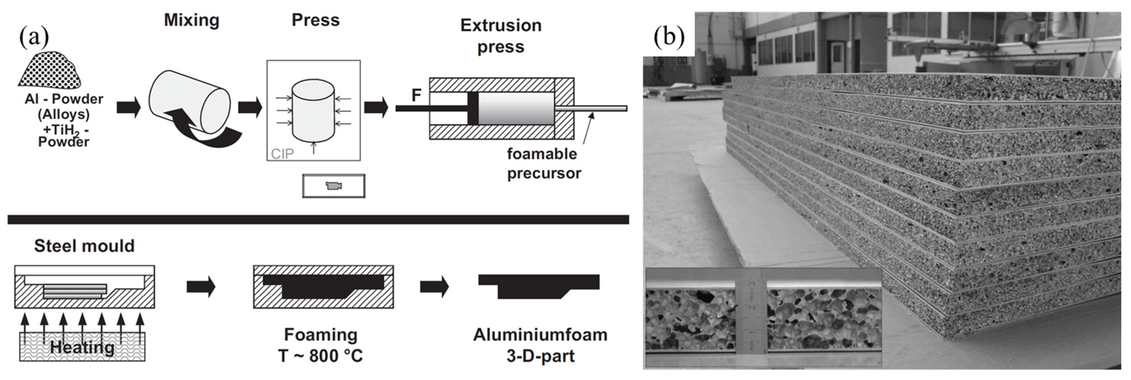
2.3. Powder Metallurgy Foaming Method
3. Processing
3.1. Powder Metallurgy Foaming Process
3.2. Two-Step Foaming Process
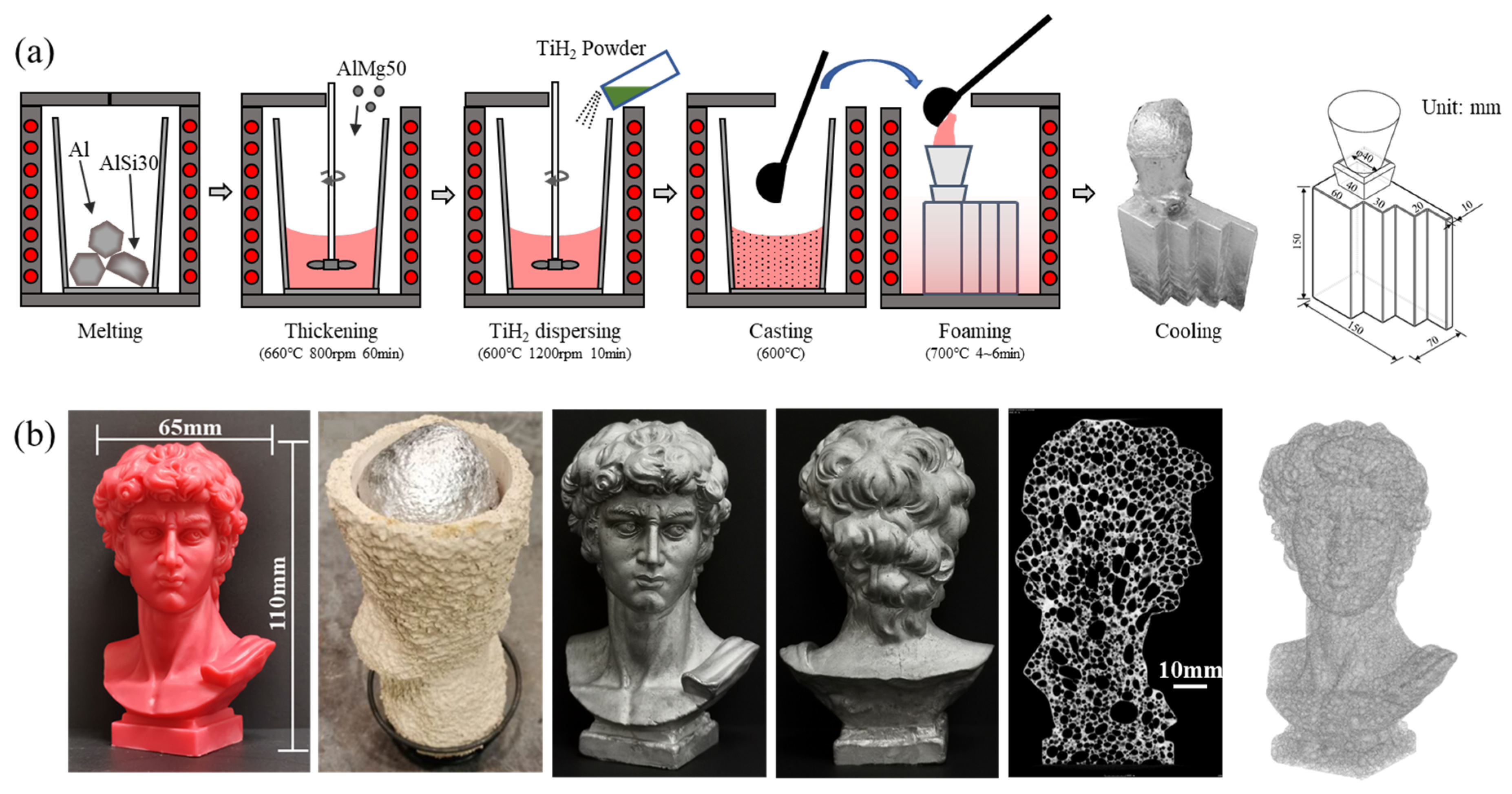
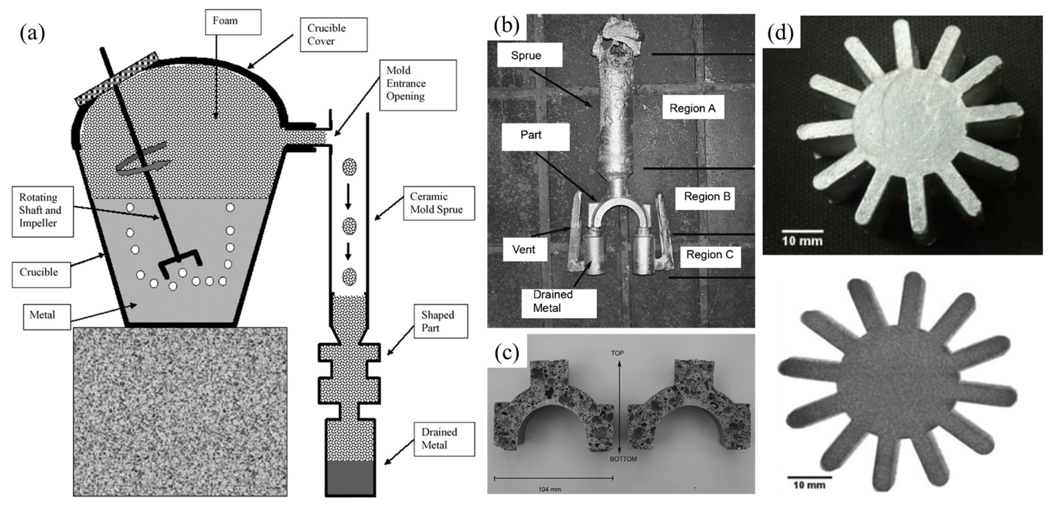
3.3. Cast Foaming Process
3.4. Gas Injection Foaming Process
3.5. Mold Pressing Process

3.6. Integral Foaming Process
3.7. Summary
4. Properties and Applications
4.1. Mechanical Properties
4.1.1. Basic Concepts
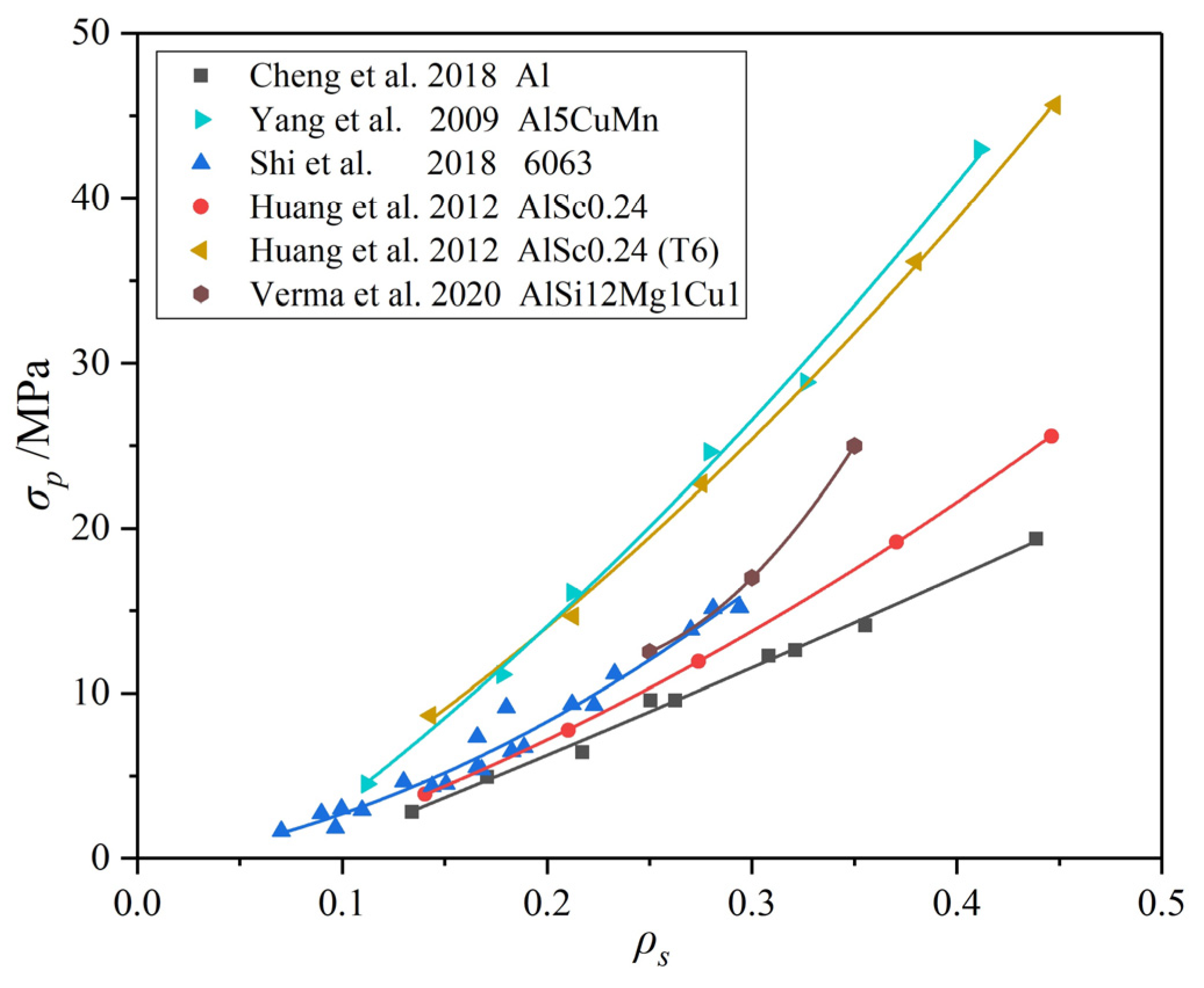
4.1.2. Influencing Factors
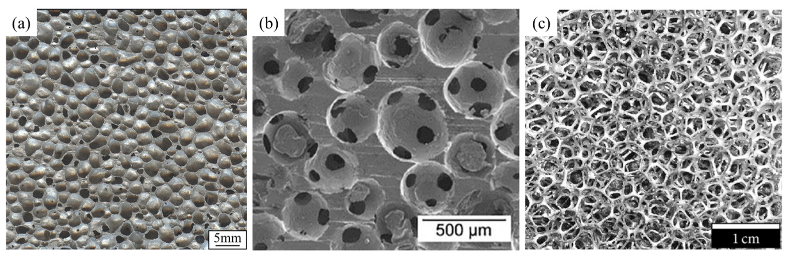
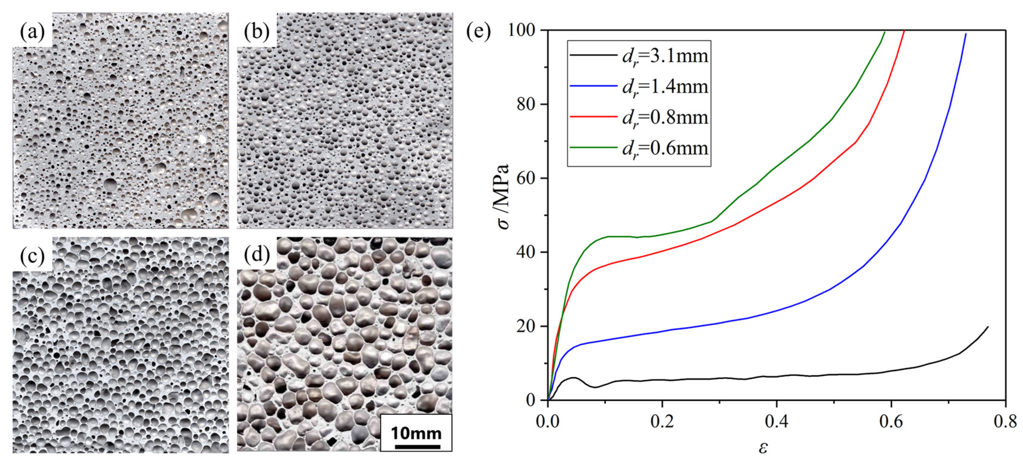
- Pore Structure
- Defects in the Cell Wall
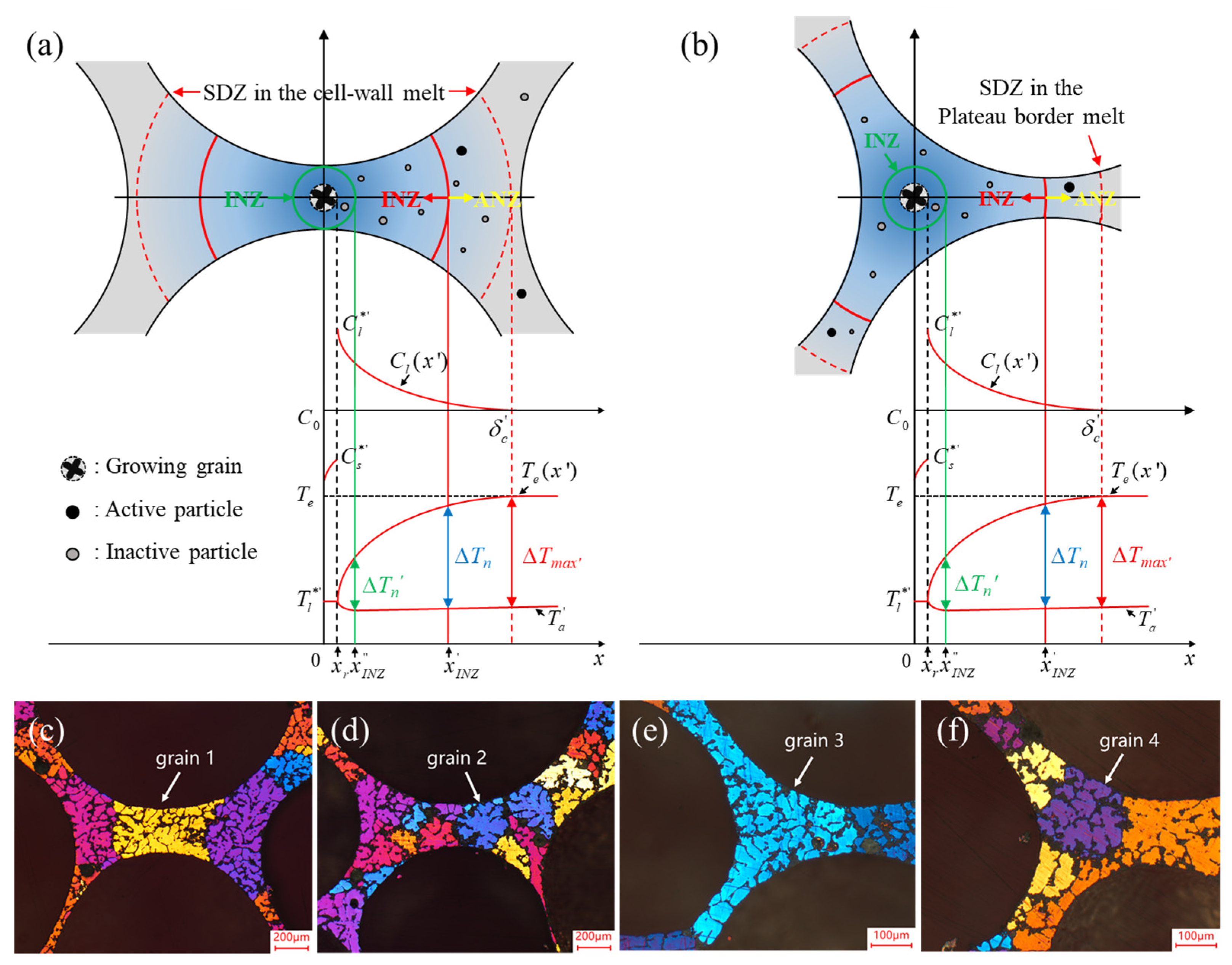
- Microstructure and Properties of the Cell Wall
4.1.3. Problems

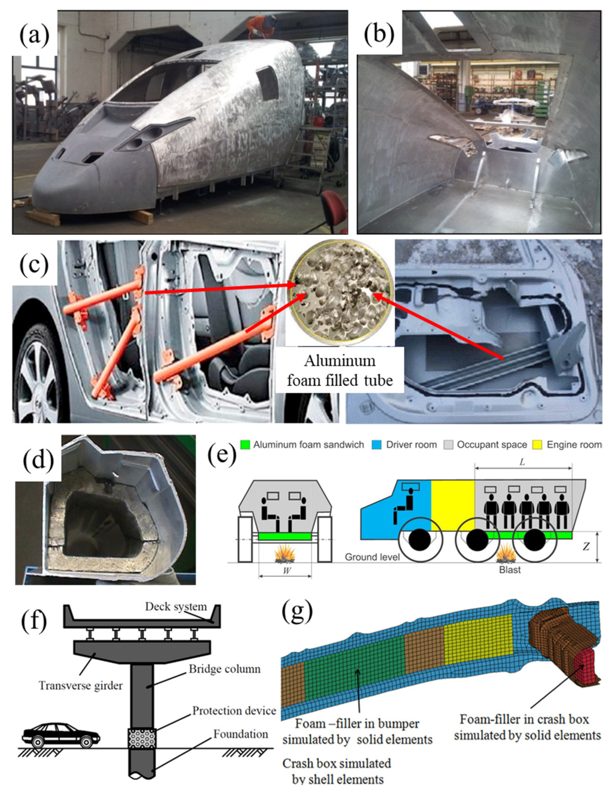
4.1.4. Applications
4.2. Physical Properties
4.2.1. Sound Absorption and Applications
4.2.2. Electromagnetic Shielding and Applications
4.2.3. Heat Insulation and Applications
5. Conclusions and Perspectives
- (1)
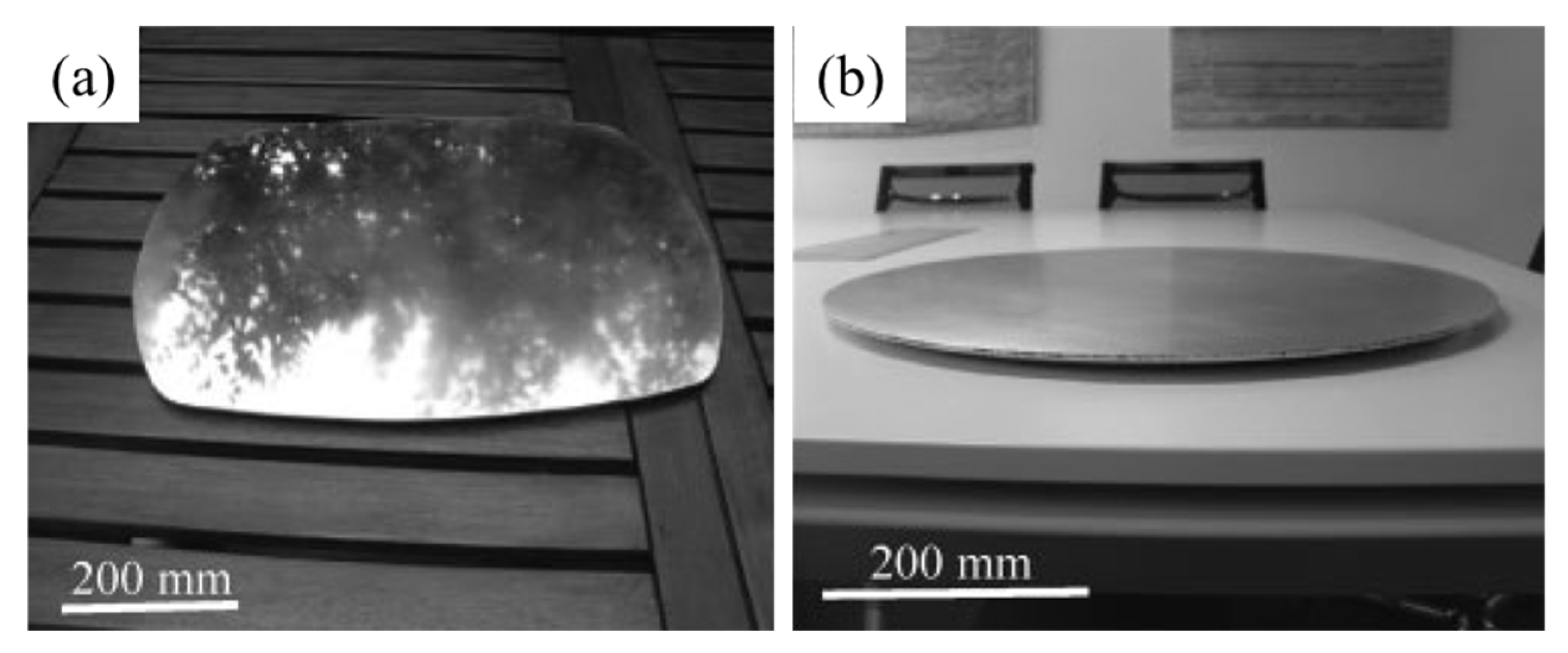
- The main fabrication methods of aluminum foams are the MF method, GIF method, and PMF method, and all these methods have been used in commercial production. The MF method is suitable for the fabrication of large-size blocks; the GIF method is suitable for the continuous production of foam slabs; and the PMF method is suitable for the fabrication of shaped parts or composite structures. Extensive research has led to the precise control of aluminum foam pore structure, enabling the production of foams with small pore sizes, uniform structures, and excellent properties.
- (2)
- The processing techniques of aluminum foams are introduced. Although various processes have been reported, many of them have failed to achieve commercial production due to poor pore structure, high costs, low efficiency, or the difficulty of fabricating large-size products. The difficulties in processing seriously limit the application of aluminum foams, making it of great significance to develop practical processing techniques.
- (3)
- Aluminum foams are suitable for energy absorption and crash protection. When used for protection, it is not always the case that foams with higher strength have better energy absorption ability. The MEPs of aluminum foams are mainly influenced by their pore structure, cell wall defects, and cell wall microstructure. Control of pore structure has been realized while the cell wall microstructure is relatively less concerned. Currently, the MEPs of aluminum foams are not good enough and still have room for improvement.
- (4)
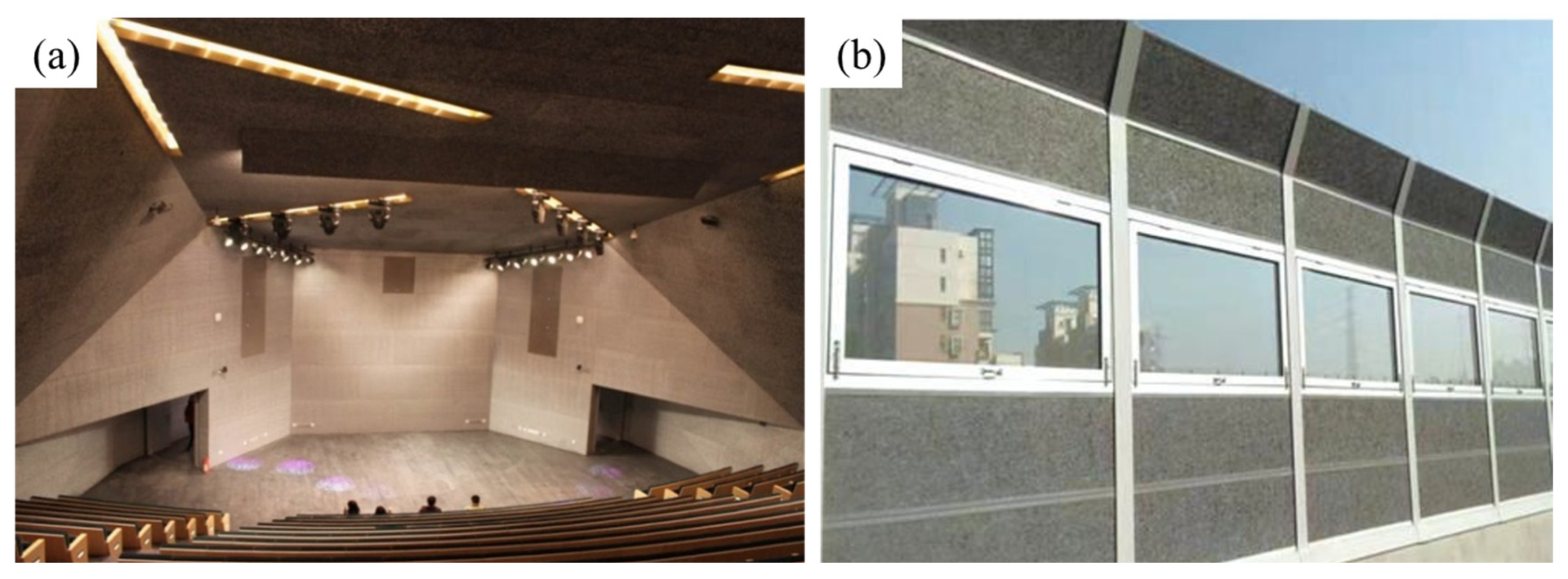
- In addition to MEPs, aluminum foams have many other unique characteristics including sound insulation, electromagnetic shielding, and heat resistance. They have been utilized in various fields including architecture, transportation, etc.
Author Contributions
Funding
Institutional Review Board Statement
Informed Consent Statement
Data Availability Statement
Conflicts of Interest
References
- Degischer, H.P.; Kriszt, B. Handbook of Cellular Metals: Production, Processing, Applications; Wiley-VCH: Weinheim, Germany, 2002. [Google Scholar]
- Evans, A.G.; Hutchinson, J.W.; Ashby, M.F. Multifunctionality of cellular metal systems. Prog. Mater. Sci. 1998, 43, 171–221. [Google Scholar] [CrossRef]
- Banhart, J. Light-Metal Foams—History of Innovation and Technological Challenges. Adv. Eng. Mater. 2013, 15, 82–111. [Google Scholar] [CrossRef]
- Goodall, R.; Mortensen, A. Porous metals. In Physical Metallurgy, 5th ed.; David, E.L., Kazuhiro, H., Eds.; Elsevier: Amsterdam, The Netherlands, 2014; Volume 3, pp. 2399–2595. [Google Scholar] [CrossRef]
- Atwater, M.A.; Guevara, L.N.; Darling, K.A.; Tschopp, M.A. Solid State Porous Metal Production: A Review of the Capabilities, Characteristics, and Challenges. Adv. Eng. Mater. 2018, 20, 1700766. [Google Scholar] [CrossRef]
- Singh, S.; Bhatnagar, N. A survey of fabrication and application of metallic foams (1925–2017). J. Porous Mater. 2018, 25, 537–554. [Google Scholar] [CrossRef]
- Singh, P.; Shakya, J.P.; Agarwal, P.; Jain, S.; Mondal, D.P.; Verma, K.S. Synthesis of Lightweight Metallic Foam and Their Applications in Various Engineering Sectors. In Advances in Processing of Lightweight Metal Alloys and Composites: Microstructural Characterization and Property Correlation; Vignesh, R.V., Padmanaban, R., Govindaraju, M., Eds.; Springer Nature: Singapore, 2023; pp. 51–74. [Google Scholar] [CrossRef]
- Banhart, J. Manufacture, characterisation and application of cellular metals and metal foams. Prog. Mater. Sci. 2001, 46, 559–632. [Google Scholar] [CrossRef]
- Dineshkumar, J.; Jesudas, T.; Elayaraja, R. Characteristics, applications and processing of aluminium foams—A Review. Mater. Today Proc. 2021, 42, 1773–1776. [Google Scholar] [CrossRef]
- Tripathi, O.; Singh, D.P.; Dwivedi, V.K.; Agarwal, M. A focused review on aluminum metallic foam: Processing, properties, and applications. Mater. Today Proc. 2021, 47, 6622–6627. [Google Scholar] [CrossRef]
- Garcia, M.F. Commercial Applications of Metal Foams: Their Properties and Production. Materials 2016, 9, 85. [Google Scholar] [CrossRef]
- Simone, A.E.; Gibson, L.J. Aluminum foams produced by liquid-state processes. Acta Mater. 1998, 46, 3109–3123. [Google Scholar] [CrossRef]
- Kodlibasanth, K.; Sunil, B.I.; Ali, S.; Yatika, G.; Abhishek, K.; Deepak, K.; Alok, J. Aluminum-foam by powder metallurgy: A review. Mater. Today Proc. 2023. [Google Scholar] [CrossRef]
- Kumar, N.; Bharti, A. Review on Powder Metallurgy: A Novel Technique for Recycling and Foaming of Aluminium-Based Materials. Powder Metall. Met. Ceram. 2021, 60, 52–59. [Google Scholar] [CrossRef]
- Nikunj, P.; Gaurav, M.; Mitushi, A.; Ajaya, K.P. Aluminum Foam Production, Properties, and Applications: A Review. Int. J. Met. 2023. [Google Scholar] [CrossRef]
- Lefebvre, L.P.; Banhart, J.; Dunand, D.C. Porous Metals and Metallic Foams: Current Status and Recent Developments. Adv. Eng. Mater. 2008, 10, 775–787. [Google Scholar] [CrossRef]
- Levine, B. A New Era in Porous Metals: Applications in Orthopaedics. Adv. Eng. Mater. 2008, 10, 788–792. [Google Scholar] [CrossRef]
- Inoue, A.; Kimura, H. High-strength aluminum alloys containing nanoquasicrystalline particles. Mater. Sci. Eng. A 2000, 286, 1–10. [Google Scholar] [CrossRef]
- Karuppasamy, R.; Debabrata, B. Production methods of aluminium foam: A brief review. Mater. Today Proc. 2021, 37, 1584–1587. [Google Scholar] [CrossRef]
- Kraenzlin, N.; Niederberger, M. Controlled fabrication of porous metals from the nanometer to the macroscopic scale. Mater. Horiz. 2015, 2, 359–377. [Google Scholar] [CrossRef]
- Lomte, A.; Sharma, B.; Drouin, M.; Schaffarzick, D. Sound absorption and transmission loss properties of open-celled aluminum foams with stepwise relative density gradients. Appl. Acoust. 2022, 193, 108780. [Google Scholar] [CrossRef]
- Wan, T.; Liu, Y.; Zhou, C.; Chen, X.; Li, Y. Fabrication, properties, and applications of open-cell aluminum foams: A review. J. Mater. Sci. Technol. 2021, 62, 11–24. [Google Scholar] [CrossRef]
- Banhart, J.; Vinod, K.G.; Kamm, P.H.; Neu, T.R.; García, M.F. Light-metal foams: Some recent developments. Ciência Tecnol. Mater. 2016, 28, 1–4. [Google Scholar] [CrossRef]
- Parveez, B.; Jamal, N.A.; Anuar, H.; Ahmad, Y.; Aabid, A.; Baig, M. Microstructure and Mechanical Properties of Metal Foams Fabricated via Melt Foaming and Powder Metallurgy Technique: A Review. Materials 2022, 15, 5302. [Google Scholar] [CrossRef] [PubMed]
- Kulshreshtha, A.; Dhakad, S.K. Preparation of metal foam by different methods: A review. Mater. Today Proc. 2020, 26, 1784–1790. [Google Scholar] [CrossRef]
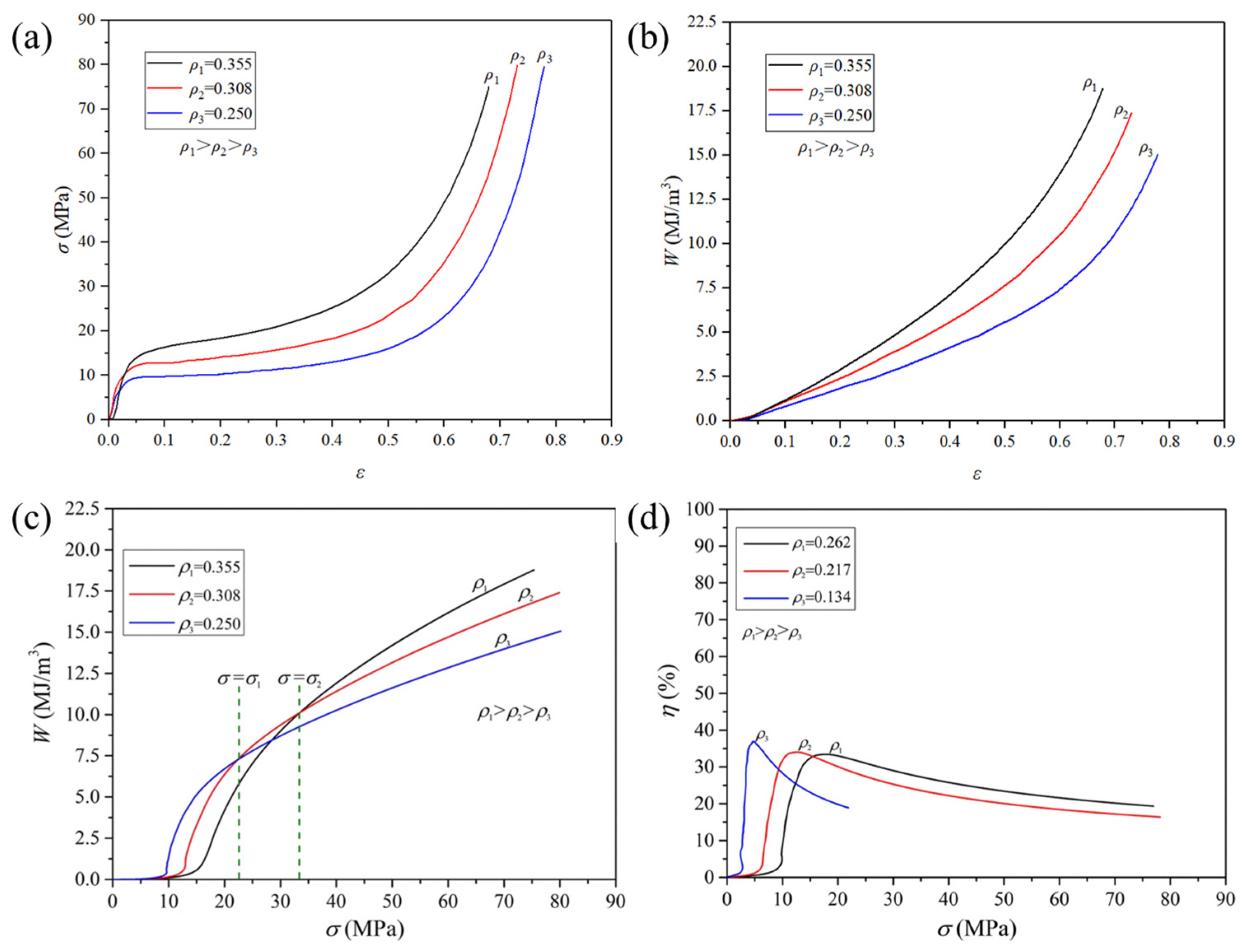
- Cheng, Y.; Li, Y.; Chen, X.; Zhou, X.; Wang, N. Compressive Properties and Energy Absorption of Aluminum Foams with a Wide Range of Relative Densities. J. Mater. Eng. Perform. 2018, 27, 4016–4024. [Google Scholar] [CrossRef]
- Zhou, X. Foaming Agent, Foaming Process and Compressive Properties of Aluminum Foam with Small Pore Size; Tsinghua University: Beijing, China, 2021. [Google Scholar]
- Sang, Y.K.; Soo, H.P.; Yong, S.U.; Bo, Y.H. Sound Absorption Properties of Al Foam. Mater. Sci. Forum 2005, 486, 468–471. [Google Scholar] [CrossRef]
- Feng, Y.; Zheng, H.; Zhu, Z.; Tao, N. Electromagnetic shielding effectiveness of closed-cell aluminum alloy foams. Chin. J. Nonferrous Met. 2004, 14, 33–36. [Google Scholar] [CrossRef]
- Zhu, X.; Ai, S.; Lu, X.; Ling, X.; Zhu, L.; Liu, B. Thermal conductivity of closed-cell aluminum foam based on the 3D geometrical reconstruction. Int. J. Heat Mass Transf. 2014, 72, 242–249. [Google Scholar] [CrossRef]
- Ito, K.; Kobayashi, H. Production and fabrication technology development of aluminum useful for automobile lightweighting. Adv. Eng. Mater. 2006, 8, 828–835. [Google Scholar] [CrossRef]
- Banhart, J.; Seeliger, H.W. Aluminium Foam Sandwich Panels: Manufacture, Metallurgy and Applications. Adv. Eng. Mater. 2008, 10, 793–802. [Google Scholar] [CrossRef]
- Cheng, Y.; Li, Y.; Chen, X.; Shi, T.; Liu, Z.; Wang, N. Fabrication of Aluminum Foams with Small Pore Size by Melt Foaming Method. Metall. Mater. Trans. B 2017, 48, 754–762. [Google Scholar] [CrossRef]
- Matz, A.M.; Mocker, B.S.; Mueller, D.W.; Jost, N.; Eggeler, G. Mesostructural Design and Manufacturing of Open-Pore Metal Foams by Investment Casting. Adv. Mater. Sci. Eng. 2014, 2014, 421729. [Google Scholar] [CrossRef]
- Goodall, R.; Marmottant, A.; Salvo, L.; Mortensen, A. Spherical pore replicated microcellular aluminium: Processing and influence on properties. Mater. Sci. Eng. A 2007, 465, 124–135. [Google Scholar] [CrossRef]
- Miyoshi, T.; Itoh, M.; Akiyama, S.; Kitahara, A. ALPORAS aluminum foam: Production process, properties, and applications. Adv. Eng. Mater. 2000, 2, 179–183. [Google Scholar] [CrossRef]
- Kalauni, K.; Pawar, S.J. A review on the taxonomy, factors associated with sound absorption and theoretical modeling of porous sound absorbing materials. J. Porous Mater. 2019, 26, 1795–1819. [Google Scholar] [CrossRef]
- Farhadi, S.; Dorsa, K.; Shervin, Z. Review of aluminum foam applications in architecture. Eur. J. Eng. Sci. Technol. 2020, 3, 62–70. [Google Scholar] [CrossRef]
- Bhogi, S.; Mukherjee, M. Foam stabilization by magnesium. Mater. Lett. 2017, 200, 118–120. [Google Scholar] [CrossRef]
- Mondal, D.P.; Goel, M.D.; Das, S. Compressive deformation and energy absorption characteristics of closed cell aluminum-fly ash particle composite foam. Mater. Sci. Eng. A 2009, 507, 102–109. [Google Scholar] [CrossRef]
- Gergely, V.; Clyne, B. The FORMGRIP process: Foaming of reinforced metals by gas release in precursors. Adv. Eng. Mater. 2000, 2, 175–178. [Google Scholar] [CrossRef]
- Sasikumar, S.; Georgy, K.; Mukherjee, M.; Kumar, G.S.V. Foam stabilization by aluminum powder. Mater. Lett. 2020, 262, 127142. [Google Scholar] [CrossRef]
- Han, F.S.; Wei, J.N.; Cheng, H.F.; Gao, J.C. Effects of process parameters and alloy compositions on the pore structure of foamed aluminum. J. Mater. Process. Technol. 2003, 138, 505–507. [Google Scholar] [CrossRef]
- Song, Z.L.; Ma, L.Q.; Wu, Z.J.; He, D.P. Effects of viscosity on cellular structure of foamed aluminum in foaming process. J. Mater. Sci. 2000, 35, 15–20. [Google Scholar] [CrossRef]
- Li, D.W.; Sun, T.; Yao, G.C.; Zhang, X.M.; Li, J. Preparation of foam aluminum with small pores by melt-based route of ZrH2. Chin. J. Nonferrous Met. 2010, 20, 143–148. [Google Scholar] [CrossRef]
- Papadopoulos, D.P.; Omar, H.; Stergioudi, F.; Tsipas, S.A.; Lefakis, H.; Michailidis, N. A novel method for producing Al-foams and evaluation of their compression behavior. J. Porous Mater. 2010, 17, 773–777. [Google Scholar] [CrossRef]
- Bhosle, V.; Baburaj, E.; Miranova, M.; Salama, K. Dehydrogenation of TiH2. Mater. Sci. Eng. A 2003, 356, 190–199. [Google Scholar] [CrossRef]
- Jimenez, C.; Garcia, M.F.; Rack, A.; Tucoulou, R.; Klaus, M.; Pfretzschner, B.; Rack, T.; Cloetens, P.; Banhart, J. Partial decomposition of TiH2 studied in situ by energy-dispersive diffraction and ex situ by diffraction microtomography of hard X-ray synchrotron radiation. Scr. Mater. 2012, 66, 757–760. [Google Scholar] [CrossRef]
- Matijasevic, L.B.; Banhart, J.; Fiechter, S.; Görke, O.; Wanderka, N. Modification of titanium hydride for improved aluminium foam manufacture. Acta Mater. 2006, 54, 1887–1900. [Google Scholar] [CrossRef]
- Jimenez, C.; Garcia, M.F.; Pfretzschner, B.; Klaus, M.; Wollgarten, M.; Zizak, I.; Schumacher, G.; Tovar, M.; Banhart, J. Decomposition of TiH2 studied in situ by synchrotron X-ray and neutron diffraction. Acta Mater. 2011, 59, 6318–6330. [Google Scholar] [CrossRef]
- Romero, R.M.; Domínguez, R.C.; Torres, S.R.; Aguilar, E.A. Core/multi-shell particles based on TiH2, a high-performance thermally activated foaming agent. Mater. Chem. Phys. 2020, 243, 122591. [Google Scholar] [CrossRef]
- Yuan, W.; Chen, X.; Liu, Y.; Li, Y. Research on key technologies for batch preparation of aluminum foam slabs by melt foaming process. Rare Met. Mater. Eng. 2009, 38, 306–310. [Google Scholar]
- Zuo, X.; Kennedy, A.R.; Wang, Y.; Bi, Y.; Lu, J.; Zhou, Y. Fabrication and compressive properties of Al foam with fine cell structure. Rare Met. Mater. Eng. 2009, 38, 255–259. [Google Scholar]
- Cao, Z.; Li, M.; Yu, Y.; Luo, H. Fabrication of Aluminum Foams with Fine Cell Structure under Increased Pressure. Adv. Eng. Mater. 2016, 18, 1022–1026. [Google Scholar] [CrossRef]
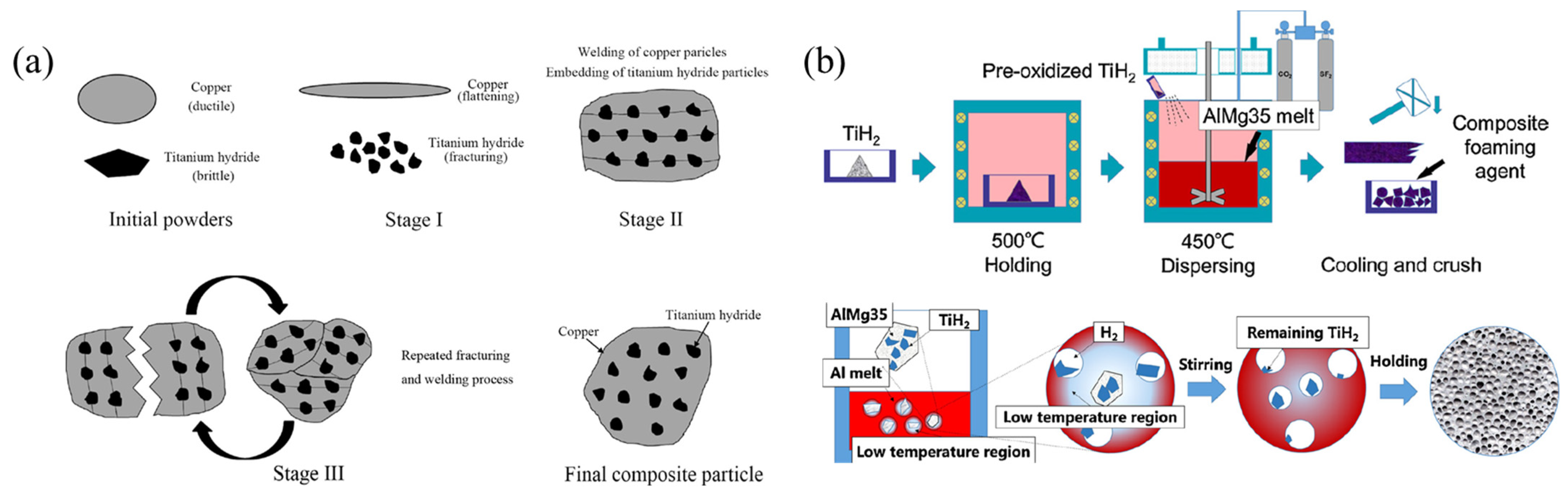
- Zhou, X.; Li, Y.; Chen, X. Development of AlMg35-TiH2 composite foaming agent and fabrication of small pore size aluminium foams. J. Mater. Process. Technol. 2020, 283, 116698. [Google Scholar] [CrossRef]
- Leitlmeier, D.; Degischer, H.P.; Flankl, H. Development of a foaming process for particulate reinforced aluminum melts. Adv. Eng. Mater. 2002, 4, 735–740. [Google Scholar] [CrossRef]
- Wang, N.; Maire, E.; Chen, X.; Adrien, J.; Li, Y.; Amani, Y.; Hu, L.; Cheng, Y. Compressive performance and deformation mechanism of the dynamic gas injection aluminum foams. Mater. Charact. 2019, 147, 11–20. [Google Scholar] [CrossRef]
- Babcsán, N.; Beke, S.; Makk, P.; Soki, P.; Számel, G.; Degischer, H.P.; Mokso, R. ALUHAB—The Superior Aluminium Foam. In Proceedings of the 13th International Conference on Aluminum Alloys, Pittsburgh, PA, USA, 3–7 June 2012. [Google Scholar] [CrossRef]
- Noack, M.A.; Buelk, F.; Wang, N.; Banhart, J.; Garcia, M.F. Aluminium foam with sub-mm sized cells produced using a rotating gas injector. Mater. Sci. Eng. B 2021, 273, 115427. [Google Scholar] [CrossRef]
- Yuan, J.; Li, Y. Effect of orifice geometry on bubble formation in melt gas injection to prepare aluminum foams. Sci. China Technol. Sci. 2015, 58, 64–74. [Google Scholar] [CrossRef]
- Babcsán, N.; Leitlmeier, D.; Degischer, H.P. Foamability of particle reinforced aluminum melt. Materialwiss. Werkstofftech. 2003, 34, 22–29. [Google Scholar] [CrossRef]
- Babcsán, N.; Leitlmeier, D.; Degischer, H.P.; Banhart, J. The role of oxidation in blowing particle-stabilised aluminium foams. Adv. Eng. Mater. 2004, 6, 421–428. [Google Scholar] [CrossRef]
- Heim, K.; Vinod, K.G.; Garcia, M.F.; Rack, A.; Banhart, J. Stabilisation of aluminium foams and films by the joint action of dispersed particles and oxide films. Acta Mater. 2015, 99, 313–324. [Google Scholar] [CrossRef]
- Zhou, Y.; Li, Y. Oxide film on bubble surface of aluminum foams produced by gas injection foaming process. Trans. Nonferrous Met. Soc. China 2015, 25, 2429–2437. [Google Scholar] [CrossRef]
- Zhou, Y.; Li, Y.; Yuan, J. The stability of aluminum foams at accumulation and condensation stages in gas injection foaming process. Colloids Surf. A 2015, 482, 468–476. [Google Scholar] [CrossRef]
- Ip, S.W.; Wang, S.W.; Toguri, J.M. Aluminum foam stabilization by solid particles. Can. Metall. Q. 1999, 38, 81–92. [Google Scholar] [CrossRef]
- Liu, X.N.; Li, Y.X.; Chen, X.; Liu, Y.; Fan, X.L. Foam stability in gas injection foaming process. J. Mater. Sci. 2010, 45, 6481–6493. [Google Scholar] [CrossRef]
- Heim, K.; Vinod, K.G.; Garcia, M.F.; Banhart, J. Stability of various particle-stabilised aluminium alloys foams made by gas injection. J. Mater. Sci. 2017, 52, 6401–6414. [Google Scholar] [CrossRef]
- Heim, K.; Garcia, M.F.; Banhart, J. Particle size and fraction required to stabilise aluminium alloy foams created by gas injection. Scr. Mater. 2018, 153, 54–58. [Google Scholar] [CrossRef]
- Liu, X.; Li, Y.; Chen, X. Bubble size control during the gas injection foaming process in aluminum alloy melt. J. Mater. Res. 2015, 30, 1002–1010. [Google Scholar] [CrossRef]
- Yuan, J.; Li, Y.; Wang, N.; Cheng, Y.; Chen, X. Effect of Orifice Diameter on Bubble Generation Process in Melt Gas Injection to Prepare Aluminum Foams. Metall. Mater. Trans. B 2016, 47, 1649–1660. [Google Scholar] [CrossRef]
- Sano, M.; Mori, K. Bubble Formation from Single Nozzles in Liquid Metals. Trans. Jpn. Inst. Met. 1976, 17, 344–352. [Google Scholar] [CrossRef]
- Yuan, J.; Li, Y.; Zhou, Y. Effect of contact angle on bubble formation at submerged orifices. J. Mater. Sci. 2014, 49, 8084–8094. [Google Scholar] [CrossRef]
- Wang, N.; Chen, X.; Li, Y.; Liu, Z.; Zhao, Z.; Cheng, Y.; Liu, Y.; Zhang, H. The cell size reduction of aluminum foam with dynamic gas injection based on the improved foamable melt. Colloids Surf. A 2017, 527, 123–131. [Google Scholar] [CrossRef]
- Wang, N.; Chen, X.; Yuan, J.; Wang, G.; Li, Y.; Zhang, H.; Liu, Y. Bubble Formation at a Submerged Orifice in High-Speed Horizontal Oscillation. Metall. Mater. Trans. B 2016, 47, 3362–3374. [Google Scholar] [CrossRef]
- Zhou, Y.; Li, Y.; Yuan, J. The influence of pure Al and hypoeutectic Al-Si alloy base materials on the cell structures of aluminum foams produced by gas injection foaming process. J. Funct. Mater. 2015, 46, 10941–10945. [Google Scholar]
- Baumgärtner, F.; Duarte, I.; Banhart, J. Industrialization of powder compact foaming process. Adv. Eng. Mater. 2000, 2, 168–174. [Google Scholar] [CrossRef]
- Duarte, I.; Vesenjak, M.; Vide, M.J. Automated continuous production line of parts made of metallic foams. Metals 2019, 9, 531. [Google Scholar] [CrossRef]
- Banhart, J.; Seeliger, H.W. Recent trends in aluminum foam sandwich technology. Adv. Eng. Mater. 2012, 14, 1082–1087. [Google Scholar] [CrossRef]
- Schäffler, P.; Rajner, W. Process stability in serial production of aluminium foam panels and 3D parts. Adv. Eng. Mater. 2004, 6, 452–453. [Google Scholar] [CrossRef]
- Banhart, J. Metal Foams: Production and Stability. Adv. Eng. Mater. 2006, 8, 781–794. [Google Scholar] [CrossRef]
- Kuntz, D.; Baumeister, J.; Banhart, J. PM technology in the production of metal foams. Int. J. Powder Metall. 1994, 25, 182–185. [Google Scholar]
- Ding, X.; Liu, Y.; Wan, T. A novel hot-pressing method to prepare foamable precursor of aluminum foam sandwich (AFS). Mater. Lett. 2020, 259, 126895. [Google Scholar] [CrossRef]
- Duarte, I.; Banhart, J. A study of aluminium foam formation—Kinetics and microstructure. Acta Mater. 2000, 48, 2349–2362. [Google Scholar] [CrossRef]
- Banhart, J.; Baumeister, J. Deformation characteristics of metal foams. J. Mater. Sci. 1998, 33, 1431–1440. [Google Scholar] [CrossRef]
- Lehmhus, D.; Banhart, J.; Rodriguez-Perez, M.A. Adaptation of aluminum foam properties by means of precipitation hardening. Mater. Sci. Technol. 2002, 18, 474–479. [Google Scholar] [CrossRef]
- Aguirre, P.L.; Jung, I.H.; Drew, R.A. Foaming behavior of powder metallurgical Al-Sn foams. Acta Mater. 2012, 60, 759–769. [Google Scholar] [CrossRef]
- Ding, X.; Peng, B.; Hu, X.; Pan, K.; Liu, Y.; Wan, T.; Ran, S. Effect of Cu and Sn additions on the cellular structure of Al-Si-Mg alloys foaming at low temperature (≤600 °C). Compos. Part B 2022, 234, 109693. [Google Scholar] [CrossRef]
- Koizumi, T.; Kido, K.; Kita, K.; Mikado, K.; Gnyloskurenko, S.; Nakamura, T. Foaming agents for powder metallurgy production of aluminum foam. Mater. Trans. 2011, 52, 728–733. [Google Scholar] [CrossRef]
- Bisht, A.; Gangil, B.E.; Patel, V.K. Selection of blowing agent for metal foam production: A review. J. Met. Mater. Miner. 2020, 30, 1–10. [Google Scholar] [CrossRef]
- Barode, J.; Aravind, U.; Bhogi, S.; Muduli, B.; Mukherjee, M. Mg and Mg-Based Blowing Agents for Aluminum Foam. Metall. Mater. Trans. B 2021, 52, 292–304. [Google Scholar] [CrossRef]
- Kamm, P.H.; García, M.F.; Jiménez, C.; Banhart, J. Suitability of various complex hydrides for foaming aluminum alloys. J. Mater. Res. 2013, 28, 2436–2443. [Google Scholar] [CrossRef]
- Ding, X.; Liu, Y.; Chen, X.; Zhang, H.; Li, Y. Optimization of cellular structure of aluminum foams produced by powder metallurgy method. Mater. Lett. 2018, 216, 38–41. [Google Scholar] [CrossRef]
- Neu, T.R.; Pfretzschner, B.; García-Moreno, F.; Banhart, J. Influence of the heating rate on the foaming behavior of various aluminum alloys. Metals 2017, 7, 323. [Google Scholar] [CrossRef]
- Behymer, N.; Morsi, K. Closed-Cell Metallic Foams Produced via Powder Metallurgy. Metals 2023, 13, 959. [Google Scholar] [CrossRef]
- Mukherjee, M.; Ramamurty, U.; Garcia, M.F.; Banhart, J. The effect of cooling rate on the structure and properties of closed-cell aluminum foams. Acta Mater. 2010, 58, 5031–5042. [Google Scholar] [CrossRef]
- Kamm, P.H.; Neu, T.R.; Garcia, M.F.; Banhart, J. Nucleation and growth of gas bubbles in AlSi8Mg4 foam investigated by X-ray tomoscopy. Acta Mater. 2021, 206, 116583. [Google Scholar] [CrossRef]
- Rack, A.; Helwig, H.M.; Buetow, A.; Rueda, A.; Matijasevic, L.B.; Helfen, L.; Goebbels, J.; Banhart, J. Early pore formation in aluminium foams studied by synchrotron-based microtomography and 3-D image analysis. Acta Mater. 2009, 57, 4809–4821. [Google Scholar] [CrossRef]
- Kamm, P.H.; Garcia, M.F.; Neu, T.R.; Heim, K.; Mokso, R.; Banhart, J. Fast Synchrotron X-Ray Tomography of Dynamic Processes in Liquid Aluminium Alloy Foam. Adv. Eng. Mater. 2017, 19, 1600550. [Google Scholar] [CrossRef]
- Garcia, M.F.; Kamm, P.H.; Neu, T.R.; Buelk, F.; Mokso, R.; Schleputz, C.M.; Stampanoni, M.; Banhart, J. Using X-ray tomoscopy to explore the dynamics of foaming metal. Nat. Commun. 2019, 10, 3762. [Google Scholar] [CrossRef]
- Garcia, M.F.; Juergens, M.; Banhart, J. Temperature dependence of film rupture and internal structural stability in liquid aluminium alloy foams. Acta Mater. 2020, 196, 325–337. [Google Scholar] [CrossRef]
- Mukherjee, M.; Garcia, M.F.; Banhart, J. Solidification of metal foams. Acta Mater. 2010, 58, 6358–6370. [Google Scholar] [CrossRef]
- Garcia, M.F.; Solorzano, E.; Banhart, J. Kinetics of coalescence in liquid aluminium foams. Soft Matter 2011, 7, 9216–9223. [Google Scholar] [CrossRef]
- Yuan, G.; Li, Y.; Hu, L.; Fu, W. Preparation of shaped aluminum foam parts by investment casting. J. Mater. Process. Technol. 2023, 314, 117897. [Google Scholar] [CrossRef]
- Körner, C.; Hirschmann, M.; Wiehler, H. Integral Foam Moulding of Light Metals. Mater. Trans. 2006, 47, 2188–2194. [Google Scholar] [CrossRef]
- Nowacki, J.; Moraniec, K. Welding of metallic AlSi foams and AlSi-SiC composite foams. Arch. Civ. Mech. Eng. 2015, 15, 940–950. [Google Scholar] [CrossRef]
- Duarte, I.; Oliveira, M.; Garcia-Moreno, F.; Mukherjee, M.; Banhart, J. Foaming of AA 6061 using multiple pieces of foamable precursor. Colloids Surf. A 2013, 438, 47–55. [Google Scholar] [CrossRef]
- Shang, J.T.; Chu, X.; He, D. Preparation of three-dimensional shaped aluminum alloy foam by two-step foaming. Mater. Sci. Eng. B 2008, 151, 157–162. [Google Scholar] [CrossRef]
- Wang, H.; Zhang, Y.M.; Zhou, B.C.; Yang, D.H.; Wu, Y.; Liu, X.J.; Lu, Z.P. Mold-Filling Ability of Aluminum Alloy Melt during the Two-Step Foaming Process. J. Mater. Sci. Technol. 2016, 32, 509–514. [Google Scholar] [CrossRef]
- Cingi, C.; Niini, E.; Orkas, J. Foamed aluminum parts by investment casting. Colloids Surf. A 2009, 344, 113–117. [Google Scholar] [CrossRef]
- Babcsán, N.; Beke, S.; Makk, P.; Szamel, G.; Kadar, C. Pilot production and properties of ALUHAB aluminium foams. Procedia Mater. Sci. 2014, 4, 127–132. [Google Scholar] [CrossRef]
- Filice, L.; Gagliardi, F.; Shivpuri, R.; Umbrello, D. Experimental and Numerical Investigation of Forging Process to Reproduce a 3D Aluminum Foam Complex Shape. AIP Conf. Proc. 2007, 908, 1225–1230. [Google Scholar] [CrossRef]
- Zhang, X.; Chen, Q.M.; Cai, Z.Y. Prediction and prevention of fracture defect in plastic forming for aluminum foam sandwich panel. J. Mater. Res. Technol. 2021, 15, 1145–1154. [Google Scholar] [CrossRef]
- Liu, Z.; Cheng, Y.; Li, Y.; Zhou, X.; Chen, X.; Wang, N. Shape formation of closed-cell aluminum foam in solid-liquid-gas coexisting state. Int. J. Miner. Metall. Mater. 2018, 25, 974–980. [Google Scholar] [CrossRef]
- Körner, C. Integral Foam Molding of Light Metals; Springer: Erlangen, Germany, 2008. [Google Scholar] [CrossRef]
- Hartmann, J.; Trepper, A.; Koerner, C. Aluminum Integral Foams with Near-Microcellular Structure. Adv. Eng. Mater. 2011, 13, 1050–1055. [Google Scholar] [CrossRef]
- Hartmann, J.; Bluemel, C.; Ernst, S.; Fiegl, T.; Wirth, K.E.; Koerner, C. Aluminum integral foam castings with microcellular cores by nano-functionalization. J. Mater. Sci. 2014, 49, 79–87. [Google Scholar] [CrossRef]
- Claar, T.D.; Yu, C.J.; Hall, I.; Banhart, J.; Baumeister, J.; Weber, M.; Seeliger, W. Ultra-light-weight aluminum foam materials for automotive applications. J. Mater. Manuf. 2000, 36, 98–106. Available online: https://www.jstor.org/stable/44643817 (accessed on 21 January 2024).
- Xia, F.; Wu, X.; Liu, P. Methods for determining aperture of porous materials. Chin. J. Tissue Eng. Res. 2008, 12, 8184–8188. [Google Scholar]
- Li, Q.M.; Magkiriadis, I.; Harrigan, J.J. Compressive strain at the onset of densification of cellular solids. J. Cell. Plast. 2006, 42, 371–392. [Google Scholar] [CrossRef]
- Dannemann, K.A.; Lankford, J. High strain rate compression of closed-cell aluminium foams. Mater. Sci. Eng. A 2000, 293, 157–164. [Google Scholar] [CrossRef]
- Mukai, T.; Kanahashi, H.; Miyoshi, T.; Mabuchi, M.; Nieh, T.G.; Higashi, K. Experimental study of energy absorption in a close-celled aluminum foam under dynamic loading. Scr. Mater. 1999, 40, 921–927. [Google Scholar] [CrossRef]
- Kader, M.A.; Hazell, P.J.; Islam, M.A.; Ahmed, S.; Hossain, M.M.; Escobedo, J.P.; Saadatfar, M. Strain-rate dependency and impact dynamics of closed-cell aluminium foams. Mater. Sci. Eng. A 2021, 818, 141379. [Google Scholar] [CrossRef]
- Sadot, O.; Ram, O.; Anteby, I.; Gruntman, S.; Ben, D.G. The trapped gas effect on the dynamic compressive strength of light aluminum foams. Mater. Sci. Eng. A 2016, 659, 278–286. [Google Scholar] [CrossRef]
- Sun, Y.; Li, Q.M. Dynamic compressive behavior of cellular materials: A review of phenomenon, mechanism and modelling. Int. J. Impact Eng. 2018, 112, 74–115. [Google Scholar] [CrossRef]
- Paul, A.; Ramamurty, U. Strain rate sensitivity of a closed-cell aluminum foam. Mater. Sci. Eng. A 2000, 281, 1–7. [Google Scholar] [CrossRef]
- Nisa, S.U.; Pandey, S.; Pandey, P.M. A review of the compressive properties of closed-cell aluminum metal foams. J. Process Mech. Eng. 2023, 237, 531–545. [Google Scholar] [CrossRef]
- Ramamurty, U.; Paul, A. Variability in mechanical properties of a metal foam. Acta Mater. 2004, 52, 869–876. [Google Scholar] [CrossRef]
- Insu, J.; Kiyotaka, K.; Tsutomu, S.; Tadashi, A.; Kiju, K. Cell wall mechanical properties of closed-cell Al foam. Mech. Mater. 2008, 41, 60–73. [Google Scholar] [CrossRef]
- Islam, M.A.; Kader, M.A.; Hazell, P.J.; Brown, A.D.; Saadatfar, M.; Quadir, M.Z.; Escobedo, J.P. Investigation of microstructural and mechanical properties of cell walls of closed-cell aluminium alloy foams. Mater. Sci. Eng. A 2016, 666, 245–256. [Google Scholar] [CrossRef]
- Ulbin, M.; Vesenjak, M.; Borovinšek, M.; Duarte, I.; Higa, Y.; Shimojima, K.; Ren, Z. Detailed Analysis of Closed-Cell Aluminum Alloy Foam Internal Structure Changes during Compressive Deformation. Adv. Eng. Mater. 2018, 20, 1800164. [Google Scholar] [CrossRef]
- Farahani, M.R.; Ashtiani, H.R.; Elahi, S. Effect of Intermetallic Phases and Compounds on the Compressive Behavior and Fracture Mechanism of Al-Si-Zn Foams. Int. J. Met. 2023, 18, 403–416. [Google Scholar] [CrossRef]
- Amsterdam, E.; Th, M.J.; De, H.; Onck, P.R. Failure mechanisms of closed-cell aluminum foam under monotonic and cyclic loading. Acta Mater. 2006, 54, 4465–4472. [Google Scholar] [CrossRef]
- Yang, D.H.; Yang, S.R.; Ma, A.B.; Jiang, J.H. Compression properties of cellular AlCu5Mn alloy foams with wide range of porosity. J. Mater. Sci. 2009, 44, 5552–5556. [Google Scholar] [CrossRef]
- Sugimura, Y.; Meyer, J.; He, M.Y.; BartSmith, H.; Grenstedt, J.; Evans, A.G. On the mechanical performance of closed cell Al alloy foams. Acta Mater. 1997, 45, 5245–5259. [Google Scholar] [CrossRef]
- Mukherjee, M.; Garcia, M.F.; Jimenez, C.; Rack, A.; Banhart, J. Microporosity in aluminum foams. Acta Mater. 2017, 131, 156–168. [Google Scholar] [CrossRef]
- Wang, N.; Maire, E.; Cheng, Y.; Amani, Y.; Li, Y.; Adrien, J.; Chen, X. Comparison of aluminium foams prepared by different methods using X-ray tomography. Mater. Charact. 2018, 138, 296–307. [Google Scholar] [CrossRef]
- Lazaro, J.; Solorzano, E.; Rodriguez, P.M.; Kennedy, A.R. Effect of solidification rate on pore connectivity of aluminium foams and its consequences on mechanical properties. Mater. Sci. Eng. A 2016, 672, 236–246. [Google Scholar] [CrossRef]
- Hu, L. Study on Solidification Microstructure, Defects and Compressive Properties of Aluminum Foams; Tsinghua University: Beijing, China, 2022. [Google Scholar]
- Markaki, A.E.; Clyne, T.W. The effect of cell wall microstructure on the deformation and fracture of aluminium-based foams. Acta Mater. 2001, 49, 1677–1686. [Google Scholar] [CrossRef]
- Shi, T.; Chen, X.; Cheng, Y.; Liu, Y.; Zhang, H.; Li, Y. Microstructure and Compressive Properties of Aluminum Foams Made by 6063 Aluminum Alloy and Pure Aluminum. Mater. Trans. 2018, 59, 625–633. [Google Scholar] [CrossRef]
- Huang, L.; Wang, H.; Yang, D.; Ye, F.; Lu, Z.P. Effects of scandium additions on mechanical properties of cellular Al-based foams. Intermetallics 2012, 28, 71–76. [Google Scholar] [CrossRef]
- Verma, K.S.; Muchhala, D.; Panthi, S.; Mondal, D.P. Experimental and Numerical Study of Compressive Deformation Behavior of Closed-Cell Aluminum Foam. Strength Mater. 2020, 52, 451–457. [Google Scholar] [CrossRef]
- Hu, L.; Li, Y.; Yuan, G.; Zhang, H. Solidification microstructure and grain refinement of closed-cell aluminum foams. J. Mater. Sci. 2022, 57, 11347–11364. [Google Scholar] [CrossRef]
- Huang, L.; Wang, H.; Yang, D.H.; Ye, F.; Wang, S.Q.; Lu, Z.P. Effects of calcium on mechanical properties of cellular Al-Cu foams. Mater. Sci. Eng. A 2014, 618, 471–478. [Google Scholar] [CrossRef]
- Xia, X.; Feng, H.; Zhang, X.; Zhao, W. The compressive properties of closed-cell aluminum foams with different Mn additions. Mater. Des. 2013, 51, 797–802. [Google Scholar] [CrossRef]
- Farahani, M.R.; Ashtiani, H.R.; Elahi, S.H. Effect of Zinc Content on the Mechanical Properties of Closed-Cell Aluminum Foams. Int. J. Met. 2022, 16, 713–722. [Google Scholar] [CrossRef]
- Lehmhus, D.; Banhart, J. Properties of heat-treated aluminium foams. Mater. Sci. Eng. A 2003, 349, 98–110. [Google Scholar] [CrossRef]
- Georgy, K.; Banerjee, P.; Mukherjee, M. The effect of heat treatment on the compression property of Al-Si-Mg foams produced using Mg blowing agent. Mater. Today Commun. 2023, 36, 106445. [Google Scholar] [CrossRef]
- An, Y.; Yang, S.; Wu, H.; Zhao, E.; Wang, Z. Investigating the internal structure and mechanical properties of graphene nanoflakes enhanced aluminum foam. Mater. Des. 2017, 134, 44–53. [Google Scholar] [CrossRef]
- Sinha, A.A.; Mondal, D.P.; Muchhala, D.; Khanna, S.K. Fabrication of Graphene-Reinforced Closed-Cell Aluminum Foam and Characterization at High Strain Rates. J. Mater. Eng. Perform. 2023, 32, 6248–6257. [Google Scholar] [CrossRef]
- Aldoshan, A.; Khanna, S. Effect of relative density on the dynamic compressive behavior of carbon nanotube reinforced aluminum foam. Mater. Sci. Eng. A 2017, 689, 17–24. [Google Scholar] [CrossRef]
- Gibson, L.J.; Ashby, M.F. Cellular Solids: Structure and Properties, 2nd ed.; Cambridge University Press: Cambridge, UK, 1997. [Google Scholar]
- Smyrnaios, E.; Tegos, C.; Stergioudi, F.; Maliaris, G.; Michailidis, N. Insights into building a digital twin of closed-cell aluminum foam during impact loading: Microstructural, experimental and finite element investigations. J. Mater. Res. Technol. 2023, 27, 2902–2911. [Google Scholar] [CrossRef]
- Zhuang, W.; Wang, E.; Zhang, H. Prediction of compressive mechanical properties of three-dimensional mesoscopic aluminium foam based on deep learning method. Mech. Mater. 2023, 182, 104684. [Google Scholar] [CrossRef]
- Simone, A.E.; Gibson, L.J. Effects of solid distribution on the stiffness and strength of metallic foams. Acta Mater. 1998, 46, 2139–2150. [Google Scholar] [CrossRef]
- Nix, W.D. Mechanical properties of thin films. Metall. Trans. A 1989, 20, 2217–2245. [Google Scholar] [CrossRef]
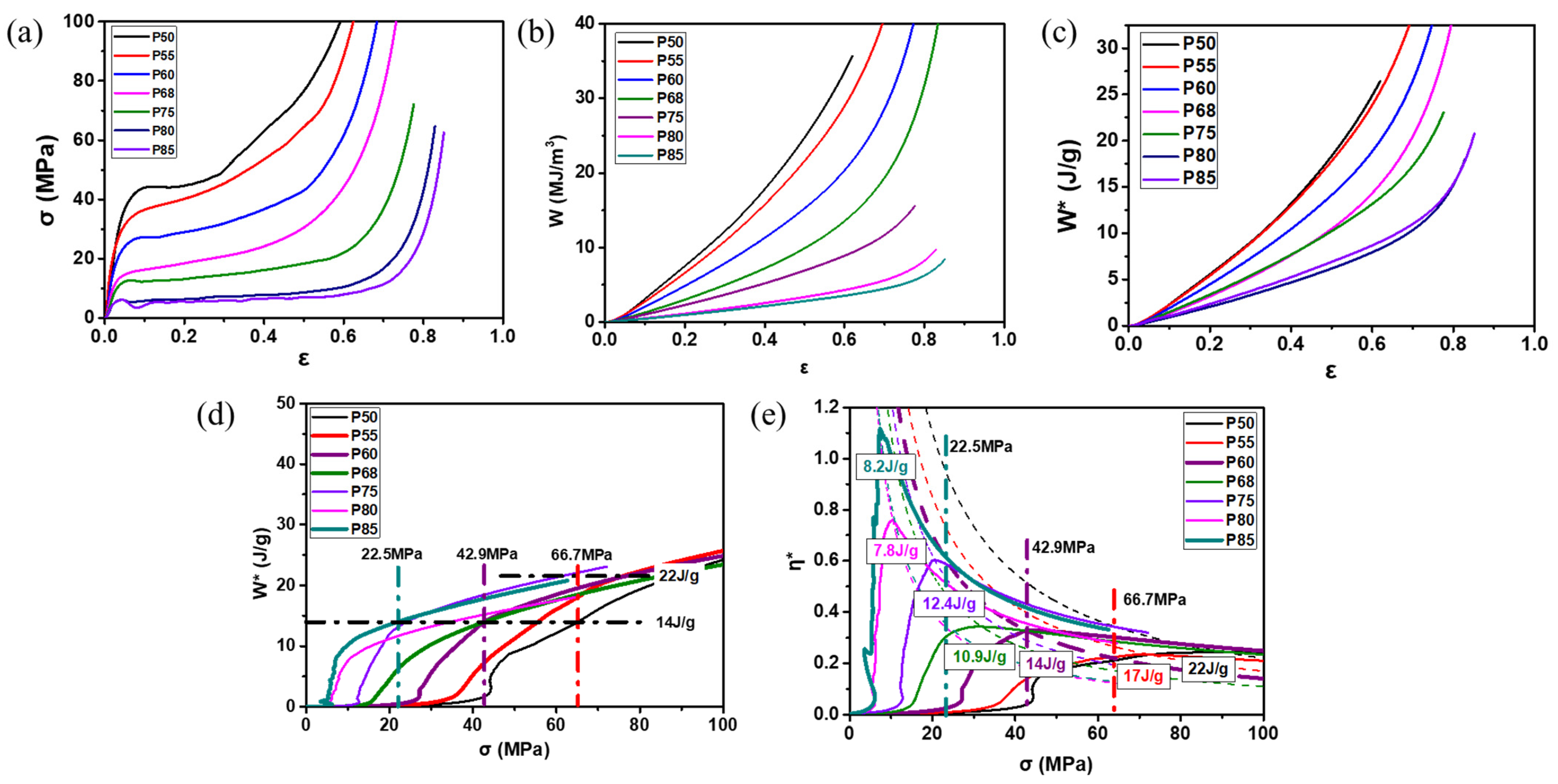
- Yang, X.; Xie, M.; Li, W.; Sha, J.; Zhao, N. Controllable Design of Structural and Mechanical Behaviors of Al-Si Foams by Powder Metallurgy Foaming. Adv. Eng. Mater. 2022, 24, 2200125. [Google Scholar] [CrossRef]
- Chen, X.; Wang, N.; Yuan, J.; Li, Y.; Zhang, H.; Yuan, L. Modeling of Macro-deformation Behavior of Thin-Walled Aluminum Foam by Gas Injection Method. J. Mater. Eng. Perform. 2017, 26, 3307–3318. [Google Scholar] [CrossRef]
- Zhao, W.; He, S.; Wei, X.; Du, Y.; Tang, G.; Zhang, Y.; Dai, G.; Gao, K.; Volkova, O. Quantitative relationships between cellular structure parameters and the elastic modulus of aluminum foam. Mater. Sci. Eng. A 2023, 868, 144713. [Google Scholar] [CrossRef]
- Ji, C.; Huang, H.; Wang, T.; Huang, Q. Recent advances and future trends in processing methods and characterization technologies of aluminum foam composite structures: A review. J. Manuf. Process. 2023, 93, 116–152. [Google Scholar] [CrossRef]
- Zhang, J.; An, Y.; Ma, H. Research Progress in the Preparation of Aluminum Foam Composite Structures. Metals 2022, 12, 2047. [Google Scholar] [CrossRef]
- Garai, F.; Beres, G.; Weltsch, Z. Development of tubes filled with aluminium foams for lightweight vehicle manufacturing. Mater. Sci. Eng. A 2020, 790, 139743. [Google Scholar] [CrossRef]
- Shyam, S.S.; Shravan, Y.; Anurag, J.; Ashish, G.; Rahul, K. Application of metallic foam in vehicle structure: A review. Mater. Today Proc. 2022, 63, 347–353. [Google Scholar] [CrossRef]
- Zhang, Y.; Pan, R.; Xiao, F. Numerical research on impact performance of bridge columns with aluminum foam protection devices. Int. J. Distrib. Sens. Netw. 2020, 16, 1550147720974538. [Google Scholar] [CrossRef]
- Pratomo, A.N.; Santosa, S.P.; Gunawan, L.; Widagdo, D.; Putra, I.S. Design optimization and structural integrity simulation of aluminum foam sandwich construction for armored vehicle protection. Compos. Struct. 2021, 276, 114461. [Google Scholar] [CrossRef]
- Li, Z.; Yu, Q.; Zhao, X.; Yu, M.; Shi, P.; Yan, C. Crashworthiness and lightweight optimization to applied multiple materials and foam-filled front end structure of auto-body. Adv. Mech. Eng. 2017, 9, 1–21. [Google Scholar] [CrossRef]
- Opiela, K.; Zielinski, T.; Dvorak, T.; Kúdela, J.S. Perforated closed-cell metal foam for acoustic applications. In Forum Acusticum; HAL: Lyon, France, 2020. [Google Scholar] [CrossRef]
- Lin, Z.; Gong, W.; Wan, L.; Shen, J.; Zhang, H.; Huang, J.; Zhu, B. Field Measurements for Traffic Noise Reduction in Highway Tunnels Using Closed-Cell Aluminum Foam Board. Appl. Sci. 2022, 12, 538. [Google Scholar] [CrossRef]
- Opiela, K.C.; Zielinski, T.G.; Dvorak, T.; Kudela, S. Perforated closed-cell aluminium foam for acoustic absorption. Appl. Acoust. 2021, 174, 107706. [Google Scholar] [CrossRef]
- Ko, Y.H.; Son, H.T.; Cho, J.I.; Kang, C.S.; Oh, I.H.; Lee, J.S.; Kim, H.M.; Kim, J.C. Investigation on the sound absorption and transmission for aluminum foam and its composite. Solid State Phenom. 2006, 124–126, 1825–1828. [Google Scholar] [CrossRef]
- Zou, T.; Hu, C.; Xie, M.; Cheng, Y. Research Development on Electromagnetic Shielding Property of Foam Metal. Hot Work. Technol. 2019, 48, 8–17. [Google Scholar] [CrossRef]
- Peng, H.K.; Wang, X.X.; Li, T.T.; Huang, S.Y.; Wu, L.W.; Lou, C.W.; Lin, J.H. Study on preparation, sound absorption, and electromagnetic shielding effectiveness of rigid foam composites. J. Sandw. Struct. Mater. 2019, 21, 2512–2526. [Google Scholar] [CrossRef]
- Xu, Z.; Hao, H. Electromagnetic interference shielding effectiveness of aluminum foams with different porosity. J. Alloys Compd. 2014, 617, 207–213. [Google Scholar] [CrossRef]
- Harshit, K.; Gupta, P. Advanced Research Developments and Commercialization of Light Weight Metallic Foams. In Handbook of Nanomaterials and Nanocomposites for Energy and Environmental Applications; Kharissova, O., Martínez, L., Kharisov, B., Eds.; Springer: Cham, Switzerland, 2020. [Google Scholar] [CrossRef]
- Solorzano, E.; Reglero, J.A.; Rodriguez, P.M.; Lehmhus, D.; Wichmann, M.; Saja, J.A. An experimental study on the thermal conductivity of aluminium foams by using the transient plane source method. Int. J. Heat Mass Transf. 2008, 51, 6259–6267. [Google Scholar] [CrossRef]


| Fabrication Methods | Pore Size | Porosity | Advantages | Disadvantages |
|---|---|---|---|---|
| MF | 1~8 mm | 50~90% | Fabrication of large-size blocks Low cost | Poor shaping ability |
| GIF | 1~25 mm | 75~98% | Simple process Continuous production Low cost | Difficult to disperse particles in the melt Blowing efficiency is low Pore size is large Poor mechanical properties |
| PMF | 1~6 mm | 50~90% | Near-net shape forming Fabrication of sandwich structures Metallurgical bonding between metal sheets | Pore structure control is difficult Large-size parts are difficult to make High cost |
Disclaimer/Publisher’s Note: The statements, opinions and data contained in all publications are solely those of the individual author(s) and contributor(s) and not of MDPI and/or the editor(s). MDPI and/or the editor(s) disclaim responsibility for any injury to people or property resulting from any ideas, methods, instructions or products referred to in the content. |
© 2024 by the authors. Licensee MDPI, Basel, Switzerland. This article is an open access article distributed under the terms and conditions of the Creative Commons Attribution (CC BY) license (https://creativecommons.org/licenses/by/4.0/).
Share and Cite
Fu, W.; Li, Y. Fabrication, Processing, Properties, and Applications of Closed-Cell Aluminum Foams: A Review. Materials 2024, 17, 560. https://doi.org/10.3390/ma17030560
Fu W, Li Y. Fabrication, Processing, Properties, and Applications of Closed-Cell Aluminum Foams: A Review. Materials. 2024; 17(3):560. https://doi.org/10.3390/ma17030560
Chicago/Turabian StyleFu, Wensheng, and Yanxiang Li. 2024. "Fabrication, Processing, Properties, and Applications of Closed-Cell Aluminum Foams: A Review" Materials 17, no. 3: 560. https://doi.org/10.3390/ma17030560
APA StyleFu, W., & Li, Y. (2024). Fabrication, Processing, Properties, and Applications of Closed-Cell Aluminum Foams: A Review. Materials, 17(3), 560. https://doi.org/10.3390/ma17030560