
Load Capacity of Screw Anchor Installed in Concrete Substrate Reinforced with Steel Fibers Depending on Fiber Content


Abstract
:1. Introduction
2. Materials
2.1. Steel Anchors

| No. | Type of Screw Anchor | Length L [mm] | Diameter d [mm] | Nut Diameter Sw [mm] |
|---|---|---|---|---|
| 1 | TFE14120 | 120 | 17 | 19 |
| 2 | TFE14140 | 140 | 17 | 19 |
2.2. Concrete Substrate
| Composition | SiO2 | Al2O3 | Fe2O3 | CaO | MgO | SO3 | Na2O | K2O | Cl | LOI | IR |
|---|---|---|---|---|---|---|---|---|---|---|---|
| Unit (vol.%) | 19.5 | 4.9 | 2.9 | 63.3 | 1.3 | 2.8 | 0.1 | 0.9 | 0.05 | 2.48 | 0.63 |
| Properties | Specific Surface Area [m2/kg] | Specific Gravity [kg/m3] | Compressive Strength [MPa] | |
|---|---|---|---|---|
| Material | After 2 Days | After 28 Days | ||
| Cement | 3840 | 3060 | 28.0 | 58.0 |
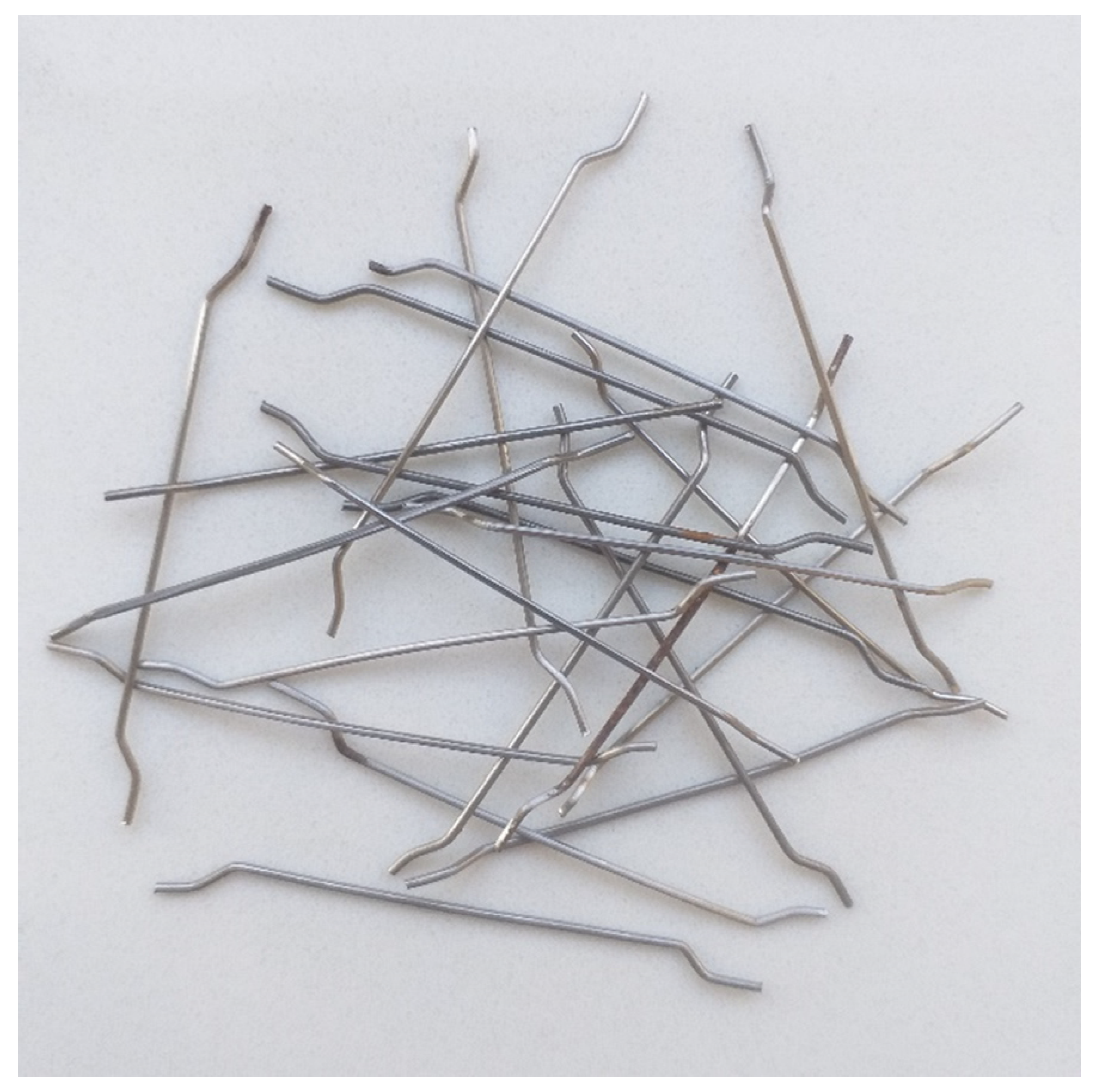
| Length of Fiber L [mm] | Length l [mm] | Diameter d [mm] | Height h [mm] | Tensile Strength Rm, min [MPa] |
|---|---|---|---|---|
| 50 | 4.0 | 0.75 | ≥3.0 | 100 |
3. Methodology
- -
- The HBM force and displacement measurement device was compatible with the force, displacement, and pressure transducers. Data processing software from Hbm QuantumX–Catman II, operating in Windows, was used;
- -
- C6 A force sensors (HBM, Darmstadt, Germany) were used in the range from 0 kN to 200 kN, with a force measurement resolution of 0.01 kN and a sensitivity of 2 mV/V;
- -
- WA50 displacement sensors (HBM, Darmstadt, Germany) were used in the range of 0–50 mm, with a resolution of 0.01 mm, as shown in Figure 5.
4. Results and Discussion
4.1. Mechanical Properties of the Concrete Substrate
4.2. The Results of the Pull-Out Test
5. Summary and Conclusions
- Steel fibers affect the destructive force of screw anchors, increasing the pull-out strength for each effective depth.
- A significant improvement in the value of the maximum destructive force was obtained for the concrete substrate with the addition of steel fiber.
- With increasing effective depth (effective depth (hef) = 45 mm–79 mm), the destructive force of screw anchors increases; this correlation is linear for screw anchors installed in concrete substrates without fiber and with the addition of fiber.
- To calculate the characteristic value of the load capacity of screw anchors in the fiber-reinforced concrete substrate with the addition of steel fiber, a kucr,N coefficient of 13.10 can be used. This was the lowest value obtained in this study for the load capacities of screw anchors in the fiber-reinforced concrete substrate.
Author Contributions
Funding
Institutional Review Board Statement
Informed Consent Statement
Data Availability Statement
Conflicts of Interest
References
- Dudek, D. Influence of Variable Loads of Expansion Fasteners on Their Load Capacity in Cracked Concrete Substrate. Ph.D. Thesis, Research Building Institute (ITB), Warsaw, Poland, 2017. [Google Scholar]
- EAD 330232-01-0601; Mechanical Fasteners for Use in Concrete. EOTA European Assessment Document: Brussels, Belgium, 2019.
- PN-EN 1992-4:2018-11; Eurocode 2: Design of Concrete Structures—Part 4: Design of Fasteners for Use in Concrete. PKN: Warsaw, Poland, 2018.
- Mahrenholtz, C.; Ayoubi, M.; Müller, S.; Bachschmid, S. Tension and shear performance of anchor channels with channel bolts cast in Fibre Reinforced Concrete (FRC). IOP Conf. Ser. Mater. Sci. Eng. 2019, 615, 012089. [Google Scholar] [CrossRef]
- Dudek, D.; Kadela, M. Pull-Out Strength of Resin Anchors in Non-cracked and Cracked Concrete and Masonry Substrates. Proc. Eng. 2016, 161, 864–867. [Google Scholar] [CrossRef]
- Schwenn, M.; Voit, K.; Zeman, O.; Bergmeister, K. Post-installed mechanical fasteners in high strength and ultra-high strength performance concrete. Civ. Eng. Des. 2019, 1, 161–167. [Google Scholar] [CrossRef]
- Ahmed, L.T.; Braimah, A. Behaviour of undercut anchors subjected to high strain rate loading. Proc. Eng. 2017, 210, 326–333. [Google Scholar] [CrossRef]
- Xu, X.; Tian, S. Load transfer mechanism and critical length of anchorage zone for anchor bolt. PLoS ONE 2010, 15, e0227539. [Google Scholar] [CrossRef] [PubMed]
- Woyciechowski, P.; Sokołowska, J.J.; Chondzyński, M. Influence of the condition of the concrete substrate on the steel fixing anchors load capacity. In Proceedings of Conference Dni Betonu; Stowarzyszenie Producentów Cementu: Wisła, Poland, 2018; pp. 207–221. Available online: https://www.dnibetonu.com/wp-content/pdfs/2018/woyciechowski_sokolowska_chondzynski.pdf (accessed on 9 December 2023).
- Małek, M.; Łasica, W.; Kadela, M.; Kluczyński, J.; Dudek, D. Physical and Mechanical Properties of Polypropylene Fibre-Reinforced Cement–Glass Composite. Materials 2021, 14, 637. [Google Scholar] [CrossRef] [PubMed]
- Gribniak, V.; Arnautov, A.; Norkus, A.; Kliukas, R.; Tamulenas, V.; Gudonis, E.; Sokolov, A. Steel Fibres: Effective Way to Prevent Failure of the Concrete Bonded with FRP Sheets. Adv. Mater. Sci. Eng. 2016, 2016, 4913536. [Google Scholar] [CrossRef]
- Bonopera, M.; Chang, K.-C.; Lin, T.-K.; Tullini, N. Influence of prestressing on the behavior of uncracked concrete beams with a parabolic bonded tendon. Struct. Eng. Mech. 2021, 77, 1–17. [Google Scholar] [CrossRef]
- Yang, J.-M.; Yoo, D.-Y.; Kim, Y.-C.; Yoon, Y.-S. Mechanical Properties of Steam Cured High-Strength Steel Fiber-Reinforced Concrete with High-Volume Blast Furnace Slag. Int. J. Concr. Struct. Mater. 2017, 11, 391–401. [Google Scholar] [CrossRef]
- Dudek, D.; Knap, P.; Kadela, M. Nośność łączników w podłożach betonowych zarysowanych wskutek oddziaływania eksploatacji górniczej. Bezpieczeństwo Pr. i Ochr. Sr. w Górnictwie 2015, 10, 23–27. [Google Scholar]
- Ruopp, J.; Kuhlmann, U. Steel-to-concrete joints with large anchor plates under shear loading. Steel Constr. 2017, 10, 115–124. [Google Scholar] [CrossRef]
- Luo, Y.; Wu, B. Shear performance of steel plate-concrete joints connected with anchors and adhesive. J. Adhes. 2020, 98, 889–914. [Google Scholar] [CrossRef]
- Panzera, T.H.; Christoforo, A.L.; Ribeiro Borges, P.H. 15—High performance fibre-reinforced concrete (FRC) for civil engineering applications. In Woodhead Publishing Series in Civil and Structural Engineering. Advanced Fibre-Reinforced Polymer (FRP) Composites for Structural Applications; Bai, J., Ed.; Woodhead Publishing: Sawston, UK, 2013; pp. 552–581. [Google Scholar] [CrossRef]
- Błaszczyński, T.; Przybylska-Fałek, M. Steel Fibre Reinforced Concrete as a Structural Material. Proc. Eng. 2015, 122, 282–289. [Google Scholar] [CrossRef]
- Małek, M.; Jackowski, M.; Łasica, W.; Kadela, M.; Wachowski, M. Mechanical and Material Properties of Mortar Reinforced with Glass Fiber: An Experimental Study. Materials 2021, 14, 698. [Google Scholar] [CrossRef] [PubMed]
- Małek, M.; Jackowski, M.; Łasica, W.; Kadela, M. Influence of Polypropylene, Glass and Steel Fiber on the Thermal Properties of Concrete. Materials 2021, 14, 1888. [Google Scholar] [CrossRef] [PubMed]
- Mohammed, A.A.; Rahim, A.A.F. Experimental behavior and analysis of high strength concrete beams reinforced with PET waste fiber. Constr. Build. Mater. 2020, 244, 118350. [Google Scholar] [CrossRef]
- Małek, M.; Jackowski, M.; Łasica, W.; Kadela, M. Characteristics of Recycled Polypropylene Fibers as an Addition to Concrete Fabrication Based on Portland Cement. Materials 2020, 13, 1827. [Google Scholar] [CrossRef] [PubMed]
- Ardhira, P.J.; Ardra, R.; Harika, M.; Sathyan, D. Study on fibre reinforced foam concrete-a review. Mat. Tod. Proc. 2023. [Google Scholar] [CrossRef]
- Małek, M.; Kadela, M.; Terpiłowski, M.; Szewczyk, T.; Łasica, W.; Muzolf, P. Effect of Metal Lathe Waste Addition on the Mechanical and Thermal Properties of Concrete. Materials 2021, 14, 2760. [Google Scholar] [CrossRef]
- Nguyen, N.T.; Bui, T.-T.; Bui, Q.-B. Fiber reinforced concrete for slabs without steel rebar reinforcement: Assessing the feasibility for 3D-printed individual houses. Case Stud. Constr. Mat. 2022, 16, e00950. [Google Scholar] [CrossRef]
- Chajec, A.; Sadowski, Ł. The Effect of Steel and Polypropylene Fibers on the Properties of Horizontally Formed Concrete. Materials 2020, 13, 5827. [Google Scholar] [CrossRef] [PubMed]
- Kadela, M.; Kozłowski, M. Foamed concrete layer as sub-structure of industrial concrete floor. Proc. Eng. 2016, 161, 468–476. [Google Scholar] [CrossRef]
- Glinicki, M.A. Beton ze zbrojeniem strukturalnym. In Proceedings of the Conference XXV Ogólnopolskie Warsztaty Pracy Projektanta Konstrukcji (WPPK’2010); PZITB: Szczyrk, Poland, 2010; pp. 279–308. Available online: https://www.ippt.pan.pl/repository/open/o70.pdf (accessed on 9 December 2023).
- Jasiczak, J.; Zieliński, K. Projektowane i rzeczywiste cechy mechaniczne betonowej posadzki przemysłowej zbrojonej włóknami stalowymi. Mat. Bud. 2017, 9, 28–30. [Google Scholar] [CrossRef]
- Yao, J.; Zhou, Z.; Zhou, H. Highway Engineering Composite Material and Its Application; Springer: Berlin, Germany, 2019. [Google Scholar]
- Kore, S.; Joshi, S. Experiments on the Workability of Steel Fiber Reinforced Concrete. In Advances in Civil Engineering and Infrastructural Development. Select Proceedings of ICRACEID 2019; Gupta, L.M., Ray, M.R., Labhasetwar, P.K., Eds.; Springer: Berlin/Heidelberg, Germany, 2021; pp. 627–635. [Google Scholar]
- Lehner, P.; Horňáková, M.; Hrabová, K. Sensitivity Analysis of Stochastic Calculation of SCC Regarding Aggressive Environment. Materials 2021, 14, 6838. [Google Scholar] [CrossRef] [PubMed]
- Shi, K.; Zhang, M.; Zhang, T.; Li, P.; Zhu, J.; Li, L. Seismic Performance of Steel Fiber Reinforced High–Strength Concrete Beam–Column Joints. Materials 2021, 14, 3235. [Google Scholar] [CrossRef] [PubMed]
- Jiang, F.; Deng, M.; Mo, L.; Wu, W. Effects of MgO Expansive Agent and Steel Fiber on Crack Resistance of a Bridge Deck. Materials 2020, 13, 3274. [Google Scholar] [CrossRef]
- Dudek, D.; Kadela, M.; Małek, M. Effect Steel Fibre Content on the Load-Carrying Capacity of Fibre-Reinforced Concrete Expansion Anchor. Materials 2021, 14, 7757. [Google Scholar] [CrossRef]
- Lee, J.-H.; Choi, E.; Cho, B.-S. Shear Failure Mode and Concrete Edge Breakout Resistance of Cast-In-Place Anchors in Steel Fiber-Reinforced Normal Strength Concrete. Appl. Sci. 2020, 10, 6883. [Google Scholar] [CrossRef]
- Bokor, B.; Tóth, M.; Sharma, A. Fasteners in Steel Fiber Reinforced Concrete Subjected to Increased Loading Rates. Fibers 2018, 6, 93. [Google Scholar] [CrossRef]
- Gesoglu, M.; Ozturan, T.; Özel, M.; Güneyisi, E. Tensile Behavior of Post-Installed Anchors in Plain and Steel Fiber-Reinforced Normal-and High-Strength Concretes. ACI Struct. J. 2005, 102, 224–231. Available online: https://www.concrete.org/publications/internationalconcreteabstractsportal/m/details/id/14273 (accessed on 9 December 2023).
- Available online: https://www.indexfix.com (accessed on 3 August 2023).
- PN-EN 197-1:2012; Cement—Part 1: Composition, Specifications and Conformity Criteria for Common Cements. PKN: Warsaw, Poland, 2012.
- PN-EN 196-2:2013-11; Methods of Testing Cement—Part 2: Chemical Analysis of Cement. PKN: Warsaw, Poland, 2013.
- PN-EN 196-6:2011; Methods of Testing Cement—Part 6: Determination of Fineness. PKN: Warsaw, Poland, 2011.
- PN-EN 196-1:2016-07; Methods of Testing Cement—Part 1: Determination of Strength. PKN: Warsaw, Poland, 2016.
- RILEM Technical Committee TC-242-MDC. X1 RILEM draft recommendation: TC-242-MDC multi-decade creep and shrinkage of concrete: Material model and structural analysis. Model B4 for creep, drying shrinkage and autogenous shrinkage of normal and high-strength concretes with multi-decade applicability. Mater. Struct. 2015, 48, 753–770. [Google Scholar] [CrossRef]
- Jhatial, A.A. Synergic influence of degrading mechanisms and induced loading by prestressing on the concrete: State of the art. Environ. Sci. Pollut. Res. 2022, 29, 3184–3198. [Google Scholar] [CrossRef] [PubMed]
- Konieczny, K.; Dudek, D.; Kukiełka, A. Expansion and Bonded Anchors in (Shallow) Fixings in Concrete Substrate Reinforced with Steel and Polypropylene Fibres. Procedia Eng. 2024, in press. [Google Scholar]
- Czarnecki, L. (Ed.) Concrete according to the PN-EN 206-1 Standard—Commenary [Beton Według Normy PN-EN 206-1—Komentarz]; Polish Cement [Polski Cement]: Krakau, Poland, 2004. [Google Scholar]
- PN-EN 12504-1:2019-08; Testing Concrete in Structures—Part 1: Cored Specimens—Taking, Examining and Testing in Compression. PKN: Warsaw, Poland, 2019.
- PN-EN 12390-6:2011; Testing Hardened Concrete—Part 6: Tensile Splitting Strength of Test Specimens. PKN: Warsaw, Poland, 2011.
- Giresini, L.; Puppio, M.L.; Taddei, F. Experimental pull-out tests and design indications for strength anchors installed in masonry walls. Mater. Struct. 2020, 53, 103. [Google Scholar] [CrossRef]
- Farhat, M.; Issa, M.; Prado, B.F.J. Pull-Out Behavior of Headed Anchors Used in a Totally Prefabricated Counterfort Retaining Wall System. PCI J. 2019, 64, 1. [Google Scholar] [CrossRef]
- Czarnecki, R.M.; Manrique, M.A.; Samaddar, S.K. Ultimate Load Capacities of Expansion Anchor Bolts. J. Energy Eng. 1993, 119, 2. [Google Scholar] [CrossRef]


| No. | Type of Screw Anchor | Drill Diameter d0 [mm] | Drill Depth h1 [mm] | Embedment Depth hnom [mm] | Effective Depth hef [mm] |
|---|---|---|---|---|---|
| 1 | TFE14120 | 14 | 75 | 65 | 45 |
| 85 | 75 | 54 | |||
| 2 | TFE14140 | 95 | 85 | 62 | |
| 105 | 95 | 71 | |||
| 115 | 105 | 79 |
| Type of Composite | Composite | Density [kg/m3] | Content [kg] |
|---|---|---|---|
| Aggregate | Sand 0/2 | 2660 | 747 |
| Aggregate | Gravel 2/8 | 2640 | 362 |
| Aggregate | Gravel 8/16 | 2630 | 811 |
| Portland cement | CEM I 42.5R | 3060 | 292 |
| Water | Tap water | 998 | 153 |
| Admixture | MasterPozzolith BV 18C (0.40% of cement mass) | 1095 | 1.16 |
| Admixture | Sikament 400/30 (0.70% of cement mass) | 1080 | 2.04 |
| No. | Fiber Content [kg/m3] | Average Compressive Strength | Average Tensile Splitting Strength |
|---|---|---|---|
| fc,t [MPa] | fc,t [MPa] | ||
| 1 | Reference sample | 37.1 ± 0.8 | 3.15 ± 0.12 |
| 2 | 10 | 36.8 ± 1.0 | 3.18 ± 0.14 |
| 3 | 20 | 37.9 ± 1.1 | 3.34 ± 0.21 |
| 4 | 30 | 38.8 ± 1.2 | 3.58 ± 0.18 |
| 5 | 50 | 40.2 ± 1.3 | 4.38 ± 0.21 |
| No. | Fiber Content [kg/m3] | Average Maximum Destructive Force [kN] | ||||
|---|---|---|---|---|---|---|
| Effective Depth hef [mm] | ||||||
| 45 | 52 | 62 | 71 | 79 | ||
| 1 | Reference sample | 28.45 ± 1.12 | 39.89 ± 2.31 | 49.34 ± 2.10 | 59.10 ± 3.23 | 69.23 ± 2.67 |
| 2 | 10 | 29.39 ± 1.97 | 39.94 ± 2.37 | 49.72 ± 3.35 | 60.11 ± 3.67 | 71.24 ± 3.60 |
| 3 | 20 | 32.17 ± 1.61 | 41.77 ± 2.41 | 51.60 ± 2.55 | 63.21 ± 3.24 | 75.07 ± 2.88 |
| 4 | 30 | 33.25 ± 1.10 | 43.12 ± 3.21 | 53.69 ± 3.12 | 65.73 ± 3.39 | 79.34 ± 4.17 |
| 5 | 50 | 35.59 ± 2.16 | 44.73 ± 2.77 | 55.38 ± 3.08 | 67.84 ± 3.41 | 81.60 ± 3.34 |
| Fiber Content [kg/m3] | ||||
|---|---|---|---|---|
| 10 | 20 | 30 | 50 | |
| kucr,N coefficient | 13.10 | 14.32 | 14.45 | 14.77 |
Disclaimer/Publisher’s Note: The statements, opinions and data contained in all publications are solely those of the individual author(s) and contributor(s) and not of MDPI and/or the editor(s). MDPI and/or the editor(s) disclaim responsibility for any injury to people or property resulting from any ideas, methods, instructions or products referred to in the content. |
© 2024 by the authors. Licensee MDPI, Basel, Switzerland. This article is an open access article distributed under the terms and conditions of the Creative Commons Attribution (CC BY) license (https://creativecommons.org/licenses/by/4.0/).
Share and Cite
Konieczny, K.; Dudek, D.; Kukiełka, A. Load Capacity of Screw Anchor Installed in Concrete Substrate Reinforced with Steel Fibers Depending on Fiber Content. Materials 2024, 17, 1105. https://doi.org/10.3390/ma17051105
Konieczny K, Dudek D, Kukiełka A. Load Capacity of Screw Anchor Installed in Concrete Substrate Reinforced with Steel Fibers Depending on Fiber Content. Materials. 2024; 17(5):1105. https://doi.org/10.3390/ma17051105
Chicago/Turabian StyleKonieczny, Kazimierz, Daniel Dudek, and Alfred Kukiełka. 2024. "Load Capacity of Screw Anchor Installed in Concrete Substrate Reinforced with Steel Fibers Depending on Fiber Content" Materials 17, no. 5: 1105. https://doi.org/10.3390/ma17051105
APA StyleKonieczny, K., Dudek, D., & Kukiełka, A. (2024). Load Capacity of Screw Anchor Installed in Concrete Substrate Reinforced with Steel Fibers Depending on Fiber Content. Materials, 17(5), 1105. https://doi.org/10.3390/ma17051105