Article

Tuning the Piezoelectric Performance of K0.5Na0.5NbO3 through Li Doping: Insights from Structural, Elastic and Electronic Analyses

School of Materials Science and Engineering, Chang’an University, Xi’an 710064, China
*
Author to whom correspondence should be addressed.
Materials 2024, 17(9), 2118; https://doi.org/10.3390/ma17092118
Submission received: 29 March 2024 / Revised: 26 April 2024 / Accepted: 26 April 2024 / Published: 30 April 2024
(This article belongs to the Section Materials Simulation and Design)

Abstract

:
The structural, elastic, piezoelectric, and electronic properties of Li-doped K0.5Na0.5NbO3 (K0.5−xNa0.5−yLix+yNbO3, KNN-L) are calculated. The properties of KNN-L are related to the Li-doping content and the replaced K or Na atoms. The bulk modulus, the shear modulus, and Young’s modulus of KNN-L are mostly higher than those of KNN, and the hardness value increases. The Poisson ratio of KNN-L is lower than that of most KNN, and the ductility is reduced. All doped structures are direct band gap semiconductors. K0.5Na0.375Li0.125NbO3 has the largest piezoelectric charge constant, d33 = 44.72 pC/N, in the respective structures, which is 1.5 fold that of K0.5Na0.5NbO3 (29.15 pC/N). The excellent piezoelectric performance of Li-doping KNN-L was analyzed from the insights of elastic and electronic properties.

1. Introduction

Piezoelectric materials can convert mechanical energy and electrical energy into each other and are widely used in the pressure sensor, piezoelectric memory, and photovoltaic fields [1]. Piezoelectric materials have important applications in daily life technology, and the national defense industry [2].
Piezoelectric ceramic materials are mainly divided into lead and lead-free piezoelectric ceramic materials. Pb(ZrxTi1−x)O3, (1 − x)Pb(Mg1/3Nb2/3)O3xPbTiO3 and other lead-containing piezoelectric materials have excellent elastic, dielectric, piezoelectric, pyroelectric, ferroelectric, electromechanical coupling and optical properties [3,4]. Therefore, they have an extremely important application value in the ultrasonic transducer, sensor, driver, filter, and memory fields. Although lead-containing piezoelectric materials are widely used because of their rich types, excellent performance and low cost [5], there is a big problem in the use of PZT-based ceramics, that is, the content of lead in its composition is more than 60%. The lead element is volatile and is a toxic substance, which brings a series of hazards to the environment and the human body in the process of use and recycling [6].
To develop new lead-free piezoelectric materials to replace PZT-based ceramics, researchers have conducted a lot of work in recent decades. At present, lead-free piezoelectric ceramic materials can be divided into five main categories: bismuth-containing layered structural materials, tungsten bronze structural materials, barium titanate (BaTiO3, BT)-based piezoelectric materials, bismuth-sodium titanate (Bi0.5Na0.5TiO3, BNT))-based piezoelectric materials and potassium sodium niobate (K1−xNaxNbO3, KNN)-based piezoelectric materials [7]. Among them, BT, BNT, and KNN-based lead-free piezoelectric materials are perovskite structures. Due to their morphotropic phase boundary (MPB) or polycrystalline phase boundary (PPB) structures, they exhibit excellent piezoelectric properties near the phase boundary components and have been widely studied. KNN-based ceramics have a higher Curie temperature and a lower sintering temperature than BT-based ceramics, and a higher piezoelectric constant than BNT-based ceramics, so they become the main piezoelectric materials that can replace PZT [8,9].
KNN-based ceramics have good application prospects, but their piezoelectric properties are still far inferior to PZT. At present, doping Li+ and other monovalent cations is the simplest and most efficient way to improve the piezoelectric properties [10]. Guo et al. [11] firstly reported the effect of A-position Li doping on the phase transition behavior and dielectric piezoelectric properties of KNN ceramics. They found the improved piezoelectric properties of d33 = 200~235 pC/N when 5~7% Li was added. Song et al. [12] studied the microstructure and piezoelectric properties of KNN ceramics doped with LiNbO3 (LN), and found the best piezoelectric constant d33 = 240 pC/N when the doping content of LN was 7%. The (K0.5Na0.5)NbO3-xLiNbO3 piezoelectric ceramics synthesized by Du et al. [13] showed an optimal value of d33 = 215 pC/N when the amount of LiNbO3 was 0.06 mol. In addition, the (1 − x)K0.49Na0.51NbO3xLiNbO3 lead-free piezoelectric ceramics prepared by Shen et al. [14] also showed excellent electrical properties d33 = 246 pC/N at x = 0.06. It was found that the doping of Li can improve the piezoelectric properties of KNN. However, it is difficult to know experimentally that Li will replace K, Na or both K and Na in the A position.
For piezoelectric materials, the excellent piezoelectric properties are mainly due to the intrinsic contribution of crystal structure (polyphase coexistence and lattice distortion) and the extrinsic contribution of microstructure (grain size and domain structure). At present, the experimental research can only explore the extrinsic contribution of its microstructure, but cannot explore the intrinsic contribution of crystal structure in more detail [15]. Therefore, this paper will study the effect of crystal structure on piezoelectric properties of materials by first-principles method. The first-principles calculation method using density functional theory (DFT) and density functional perturbation theory (DFPT) has been able to effectively support the exploration of piezoelectric properties in different crystal structures [16,17,18]. In our previous report, it has been shown that LiTaO3 [19] and Li [20] can improve the piezoelectric performance of KNbO3. So, in this paper, we will further theoretically discuss the modification of Li on the structural, elastic, piezoelectric, and electronic properties of K0.5Na0.5NbO3.

2. Calculation Methods

In this paper, the first-principles calculations were carried out by the Vienna ab initio simulation package (VASP 5.2), which is based on density functional theory and the plane-wave pseudopotential methods [21,22]. The generalized gradient approximation (GGA) and the Perdew–Burke–Ernzerhofer (PBE) exchange-correlation function were used [23,24]. The valence electron configurations considered in the calculation were K (3s23p64s1), Na (2s22p63s1), Li (1s22s1), Nb (4p65s14d4), and O (2s22p4), respectively. The Monkhorst–Pack k-point sampling was generated with a 5 × 6 × 9 grid for the Brillouin zone integration [25]. During the structural optimization and properties calculations, the plane wave cutoff energy of 550 eV and the energy convergence of 10−7 eV were chosen. The structural optimization is obtained until the Hellmann–Feynman forces acting on each atom is less than 0.005 eV/Å. For the Born effective charge and piezoelectric stress constants calculations, the density functional perturbation theory was used [26].

3. Results and Discussion

3.1. Structural Properties

The orthogonal (Bmm2) and tetragonal (P4mm) phases of the KNbO3 primitive cell are used as the basic structure in Figure 1a,b, and 50% of K is randomly replaced by Na to construct the 2 × 2 × 1 orthogonal and 2 × 2 × 2 tetragonal of the K0.5Na0.5NbO3 supercell in Figure 1c,d. They are used to study the influence of different phase structures on piezoelectric properties, and the optimized lattice parameters are shown in Table 1. The calculation results in Table 1 show that the calculated values in this paper are close to other calculated values and experimental values, and the error is less than 3%, which is within the allowable range of theory [27,28,29]. It can be considered that the first-principles method, related parameter settings and structural models adopted in this paper are accurate and reliable. Both the lattice parameters (a, b, c) and cell volume decrease when Na is doped. This is mainly because the atomic radiuses of Na (1.91 Å) are smaller than those of K (2.35 Å).
To explore the properties of Li-doped K0.5Na0.5NbO3 (K0.5−xNa0.5−yLix+yNbO3, KNN-L) at room temperature, Na or K atoms were randomly replaced by Li atoms according to the orthorhombic K0.5Na0.5NbO3 in Figure 1c. Different Li concentrations x + y in K0.5−xNa0.5−yLix+yNbO3 (x + y = 0.0625, 0.125, 0.25, 0.375, and 0.5) were modeled, and the optimized lattice parameters are also shown in Table 1. The results in Table 1 show that both the lattice parameters and cell volume decrease when Li is doped. The optimized lattice parameters when x + y = 0.0625 are consistent with the experiment results [33] of KNN-0.06Li and KNN-0.06Li. Moreover, the lattice parameters and cell volume of structures that K replaced by Li are smaller than those of structures that Na replaced by Li. This is mainly because the atomic radiuses of Li (1.57 Å) are smaller than those of K (2.35 Å) and Na (1.91 Å).

3.2. Formation Energy of Doped Systems

The formation energy is the energy required when the doped element enters the crystal structure to replace the replaced element. The smaller the value, the more easily the doped element will replace the original element, and the more stable the structure of the doped system will be. For all doped systems, the formation energy can be calculated using the following expressions [34,35]:
E f K L i = E K 0.5 x N a 0.5 L i x N b O 3 E K 0.5 N a 0.5 N b O 3 + μ K μ L i
E f N a L i = E K 0.5 N a 0.5 y L i y N b O 3 E K 0.5 N a 0.5 N b O 3 + μ N a μ L i
E f K / N a L i = E K 0.5 x N a 0.5 y L i x + y N b O 3 E K 0.5 N b 0.5 O 3 + μ K + μ N a μ L i
where E f is the formation energy; E is the substituted system energy of a supercell; μ is the chemical potential of each atom, and all the reference phases of K, Na, and Li are calculated using the structures with a Im-3m space group (No. 229).
The calculated formation energies of KNN-L are all listed in Table 1. As can be seen, the formation energies of all doped systems are negative, indicating that the structures of K0.5Na0.5NbO3 doped by Li atoms can exist stably. In addition, the formation energies of K0.5−xNa0.5LixNbO3 are higher than those of K0.5Na0.5−yLiyNbO3. This means that the stability of the K0.5Na0.5−yLiyNbO3 structure is better, and it may be more inclined to form the K0.5Na0.5−yLiyNbO3 structure in practical applications.

3.3. Elastic Properties

The Born stability criteria are the basis for the determination of the stability of crystal mechanics. For crystal materials, when the elastic stiffness constants conform to the Born stability criteria, the structure can be identified as stable. For orthorhombic crystal structures, the elastic stiffness matrix has nine effective values (C11, C12, C13, C22, C23, C33, C44, C55, C66), and the Born stability criteria are given as follows [36]:
C 11 + C 22 + C 33 + 2 ( C 12 + C 13 + C 23 ) > 0 C 11 + C 22 > C 12 C 22 + C 33 > 2 C 23 C 11 + C 33 > 2 C 13 C i j > 0 i , j = 1 , 2 , 3 , 4 , 5 , 6
The elastic constants Cij of K0.5−xNa0.5−yLix+yNbO3 were calculated and the results are shown in Table 2. It is shown that the elastic stiffness constants Cij of all doped structures meet the Born stability criteria, that is, it can be assumed that all the doped structures with Li atoms are mechanically stable.
According to the calculated elastic stiffness matrix Cij, the bulk modulus (B), the shear modulus (G), Young’s modulus (E), Poisson’s ratio (v), and hardness (G/B) of all the doped systems can be calculated by the Voigt–Reuss–Hill approximation method. The upper (BV, GV) and lower (BR, GR) limits of the bulk modulus and the shear modulus, as well as the calculations of Young’s modulus (E), Poisson’s ratio (v), and hardness (G/B) are given by Formulas (5)–(10) for the ortho-phase crystal structure [37,38]. The calculation results of the elastic modulus and Poisson’s ratios are shown in Table 3.
B V = C 11 + C 22 + C 33 + 2 C 12 + C 13 + C 23 / 9
G V = C 11 + C 22 + C 33 C 12 C 13 C 23 + 3 C 44 + C 55 + C 66 / 15
B R = 1 / [ S 11 + S 22 + S 33 + 2 S 12 + S 13 + S 23 ]
G R = 15 / 4 S 11 + S 22 + S 33 S 12 S 13 S 23 + 3 S 44 + S 55 + S 66
E = ( 9 G × B ) / ( 3 B + G )
ν = ( 3 B 2 G ) / [ 2 ( 3 × B + G ) ]
As can be seen from Table 3, the bulk modulus, the shear modulus, and Young’s modulus of KNN-L are mostly higher than those of KNN, and the hardness value increases. The Poisson ratio of KNN-L is lower than that of most KNN, and the ductility is reduced. The BH of K0.5−xNa0.5LixNbO3 is greater than that of K0.5Na0.5−yLiyNbO3 except for x = 0.125. When Li is doped in a small amount (x = 0.0625), the v of K0.5−xNa0.5LixNbO3 is greater than that of K0.5Na0.5−yLiyNbO3, and the GH, E and G/B of K0.5−xNa0.5LixNbO3 are smaller than the those of K0.5Na0.5−yLiyNbO3. However, when the doping amount of Li is increased (x = 0.125, 0.25, 0.375, 0.5), the v of K0.5−xNa0.5LixNbO3 is less than that of K0.5Na0.5−yLiyNbO3, and the GH, E and G/B of K0.5−xNa0.5LixNbO3 are greater than those of K0.5Na0.5−yLiyNbO3. This means that K0.5−xNa0.5LixNbO3 is harder and less ductile than K0.5Na0.5−yLiyNbO3.
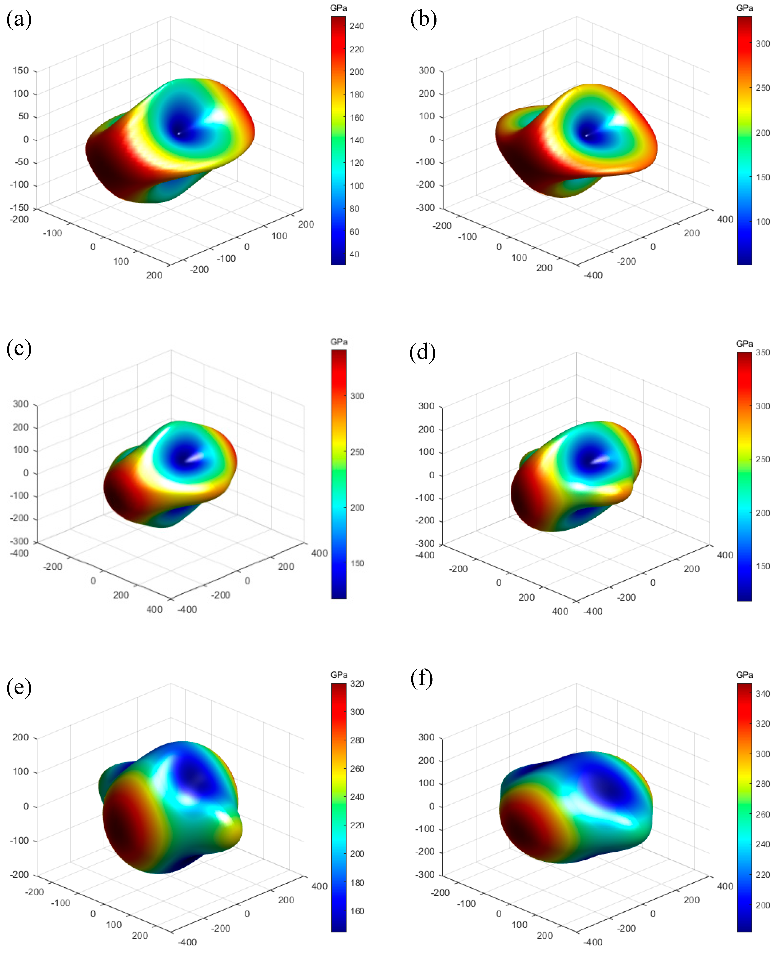
The three-dimensional curves of Young’s modulus are drawn according to the elastic modulus data, as shown in Figure 2 and Figure 3. The greater the difference between the 3D curves and the 3D sphere, the stronger the anisotropy of the material. Comparing K0.5Na0.5NbO3 in Figure 2a, it can be observed from Figure 2b–f that the 3D curves of Young’s modulus of the K0.5−xNa0.5LixNbO3 structure are significantly less deviated from the sphere, indicating that the incorporation of Li atoms makes K0.5−xNa0.5LixNbO3 less anisotropic.
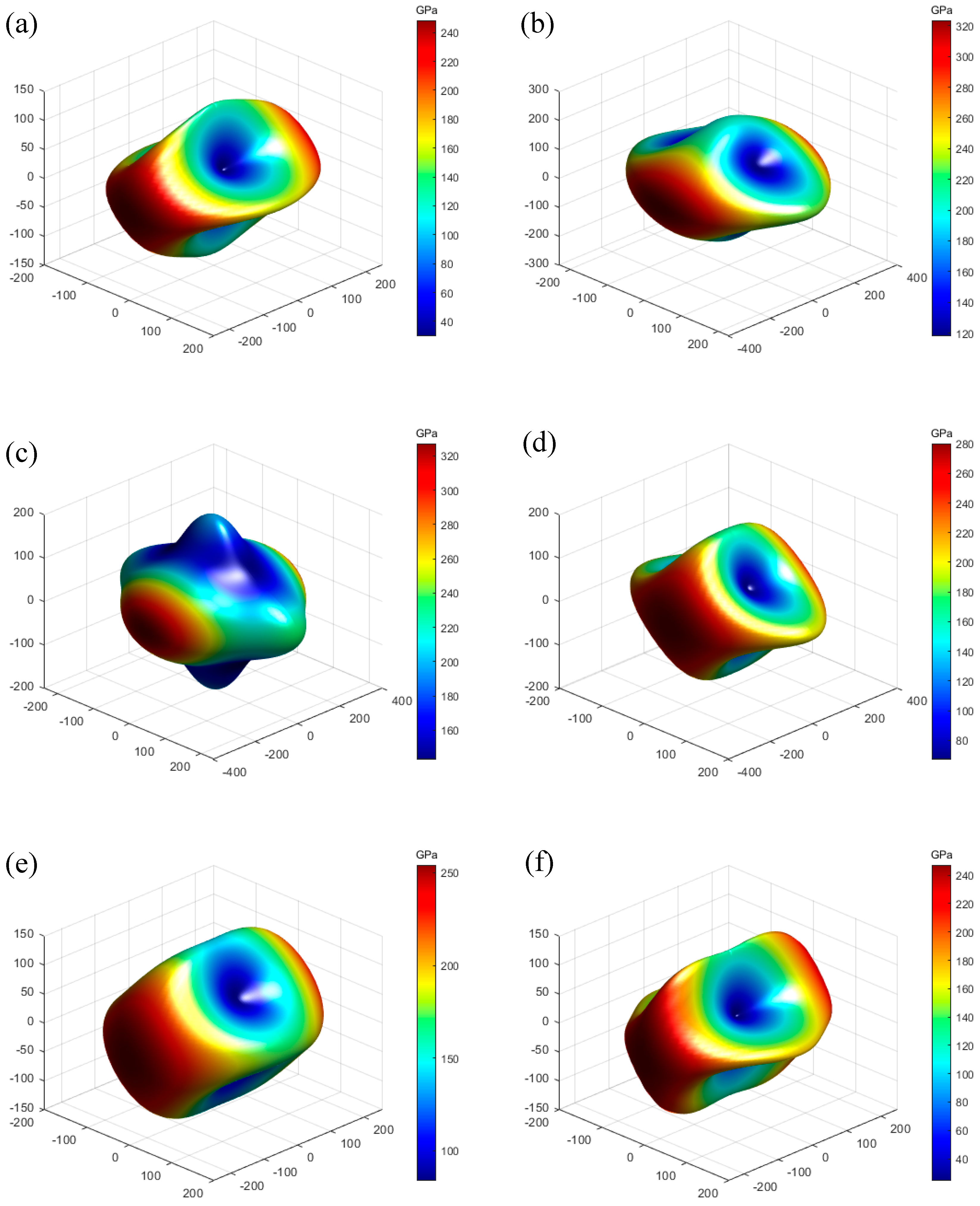
In the K0.5Na0.5−yLiyNbO3 system, comparing K0.5Na0.5NbO3 in Figure 3a, the anisotropy of Young’s modulus of Figure 3c (y = 0.125) and Figure 3f (y = 0.5) increase, while the anisotropy of doped structures in Figure 3b,d,e decrease.

3.4. Piezoelectric Properties

In the perovskite material system, there is a linear coupling relationship between mechanical properties and electrical properties. The piezoelectric constant describing the linear relationship between force and electricity calculation formula is as follows [39]:
d α j = i = 1 6 e α i S i j
where dαj refers to the piezoelectric charge tensor, α = 1–3 and j = 1–6; eαi is the piezoelectric stress tensor, i = 1–6; and Sij is the elastic compliance coefficient. Since dαj and eαi are 3 × 6 matrices and Sij is 6 × 6 matrices, we use α, i, and j to distinguish the rows and columns. In the piezoelectric charge tensor dαj, d33 is the most commonly used piezoelectric constant to characterize the performance of a piezoelectric material.
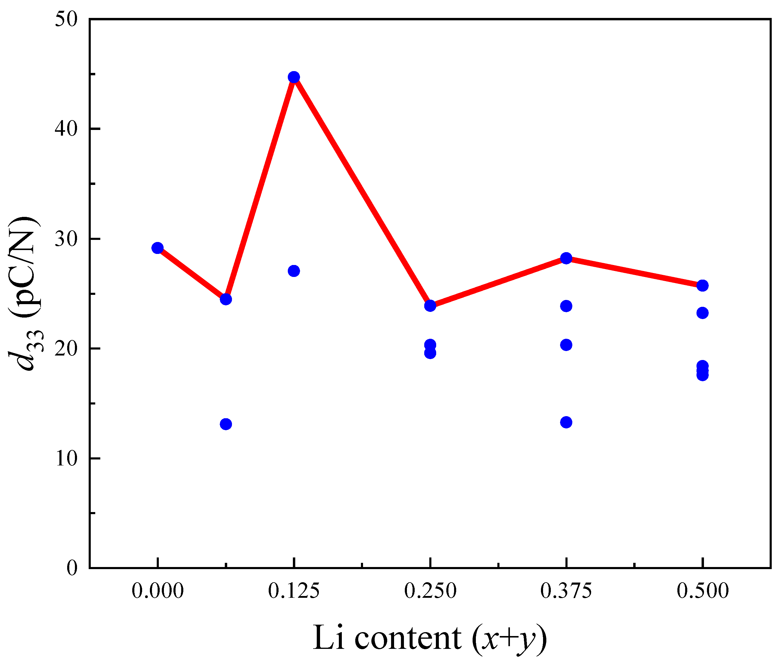
The e33 and d33 of KNbO3 and K0.5−xNa0.5−yLix+yNbO3 are also shown in Table 1. The d33 of KNbO3 and K0.5Na0.5NbO3 tetragonal phase are higher than that of KNbO3 and K0.5Na0.5NbO3 orthogonal phase. It can be inferred that the excellent piezoelectric properties in the polyphase coexisting region, explained from the aspect of crystal structure, may be due to the tetragonal phase with good piezoelectric properties compensating for the orthogonal phase with poor piezoelectric properties. In addition, the d33 of K0.5−xNa0.5−yLix+yNbO3 reached the maximum value (44.72 pC/N) when x = 0.125, and compared with the d33 of K0.5Na0.5NbO3 (29.15 pC/N), it is 1.5-fold higher. In order to more clearly reflect the variation trend of d33 with Li content, Figure 4 was plotted with all the d33 values (blue dots) of K0.5−xNa0.5−yLix+yNbO3 in Table 1. As shown in Figure 4, the maximum d33 (solid red line) for each Li content first increased and then decreased with the increase in Li, which is consistent with the experimental results.

3.5. The Born Effective Charge

In piezoelectric materials with perovskite structure, a larger Born effective charge tends to generate a larger spontaneous field. For piezoelectric materials, the greater the spontaneous polarization, the better the piezoelectric characteristics. Usually, the Born effective charge ( Z * ) can be obtained by using the following equation [40]:
P α = e Ω Z i α β * δ u i β
where P α means the macroscopic polarization;   i , α , β represent the i-th atom, the direction of the polarization component, and atomic displacement, respectively;   δ u represents the atomic displacement.
To investigate the effect of Li doped on piezoelectric properties, the Born effective charges of KNbO3, K0.5Na0.5NbO3 and K0.5Na0.375Li0.125NbO3 are calculated by the DFPT method, and the results are shown in Table 4. As can be seen from Table 4, due to the addition of Li, the Z * ¯ of Nb and OI atoms in K0.5Na0.375Li0.125NbO3 structure increase compared with those in KNbO3 and K0.5Na0.5NbO3. This is also consistent with the calculated results of piezoelectric properties.

3.6. Band Structure

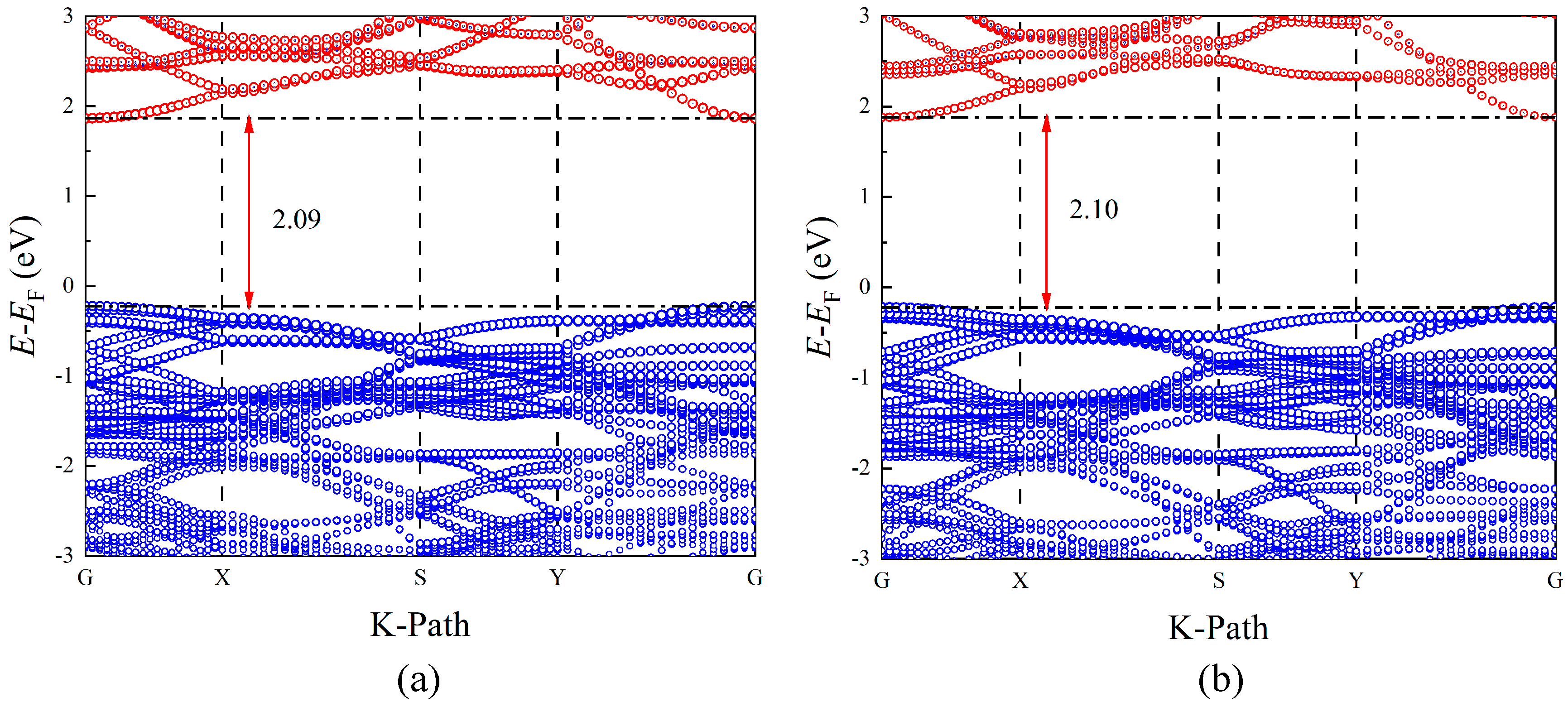
The band structures are shown in Figure 5. In order to calculate the band, the high-symmetry point path of G-X-S-Y-G is used. As can be seen from Figure 5, K0.5Na0.5NbO3 and K0.5Na0.375Li0.125NbO3 are all the direct band gap semiconductors, and the valence band maximum (VBM) and the conduction band minimum (CBM) are all located at the highly symmetric G-point. A direct band gap semiconductor has better energy utilization and electrical performance because its electrons will directly transition to a conduction band from a valence band when excited. In addition, the calculations show that the direct band gap of 2.09 eV for K0.5Na0.5NbO3 (comparable to the calculated result of 2.21 eV [31] and experiment value of 3.11 eV [41]) and 2.10 eV for K0.5Na0.375Li0.125NbO3 (1.96 eV [31]) is not much different. Li makes the CBM (1.87 to 1.88 eV) of K0.5Na0.375Li0.125NbO3 slightly move towards the higher energy level, and VBM (−0.22 eV) of K0.5Na0.375Li0.125NbO3 is consistent with K0.5Na0.5NbO3.

3.7. Density of States

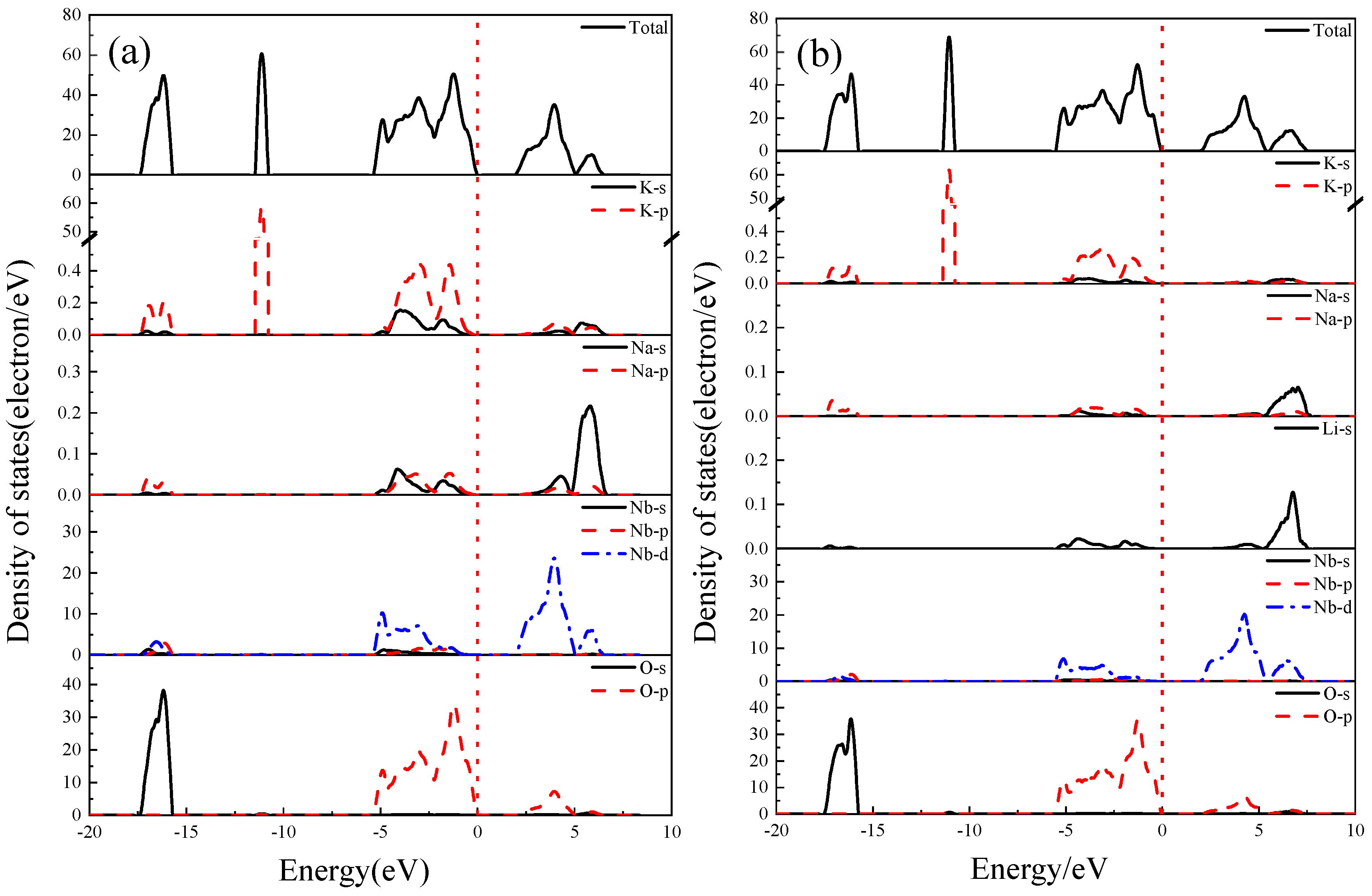
The total and partial density of states (DOS and PDOS) of K0.5Na0.5NbO3 and K0.5Na0.375Li0.125NbO3 are calculated, and the calculation results are shown in Figure 6. The DOS main peaks of K0.5Na0.375Li0.125NbO3 are mainly concentrated in four regions (−17~−15 eV, −12~−10 eV, −5~0 eV, 2~7 eV), which are similar to those of K0.5Na0.5NbO3.
For the K0.5Na0.375Li0.125NbO3 structure in Figure 6b, the valence band (−5~0 eV) near the Fermi surface is mainly composed of s and p orbitals of K, Na and Li, O-2p, and Nb-4d orbitals. Similar to K0.5Na0.5NbO3, the component of the conduction band is also contributed by O-2p and Nb-4d orbitals. However, compared with K0.5Na0.5NbO3, Li reduces the contribution of K and Na to the valence band and conduction band, making the peak shape sharp and the conduction band move towards a higher energy level. This indicates that the Li has a strong effect on the electronic structure of K0.5Na0.5NbO3.

4. Conclusions

In this paper, the structural, elastic, piezoelectric, and electronic properties of Li-doped K0.5−xNa0.5−yLix+yNbO3 were calculated using VASP software. The influence of different proportions of KNN-L was explored. The results show that the properties of KNN-L are related to the Li-doping content and the replaced K or Na atoms. The stability of the Na-replaced K0.5Na0.5−yLiyNbO3 structure is better than that of the K-replaced K0.5−xNa0.5LixNbO3, and it may be more inclined to form the K0.5Na0.5−yLiyNbO3 structure in experiments. The bulk modulus, the shear modulus and Young’s modulus of KNN-L are mostly higher than those of KNN, and the hardness value increases. The Poisson ratio of KNN-L is lower than that of most KNN, and the ductility is reduced. The incorporation of Li atoms makes K0.5-xNa0.5LixNbO3 less anisotropic, but the anisotropy of K0.5Na0.5−yLiyNbO3 decreases first and then increases with the addition of Li atoms. All doped systems are direct band gap semiconductors. The band gaps of K0.5Na0.5NbO3 (2.09 eV) and K0.5Na0.375Li0.125NbO3 (2.10 eV) are similar. Among the Li-doped KNN-L structures, K0.5Na0.375Li0.125NbO3 has the largest piezoelectric charge constant, d33 = 44.72 pC/N, which is 1.5 fold that of K0.5Na0.5NbO3 (29.15 pC/N). The results show that the Li-doped K0.5Na0.5NbO3 system helps to improve its piezoelectric capacity.

Author Contributions

H.L., methodology, software, investigation, conceptualization, writing—review and editing, visualization, supervision and funding acquisition; T.Z., validation, formal analysis, investigation, data curation, and writing—original draft preparation; K.X., investigation and writing—original draft preparation; H.W., investigation and writing—review and editing; W.L., investigation and writing—review and editing; J.L., investigation and writing—review and editing. All authors have read and agreed to the published version of the manuscript.

Funding

This research was funded by the Fundamental Research Funds for the Central Universities, CHD (Nos. 300102312406, 300102312405).

Institutional Review Board Statement

Not applicable.

Informed Consent Statement

Not applicable.

Data Availability Statement

Data are contained within this article.

Acknowledgments

The authors also acknowledge the Northwestern Polytechnical University High Performance Computing Center for the allocation of computing time on their machines.

Conflicts of Interest

The authors declare no conflicts of interest.

References

  1. Zheng, T.; Wu, J.; Xiao, D.; Zhu, J. Recent development in lead-free perovskite piezoelectric bulk materials. Prog. Mater. Sci. 2018, 98, 552–624. [Google Scholar] [CrossRef]
  2. Yang, Z.; Du, H.; Jin, L.; Poelman, D. High-performance lead-free bulk ceramics for electrical energy storage applications: Design strategies and challenges. J. Mater. Chem. A 2021, 9, 18026–18085. [Google Scholar] [CrossRef]
  3. Yang, L.; Kong, X.; Li, F.; Hao, H.; Cheng, Z.; Liu, H.; Li, J.F.; Zhang, S. Perovskite lead-free dielectrics for energy storage applications. Prog. Mater. Sci. 2019, 102, 72–108. [Google Scholar] [CrossRef]
  4. Xu, K.; Li, J.; Lv, X.; Wu, J.; Zhang, X.; Xiao, D.; Zhu, J. Superior piezoelectric properties in potassium–sodium niobate lead-free ceramics. Adv. Mater. 2016, 28, 8519–8523. [Google Scholar] [CrossRef]
  5. Jie, X.; Zhi, T.; Ting, Z.; Jia-Gang, W.; Ding-Quan, X.; Jian-Guo, Z. Research progress of high piezoelectric activity of potassium sodium niobate based lead-free ceramics. Acta Phys. Sin. 2020, 69, 19. [Google Scholar]
  6. Wu, B.; Wu, H.; Wu, J.; Xiao, D.; Zhu, J.; Pennycook, S.J. Giant piezoelectricity and high Curie temperature in nanostructured alkali niobate lead-free piezoceramics through phase coexistence. J. Am. Chem. Soc. 2016, 138, 15459–15464. [Google Scholar] [CrossRef]
  7. Panda, P.K.; Sahoo, B.; Thejas, T.S.; Krishna, M. High d33 lead-free piezoceramics: A Review. J. Electron. Mater. 2022, 51, 938–952. [Google Scholar] [CrossRef]
  8. Panda, P.K.; Sahoo, B. PZT to Lead Free Piezo Ceramics: A Review. Ferroelectrics 2015, 474, 128–143. [Google Scholar] [CrossRef]
  9. Lv, X.; Zhu, J.; Xiao, D.; Zhang, X.X.; Wu, J. Emerging new phase boundary in potassium sodium-niobate based ceramics. Chem. Soc. Rev. 2020, 49, 671–707. [Google Scholar] [CrossRef] [PubMed]
  10. Zhao, Y.; Ge, Y.; Zhang, X.; Zhao, Y.; Zhou, H.; Li, J.; Jin, H. Comprehensive investigation of Er2O3 doped (Li,K,Na)NbO3 ceramics rendering potential application in novel multifunctional devices. J. Alloy. Compd. 2016, 683, 171–177. [Google Scholar] [CrossRef]
  11. Guo, Y.; Kakimoto, K.I.; Ohsato, H. Phase transitional behavior and piezoelectric properties of (Na0.5K0.5)NbO3-LiNbO3 ceramics. Appl. Phys. Lett. 2004, 85, 4121–4123. [Google Scholar] [CrossRef]
  12. Song, H.C.; Cho, K.H.; Park, H.Y.; Ahn, C.W.; Nahm, S.; Uchino, K.; Park, S.H.; Lee, H.G. Microstructure and piezoelectric properties of (1−x)(Na0.5K0.5)NbO3xLiNbO3 Ceramics. J. Am. Ceram. Soc. 2007, 90, 1812–1816. [Google Scholar] [CrossRef]
  13. Du, H.; Tang, F.; Liu, D.; Zhu, D.; Zhou, W.; Qu, S. The microstructure and ferroelectric properties of (K0.5Na0.5)NbO3–LiNbO3 lead-free piezoelectric ceramics. Mater. Sci. Eng. B 2007, 136, 165–169. [Google Scholar] [CrossRef]
  14. Shen, Z.Y.; Li, Y.M.; Jiang, L.; Li, R.R.; Wang, Z.M.; Hong, Y.; Liao, R.H. Phase transition and electrical properties of LiNbO3-modified K0.49Na0.51NbO3 lead-free piezoceramics. J. Mater. Sci.-Mater. Electron. 2011, 22, 1071–1075. [Google Scholar] [CrossRef]
  15. Hao, J.; Li, W.; Zhai, J.; Chen, H. Progress in high-strain perovskite piezoelectric ceramics. Mater. Sci. Eng. R-Rep. 2019, 135, 1–57. [Google Scholar] [CrossRef]
  16. Machado, R.; Sepliarsky, M.; Stachiotti, M.G. Relative phase stability and lattice dynamics of NaNbO3 from first-principles calculations. Phys. Rev. B 2011, 84, 134107. [Google Scholar] [CrossRef]
  17. Xu, Y.Q.; Wu, S.Y.; Zhang, L.J.; Wu, L.N.; Ding, C.C. First-principles study of structural, electronic, elastic, and optical properties of cubic KNbO3 and KTaO3 crystals. Phys. Status Solidi B 2017, 254, 1600620. [Google Scholar] [CrossRef]
  18. Zhou, S.L.; Zhao, X.; Jiang, X.P.; Han, X.D. Electronic and optical properties of KNbO3, NaNbO3 and K0.5Na0.5NbO3 in paraelectric cubic phase: A comparative first-principles study. Chin. J. Struct. Chem. 2012, 31, 1095–1104. [Google Scholar]
  19. Li, H.; Wang, L.; Xu, L.; Li, A.; Mao, P.; Wu, Q.; Xie, Z. First-principles study on the structural, elastic, piezoelectric and electronic properties of (BaTiO3, LiTaO3)-modified KNbO3. Mater. Today Commun. 2021, 26, 102092. [Google Scholar] [CrossRef]
  20. Li, H.; Wu, Q.; Zhou, T.; Wang, Y.; Qiu, Y.; Xu, K.; Zhao, X.; He, Z.; Yu, P. Elastic, piezoelectric, and electronic properties of K1-xMxNbO3 (M = Li, Na): A first-principles study. AIP Adv. 2023, 13, 075012. [Google Scholar] [CrossRef]
  21. Kresse, G. Efficient iterative schemes for ab initio total-energy calculations using a plane-wave basis set. Phys. Rev. B 1996, 54, 11169. [Google Scholar] [CrossRef] [PubMed]
  22. Kresse, G.; Hafner, J. Ab initio molecular dynamics for open-shell transition metals. Phys. Rev. B 1993, 48, 13115–13118. [Google Scholar] [CrossRef] [PubMed]
  23. Blöchl, P. Projector augmented-wave method. Phys. Rev. B 1994, 50, 17953–17979. [Google Scholar] [CrossRef] [PubMed]
  24. Perdew, J.P.; Burke, K.; Ernzerhof, M. Generalized gradient approximation made simple. Phys. Rev. Lett. 1996, 77, 3865–3868. [Google Scholar] [CrossRef] [PubMed]
  25. Monkhorst, H.J.; Pack, J.D. Special points for Brillouin-zone integrations. Phys. Rev. B 1976, 13, 5188–5192. [Google Scholar] [CrossRef]
  26. Gonze, X.; Lee, C. Dynamical matrices, Born effective charges, dielectric permittivity tensors, and interatomic force constants from density-functional perturbation theory. Phys. Rev. B 1997, 55, 10355–10368. [Google Scholar] [CrossRef]
  27. Peng, Y.; Tan, Z.; An, J.; Zhu, J.; Zhang, Q. The tunable ferroelectricity and piezoelectricity of the KNN piezoceramics by Na concentrations: First-principles calculations. J. Eur. Ceram. Soc. 2019, 39, 5252–5259. [Google Scholar] [CrossRef]
  28. Katz, L.; Megaw, H.J.A.C. The structure of potassium niobate at room temperature: The solution of a pseudosymmetric structure by Fourier methods. Acta Crystallogr. 1967, 22, 639–648. [Google Scholar] [CrossRef]
  29. Hewat, A.W. Cubic-tetragonal-orthorhombic-rhombohedral ferroelectric transitions in perovskite potassium niobate: Neutron powder profile refinement of the structures. J. Phys. C Solid State Phys. 1973, 6, 2559. [Google Scholar] [CrossRef]
  30. Wang, Q.; Han, Y.; Liu, C.; Ma, Y.; Ren, W.; Gao, C. High-pressure electrical transport properties of KNbO3, Experimental and theoretical approaches. Appl. Phys. Lett. 2012, 100, 172905. [Google Scholar] [CrossRef]
  31. Hill, R. The elastic behaviour of a crystalline aggregate. Proc. Phys. Soc. 1952, 65, 349–354. [Google Scholar] [CrossRef]
  32. Kosec, M.; Bobnar, V.; Hrovat, M.; Bernard, J.; Malic, B.; Holc, J. New lead-free relaxors based on the K0.5Na0.5NbO3–SrTiO3 solid solution. J. Mater. Res. 2004, 19, 1849–1854. [Google Scholar] [CrossRef]
  33. Tellier, J.; Malic, B.; Dkhil, B.; Jenko, D.; Cilensek, J.; Kosec, M. Crystal structure and phase transitions of sodium potassium niobate perovskites. Solid State Sci. 2009, 11, 320–324. [Google Scholar] [CrossRef]
  34. Yang, D.; Wei, L.L.; Chao, X.L.; Yang, Z.P.; Zhou, X.Y. First-principles calculation of the effects of Li-doping on the structure and piezoelectricity of (K0.5Na0.5)NbO3 lead-free ceramics. Phys. Chem. Chem. Phys. 2016, 18, 7702–7706. [Google Scholar] [CrossRef]
  35. Egerton, L.; Dillon, D.M. Piezoelectric and dielectric properties of ceramics in the system potassium-sodium niobate. J. Am. Ceram. Soc. 1959, 42, 438–442. [Google Scholar] [CrossRef]
  36. Long, C.; Li, T.; Fan, H.; Wu, Y.; Zhou, L.; Li, Y.; Xiao, L.; Li, Y. Li-substituted K0.5Na0.5NbO3-based piezoelectric ceramics: Crystal structures and the effect of atmosphere on electrical properties. J. Alloys Compd. 2016, 658, 839–847. [Google Scholar] [CrossRef]
  37. Choi, M.; Oba, F.; Tanaka, I. First-principles study of native defects and lanthanum impurities in NaTaO3. Phys. Rev. B 2008, 78, 014115. [Google Scholar] [CrossRef]
  38. Li, C.; Xu, X.; Gao, Q.; Lu, Z. First-principle calculations of the effects of CaZrO3-doped on the structure of KNN lead-free ceramics. Ceram. Int. 2019, 45, 11092–11098. [Google Scholar] [CrossRef]
  39. Mouhat, F.; Coudert, F.-X. Necessary and sufficient elastic stability conditions in various crystal systems. Phys. Rev. B 2014, 90, 224104. [Google Scholar] [CrossRef]
  40. Li, F.; Zhang, S.; Xu, Z.; Wei, X.; Luo, J.; Shrout, T.R. Investigation of electromechanical properties and related temperature characteristics in domain-engineered tetragonal Pb(In1/2Nb1/2)O3-Pb(Mg1/3Nb2/3)O3-PbTiO3 crystals. J. Am. Ceram. Soc. 2010, 93, 2731–2734. [Google Scholar] [CrossRef]
  41. Zgonik, M.; Bernasconi, P.; Duelli, M.; Schlesser, R.; Günter, P.; Garrett, M.H.; Rytz, D.; Zhu, Y.; Wu, X. Dielectric, elastic, piezoelectric, electro-optic, and elasto-optic tensors of BaTiO3 crystals. Phys. Rev. B 1994, 50, 5941. [Google Scholar] [CrossRef] [PubMed]
Figure 1. Schematic diagram of KNbO3 and K0.5Na0.5NbO3 crystal structure: (a) KNbO3 orthogonal phase unit structure, (b) KNbO3 tetragonal phase unit structure, (c) K0.5Na0.5NbO3 orthogonal phase structure, and (d) K0.5Na0.5NbO3 tetragonal phase structure.
Materials 17 02118 g001
Figure 2. Three-dimensional curves of Young’s modulus E (in GPa) for Li doping K in K0.5 −xNa0.5LixNbO3: (a) x = 0, (b) x = 0.0625, (c) x = 0.125, (d) x = 0.25, (e) x = 0.375, and (f) x = 0.5.
Materials 17 02118 g002
Figure 3. Three-dimensional curves of Young’s modulus E (in GPa) for Li doping Na in K0.5Na0.5−yLiyNbO3: (a) y = 0, (b) y = 0.0625, (c) y = 0.125, (d) y = 0.25, (e) y = 0.375, and (f) y = 0.5.
Materials 17 02118 g003
Figure 4. The piezoelectric charge tensor d33 of KNN-L with different Li content.
Materials 17 02118 g004
Figure 5. Band structures of undoped and Li-doped KNN: (a) K0.5Na0.5NbO3 and (b) K0.5Na0.375Li0.125NbO3. (The red line is Nb contributing band, and the blue line is O contributing band).
Materials 17 02118 g005
Figure 6. DOS and PDOS of undoped and Li-doped KNN: (a) K0.5Na0.5NbO3 and (b) K0.5Na0.375Li0.125NbO3.
Materials 17 02118 g006
Table 1. Lattice parameters, formation energy, piezoelectric properties (e33 and d33) of KNbO3, K0.5Na0.5NbO3 and Li-doped K0.5−xNa0.5−yLix+yNbO3.
Structurea (Å)b (Å)c (Å)V3)Ef (eV)e33d33
KNbO3Orthogonal (Bmm2)Present5.8424.0175.886138.1/3.0023.74
Calc [19]5.8324.0205.869//3.0224.5
Calc [27]5.7893.9915.822134.5//23.25
Expt [28]5.6973.9715.721129.4///
Tetragonal (P4mm)Present4.0284.0284.25669.1/3.8066.17
Calc [27]4.0034.0034.19767.3//54.40
Expt [29]3.9963.9964.06364.9///
K0.5Na0.5NbO3Orthogonal (Bmm2)Present5.7643.9925.838134.3/3.9629.15
Expt. [30]5.65744////
Calc [27]//////29.12
Tetragonal (P4mm)Present4.0034.0034.19867.3/4.8169.44
Calc. [31]3.9783.9783.931//4.14149
Expt. [32]//////80
K0.5−xNa0.5−yLix+yNbO3x + y = 0.06Expt. [33]5.6223.9435.670125.702//187
x + y = 0.07Expt. [33]5.6213.9355.662125.270///
x + y = 0.0625x = 0.0625/y = 05.6593.9375.700127.0−12.633.5512.21
x = 0/y = 0.06255.6753.9465.707127.8−12.975.2924.49
x + y = 0.125x = 0.125/y = 05.6353.9165.691125.6−6.316.9827.04
x = 0/y = 0.1255.6843.9495.708128.1−6.637.9744.72
x + y = 0.25x = 0.25/y = 05.5963.8875.687123.7−6.425.1020.33
x = 0/y = 0.255.6903.9485.746129.1−6.853.7219.58
x = 0.125/y = 0.1255.6173.9125.734126.0−6.574.3123.89
x + y = 0.375x = 0.375/y = 05.5923.8395.651121.3−6.904.2220.33
x = 0/y = 0.3755.7013.9625.765130.2−7.284.2628,20
x = 0.125/y = 0.255.6133.8995.786126.6−6.873.6023.86
x = 0.25/y = 0.1255.6053.8985.696124.5−6.672.7113.26
x +y = 0.5x = 0.5/y = 05.5773.8985.723124.4−5.754.1917.97
x = 0/y = 0.55.6863.9415.832130.7−6.983.3825.72
x = 0.125/y = 0.3755.6533.9265.752127.7−6.643.6423.23
x = 0.375/y = 0.1255.5573.8985.647122.3−6.942.6318.39
x = 0.25/y = 0.255.6673.9335.723127.6−6.773.4817.56
Table 2. The calculated elastic constants Cij (in GPa) of K0.5−xNa0.5−yLix+yNbO3.
Li Content (x + y)x and yElastic Stiffness Coefficients
C11C12C13C22C23C33C44C55C66
0Present189.484.542.0313.080.6152.656.78.271.8
Calc [27]189.580.533.1327.772.9149.266.812.277.1
0.0625x = 0.0625/y = 0313.3104.694.7386.7105.0278.8100.513.6108.0
x = 0/y = 0.0625275.4111.385.1391.8105.6244.785.237.395.3
0.125x = 0.125/y = 0307.378.571.1376.276.5249.891.836.1103.4
x = 0/y = 0.125280.5110.682.7399.5110.7239.957.948.283.4
0.25x = 0.25/y = 0318.768.977.1382.679.2246.9105.435.891.3
x = 0/y = 0.25240.991.979.9347.1107.2211.580.019.487.3
x = 0.125/y = 0.125259.155.252.9335.372.8191.990.329.578.8
0.375x = 0.375/y = 0285.265.864.4343.754.2200.992.249.582.0
x = 0/y = 0.375201.585.753.1316.385.9170.773.326.977.2
x = 0.125/y = 0.25239.855.048.3314.779.2170.184.520.570.1
x = 0.25/y = 0.125233.579.237.3282.465.6164.487.012.274.5
0.5x = 0.5/y = 0329.9121.0126.0413.4116.9272.4100.161.695.5
x = 0/y = 0.5199.982.147.0310.283.1151.270.86.667.7
x = 0.125/y = 0.375208.534.551.1225.649.2168.374.212.571.6
x = 0.375/y = 0.125133.939.93.4144.716.3147.880.642.385.1
x = 0.25/y = 0.25232.1101.783.9317.984.6201.873.811.181.8
Table 3. The calculated elastic modulus (in GPa) of K0.5−xNa0.5−yLix+yNbO3.
Li Content (x + y)x and yBVBRBHGVGRGHEνG/B
0x = 0/y = 0118.8103.1110.957.227.342.2112.40.3310.38
0.0625x = 0.0625/y = 0176.4172.2174.389.444.066.7177.40.3300.38
x = 0/y = 0.0625168.4160.1164.284.271.177.7201.30.2960.47
0.125x = 0.125/y = 0153.9149.7151.893.476.084.7214.20.2650.56
x = 0/y = 0.125169.8159.8164.879.063.071.0186.20.3120.43
0.25x = 0.25/y = 0155.4151.5153.494.776.085.3216.00.2650.56
x = 0/y = 0.25150.8143.2147.072.050.161.1160.90.3180.42
x = 0.125/y = 0.125127.6121.1124.380.163.271.6180.30.2580.58
0.375x = 0.375/y = 0133.2127.1130.187.879.383.6206.50.2360.64
x = 0/y = 0.375126.4111.9119.266.453.860.1154.30.2840.50
x = 0.125/y = 0.25121.1113.3117.271.250.460.8155.50.2790.52
x = 0.25/y = 0.125116.1107.0111.567.937.852.9137.00.2950.47
0.5x = 0.5/y = 0193.7189.1191.494.989.192.0237.90.2930.48
x = 0/y = 0.5120.6106.2113.459.023.841.4110.60.3370.36
x = 0.125/y = 0.37596.988.492.762.834.048.4123.70.2780.52
x = 0.375/y = 0.12560.659.159.966.060.763.4140.50.1091.06
x = 0.25/y = 0.25143.6137.9140.865.535.250.3134.80.3400.36
Table 4. The Born effective charge of KNbO3, K0.5Na0.5NbO3 and K0.5Na0.375Li0.125NbO3.
MaterialsSpecies Z x x * Z y y * Z z z * Z * ¯
KNK1.2081.1351.1771.173
Nb7.4548.8366.2437.511
OI−1.354−6.915−1.437−3.236
OII−3.654−1.528−2.992−2.724
KNNK1.169 1.150 1.170 1.163
Na1.234 1.142 1.140 1.172
Nb7.664 8.740 6.473 7.625
OI−1.378 −7.068 −1.430 −3.292
OII−3.779 −1.469 −3.117 −2.788
KNN-LK1.179 1.076 1.152 1.136
Na1.342 1.324 1.320 1.329
Li1.067 1.056 0.993 1.039
Nb7.888 8.739 7.260 7.962
OI−1.513 −7.087 −1.504 −3.368
OII−3.444 −1.476 −3.234 −2.718
Disclaimer/Publisher’s Note: The statements, opinions and data contained in all publications are solely those of the individual author(s) and contributor(s) and not of MDPI and/or the editor(s). MDPI and/or the editor(s) disclaim responsibility for any injury to people or property resulting from any ideas, methods, instructions or products referred to in the content.