
Effect of Post-Weld Heat Treatment on Residual Stress and Fatigue Crack Propagation Behavior in Linear Friction Welded Ti-6Al-4V Alloy


 and
and
Abstract
1. Introduction
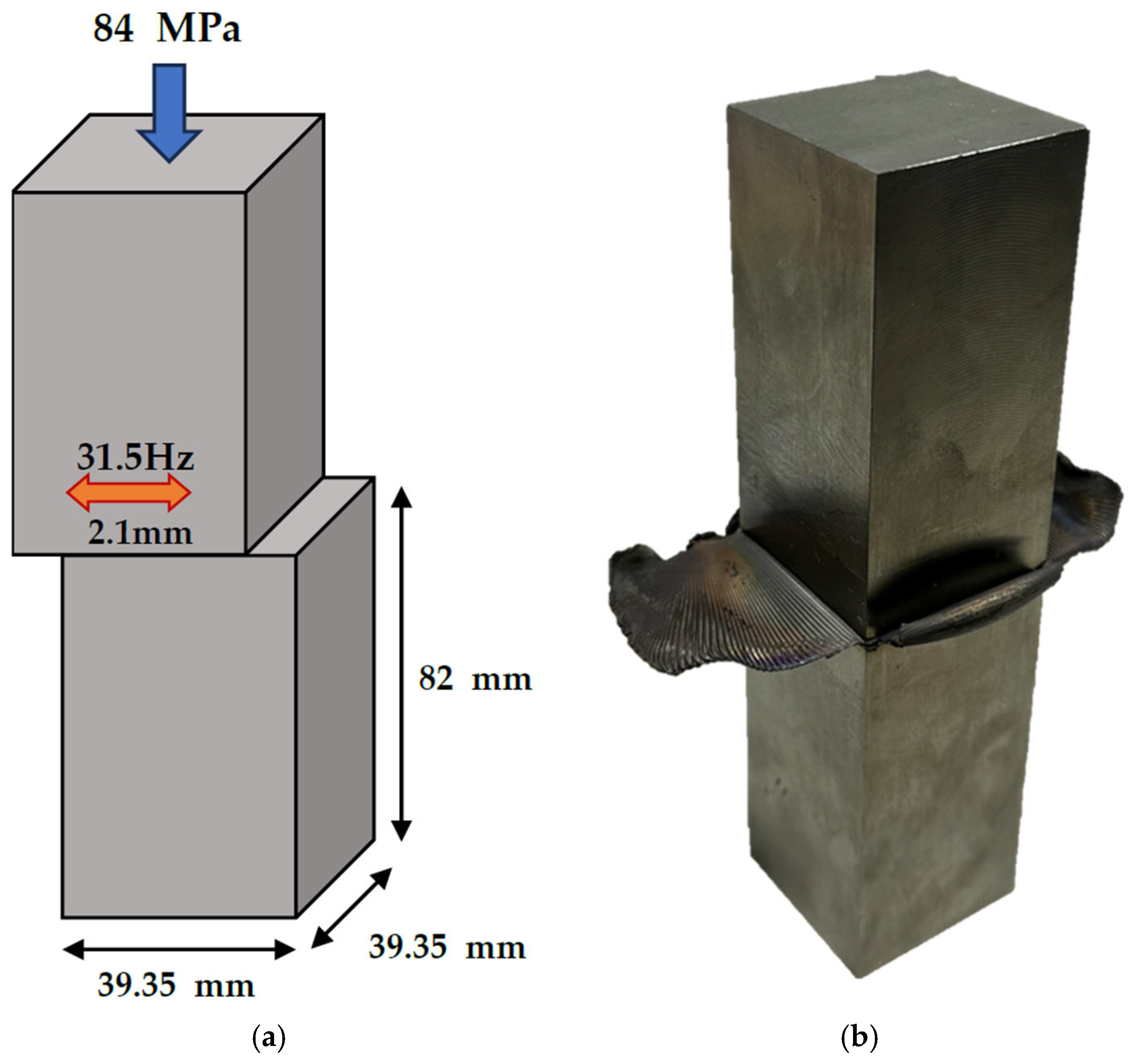
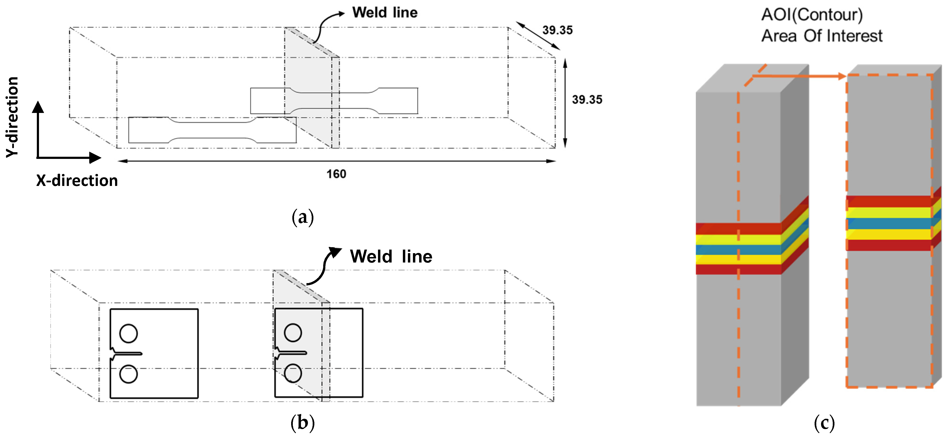
2. Materials and Methods

| Elements | C | Fe | Al | V | N | O | H | Ti |
|---|---|---|---|---|---|---|---|---|
| mass (%) | 0.009 | 0.18 | 6.25 | 4.26 | 0.003 | 0.09 | 0.0025 | Bal. |
3. Results and Discussion
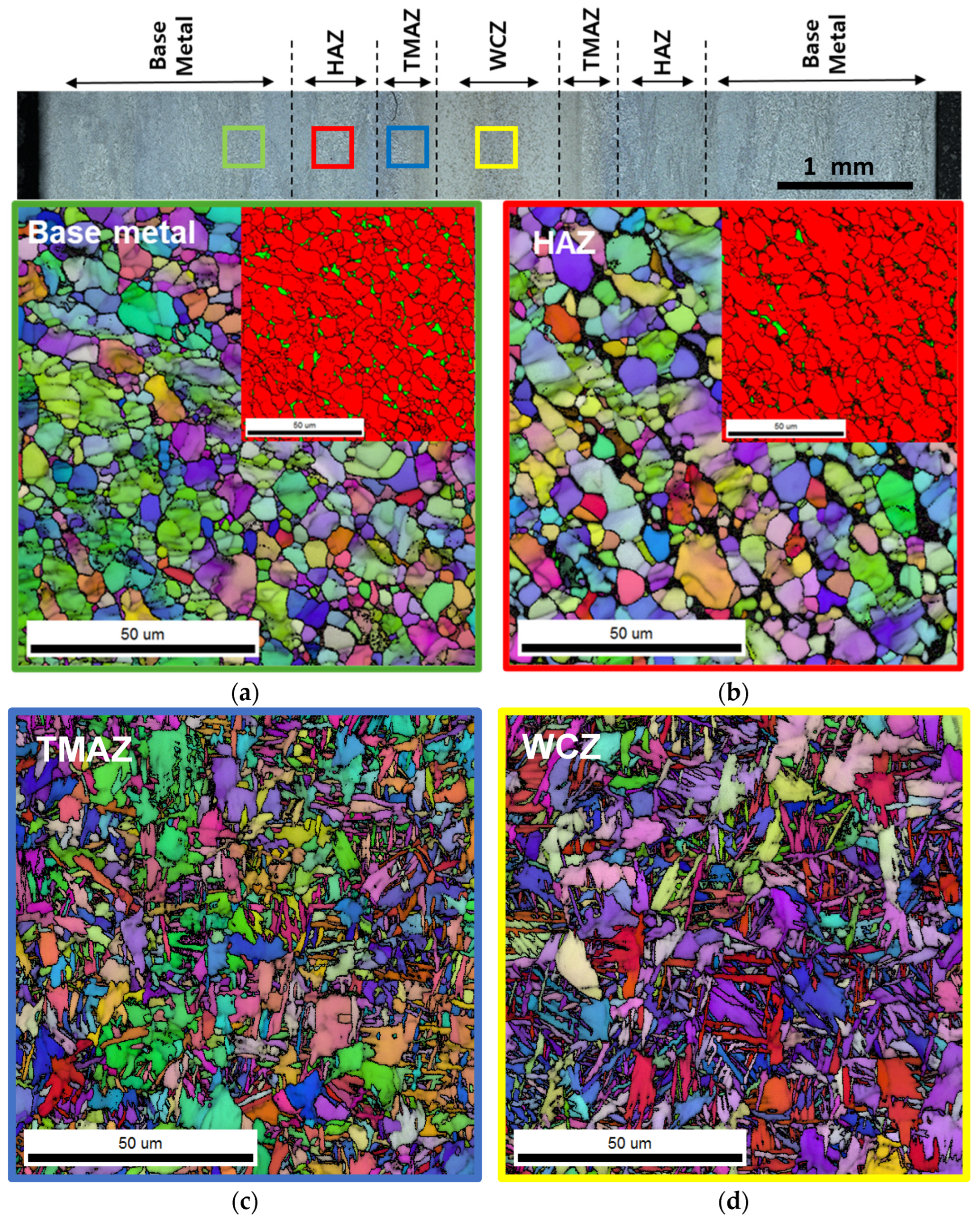
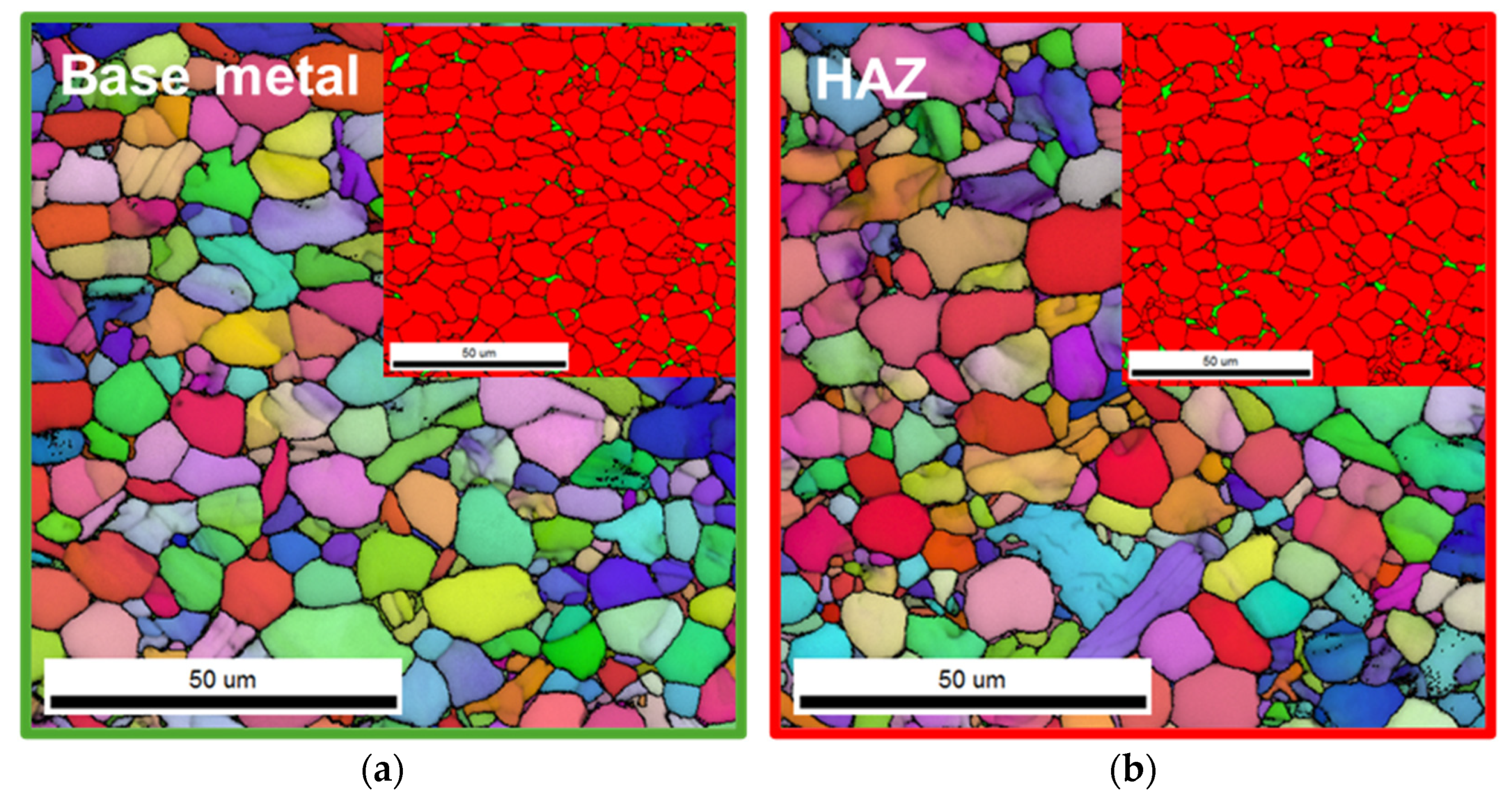
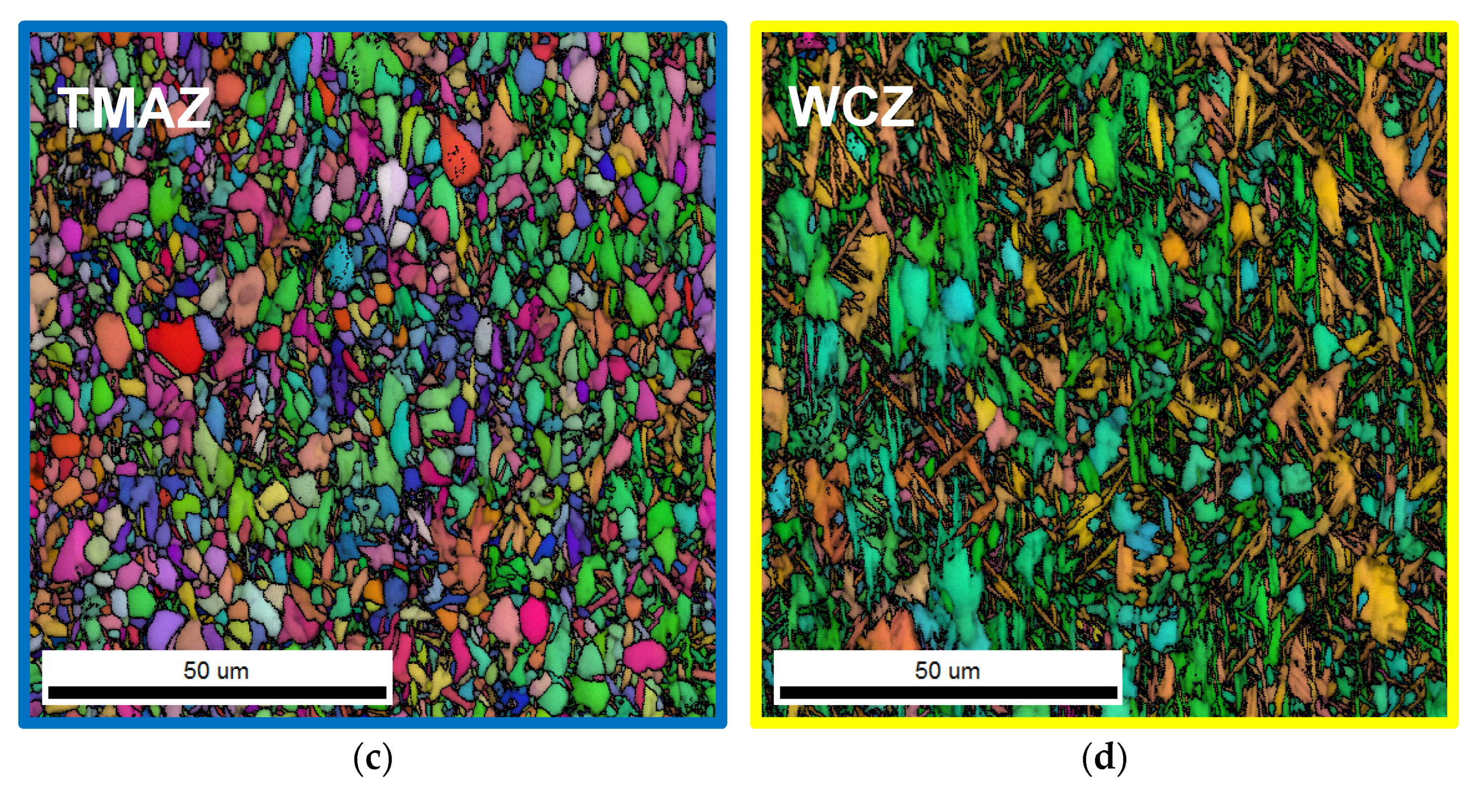
3.1. Microstructure and Properties After LFW
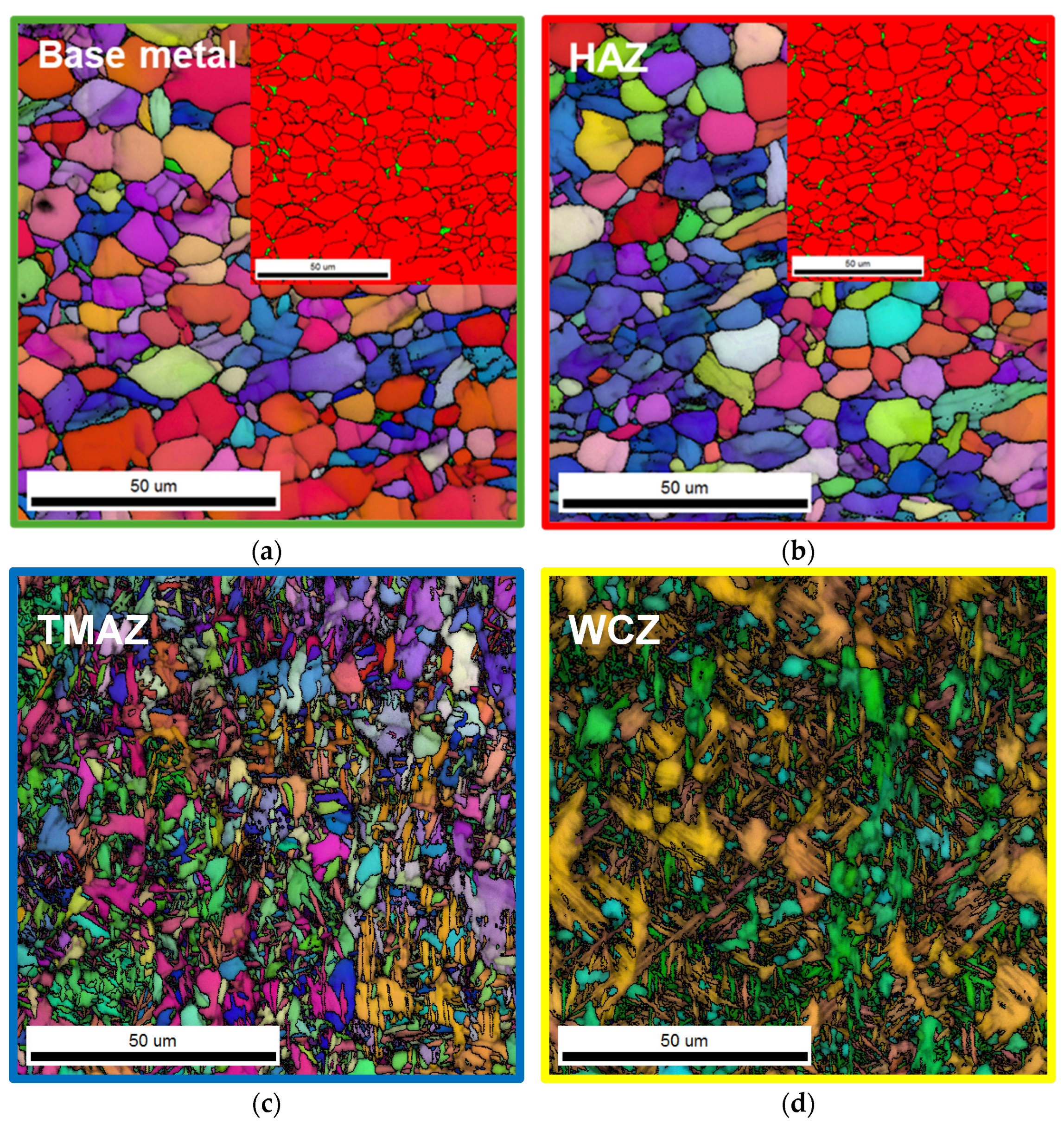
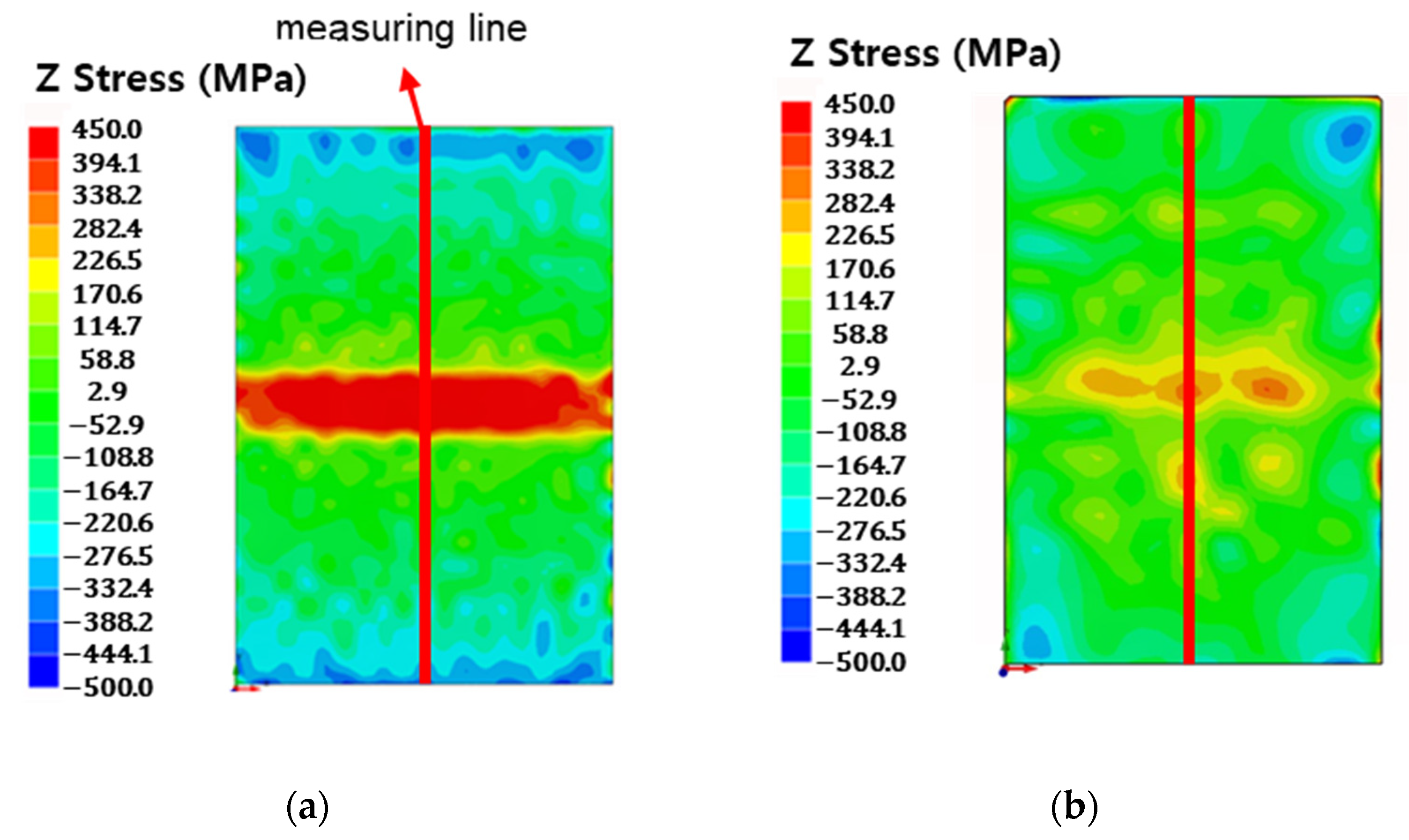
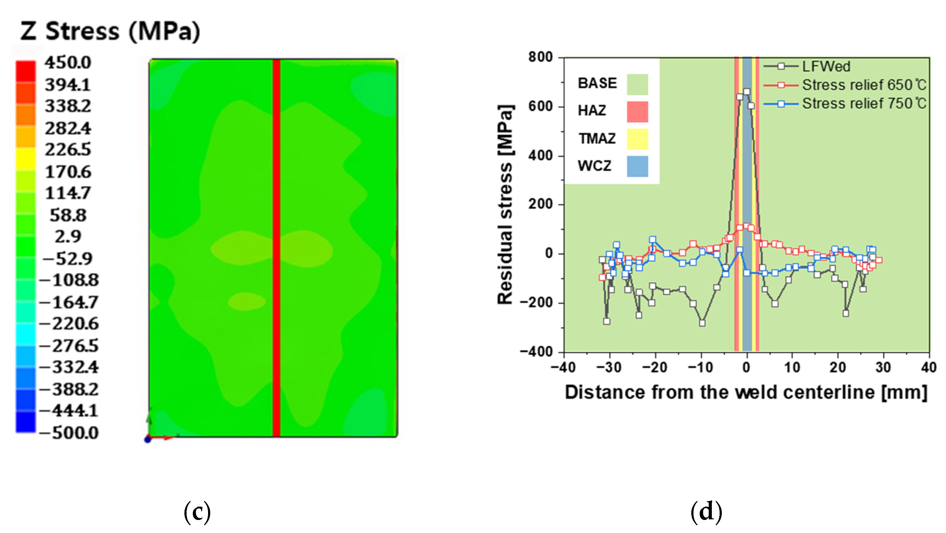
3.2. Effects of Post-Weld Heat Treatment
4. Conclusions
Author Contributions
Funding
Institutional Review Board Statement
Informed Consent Statement
Data Availability Statement
Conflicts of Interest
References
- Welsch, G.; Boyer, R.; Collings, E. Materials Properties Handbook: Titanium Alloys; ASM International: Novelty, OH, USA, 1993. [Google Scholar]
- Peters, M.; Kumpfert, J.; Ward, C.H.; Leyens, C. Titanium alloys for aerospace applications. Adv. Eng. Mater. 2003, 5, 419–427. [Google Scholar] [CrossRef]
- Leyens, C.; Peters, M. Titanium and Titanium Alloys: Fundamentals and Applications; John Wiley & Sons: Hoboken, NJ, USA, 2003. [Google Scholar]
- Ezugwu, E.; Wang, Z. Titanium alloys and their machinability—A review. J. Mater. Process. Technol. 1997, 68, 262–274. [Google Scholar] [CrossRef]
- Allen, P. Titanium alloy development. Adv. Mater. Process. 1996, 150, 35–38. [Google Scholar]
- Geetha, M.; Singh, A.K.; Asokamani, R.; Gogia, A.K. Ti based biomaterials, the ultimate choice for orthopaedic implants—A review. Prog. Mater. Sci. 2009, 54, 397–425. [Google Scholar] [CrossRef]
- Kaur, M.; Singh, K. Review on titanium and titanium based alloys as biomaterials for orthopaedic applications. Mater. Sci. Eng. C 2019, 102, 844–862. [Google Scholar] [CrossRef]
- Zhang, L.-C.; Chen, L.-Y. A review on biomedical titanium alloys; recent progress and prospect. Adv. Eng. Mater. 2019, 21, 1801215. [Google Scholar] [CrossRef]
- Veiga, C.; Davim, J.; Loureiro, A. Properties and applications of titanium alloys: A brief review. Rev. Adv. Mater. Sci 2012, 32, 133–148. [Google Scholar]
- Rack, H.; Qazi, J. Titanium alloys for biomedical applications. Mater. Sci. Eng. C 2006, 26, 1269–1277. [Google Scholar] [CrossRef]
- Gomez-Gallegos, A.; Mandal, P.; Gonzalez, D.; Zuelli, N.; Blackwell, P. Studies on titanium alloys for aerospace application. Defect Diffus. Forum 2018, 385, 419–423. [Google Scholar] [CrossRef]
- Boyer, R.R. Aerospace applications of beta titanium alloys. JOM 1994, 46, 20–23. [Google Scholar] [CrossRef]
- Balazic, M.; Kopac, J.; Jackson, M.J.; Ahmed, W. Titanium and titanium alloy applications in medicine. Int. J. Nano Biomater. 2007, 1, 3–34. [Google Scholar] [CrossRef]
- Sherman, A.; Allison, J. Potential for automotive applications of titanium alloys. SAE Trans. 1986, 95, 806–817. [Google Scholar]
- Sachdev, A.K.; Kulkarni, K.; Fang, Z.Z.; Yang, R.; Girshov, V. Titanium for automotive applications: Challenges and opportunities in materials and processing. JOM 2012, 64, 553–565. [Google Scholar] [CrossRef]
- Schauerte, O. Titanium in automotive production. Adv. Eng. Mater. 2003, 5, 411–418. [Google Scholar] [CrossRef]
- Bhamji, I.; Preuss, M.; Threadgill, P.L.; Addison, A.C. Solid state joining of metals by linear friction welding: A literature review. Mater. Sci. Technol. 2011, 27, 2–12. [Google Scholar] [CrossRef]
- Guo, Y.; Jung, T.; Lung, Y.; Li, H.; Bray, S.; Bowen, P. Microstructure and microhardness of Ti6246 linear friction weld. Mater. Sci. Eng. A 2013, 562, 17–24. [Google Scholar] [CrossRef]
- Karadge, M.; Preuss, M.; Lovell, C.; Withers, P.J.; Bray, S. Texture development in Ti–6Al–4V linear friction welds. Mater. Sci. Eng. A 2007, 459, 182–191. [Google Scholar] [CrossRef]
- Guo, Y.; Chiu, Y.; Attallah, M.; Li, H. Characterization of dissimilar linear friction welds of alpha + beta titanium alloys. J. Mater. Eng. Perform. 2012, 21, 770–776. [Google Scholar] [CrossRef]
- Li, W.; Vairis, A.; Preuss, M.; Ma, T. Linear and rotary friction welding review. Int. Mater. Rev. 2016, 61, 71–100. [Google Scholar] [CrossRef]
- McAndrew, A.R.; Colegrove, P.A.; Buhr, C.; Flipo, B.C.D.; Vairis, A. A literature review of Ti-6Al-4V linear friction welding. Prog. Mater. Sci. 2018, 92, 225–257. [Google Scholar] [CrossRef]
- McAndrew, A.R.; Colegrove, P.A.; Addison, A.C.; Flipo, B.C.D.; Russell, M.J. Modelling the influence of the process inputs on the removal of surface contaminants from Ti-6Al-4V linear friction welds. Mater. Des. 2015, 66, 183–195. [Google Scholar] [CrossRef]
- McAndrew, A.R.; Colegrove, P.A.; Addison, A.C.; Flipo, B.C.D.; Russell, M.J. Energy and force analysis of Ti-6Al-4V linear friction welds for computational modeling input and validation data. Metall. Mater. Trans. A 2014, 45, 6118–6128. [Google Scholar] [CrossRef]
- Romero, J.; Attallah, M.M.; Preuss, M.; Karadge, M.; Bray, S.E. Effect of the forging pressure on the microstructure and residual stress development in Ti–6Al–4V linear friction welds. Acta Mater. 2009, 57, 5582–5592. [Google Scholar] [CrossRef]
- Frankel, P.; Preuss, M.; Steuwer, A.; Withers, P.J.; Bray, S. Comparison of residual stresses in Ti–6Al–4V and Ti–6Al–2Sn–4Zr–2Mo linear friction welds. Mater. Sci. Technol. 2009, 25, 640–650. [Google Scholar] [CrossRef]
- Choi, J.-W.; Tsuruyama, H.; Hino, R.; Aoki, Y.; Morisada, Y.; Fujii, H.; Lee, S.-J. Dissimilar linear friction welding of AZ31 magnesium alloy and AA5052-H34 aluminum alloy. Materialia 2024, 36, 102160. [Google Scholar] [CrossRef]
- Guo, Z.; Ma, T.; Yang, X.; Li, W.; Xu, Q.; Li, Y.; Li, J.; Vairis, A. Comprehensive investigation on linear friction welding a dissimilar material joint between Ti17(α+β) and Ti17(β): Microstructure evolution, failure mechanisms, with simultaneous optimization of tensile and fatigue properties. Mater. Sci. Eng. A 2024, 909, 146818. [Google Scholar] [CrossRef]
- Khan, F.; Miura, T.; Ito, T.; Morisada, Y.; Ushioda, K.; Fujii, H. Sound dissimilar linear friction welding of A7075-T6 Al and mild steel by simultaneous interfacial deformation using higher forging speed. J. Manuf. Process. 2024, 109, 512–523. [Google Scholar] [CrossRef]
- Gangil, N.; Mishra, A.; Lone, N.F.; Bajaj, D.; Chen, D.; Haider, J.; Chen, X.; Konovalov, S.; Siddiquee, A.N. Linear Friction Welding of Similar and Dissimilar Materials: A Review. Met. Mater. Int. 2025, 31, 1–21. [Google Scholar] [CrossRef]
- Rajan, S.; Wanjara, P.; Gholipour, J.; Kabir, A.S. Joining of Dissimilar Alloys Ti-6Al-4V and Ti-6Al-2Sn-4Zr-2Mo-0.1Si Using Linear Friction Welding. Materials 2020, 13, 3664. [Google Scholar] [CrossRef]
- Rajan, S.; Wanjara, P.; Gholipour, J.; Kabir, A.S. Fatigue Behavior of Linear Friction Welded Ti-6Al-4V and Ti-6Al-2Sn-4Zr-2Mo-0.1Si Dissimilar Welds. Materials 2021, 14, 3136. [Google Scholar] [CrossRef]
- Rajan, S.; Wanjara, P.; Gholipour, J.; Kabir, A.S. Microstructure, Tensile Properties, and Fatigue Behavior of Linear Friction-Welded Ti-6Al-2Sn-4Zr-2Mo-0.1Si. Materials 2021, 14, 30. [Google Scholar] [CrossRef] [PubMed]
- Jeon, S.; Ha, H.; Lee, D.J.; Park, H.; Kwon, Y.N.; Choi, H.; Sung, H. High-integrity diffusion bonding of laser powder bed fused, forged, and rolled Ti–6Al–4V alloys. J. Meter. Res. Technol. 2025, 35, 2108–2118. [Google Scholar] [CrossRef]
- Jeong, D.; Kwon, Y.; Goto, M.; Kim, S. High cycle fatigue and fatigue crack propagation behaviors of β-annealed Ti-6Al-4V alloy. Int. J. Mech. Mater. Eng. 2017, 12, 1. [Google Scholar] [CrossRef]
- Bandyopadhyay, R.; Rotella, J.; Naragani, D.; Park, J.-S.; Eff, M.; Sangid, M.D. Residual Strain Analysis in Linear Friction Welds of Similar and Dissimilar Titanium Alloys Using Energy Dispersive X-Ray Diffraction. Metall. Mater. Trans. A 2019, 50, 704–718. [Google Scholar] [CrossRef]
- Chen, F.; Liu, X.; Zhang, H.; Luo, Y.; Lu, N.; Liu, Y.; Xiao, X. Assessment of fatigue crack propagation and lifetime of double-sided U-rib welds considering welding residual stress relaxation. Ocean Eng. 2025, 332, 121400. [Google Scholar] [CrossRef]


| Specimens | BM | HAZ | TMAZ * | WCZ * |
|---|---|---|---|---|
| LFWed | 3.4 ± 2.8 | 4.0 ± 3.2 | 2.3 ± 1.6 | 2.3 ± 1.8 |
| SR650 | 4.5 ± 3.6 | 4.4 ± 3.2 | 2.2 ± 1.5 | 2.1 ± 1.7 |
| SR750 | 4.7 ± 3.3 | 4.6 ± 3.5 | 2.4 ± 1.4 | 2.0 ± 1.5 |
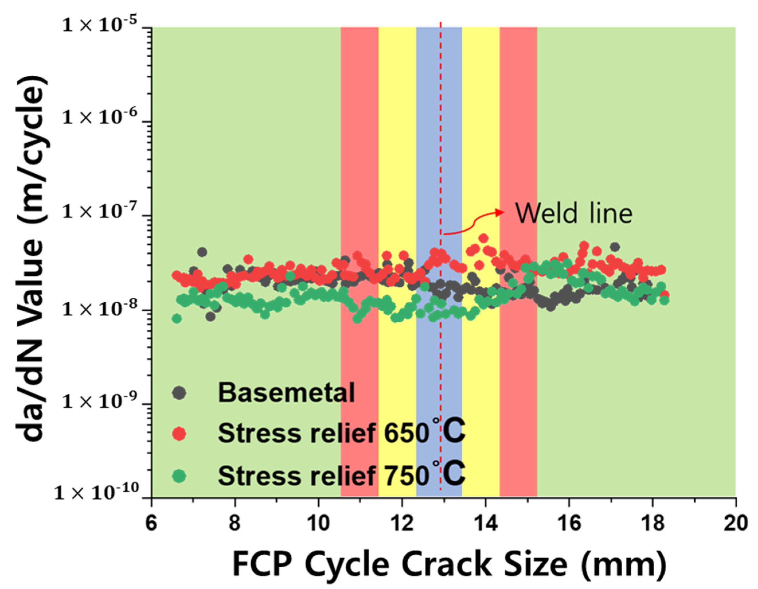
| Specimens | Average Crack Growth Rate (m/cycle, × 10−8) | Standard Deviation (m/cycle, × 10−8) |
|---|---|---|
| Base Metal | 1.96 | 0.55 |
| SR650 | 2.74 | 0.63 |
| SR750 | 1.48 | 0.51 |
Disclaimer/Publisher’s Note: The statements, opinions and data contained in all publications are solely those of the individual author(s) and contributor(s) and not of MDPI and/or the editor(s). MDPI and/or the editor(s) disclaim responsibility for any injury to people or property resulting from any ideas, methods, instructions or products referred to in the content. |
© 2025 by the authors. Licensee MDPI, Basel, Switzerland. This article is an open access article distributed under the terms and conditions of the Creative Commons Attribution (CC BY) license (https://creativecommons.org/licenses/by/4.0/).
Share and Cite
Lee, S.; Choi, H.; Cho, Y.; Baek, M.J.; Park, H.; Seok, M.-Y.; Kwon, Y.N.; Kang, N.; Lee, D.J. Effect of Post-Weld Heat Treatment on Residual Stress and Fatigue Crack Propagation Behavior in Linear Friction Welded Ti-6Al-4V Alloy. Materials 2025, 18, 3285. https://doi.org/10.3390/ma18143285
Lee S, Choi H, Cho Y, Baek MJ, Park H, Seok M-Y, Kwon YN, Kang N, Lee DJ. Effect of Post-Weld Heat Treatment on Residual Stress and Fatigue Crack Propagation Behavior in Linear Friction Welded Ti-6Al-4V Alloy. Materials. 2025; 18(14):3285. https://doi.org/10.3390/ma18143285
Chicago/Turabian StyleLee, Sungkyoung, Hyunsung Choi, Yunji Cho, Min Jae Baek, Hyeonil Park, Moo-Young Seok, Yong Nam Kwon, Namhyun Kang, and Dong Jun Lee. 2025. "Effect of Post-Weld Heat Treatment on Residual Stress and Fatigue Crack Propagation Behavior in Linear Friction Welded Ti-6Al-4V Alloy" Materials 18, no. 14: 3285. https://doi.org/10.3390/ma18143285
APA StyleLee, S., Choi, H., Cho, Y., Baek, M. J., Park, H., Seok, M.-Y., Kwon, Y. N., Kang, N., & Lee, D. J. (2025). Effect of Post-Weld Heat Treatment on Residual Stress and Fatigue Crack Propagation Behavior in Linear Friction Welded Ti-6Al-4V Alloy. Materials, 18(14), 3285. https://doi.org/10.3390/ma18143285