
Machining Safety in Dry Rough Milling of Casting Magnesium Alloy AZ91D Using Carbide End Mills with Different Geometries


Abstract
:1. Introduction
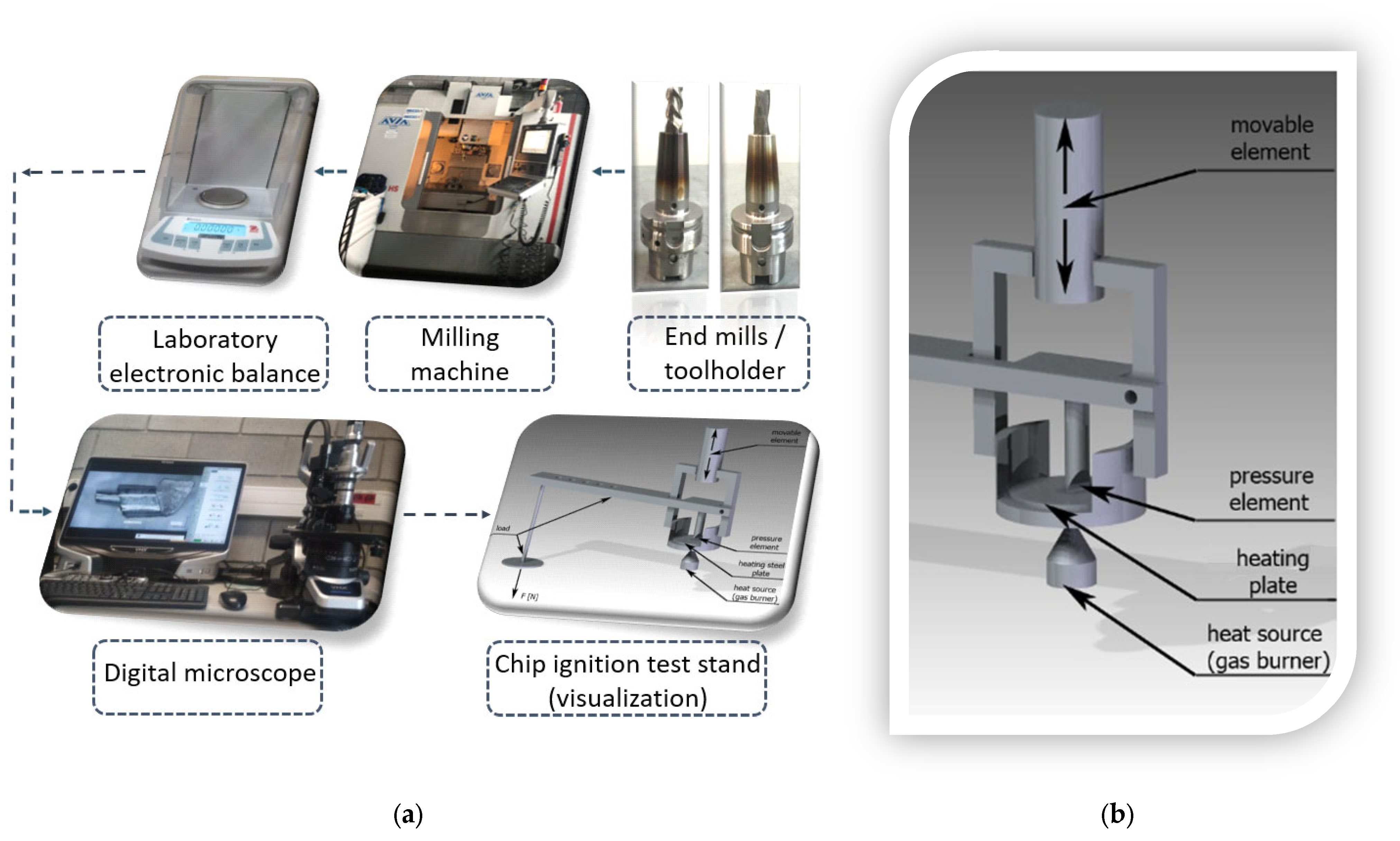
2. Materials, Methodology, Aims, and Scope of the Study
3. Results
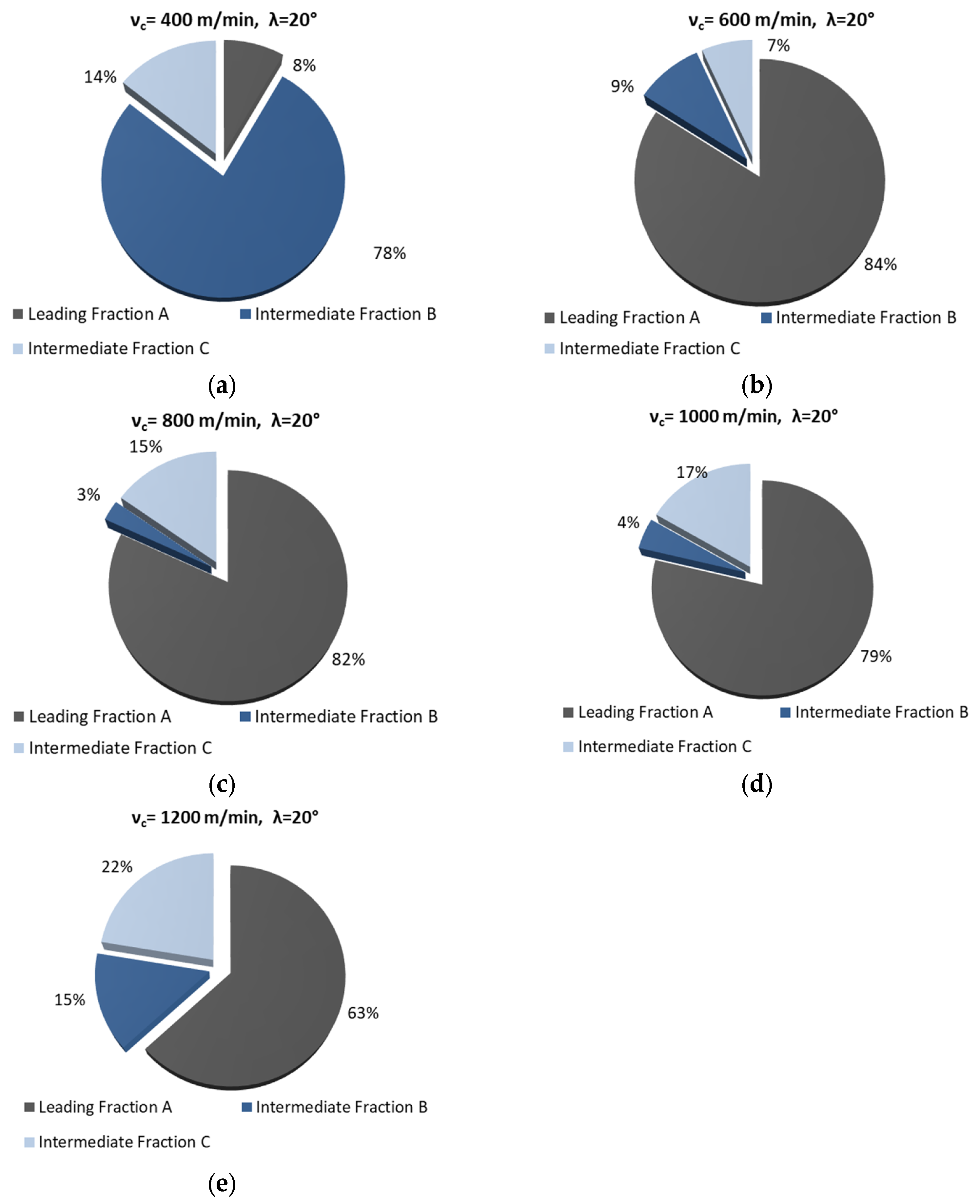
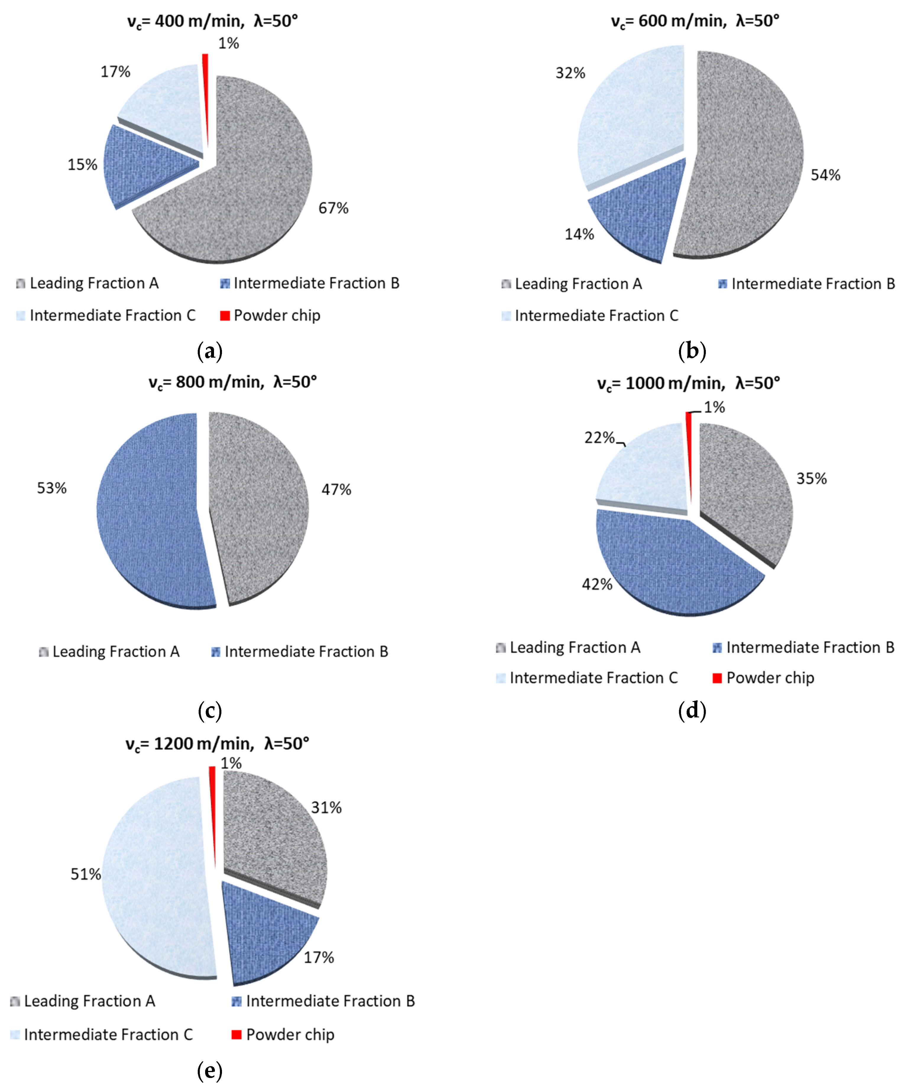
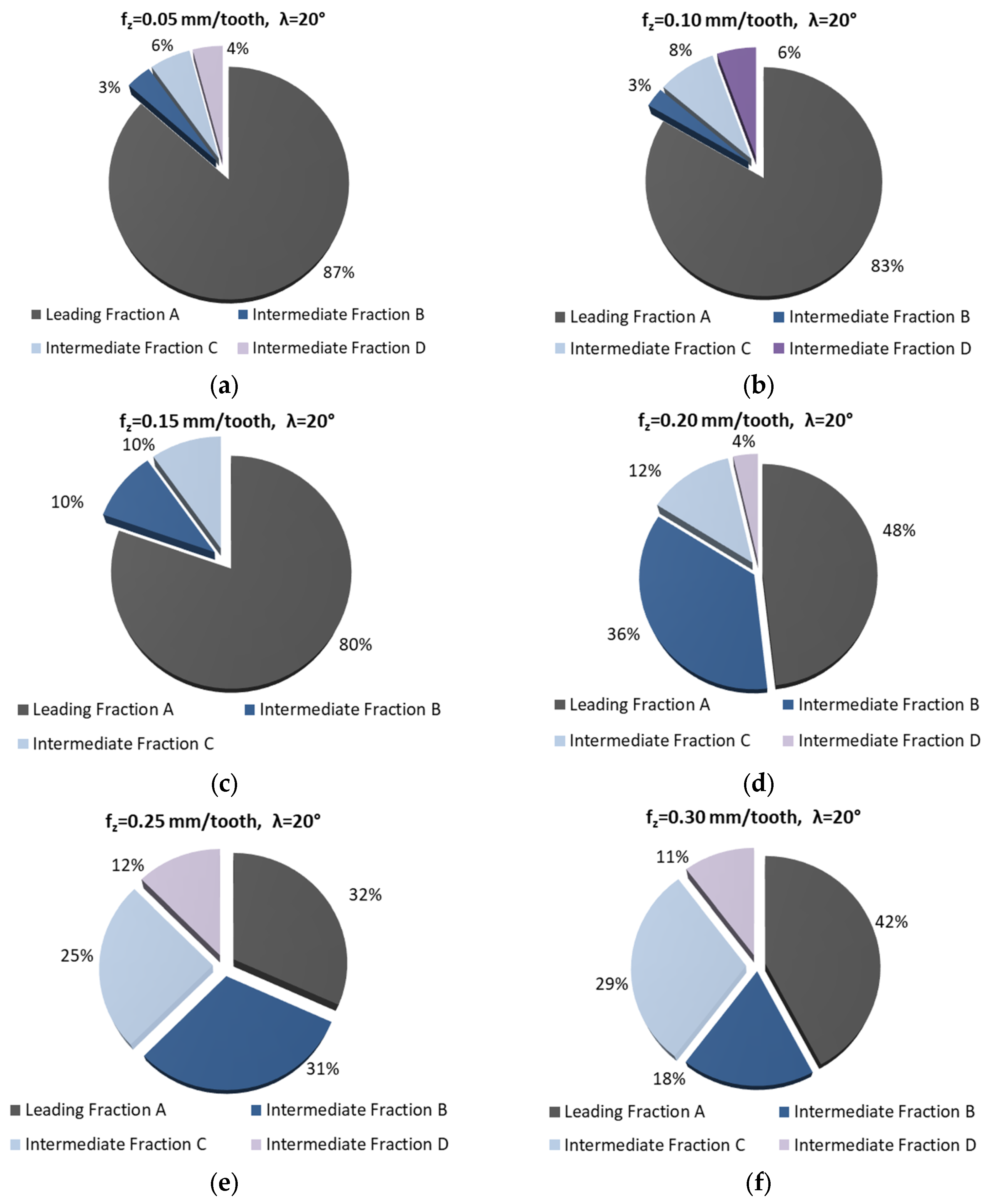
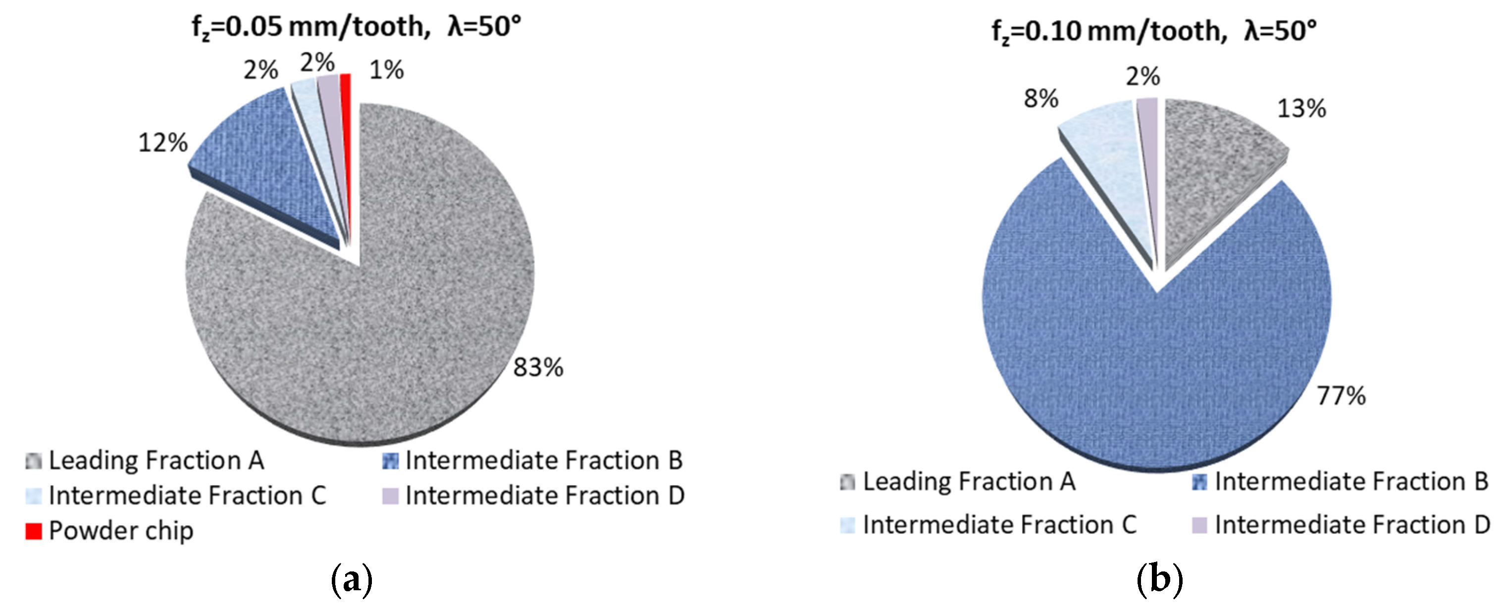
3.1. Fractions and Percentage Share of Chips
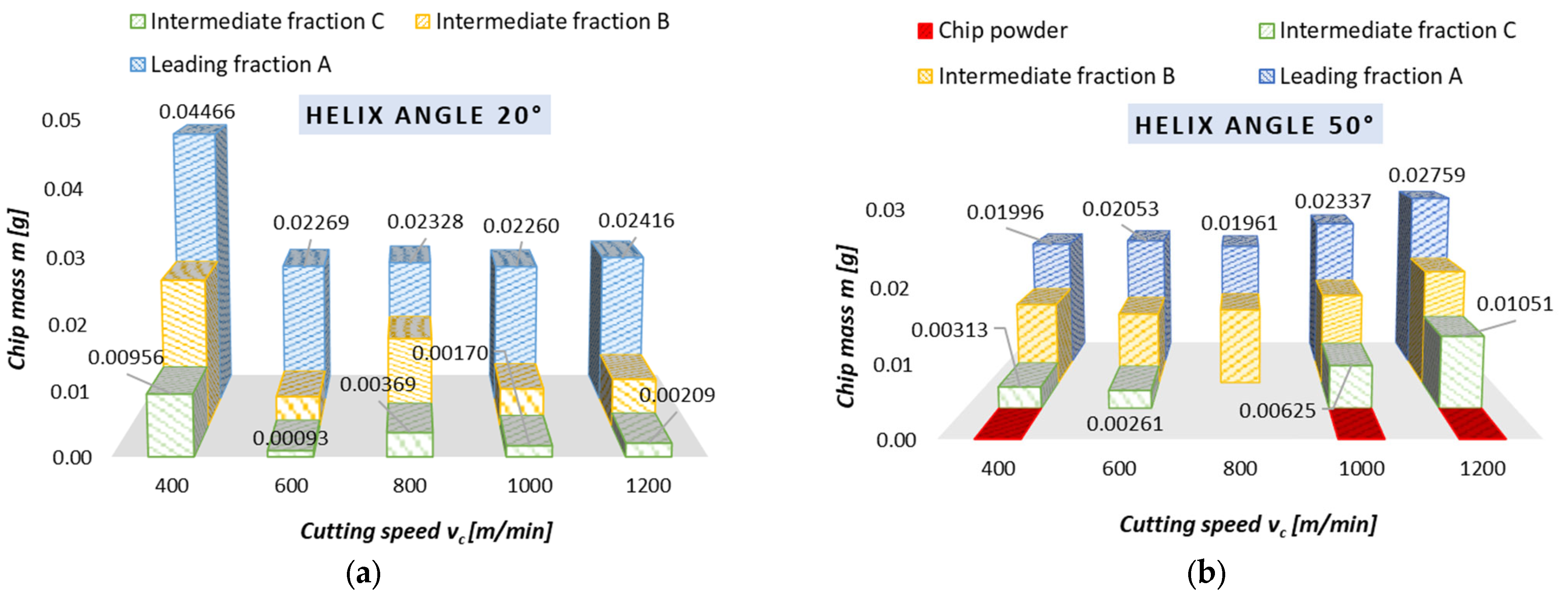
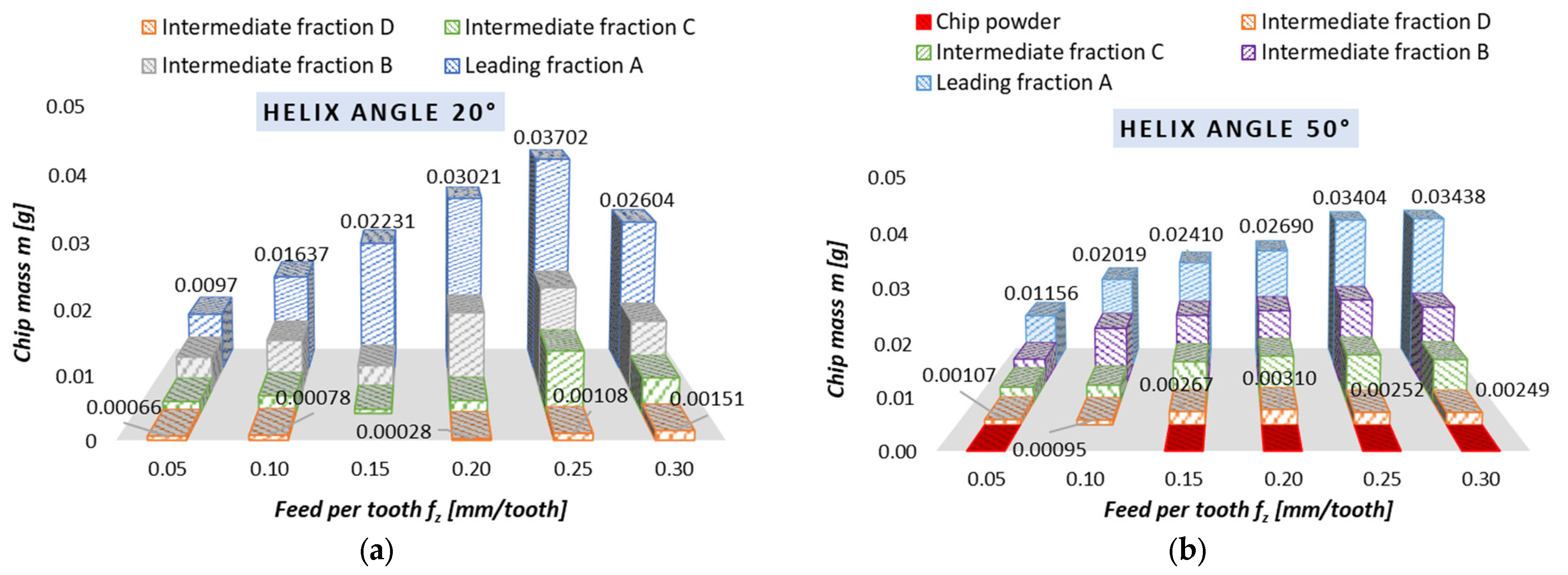
3.2. Chips Mass
- -
- there are 2 chip fractions (for a helix angle of 50° and vc of 800 m/min),
- -
- there are 3 chip fractions (for a helix angle of 20° and the entire tested range of vc, for fz of 0.15 mm/tooth, for a helix angle of 50° and vc of 600 m/min),
- -
- there are 4 fractions of chips (for a helix angle of 50° and fz of 0.10 mm/tooth).
3.3. Time to Ignition, Temperature of Ignition
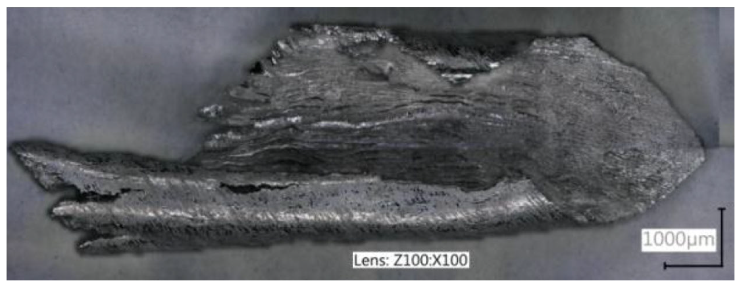
3.4. Chip Morphology, Chip Ignition Stages
4. Discussion
5. Conclusions
- -
- It is possible to implement safe, effective, as well as reliable dry milling of magnesium alloys, and therefore ensure safe maintenance of machine tools without a potential risk of damaging their components.
- -
- The best and most preferred machining conditions are those which generate only two or three chip fractions (e.g., full range vc and fz for 20° helix angle tool).
- -
- -
- The use of the 20° helix angle tool produces no chip powder, a product which is considered the most harmful and potentially dangerous chip fraction; this tool should therefore be the first choice for rough machining of magnesium alloys.
- -
- The most advantageous machining areas are those where the A fraction constitutes about 50% of the share in all chip fractions; this situation occurs for the entire vc range (without vc equal to 400 m/min) for λs = 20° and vc 400–800 m/min for λs = 50°; the range 0.05–0.20 mm/tooth for λs = 20° and for 0.05 and 0.15 mm/tooth for λs = 50°.
- -
- The unit mass of chips is an important indicator for estimating machining safety in terms of ignition susceptibility of individual chip fractions; unit chip mass of fraction A is within the following ranges: for vc and λs = 20—from 0.02260 to 0.04466 g; for vc and λs = 50°—from 0.01961 to 0.02759 g; for fz and λs = 20°—from 0.00970 to 0.03702 g; for fz and λs = 50°—from 0.01156 to 0.03438 g.
- -
- For the 50° helix angle tool, it was observed that the use of higher machining parameters led to a higher unit mass of leading fraction A (a similar trend was observed for the 20° helix angle tool and the feed of 0.25 mm/tooth).
- -
- The longest time to chip ignition was observed for leading fraction A, and it should be emphasized that the ignition of intermediate fraction D was not immediate (the chips ignited after approx. 1–3.5 s for the variable feed per tooth and after 2–4 s for the variable cutting speed), which is an important finding regarding ignition susceptibility and sudden ignition hazard when carrying out machining operations.
- -
- Both time to ignition as well as ignition temperature (determined outside of the milling machine, at a specially designed and constructed test stand) are important safety indicators, as they make it possible to estimate machining conditions that are considered safe working areas for a given machine tool.
- -
- The AZ91D alloy chip surfaces (obtained by SEM and metallographic examination) were free from ignition or intense oxidation products and had clearly outlined edges; hence, under the presented machining conditions, no risk of chip ignition was observed during machining.
Funding
Institutional Review Board Statement
Informed Consent Statement
Data Availability Statement
Conflicts of Interest
Abbreviations
| λs | Helix angle |
| vc | Cutting speed |
| fz | Feed per tooth |
| ap | Axial depth of cut |
| ae | Radial depth of cut |
| z | Number of blade, tooth |
| HSM | High speed machining |
| HSC | High speed cutting |
| HPC | High performance cutting |
| SEM | Scanning electron microscopy |
| Tav | Average temperature |
| Tmax | Maximum temperature |
| Fr. A | Chip fraction (leading A) |
| Fr. B | Chip fraction (intermediate B) |
| Fr. C | Chip fraction (intermediate C) |
| Fr. D | Chip fraction (intermediate D) |
References
- Semotiuk, L. An analysis of the operational characteristics of innovative tool structures used in high speed rough milling processes. Eksploat. I Niezawodn.-Maint. Reliab. 2009, 1, 46–53. [Google Scholar]
- Karimi, M.; Nosouhi, R. An experimental investigation on temperature distribution in high-speed milling of AZ91C magnesium alloy. AUT J. Mech. Eng. 2021, 5, 419–426. [Google Scholar] [CrossRef]
- Kryzhanivskyy, V.; Saoubi, R.M.; Ståhl, J.E.; Bushlya, V. Tool–chip thermal conductance coefficient and heat flux in machining: Theory, model and experiment. Int. J. Mach. Tools Manuf. 2019, 147, 103468. [Google Scholar] [CrossRef]
- Karaguzel, U.; Bakkal, M.; Budak, E. Modeling and Measurement of Cutting Temperatures in Milling. Procedia CIRP 2016, 46, 173–176. [Google Scholar] [CrossRef]
- Liu, C.; Liu, B.; Zhou, Y.; He, Y.; Chi, D.; Gao, X.; Liu, Q. A Real-Time Cutting Temperature Monitoring of Tool in Peripheral Milling Based on Wireless Transmission. Int. J. Therm. Sci. 2023, 186, 108084. [Google Scholar] [CrossRef]
- Ravi Kumar, N.V.; Blandin, J.J.; Suery, M.; Grosjean, E. Effect of alloying elements on the ignition resistance of magnesium alloys. Scr. Mater. 2003, 49, 225–230. [Google Scholar] [CrossRef]
- Zhou, H.; Li, W.; Wang, M.X.; Zhao, Y. Study on ignition proof AZ91D magnesium alloy chips with cerium addition. J. Rare Earth 2005, 23, 466–469. [Google Scholar]
- Lin, P.Y.; Zhou, H.; Li, W.; Li, W.P.; Sun, N.; Yang, R. Interactive effect of cerium and aluminum on the ignition point and the oxidation resistance of magnesium alloy. Corros. Sci. 2008, 50, 2669–2675. [Google Scholar] [CrossRef]
- Liu, M.; Shih, D.S.; Parish, C.; Atrens, A. The ignition temperature of Mg alloys WE43, AZ31 and AZ91. Corros. Sci. 2012, 54, 139–142. [Google Scholar] [CrossRef]
- Zagórski, I. Safety in Rough Milling of Magnesium Alloys Using Tools with Variable Cutting Edge Geometry. Adv. Sci. Technol. Res. J. 2023, 17, 181–191. [Google Scholar] [CrossRef]
- Habrat, D.; Stadnicka, D.; Habrat, W. Analysis of the legal risk in the scientific experiment of the machining of magnesium alloys. In Advances in Manufacturing Engineering and Materials; Hloch, S., Klichova, D., Krolczyk, G.M., Chattopadhyaya, S., Ruppenthalova, L., Eds.; Lecture Notes in Mechanical Engineering; Springer: Cham, Switzerland, 2019; pp. 421–430. [Google Scholar] [CrossRef]
- Gziut, O.; Kuczmaszewski, J.; Zagórski, I. Analysis of chip fragmentation in AZ91HP alloy milling with respect to reducing the risk of chip. Eksploat. I Niezawodn.-Maint. Reliab. 2016, 18, 73–79. [Google Scholar] [CrossRef]
- Gziut, O.; Kuczmaszewski, J.; Zagórski, I. Impact of depth of cut on chip formation in AZ91HP magnesium alloy milling with tools of varying cutting edge geometry. Adv. Sci. Technol. Res. J. 2015, 9, 49–56. [Google Scholar] [CrossRef] [PubMed]
- Kuczmaszewski, J.; Zagórski, I.; Gziut, O.; Legutko, S.; Krolczyk, G.M. Chip fragmentation in the milling of AZ91HP magnesium alloy. Stroj. Vestn.-J. Mech. Eng. 2017, 63, 628–642. [Google Scholar] [CrossRef]
- Legutko, S. Development trends in machines operation maintenance. Eksploat. I Niezawodn.-Maint. Reliab. 2009, 2, 8–16. [Google Scholar]
- Sahoo, S.K.; Sahoo, B.N.; Panigrahi, S.K. Investigation into machining performance of microstructurally engineered in-situ particle reinforced magnesium matrix composite. J. Magnes. Alloys 2023, 11, 916–935. [Google Scholar] [CrossRef]
- Skoczylas, A.; Kłonica, M. Selected Properties of the Surface Layer of C45 Steel Samples after Slide Burnishing. Materials 2023, 16, 6513. [Google Scholar] [CrossRef]
- Skoczylas, A.; Zaleski, K.; Zaleski, R.; Gorgol, M. Analysis of surface properties of nickel alloy elements exposed to impulse shot peening with the use of positron annihilation. Materials 2021, 14, 7328. [Google Scholar] [CrossRef]
- Kuczmaszewski, J.; Pieśko, P. Wear of milling cutters resulting from high silicon aluminium alloy cast AlSi21CuNi machining. Eksploat. I Niezawodn.-Maint. Reliab. 2014, 16, 37–41. [Google Scholar]
- Zgórniak, P.; Grdulska, A. Investigation of temperature distribution during milling process of AZ91HP magnesium alloys. Mech. Mech. Eng. 2012, 16, 33–40. [Google Scholar]
- Zgórniak, P.; Stachurski, W.; Ostrowski, D. Application of thermographic measurements for the determination of the impact of selected cutting parameters on the temperature in the workpiece during milling process. Stroj. Vestn.-J. Mech. Eng. 2016, 62, 657–664. [Google Scholar] [CrossRef]
- Cichosz, P.; Karolczak, P.; Waszczuk, K. Review of Cutting Temperature Measurement Methods. Materials 2023, 16, 6365. [Google Scholar] [CrossRef] [PubMed]
- Fang, F.Z.; Lee, L.C.; Liu, X.D. Mean flank temperature measurement in high speed dry cutting. J. Mater. Process. Technol. 2005, 167, 119–123. [Google Scholar] [CrossRef]
- Hou, J.; Zhao, N.; Zhu, S. Influence of Cutting Speed on Flank Temperature during Face Milling of Magnesium Alloy. Mater. Manuf. Process. 2011, 26, 1059–1063. [Google Scholar] [CrossRef]
- Le Coz, G.; Marinescu, M.; Devillez, A.; Dudzinski, D.; Velnom, L. Measuring temperature of rotating cutting tools: Application to MQL drilling and dry milling of aerospace alloys. Appl. Therm. Eng. 2012, 36, 434–441. [Google Scholar] [CrossRef]
- de Oliveira Moreira, M.; Abrão, A.M.; Ferreira, R.A.; Porto, M.P. Temperature Monitoring of Milling Processes Using a Directional-Spectral Thermal Radiation Heat Transfer Formulation and Thermography. Int. J. Heat Mass Transf. 2021, 171, 121051. [Google Scholar] [CrossRef]
- Masoudi, S.; Gholami, M.A.; Lariche, M.J.; Vafadar, A. Infrared temperature measurement and increasing infrared measurement accuracy in the context of machining process. Adv. Prod. Eng. Manag. 2017, 12, 353–362. [Google Scholar] [CrossRef]
- Guimarães, B.; Rosas, J.; Fernandes, C.M.; Figueiredo, D.; Lopes, H.; Paiva, O.C.; Silva, F.S.; Miranda, G. Real-Time Cutting Temperature Measurement in Turning of AISI 1045 Steel through an Embedded Thermocouple—A Comparative Study with Infrared Thermography. J. Manuf. Mater. Process. 2023, 7, 50. [Google Scholar] [CrossRef]
- Li, T.; Long, H.; Shi, T.; Yang, J.; Duan, J. Cutting temperature measurement using a novel near-infrared two-color pyrometer under dry and wet cutting of Ti-6Al-4V alloy. J. Mater. Process. Technol. 2022, 309, 117751. [Google Scholar] [CrossRef]
- Hou, J.; Zhou, W.; Zhao, N. Methods for prevention of ignition during machining of magnesium alloys. Key Eng. Mater. 2010, 447–448, 150–154. [Google Scholar] [CrossRef]
- Zhao, N.; Hou, J.; Zhu, S. Chip ignition in research on high-speed face milling AM50A magnesium alloy. In Proceedings of the 2nd International Conference on Mechanic Automation and Control Engineering, Inner Mongolia, China, 15–17 July 2011. [Google Scholar] [CrossRef]
- Han, D.; Zhang, J.; Huang, J.; Lian, Y.; He, G. A review on ignition mechanisms and characteristics of magnesium alloys. J. Magnes. Alloys 2020, 8, 329–344. [Google Scholar] [CrossRef]
- Akyuz, B. Machinability of magnesium and its alloys. Online J. Sci. Technol. 2011, 1, 31–38. [Google Scholar]
- Guo, Y.B.; Salahshoor, M. Process mechanics and surface integrity by high-speed dry milling of biodegradable magnesium–calcium implant alloys. CIRP Ann.-Manuf. Technol. 2010, 59, 151–154. [Google Scholar] [CrossRef]
- Guo, Y.; Liu, Z. Sustainable High Speed Dry Cutting of Magnesium Alloys. Mater. Sci. Forum Online 2012, 723, 3–13. [Google Scholar] [CrossRef]
- PN-ISO 3685:1996; Tool-Life Testing with Single-Point Turning Tools. SMC, Sektor Maszyn i Inżynierii: Pass, Poland, 1996. (In Polish)
- ISO 3685:1993; Tool-Life Testing with Single-Point Turning Tools. International Organization for Standardization: Geneva, Switzerland, 1993.


| Machining Conditions | Research Object, Machinability Indicators | Reference |
|---|---|---|
| Dry Rough Down End-Milling (different helix angles): ap = 0.5–6.0 mm, fz = 0.15 mm/tooth, vc = 800 m/min, ae = 14 mm | Fractions of chips and their metallographic images, chip mass, percentage share of chip fractions, time to ignition, ignition temperature, stages preceding chip ignition | [10] |
| Dry Rough Down End-Milling (different rake angles): ap = 0.5–3.0 mm, fz = 0.05–0.30 mm/tooth, vc = 400–1200 m/min, ae = 14 mm | Fractions of chips and their metallographic images, chip mass, dimensions | [12] |
| Dry Rough Down End-Milling (different rake angles): ap = 0.5–3.0 mm, fz = 0.05 and 0.15 mm/tooth, vc = 800 m/min, ae = 14 mm | Fractions of chips and their metallographic images | [13] |
| Dry Rough Down End-Milling (different rake angles): ap = 6.0 mm, fz = 0.05–0.30 mm/tooth, vc = 400–1200 m/min, ae = 14 mm | Fractions of chips and their metallographic images, chip mass, percentage share of chip fractions, dimensions of chips, share of individual fractions in the total chip population | [14] |
| Type of Chip Fraction | Cutting Speed vc [m/min] | ||||
|---|---|---|---|---|---|
| 400 | 600 | 800 | 1000 | 1200 | |
| Leading fraction A |  |  |  |  |  |
| Intermediate fraction B |  |  |  |  |  |
| Intermediate fraction C |  |  |  | 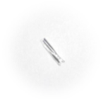 | 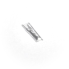 |
| Intermediate fractions D | None | None | None | None | None |
| Chip powder | None | None | None | None | None |
| Type of Chip Fraction | Cutting Speed vc [m/min] | ||||
|---|---|---|---|---|---|
| 400 | 600 | 800 | 1000 | 1200 | |
| Leading fraction A | 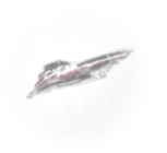 | 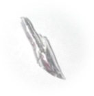 | 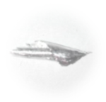 | 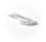 | 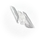 |
| Intermediate fraction B | 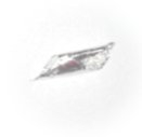 |  |  |  |  |
| Intermediate fraction C |  |  | None |  |  |
| Intermediate fraction D | None | None | None | None | None |
| Powder chip | 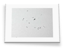 | None | None | 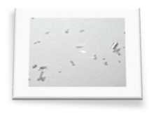 | 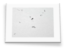 |
| Type of Chip Fraction | Feed per Tooth fz [mm/tooth] | |||||
|---|---|---|---|---|---|---|
| 0.05 | 0.10 | 0.15 | 0.20 | 0.25 | 0.30 | |
| Leading fraction A |  | 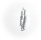 | 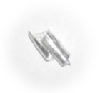 | 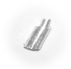 | 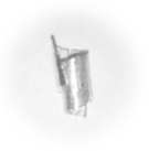 |  |
| Intermediate fraction B | 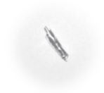 | 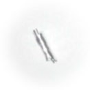 | 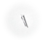 | 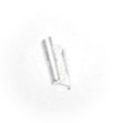 |  | 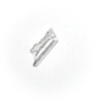 |
| Intermediate fraction C |  |  |  |  |  |  |
| Intermediate fraction D |  |  | None |  |  |  |
| Powder chip | None | None | None | None | None | None |
| Type of Chip Fraction | Feed per Tooth fz [mm/tooth] | |||||
|---|---|---|---|---|---|---|
| 0.05 | 0.10 | 0.15 | 0.20 | 0.25 | 0.30 | |
| Leading fraction A |  |  |  | 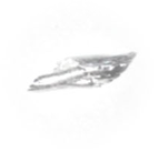 | 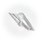 |  |
| Intermediate fraction B | 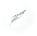 | 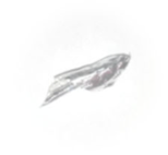 |  |  |  |  |
| Intermediate fraction C |  |  |  |  |  |  |
| Intermediate fraction D |  | 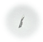 |  |  |  |  |
| Powder chip |  | None | 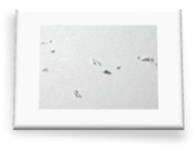 | 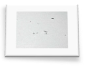 |  | 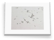 |
Disclaimer/Publisher’s Note: The statements, opinions and data contained in all publications are solely those of the individual author(s) and contributor(s) and not of MDPI and/or the editor(s). MDPI and/or the editor(s) disclaim responsibility for any injury to people or property resulting from any ideas, methods, instructions or products referred to in the content. |
© 2025 by the author. Licensee MDPI, Basel, Switzerland. This article is an open access article distributed under the terms and conditions of the Creative Commons Attribution (CC BY) license (https://creativecommons.org/licenses/by/4.0/).
Share and Cite
Zagórski, I. Machining Safety in Dry Rough Milling of Casting Magnesium Alloy AZ91D Using Carbide End Mills with Different Geometries. Materials 2025, 18, 1104. https://doi.org/10.3390/ma18051104
Zagórski I. Machining Safety in Dry Rough Milling of Casting Magnesium Alloy AZ91D Using Carbide End Mills with Different Geometries. Materials. 2025; 18(5):1104. https://doi.org/10.3390/ma18051104
Chicago/Turabian StyleZagórski, Ireneusz. 2025. "Machining Safety in Dry Rough Milling of Casting Magnesium Alloy AZ91D Using Carbide End Mills with Different Geometries" Materials 18, no. 5: 1104. https://doi.org/10.3390/ma18051104
APA StyleZagórski, I. (2025). Machining Safety in Dry Rough Milling of Casting Magnesium Alloy AZ91D Using Carbide End Mills with Different Geometries. Materials, 18(5), 1104. https://doi.org/10.3390/ma18051104