Article

The Investigation of Ni-Doped SrFeO3−δ Perovskite for a Symmetrical Electrode in Proton Ceramic Fuel Cells

1
School of Materials Science and Engineering, Xi’an University of Technology, Xi’an 710048, China
2
Center of Nanomaterials for Renewable Energy, State Key Laboratory of Electrical Insulation and Power Equipment, Xi’an Jiaotong University, Xi’an 710049, China
3
Hengtong Group, Suzhou 215200, China
*
Author to whom correspondence should be addressed.
Materials 2025, 18(7), 1460; https://doi.org/10.3390/ma18071460
Submission received: 31 January 2025 / Revised: 3 March 2025 / Accepted: 10 March 2025 / Published: 25 March 2025

Abstract

:
The development of symmetrical solid oxide fuel cells with identical cathode and anode is beneficial for thermal matching and reducing the cost. Herein, proton-conducting electrolyte and novel high catalytic activity electrode material for symmetrical solid oxide fuel cells are proposed. Ni-doping at the B-site of (Sr0.8Ce0.2)0.95FeO3−δ (SCF) indicates reduced cell edge lengths, cell volume, and a more porous honeycomb structure. The B-site elements in oxide tend to have a high oxidation state via Ni-doping. Simple doping modification in SCF causes better thermal matching between the electrode and electrolyte and form more oxygen vacancies at the operating temperature. At the anode side, Ni-doping improves the stability of the symmetric electrode in reducing the atmosphere. The polarization resistance of symmetrical cells for new electrode material is half of the original both in oxidation and reduction atmosphere, which indicates boosted electrochemical performance for the cathode and anode. At the same time, Ni-doping reduces the impedance activation energy of the anode reaction in symmetric cells. The output performance of the cell is 210.4 mW·cm−2 at 750 °C and the thickness of the electrolyte is 400 μm, achieving a highly efficient symmetrical electrode in proton ceramic fuel cells. The new finding of materials provides a novel high efficiency symmetrical electrode and proposes guidance for the improvement of solid oxide fuel cells at a reduced temperature.

1. Introduction

The rapid development of society depends on energy conversion devices. Solid oxide fuel cells (SOFCs) have been considered one of the most promising devices for direct conversion of chemical energy in fuel into electricity with high energy efficiency and low emissions [1,2,3,4]. However, the high operating temperature (800–1000 °C) of SOFCs leads to the mismatch of components, long start-up times, strict material requirements, and high prices [5,6,7,8]. It seriously hinders the commercial application of SOFCs. The traditional SOFC is based on an oxygen ion conducting electrolyte, which demands a high operating temperature [9,10,11,12]. The main reason is that the thermo-activation reactions of the oxygen ion conducting electrolyte requires high temperatures [13,14,15,16]. Currently, a proton-conducting electrolyte replaces the oxygen ion conducting electrolyte for greater proton mobility to design proton ceramic fuel cells (PCFCs), which effectively reduced the operating temperature [17,18,19,20]. Therefore, current research is focusing on finding high catalytic and thermal matching electrodes for PCFCs.
The perovskites in ABO3 type are favorable candidates for electrodes in PCFCs [21,22,23]. Generally, the A-site is large cations such as rare-Earth or alkaline-Earth elements and the B-site is transition elements with smaller ionic radius. The ABO3 perovskites possess a special framework of [BO6] octahedra and structural stability under a reducing or oxidizing atmosphere, which are employed as symmetrical electrode materials for SOFCs [24,25,26]. Perovskite oxide SrFeO3−δ exhibits excellent redox properties in oxygen exchange applications, including oxygen separation and chemical cycling for oxygen production. However, its kinetics are insufficient at lower temperatures [27,28,29,30]. The oxidation reaction rate may be limited by diffusion in the bulk, while the reduction reaction rate is limited by surface reactions. By doping minor Ca at A-site, Sr0.93Ca0.07Fe0.9Co0.1O3−δ indicates an increased oxidation rate by four times [31]. Yao et al. employed Ta5+ and Mo6+ co-doped at the B-site of SrFeO3−δ perovskite as cathodes for intermediate temperature SOFC, which indicates the increased number of oxygen vacancies in the material and better electrochemical performance of the cell [32]. The W-doped SrFeO3−δ of SrFe0.8W0.2O3−δ perovskite oxide prepared by Liu et al. was applied as an electrode material for symmetric solid oxide fuel cells. W-doping not only stabilizes the cubic perovskite structure of SrFeO3−δ but also increases its resistance to reducing atmospheres [33]. Ce-doping at the A-site of SrFeO3−δ increases its structural stability in a reducing atmosphere, and SSOFCs with Ce/Ru co-doped exhibit excellent electrochemical performance [34].
In this regard, a proton-conducting electrolyte instead of the traditional oxygen ion conducting electrolyte is employed, seeking a symmetrical electrode material with high catalytic activity. The novel symmetrical electrode material of Ni-doping at B-site of (Sr0.8Ce0.2)0.95FeO3−δ is designed with a porous honeycomb structure, which is beneficial for gas transport and reaction. Via Ni-doping, the B-site elements tend to have a high oxidation state, which can form more oxygen vacancies for oxygen transport during oxygen reduction reaction at the cathode side. Furthermore, Ni-doping is expected to be realized as a better matched thermal expansion coefficient between the electrode and electrolyte. In an attempt to explore the process of electrochemical reaction, the polarization resistance and output performance of the cell is investigated to provide a novel high efficiency symmetrical electrode material and guidance for achieving low- temperature PCFCs.

2. Experimental and Analysis

2.1. Materials Synthesis

The target compositions of the symmetrical electrode materials (Sr0.8Ce0.2)0.95FeO3−δ (SCF) and (Sr0.8Ce0.2)0.95Fe0.9Ni0.1O3−δ (SCFN) powders were synthesized by the sol–gel method of citric acid-nitrate. Stoichiometric amounts of Sr(NO3)2 (99.5% Aladdin, Wuhan, China), Ce(NO3)3·6H2O (99.0% Aladdin, China), Fe(NO3)3·9H2O (98.5% Aladdin, China), and Ni(NO3)2·6H2O (99.5% Sinopharm Group, Shanghai, China) were dissolved in deionized water for the compositions of SCF and SCFN. Citric acid with the molar ratio of the total metal in 2:1 was added into the solution. Then, the solution was continuously stirred and heated to form a gelatinous state. The xerogel was sintered at 600 °C for the burning of citric acid and calcined at 950 °C for 10 h in air to yield the final perovskites. The specific experimental process is shown in Figure 1.

2.2. Cell Fabrication

BaZr0.1Ce0.7Y0.2O3 (BZCY) powder for the electrolyte was synthesized by the solid reaction method. First, stoichiometric amounts of BaCO3 (99.9% Aladdin, China), ZrO2 (99.99% Aladdin, China), CeO2 (99.99% Aladdin, China), and Y2O3 (99.99% Sinopharm Group, China) were mixed well by ball milling, and the mixture was sintered at 1200 °C for 10 h. The pre-sintering powder was pressed into a disk under a pressure of 10 MPa and calcined at 1450 °C for 10 h to obtain the dense electrolyte disk. To fabricate the symmetric cells, the powders of SCF and SCFN were mixed uniformity with terpilenol and turpentine and then screen-printed on both sides of a BZCY disk and sintered at 950 °C for 4 h; the current collector was formed by silver paste sintered on both sides of the electrolyte. The sample bars used for the dilatometer test are prepared by dry pressing and a solid reaction method at 1300 °C.

2.3. Characterization

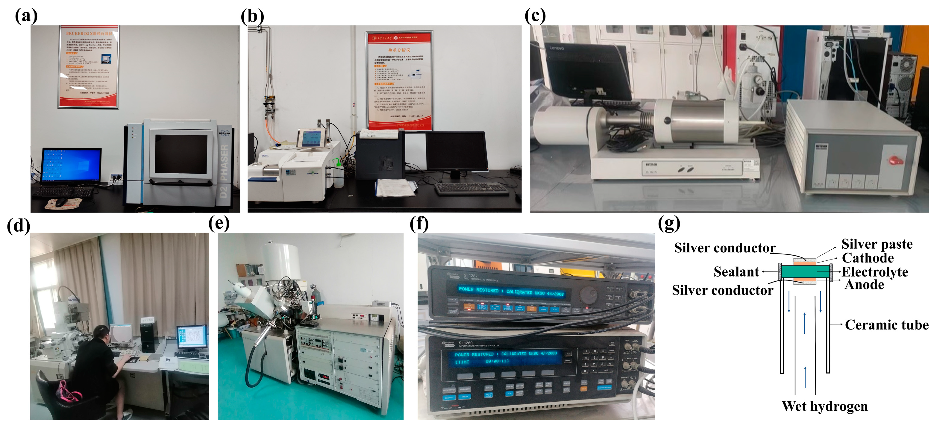
X-ray diffraction (XRD, Berlin, Germany, Bruker D2 PHASER) patterns of the prepared samples were conducted in the 2θ range of 20–80° operated at a step of 0.02° using Cu tube, as well as the mixture of electrodes and electrolyte sintered at 950 °C in air and 5%H2. Thermogravimetric (TGA, Mettler Toledo, Greifensee, Switzerland) analyses were performed from room temperature to 800 °C in oxygen with a heating rate of 5 °C·min−1. Thermal expansion coefficients (TECs) of the symmetrical electrodes and the electrolyte were measured by dilatometer (DIL 402C, Netzsch, Selb, Germany) to evaluate the compatibility between the electrolyte and electrode. The morphologies of the electrode powders and the interface of the cell were performed by scanning electron microscopy (SEM, KEYENCE VE-9800, Osaka, Japan). X-ray photoelectron spectroscopy (XPS, Thermo Scientific K-Alpha, Waltham, MA, USA) was performed to determine the different valences of the elements in the samples before and after reduction. The relevant experimental instruments are shown in Figure 2a–e. Electrochemical impedance spectroscopy (EIS) is one of the most commonly used tools for studying electrochemical systems. The impedance spectrum can be analyzed by the equivalent circuit, that is, the circuit diagram composed of some electrical components is fitted to the behavior of the electrochemical system and a series of parameters such as polarization resistance are obtained. Figure 2f shows Solartron 1260–1287, an electrochemical workstation used for testing electrochemistry in this paper. It characterizes AC impedance spectra under different atmospheres and ambient temperatures and uses Z-view software (Z-view 3.0a) attached to the instrument to analyze and fit the collected impedance spectra data. The electrochemical impedance spectra of the symmetrical cell are typically measured by an electrochemical workstation in the frequency range from 0.1 Hz to 1 MHz under an applied amplitude of 10 mV. The cell performance was tested by an electrochemical workstation by using air as the oxidant and wet H2 as the fuel. The symmetrical cell is fixed at one end of the high temperature ceramic tube, sealed with a high temperature inorganic adhesive, and the sealed battery is placed in the air for curing for at least 24 h, as shown in Figure 2g. Run the high temperature furnace at a heating rate of 2 °C·min−1 to slowly heat up to the cell test temperature to prevent the cracking of high temperature inorganic glue. After ensuring the air tightness of the test device, wet H2 is used as the fuel gas for the anode side, and static air is used as the oxidizing agent for the cathode side. The electrochemical workstation is used to test the output performance of the cell. The output voltage (V) and current (I) of the cell are measured. The power density P can be calculated by the Formula (1) as follows:
P = V I / S
where P is the output power density of a single cell (mW·cm−2); I is the output current (mA); V is the working voltage (V); and S is the effective working area (cm2) of the cell.

3. Result and Discussion

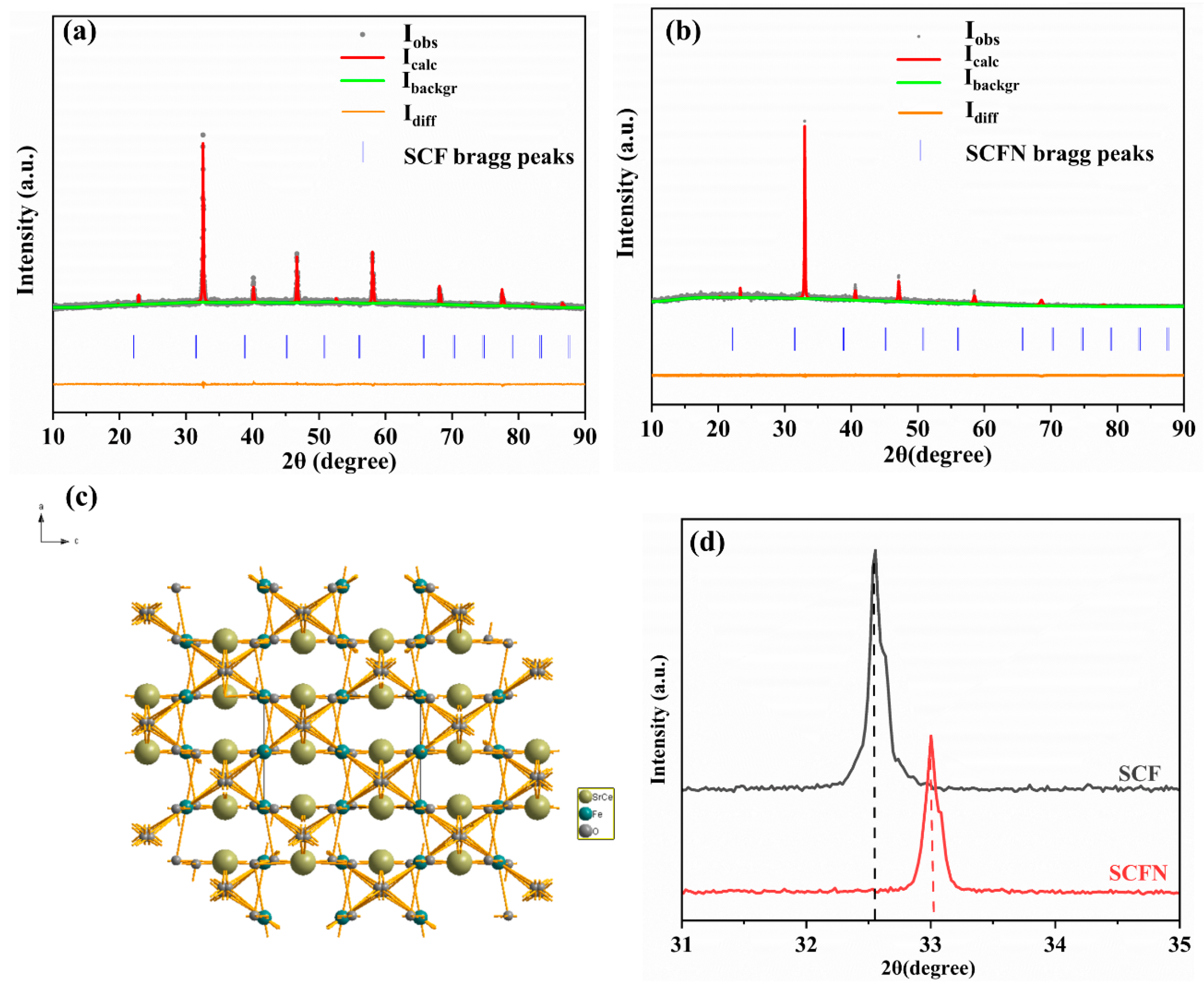
Figure 3a,b displays the X-ray diffraction pattern and the full profile refinements of SFC and SCFN, indicating orthorhombic structure (Figure 3c) sintering in air at 950 °C for 10 h. That is, Fe ions at the B-site were successfully replaced by Ni ions in (Sr0.8Ce0.2)0.95FeO3−δ. The main peaks of the XRD pattern can be indexed by SrFeO3−x (JCPDS No.34-0641), belonging to space group Pbnm (62). The cell parameters, cell volume, and other information obtained by XRD refinement are listed in Table 1. Via Ni-doping at the B-site, the cell edge lengths a, b, and c of the ABO3 type perovskite were reduced, and the cell volume decreased from 235.9 Å3 to 234.7 Å3. Furthermore, the XRD peak of SCF at around 32.6° is slightly shifted to the right by 33.0° for SCFN with Ni-doping shown in Figure 3d. As ionic radii of Ni are smaller than those of Fe, the results are in accordance with the Vegard’s rule of the lattice volume. This further confirms that the ion valence state at the B-site is demonstrated in the XPS analysis.
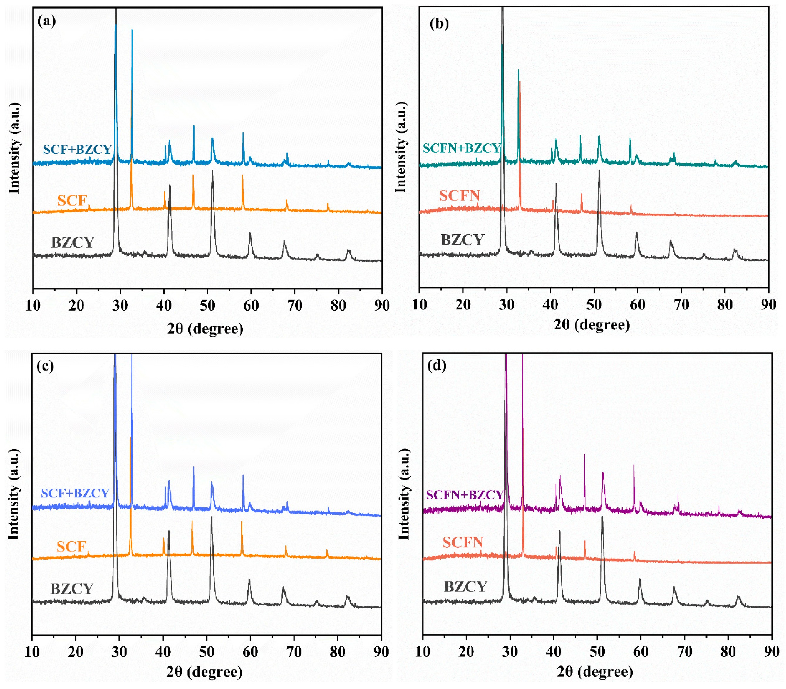
The chemical compatibility between the electrode and electrolyte in the oxidizing/reducing atmosphere is analyzed in Figure 4. The XRD patterns of the symmetrical electrode material, electrolyte and the mixture of the electrode and the electrolyte sintered at 950 °C in air for 6 h are shown in Figure 4a,b. The XRD of the symmetrical electrode, electrolyte and the mixture of the electrode and the electrolyte sintered in 5%H2 at 950 °C for 6 h are shown in Figure 4c,d, respectively. The results show that, both for SCF and SCFN, the XRD patterns of the mixture undergoing high temperatures are the superposition of the diffraction peaks of the cathode and electrolyte. Obviously, no new impurity peaks appear. This indicates excellent chemical compatibility between the cathodes and electrolyte BZCY.
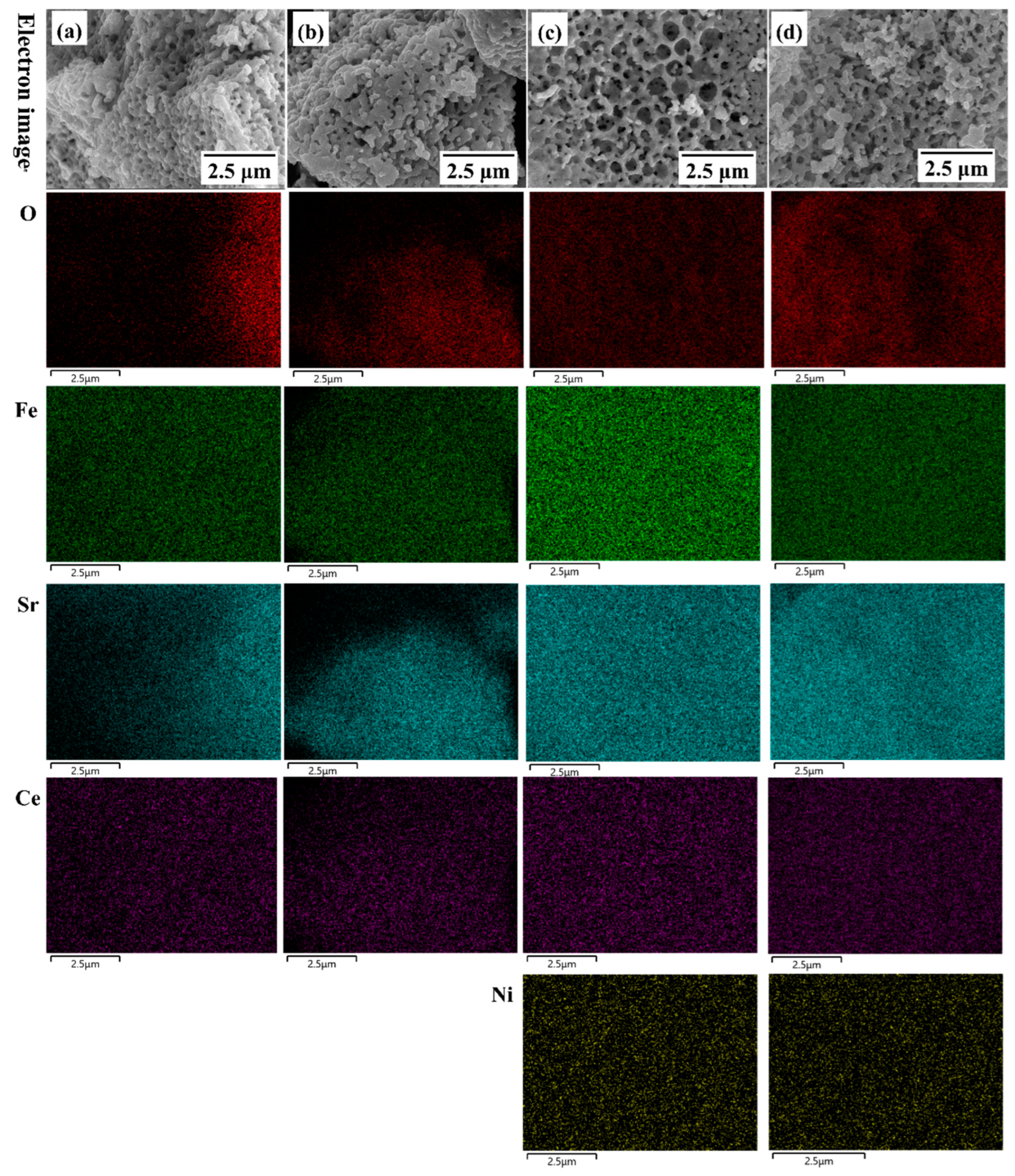
The SEM and Energy Dispersive X-ray Spectroscopy (EDS) mappings for SCF and SCFN before and after the reduction reaction are shown in Figure 5, where, in general, the elements are distributed uniformly in the electrode. Via Ni-doping at the B-site, the electrode material presents a more porous honeycomb structure, which is conducive to the gas transport during the reaction process. As shown in Table 2, the atomic percents for SCF is 53.3%, 24.0%, 18.0%, and 7.3% for O, Fe, Sr, and Ce before reduction. The reduction reaction resulted in a significant decrease in the surface elements of O, Sr, and Ce, and a significant increase in Fe. For SCFN, the atomic percents are 53.7%, 21.1%, 18.3%, 4.5%, and 2.5% for O, Fe, Sr, Ce, and Ni before reduction. The reduction reaction resulted in a slight decrease in O, a slight increase in Fe, and the atomic ratios of the other elements barely changed. This indicates that Ni-doping not only accelerates the gas transport of the redox reaction process, but also facilitates the stability of the electrode material in the reducing atmosphere.
Thermal compatibility is a critical issue between the electrode and electrolyte. It can be evaluated by the material thermal expansion coefficient (TEC). Figure 6a shows the instantaneous TEC of the electrode and electrolyte in air. This indicates that the TEC of BZCY fluctuates in the range of 8.0–13.0 × 10⁻⁶ K−1. The TEC of SCFN is increased with rising temperature at the operating temperature (600–750 °C) in the range of 14.3–16.8 × 10⁻⁶ K−1. Compared with SCF, the difference in TEC between SCFN and BZCY is relatively small, implying that Ni-doping SCF at the B-site improves the thermal match with the BZCY electrolyte. According to TG analysis in Figure 6b, SCF and SCFN indicate a minor increase in mass from room temperature to 200 °C, which is derived from the adsorption of reaction gas O2 by porous cathode materials. Above 200 °C, both SCF and SCFN exhibit accelerated mass reduction, with mass percents of 99.4% and 99.1%, respectively. As the temperature rises, the B-site metal oxides are reduced and lattice oxygen escapes, forming oxygen vacancies. The formation of oxygen vacancies accelerates the diffusion and migration of oxygen at the cathode side, thereby enhancing the electrocatalytic activity. Compared with SCF, Ni-doping at the B-site leads to an increase in weight loss, which is beneficial for the formation of oxygen vacancies.
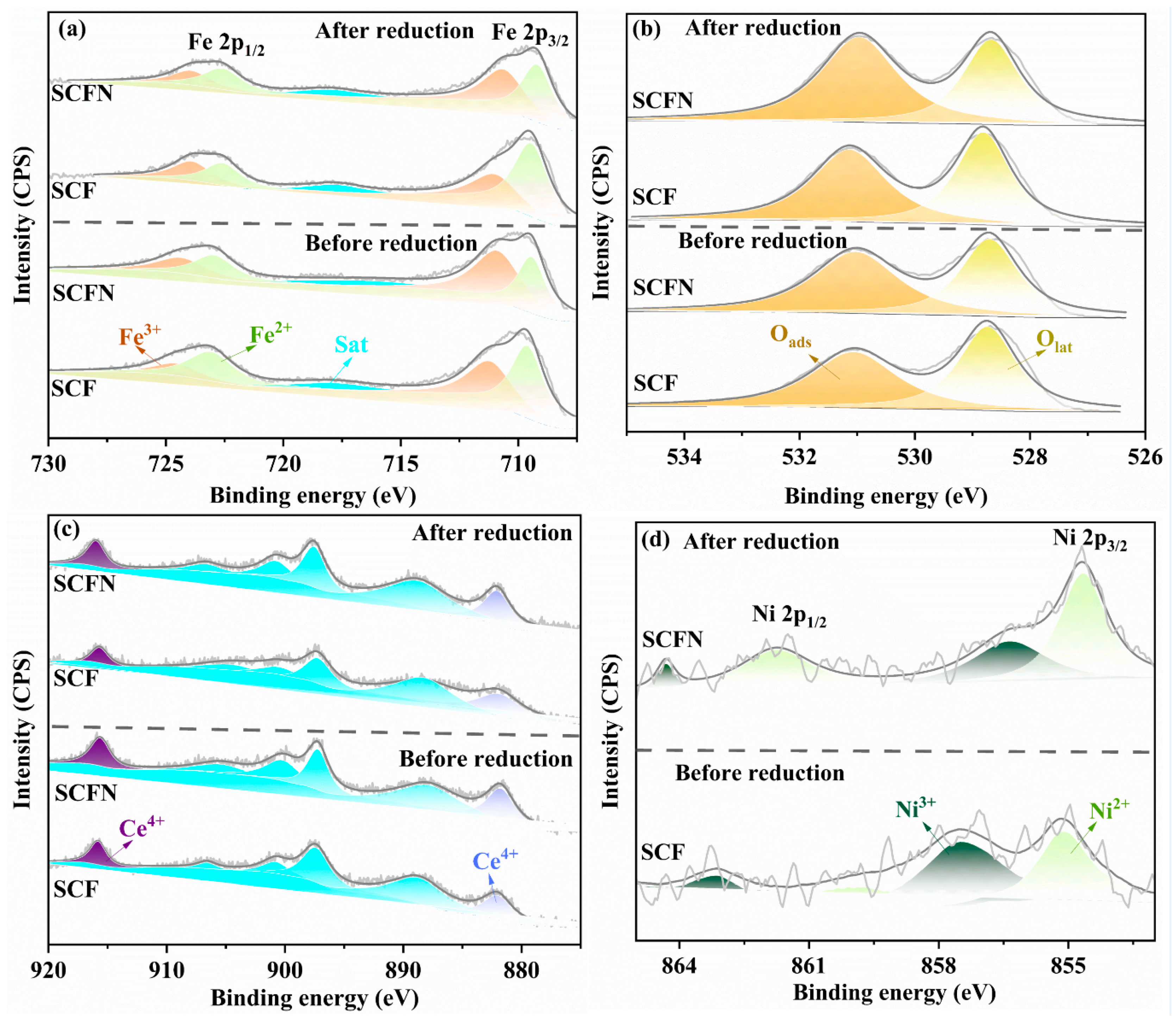
The XPS spectra of the as-prepared and reduced samples of SCF and SCFN were analyzed to study the chemical composition and valence states of the elements. As shown in Figure 7a, there are two distinct peaks in Fe 2p, Fe 2p1/2 and Fe 2p3/2, which contain Fe2+ and Fe3+. For Fe 2p1/2, peaks with higher binding energies are assigned to Fe3+, while peaks with lower binding energies belong to Fe2+. For Fe 2p3/2, the peak with high binding energy belongs to Fe3+, while the peak with low binding energy is assigned to Fe2+. Figure 7b shows the XPS of O 1s. The peak with higher binding energy is approximately 531 eV, which represents lattice oxygen (Olat) bound to metal atoms, while the relatively lower peak represents surface adsorbed oxygen (Oads) at approximately 529 eV. The characteristic peak at 916 eV could be related to the presence of Ce4+, while the low energy one at 882 eV could be related to the presence of Ce3+ in Figure 7c. There are two peaks in Ni 2p for SCFN in Figure 7d, Ni 2p1/2 and Ni 2p3/2. For Ni 2p1/2, the peak with the higher binding energy is assigned to Ni3+, while the peak with the lower binding energy belongs to Ni2+. For Ni 2p3/2, the peak with the high binding energy belongs to Ni3+, while the peak with the low binding energy is assigned to Ni2+.
The specific valence states of the elements are shown in Table 3. It indicates that the ions tend achieve to high valence states via Ni-doping, where the content of Fe3+and Ce4+ increases, as well as Olat. During high temperature operation of the cell, the reduction in B-site metal oxides and the escape of lattice oxygen lead to the formation of oxygen vacancies. The presence of oxygen vacancies is beneficial for increasing the migration rate of oxygen in the cathode material, thereby enhancing the electrochemical activity of the material. Ni-doping causes the oxidation state of the B-site elements to tend towards high oxidation states, making them prone to reduction reactions. Moreover, it increases the lattice oxygen content of the material, which can efficiently improve the electrochemical reaction activity of the cathode side. Compared with the XPS results of the reduced materials, in general, the reduction reaction causes the elements to tend towards a lower valence state. Ni-doping reduces the reduction in high valence elements and lattice oxygen in the material, which helps to improve the stability of the material during anodic reactions. Moreover, for O 1s, the reduction reaction tends to reduce Oads on the surface rather than Olat.
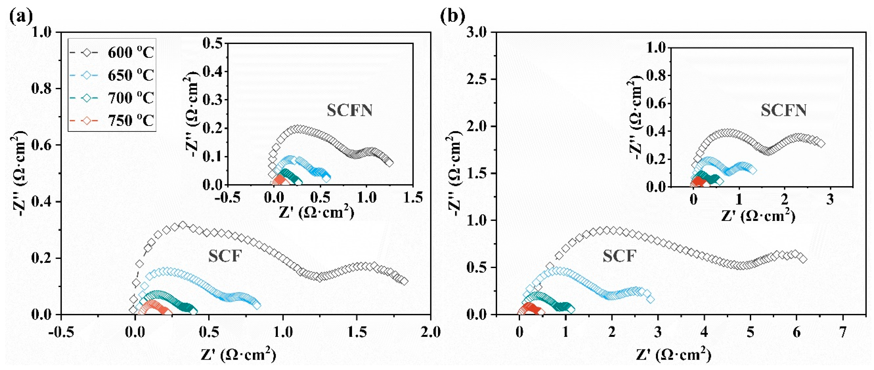
The study on electrochemical impedance performance of the symmetrical electrode was conducted with the electrolyte of BZCY, which is shown in Figure 8a,b. In general, the impedance decreases as the temperature increases. In air, the polarization resistance (Rp) of SCF and SCFN is 0.22 and 0.13 Ω cm2 at 750 °C. In 5%H2, the Rp of SCF and SCFN is 0.50 and 0.28 Ω cm2 at 750 °C. Compared with SCF, the Rp of SCFN is reduced for both the operated anode and cathode, which is derived from Ni-doping SCF at the B-site and induced the generation of new catalysts. The specific electrochemical impedance parameters are displayed in Table 4. The results suggest that Ni-doping SCF at the B-site not only improves the thermal match with the electrolyte but also optimized electrochemical reactions. In general, the Ce/Ni co-doped (Sr0.8Ce0.2)0.95Fe0.9Ni0.1O3−δ would be a promising symmetrical electrode for PCFCs.
As shown in Figure 9a,b, the activation energies (Ea) of polarization resistance for SCF and SCFN in air and 5%H2 were calculated by Arrhenius plots as follows:
log R p = log R 0 E a 2.303 R T
where Ro is the pre-exponential factor, T is the absolute temperature (K), and R is the molar gas constant (8.314 J mol−1K−1) [35]. In air, the Ea of polarization resistance for SCF is equal to the Ea for SCFN, which is 1.20 eV. This indicates that Ni-doping at the B-site has no impact on the Ea of polarization resistance. Instead, it only contributes to the gas transport and the formation of oxygen vacancies in the oxygen reduction reaction process. In 5%H2, the Ea of polarization resistance reduces via Ni-doping from 1.37 eV to 1.30 eV. That is, Ni-doping at the B-site is not only conducive to the gas transfer and oxidation reaction at the anode side, but also reduces the Ea of polarization resistance, which accelerates the hydrogen oxidation reaction of the interface between anode/electrolyte.
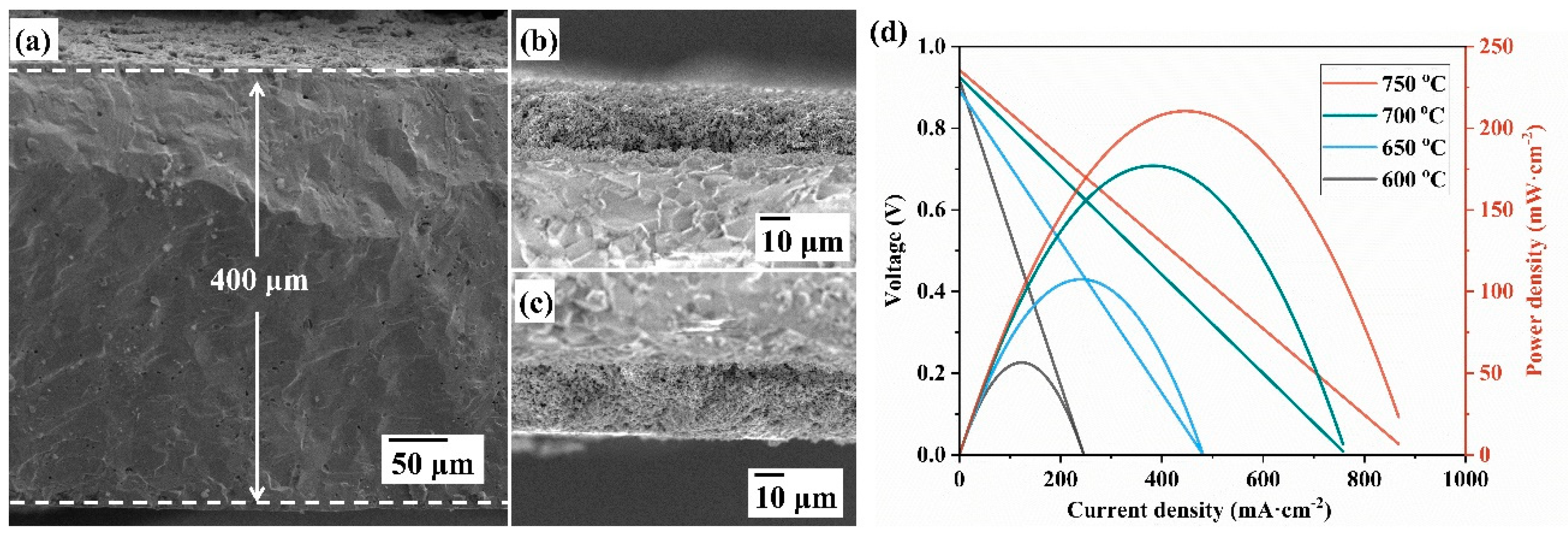
As shown in Figure 10a–c, the three-layer structure of the electrolyte supported symmetrical cell is composed of a porous cathode, dense electrolyte, and porous anode, with the thickness of electrolyte being 400 μm. To further assess the electrocatalytic activity of the symmetrical electrode, the symmetrical cell SCFN-BZCY|BZCY|SCFN-BZCY was operated in hydrogen and static air in Figure 10d. The open circuit voltage of the cell is at the range of 0.90–0.94 V, which indicates favorable gas tightness at the operating temperature. The current densities are 248.8, 484.2, 757.8, and 867.6 mA·cm−2 and the corresponding peak power densities are 56.5, 107.5, 177.0, and 210.4 mW·cm−2 at 600, 650, 700, and 750 °C. Considering the 400 μm thickness of the electrolyte derived from electrolyte supported symmetrical cell, the output performance is available, which is comparable to the SOFC with the Sr0.8Ce0.2FeO3−δ symmetrical electrode (260.4 mW·cm−2, the thicken ss of electrolyte La0.8Sr0.2Ga0.8Mg0.2O3−δ is 320 μm) [34]. It is worth noting that the more excellent performance may be realized by reducing the thickness of the electrolyte and optimizing the electrode technology, such as enhancing electrode performance by surface modification through the impregnation method, electro-spray deposition (ESD) [36], physical vapor deposition (PVD) [37,38], and atomic layer deposition (ALD) [39,40]. The best performance is 210.4 mW·cm−2 at 750 °C as the thickness of electrolyte BZCY is 400 μm, which illustrates that the material SCFN is supposed to be an excellent symmetrical electrode for PCFCs. The new finding provides a novel high efficiency symmetrical electrode material and guidance for achieving low-temperature PCFCs.

4. Conclusions

In summary, a novel symmetrical electrode of Ni-doped (Sr0.8Ce0.2)0.95FeO3−δ is developed for PCFCs, with a porous honeycomb structure and matched thermal expansion coefficient with a proton-conducting electrolyte. Via Ni-doping at the B-site, (Sr0.8Ce0.2)0.95Fe0.9Ni0.1O3−δ indicates reduced cell edge lengths, with the cell volume belonging to the space group Pbnm (62). The B-site elements in oxide tend to have a high oxidation state via Ni-doping, which is beneficial for forming more oxygen vacancies at high temperature and accelerating the cathodic oxygen reduction reaction. At the anode side, Ni-doping improves the stability of the symmetric electrode in the reducing atmosphere. The Rp of the symmetrical cell SCFN-BZCY|BZCY|SCFN-BZCY at 750 °C is 0.13 Ω cm2 and 0.28 Ω cm2, which is in air and 5%H2. Compared with the symmetrical cell of SCF, the Rp at 750 °C is 0.22 and 0.50 Ω cm2 in air and 5%H2, respectively. The Rp in the oxidation/reduction atmosphere reduced to half via Ni-doping. Meanwhile, Ni-doping reduces the Ea of impedance for the anode reaction in the symmetric cell. The peak power density of the symmetrical cell of SCFN is 210.4 mW·cm−2 at 750 °C. Since it is an electrolyte supported cell, electrochemical performance is already quite excellent considering the electrolyte thickness (400 μm), which demonstrated that Ni-doped SrFeO3−δ is a promising symmetrical electrode for proton ceramic fuel cells, which is the guidance for the development of solid oxide fuel cells at reduced temperature.

Author Contributions

Methodology, Z.Z.; Investigation, J.C., Y.S., H.W. and Z.L.; Data curation, C.Y.; Writing—original draft, J.C.; Writing—review&editing, J.C.; Supervision, K.W. and J.Z. All authors have read and agreed to the published version of the manuscript.

Funding

Financial support from the Natural Science Basic Research Program of Shaanxi (Grant No:2023-JC-QN-0559; 2023-JC-QN-0483), the State Key Laboratory of Electrical Insulation and Power Equipment (EIPE22314, EIPE22306), the School doctoral initiation fund (Gtant No: 256082008), the Scientific and technological projects entrusted by enterprises and institutions (Grant No: 441223068), and the Science and Technology Project of Xi’an High Voltage Apparatus Research Institute Co., Ltd. (K252212-01(MT05)) is gratefully acknowledged.

Institutional Review Board Statement

Not applicable.

Informed Consent Statement

Not applicable.

Data Availability Statement

The original contributions presented in this study are included in the article. Further inquiries can be directed to the corresponding author.

Conflicts of Interest

Authors Jiajia Cui and Hao Wang were employed by the company Hengtong Group. The remaining authors declare that the research was conducted in the absence of any commercial or financial relationships, there is no potential conflict of interest. The authors declare that this study received funding from the Xi’an High Voltage Apparatus Research Institute Co., Ltd. The funder was not involved in the study design, collection, analysis, interpretation of data, the writing of this article or the decision to submit it for publication.

Abbreviations

SOFCssolid oxide fuel cells
PCFCsproton ceramic fuel cells
XRDX-ray diffraction
XPSX-ray photoelectron spectroscopy
TGAThermogravimetric Analysis
TECthermal expansion coefficient
SEMscanning electron microscopy
EDSEnergy Dispersive X-ray Spectroscopy
Rppolarization resistance
RoOhmic Resistance
Ttemperature
Z′The real part of the impedance spectrum
−Z″The imaginary part of the impedance spectrum
Eaactivation energy

References

  1. Albert, T.; Mónica, B.; José, S.; Skinner, S.J.; Kilner, J.A. Advances in layered oxide cathodes for intermediate temperature solid oxide fuel cells. J. Mater. Chem. 2010, 20, 3799. [Google Scholar]
  2. Wang, F.; Kishimoto, H.; Ishiyama, T.; Develos-Bagarinao, K.; Yokokawa, H. A review of sulfur poisoning of solid oxide fuel cell cathode materials for solid oxide fuel cells. J. Power Sources 2020, 478, 228763. [Google Scholar] [CrossRef]
  3. Aleksei, I.; Sergey, S.; Mariya, S.; Dmitrii, A.; Ekaterina, V.; Mikhail, V.; Irina, I.; Andrey, O.; Victor, V.; Vladislav, V. Oxygen Nonstoichiometry, Electrical Conductivity, Chemical Expansion and Electrode Properties of Perovskite-Type SrFe0.9V0.1O3−δ. Materials 2025, 18, 493. [Google Scholar]
  4. Lucía, S.; Romualdo, S.; José, L.; María, T.; Ainara, A.; José, A. Valence Variability Induced in SrMoO3 Perovskite by Mn Doping: Evaluation of a New Family of Anodes for Solid-Oxide Fuel Cells. Materials 2025, 18, 542. [Google Scholar] [CrossRef] [PubMed]
  5. Wang, Z.; Wang, X.; Xu, Z.; Deng, H.; Dong, W.; Wang, B.; Feng, C.; Liu, X.; Wang, H. Semiconductor-Ionic Nanocomposite La0.1Sr0.9MnO3−δ-Ce0.8Sm0.2O2−δ Functional Layer for High Performance Low Temperature SOFC. Materials 2018, 11, 1549. [Google Scholar] [CrossRef]
  6. Schluckner, C.; Subotić, V.; Lawlor, V.; Hochenauer, C. CFD-simulation of effective carbon gasification strategies from high temperature SOFC Ni–YSZ cermet anodes. Int. J. Hydrogen Energy 2017, 42, 4434–4448. [Google Scholar] [CrossRef]
  7. Jia, C.; Wang, Y.; Molin, S.; Zhang, Y.; Chen, M.; Han, M. High temperature oxidation behavior of SUS430 SOFC interconnects with Mn-Co spinel coating in air. J. Alloys Compd. 2019, 787, 1327–1335. [Google Scholar] [CrossRef]
  8. Zhao, Q.; Geng, S.; Chen, G.; Wang, F. Influence of preoxidation on high temperature behavior of NiFe2 coated SOFC interconnect steel. Int. J. Hydrogen Energy 2019, 44, 13744–13756. [Google Scholar] [CrossRef]
  9. Shin, E.K.; Anggia, E.; Parveen, A.S.; Park, J.S. Optimization of the protonic ceramic composition in composite electrodes for high-performance protonic ceramic fuel cells. Int. J. Hydrogen Energy 2019, 44, 31323–31332. [Google Scholar] [CrossRef]
  10. Mather, G.C.; Muoz-Gil, D.; Javier, Z.; Porras-Vázquez, J.M.; Pérez-Coll, D. Perspectives on cathodes for protonic ceramic fuel cells. Appl. Sci. 2021, 11, 5363. [Google Scholar] [CrossRef]
  11. Mahadik, P.; Jain, D.; Shirsat, A.; Manoj, N.; Varma, S.; Wani, B.; Bharadwaj, S. Synthesis, stability and conductivity of SrCe0.8-xZrxY0.2O3−δ as electrolyte for proton conducting SOFC. Electrochim. Acta 2016, 219, 614–622. [Google Scholar] [CrossRef]
  12. Zhou, X.; Zheng, D.; Wang, Q.; Xia, C.; Wang, X.; Dong, W.; Ganesh, K.; Wang, H.; Wang, B. In situ formation of Ba3CoNb2O9/Ba5Nb4O15 heterostructure in electrolytes for enhancing proton conductivity and SOFC performance. ACS Appl. Mater. Interfaces 2023, 15, 41525–41536. [Google Scholar] [CrossRef] [PubMed]
  13. Park, I.; Kim, J.; Lee, H.; Park, J.; Shin, D. BaCeO3–BaCe0.8Sm0.2O3−δ bi-layer electrolyte-based protonic ceramic fuel cell. Solid State Ion. 2013, 252, 152–156. [Google Scholar] [CrossRef]
  14. Zhang, Q.; Guo, Y.; Ding, J.; Xia, S. Hole conductivity in the electrolyte of proton-conducting SOFC: Mathematical model and experimental investigation. J. Alloys Compd. 2019, 801, 343–351. [Google Scholar] [CrossRef]
  15. Mojave, P.; Chitsaz, A.; Sadeghi, M.; Khalilarya, S. Comprehensive comparison of SOFCs with proton-conducting electrolyte and oxygen ion-conducting electrolyte: Thermo-economic analysis and multi-objective optimization. Energy Convers. Manag. 2020, 205, 112455. [Google Scholar] [CrossRef]
  16. He, S.; Dai, H.; Bi, L. Protonic SOFCs with a novel La0.4K0.1Ca0.5MnO3−δ cathode. Ceram. Int. 2022, 48, 35599–35605. [Google Scholar] [CrossRef]
  17. Cao, J.; Ji, Y.; Shao, Z. Perovskites for protonic ceramic fuel cells: A review. Energy Environ. Sci. 2022, 15, 2200–2232. [Google Scholar] [CrossRef]
  18. Bello, I.T.; Zhai, S.; He, Q.; Cheng, C.; Dai, Y.; Chen, B.; Zhang, Y.; Ni, M. Materials development and prospective for protonic ceramic fuel cells. Int. J. Energy Res. 2022, 46, 3. [Google Scholar] [CrossRef]
  19. Magdalena, D.; Bartłomiej, L.; Radosław, L.; Salius, D.; Tomas, Š.; Algimantas, K.; Michał, M.; Maciej, S.; Alicja, R.; Przemysław, G. Samples of Ba1−xSrxCe0.9Y0.1O3−δ, 0 < x < 0.1, with improved chemical stability in CO2-H2 gas-involving atmospheres as potential electrolytes for a proton ceramic fuel cell. Materials 2020, 13, 1874. [Google Scholar] [CrossRef]
  20. Hua, B.; Yan, N.; Li, M.; Sun, Y.; Luo, J. Anode-engineered protonic ceramic fuel cell with excellent performance and fuel compatibility. Adv. Mater. 2016, 28, 8921. [Google Scholar] [CrossRef]
  21. Yang, X.; Wang, Z.; Li, G.; Zhou, Y.; Sun, C.; Bi, L. Sc-doped Ba0.5Sr0.5Co0.8Fe0.2O3−δ cathodes for protonic ceramic fuel cells. Ceram. Int. 2024, 50, 40375–40383. [Google Scholar] [CrossRef]
  22. Choi, J.; Kim, B.; Song, S.; Jong-Sung, P. A composite cathode with undoped LaFeO3 for protonic ceramic fuel cells. Int. J. Hydrogen Energy 2016, 41, 9619–9626. [Google Scholar] [CrossRef]
  23. Yao, P.; Zhang, J.; Qiu, Q.; Li, G.; Zhao, Y.; Yu, F.; Li, Y. Design of a perovskite oxide cathode for a protonic ceramic fuel cell. Ceram. Int. 2024, 50, 2373–2382. [Google Scholar] [CrossRef]
  24. Tao, H.; Xie, J.; Wu, Y.; Wang, S. Evaluation of PrNi0.4Fe0.6O3−δ as a symmetrical SOFC electrode material. Int. J. Hydrogen Energy 2018, 43, 15423–15432. [Google Scholar] [CrossRef]
  25. Cai, H.; Zhang, L.; Xu, J.; Huang, J.; Long, W. Cobalt–free La0.5Sr0.5Fe0.9Mo0.1O3−δ electrode for symmetrical SOFC running on H2 and CO fuels. Electrochim. Acta 2019, 320, 134642. [Google Scholar] [CrossRef]
  26. Santos-Gómez, L.D.; Porras-Vázquez, J.M.; Losilla, E.R.; Marrero-López, D.; Slater, P.R. Investigation of PO43- oxyanion-doping on the properties of CaFe0.4Ti0.6O3−δ for potential application as symmetrical electrodes for SOFCs. J. Alloys Compd. 2020, 835, 155437. [Google Scholar] [CrossRef]
  27. Chang, S.; Kim, S.; Kim, Y.; Dong, Y.; Folkman, C.; Jeong, D.; Choi, W.; Borisevich, A.; Eastman, J.; Bhattacharya, A.; et al. Confined polaronic transport in (LaFeO3)n/(SrFeO3)1 superlattices. APL Mater. 2019, 7, 071117. [Google Scholar] [CrossRef]
  28. Santana, J.; Krogel, J.; Kent, P.; Reboredo, F. Diffusion quantum Monte Carlo calculations of SrFeO3 and LaFeO3. J. Chem. Phys. 2017, 147, 034701. [Google Scholar] [CrossRef]
  29. Andriushin, N.; Grumbach, J.; Kulbakov, A.; Tymoshenko, Y.; Onykiienko, Y.; Cheng, R.; Granovsky, S.; Skourski, Y.; Ollivier, J.; Walker, H.; et al. Anomalous Quasielastic Scattering Contribution in the Centrosymmetric Multi-q Helimagnet SrFeO3. Phys. Rev. X 2025, 15, 011038. [Google Scholar] [CrossRef]
  30. Østergaard, M.; Strunck, A.; Boffa, V.; Jørgensen, M. Kinetics of strontium carbonate formation on a Ce-doped SrFeO3 perovskite. Catalysts 2022, 12, 265. [Google Scholar] [CrossRef]
  31. Bulfin, B.; Vieten, J.; Richter, S.; Naik, J.; Patzke, G.; Roeb, M.; Sattler, C.; Steinfeld, A. Isothermal relaxation kinetics for the reduction and oxidation of SrFeO3 based perovskites. Phys. Chem. Chem. Phys. 2020, 22, 2466–2474. [Google Scholar] [CrossRef] [PubMed]
  32. Yao, C.; Yang, J.; Zhang, H.; Meng, J.; Meng, F. Cobalt-free perovskite SrTa0.1Mo0.1Fe0.8O3−δ as cathode for intermediate-temperature solid oxide fuel cells. Int. J. Energy Res. 2020, 44, 925–933. [Google Scholar] [CrossRef]
  33. Cao, Y.; Zhu, Z.; Zhao, Y.; Zhao, W.; Wei, Z.; Liu, T. Development of tungsten stabilized SrFe0.8W0.2O3−δ material as novel symmetrical electrode for solid oxide fuel cells. J. Power Sources 2020, 455, 227951. [Google Scholar] [CrossRef]
  34. Li, B.; He, S.; Li, J.; Yue, X.; Irvine, J.T.S.; Xie, D.; Ni, J.; Ni, C. A Ce/Ru co-doped SrFeO3−δ perovskite for a coke-resistant anode of a symmetrical solid oxide fuel cell. ACS Catal. 2020, 10, 14398–14409. [Google Scholar] [CrossRef]
  35. Balci, M.; Payveren, M.; Saatci, B.; Ari, M. Synthesis and characterization of cubic δ-phase stabilized Bi2O3 electrolytes by triple rare earth cation doping for intermediate temperatures SOFCs. Micro Nanostruct. 2024, 194, 207944. [Google Scholar] [CrossRef]
  36. Chen, F.; Hao, S.; Huang, S.; Lu, Y. Nanoscale SiO2-coated superhydrophobic meshes via electro-spray deposition for oil-water separation. Powder Technol. 2020, 373, 82–92. [Google Scholar] [CrossRef]
  37. He, X.; Meng, B.; Sun, Y.; Liu, B.; Li, M. Electron beam physical vapor deposition of YSZ electrolyte coatings for SOFCs. Appl. Surf. Sci. 2008, 254, 7159–7164. [Google Scholar] [CrossRef]
  38. Shin, T.; Shin, M.; Park, G.; Lee, S.; Woo, S.; Yu, J. Fabrication and characterization of oxide ion conducting films, Zr1−xMxO2−δ (M = Y, Sc) on porous SOFC anodes, prepared by electron beam physical vapor deposition. Sustain. Energy Fuels 2017, 1, 103–111. [Google Scholar] [CrossRef]
  39. Anthony, S.; Küngas, R.; Vohs, J.; Gorte, R. Modification of SOFC Cathodes by Atomic Layer Deposition. J. Electrochem. Soc. 2013, 160, F1225–F1231. [Google Scholar]
  40. Marizy, A.; Dsaunay, T.; Chery, D.; Roussel, P.; Ringued, A.; Cassir, M. Atomic Layer Deposition, a Key Technique for Processing Thin-Layered SOFC Materials—Case of Epitaxial Thin Layers of CeO2 Catalyst. ECS Trans. 2013, 57, 983–990. [Google Scholar] [CrossRef]
Figure 1. The schematic diagram of the sol–gel method to prepare SCF and SCFN.
Materials 18 01460 g001
Figure 2. Experimental facilities. (a) XRD; (b) TG; (c) DIL; (d) SEM; (e) XPS; (f) electrochemical workstation; (g) schematic diagram of cell test device.
Materials 18 01460 g002
Figure 3. The XRD refinements of SCF (a) and SCFN (b). The crystal structure of the electrode (c). (d) The enlarged view of SCF and SCFN from 31° to 35°.
Materials 18 01460 g003
Figure 4. Chemical compatibility between electrode and electrolyte. (a,b) In air for 6 h; (c,d) in 5%H2 for 6 h.
Materials 18 01460 g004
Figure 5. SEM and EDS mappings for SCF before (a) and after reduction reaction (b); SCFN before (c) and after 2 h reduction reaction at 800 °C in 5%H2 (d).
Materials 18 01460 g005
Figure 6. TGA curves (a) and thermal expansion curves (b) of electrode and electrolyte as function of temperature.
Materials 18 01460 g006
Figure 7. XPS spectra of SCF and SCFN samples before and after 2 h reduction at 800 °C in 5%H2 in terms of (a) Fe 2p, (b) O 1s, (c) Ce 3d, and (d) Ni 2p, respectively.
Materials 18 01460 g007
Figure 8. Comparison of electrochemical impedance for SCF and SCFN electrodes in air (a) and 5%H2 (b).
Materials 18 01460 g008
Figure 9. Ea of resistances for SCF and SCFN in air (a) and 5%H2 (b).
Materials 18 01460 g009
Figure 10. Cross-section views of cell SCFN-BZCY|BZCY|SCFN-BZCY. (a) Full view. (b) Detail view of interface between electrode and electrolyte. (c) Detail view of interface at other side. (d) I-V curves and power density of cell at various temperatures.
Materials 18 01460 g010
Table 1. The XRD refinement results of SCF and SCFN.
SamplesCell Parameters (Å)Cell Volume (Å3)Reliability Factor (%)
abcwRpRp
SCF5.5055.5027.787235.99.327.99
SCFN5.4915.5027.768234.79.898.11
Table 2. Atomic percents of SCF and SCFN before and after reduction reactions.
OFeSrCeNi
SCFBefore53.324.018.07.3-
After48.829.214.35.4-
SCFNBefore53.721.118.34.52.5
After50.623.418.45.02.6
Table 3. The percentage compositions of the elements in SCF and SCFN before and after the reduction reactions.
Percentage CompositionSCFSCFN
Before ReductionAfter ReductionBefore ReductionAfter Reduction
FeFe3+40.2738.6655.3746.54
Fe2+59.7361.3444.6353.46
OOlat49.5951.4853.8055.14
Oads50.4148.5246.2044.86
CeCe4+34.2224.6534.8033.55
Ce3+65.7875.3565.2066.45
NiNi3+--48.8132.08
Ni2+--51.1967.92
Table 4. The electrochemical impedance of the symmetrical cells in air and 5%H2.
T (°C)SCFSCFN
Rp in Air
(Ω·cm2)
Rp in 5%H2
Rp (Ω·cm2)
Rp in Air
(Ω·cm2)
Rp in 5%H2
Rp (Ω·cm2)
6002.007.201.323.40
6500.832.950.601.50
7000.391.250.260.58
7500.220.500.130.28
Disclaimer/Publisher’s Note: The statements, opinions and data contained in all publications are solely those of the individual author(s) and contributor(s) and not of MDPI and/or the editor(s). MDPI and/or the editor(s) disclaim responsibility for any injury to people or property resulting from any ideas, methods, instructions or products referred to in the content.