
Defect Analysis and Improvement Method of Eccentric Camshaft Forging by Vertical Upsetting Extrusion Forming

Highlights
- Eccentric camshaft forgings were forged via vertical extrusion upsetting forming.
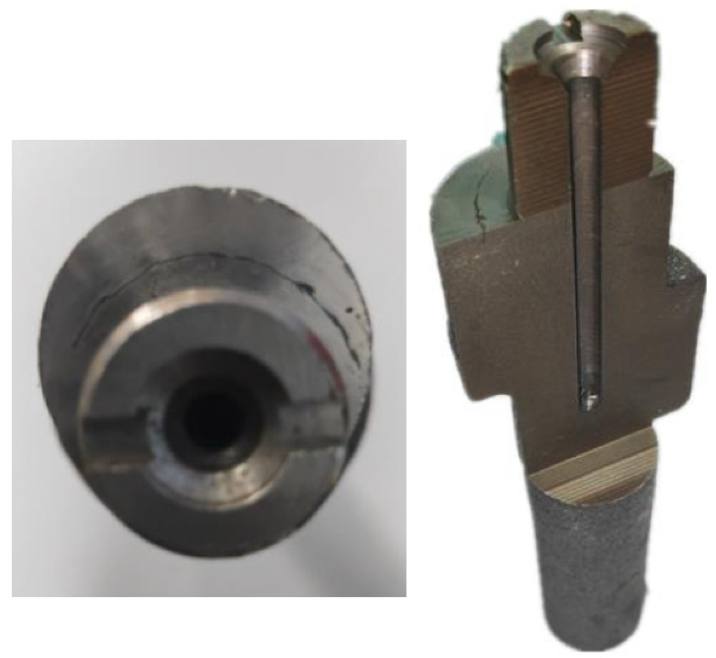
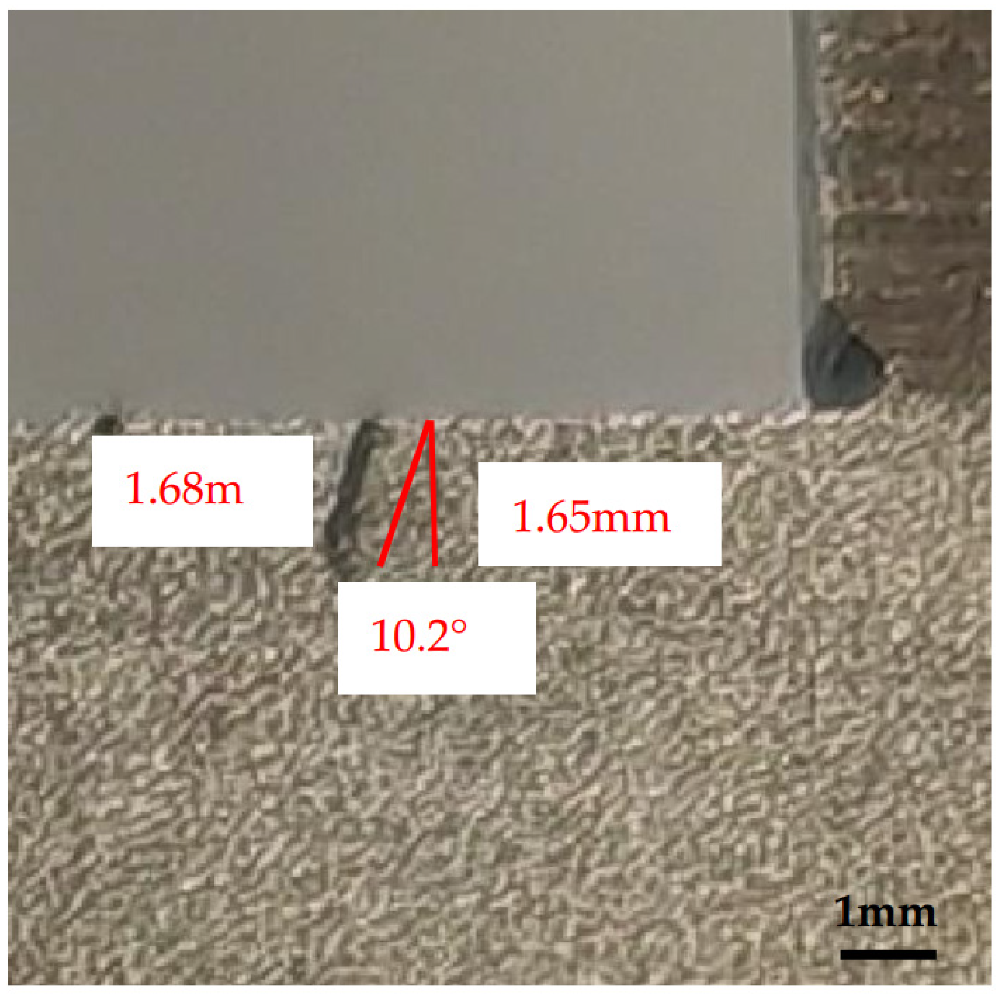
- Defects were observed on the upper end face of the first step of forgings.
- Through metallographic and simulation analysis, the defect is a forging crack.
- The method of setting the guiding angle can eliminate the forging crack defect.
Abstract

1. Introduction
2. Materials and Methods
2.1. Materials
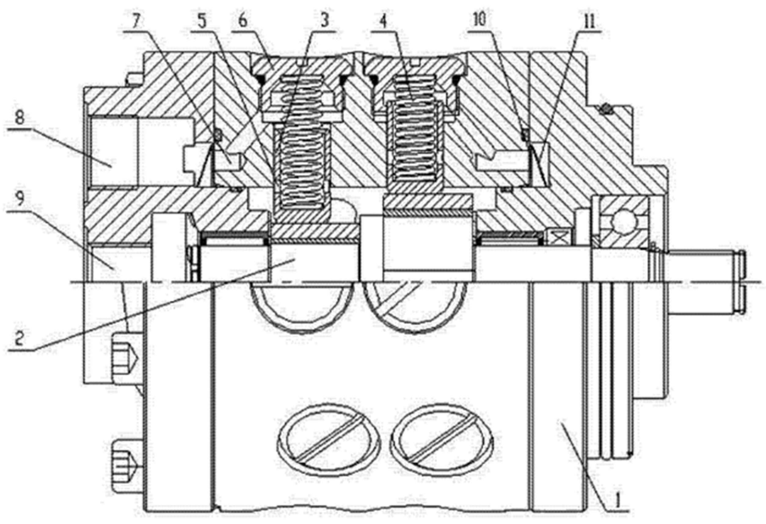
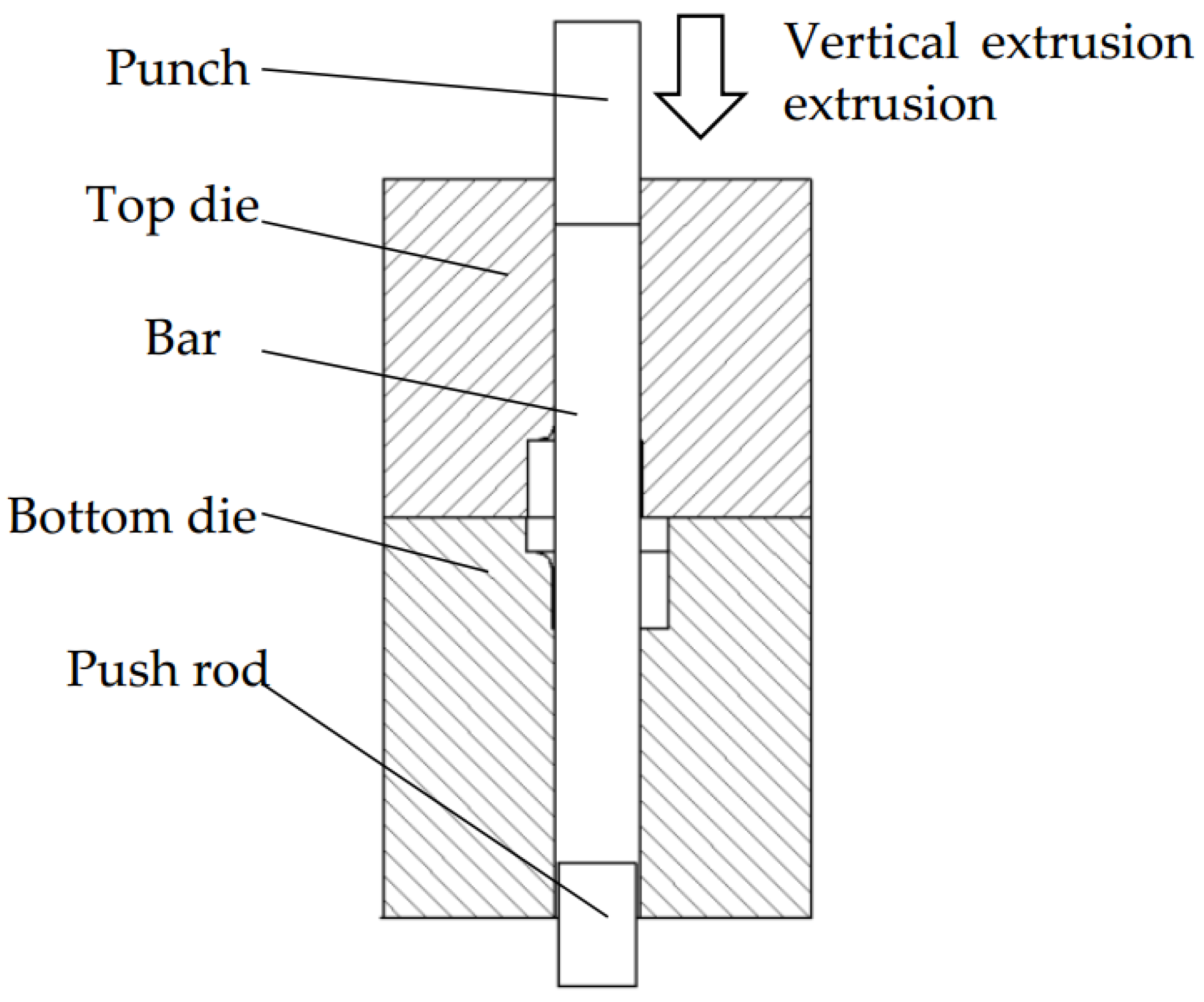
2.2. Initial Forming Process
2.3. Defect Analysis Method
3. Results and Discussion
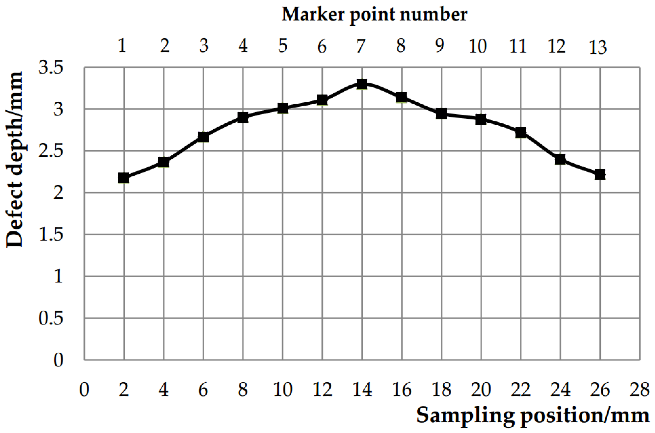
3.1. Macroscopic Morphological Analysis of Forging Defects
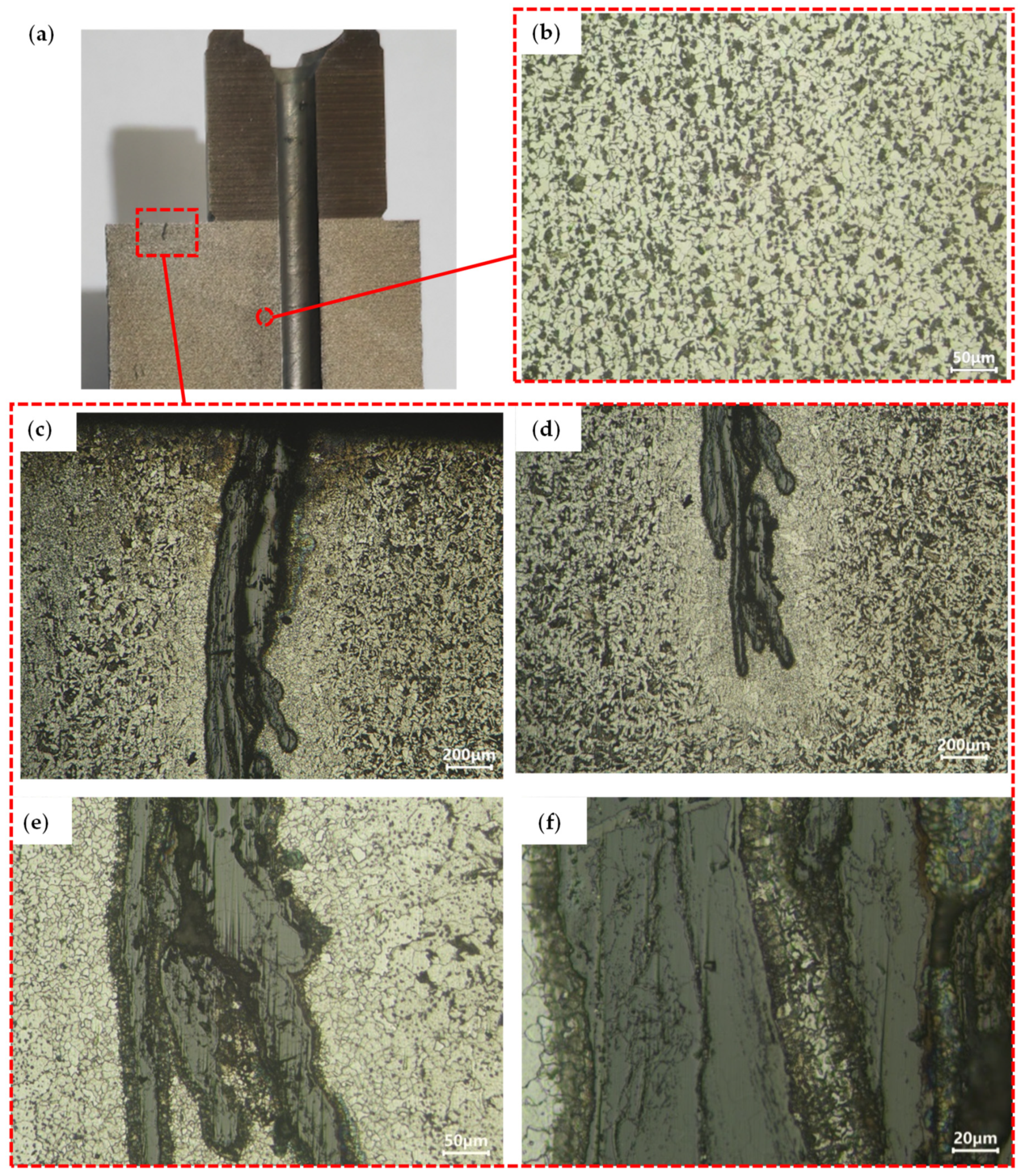
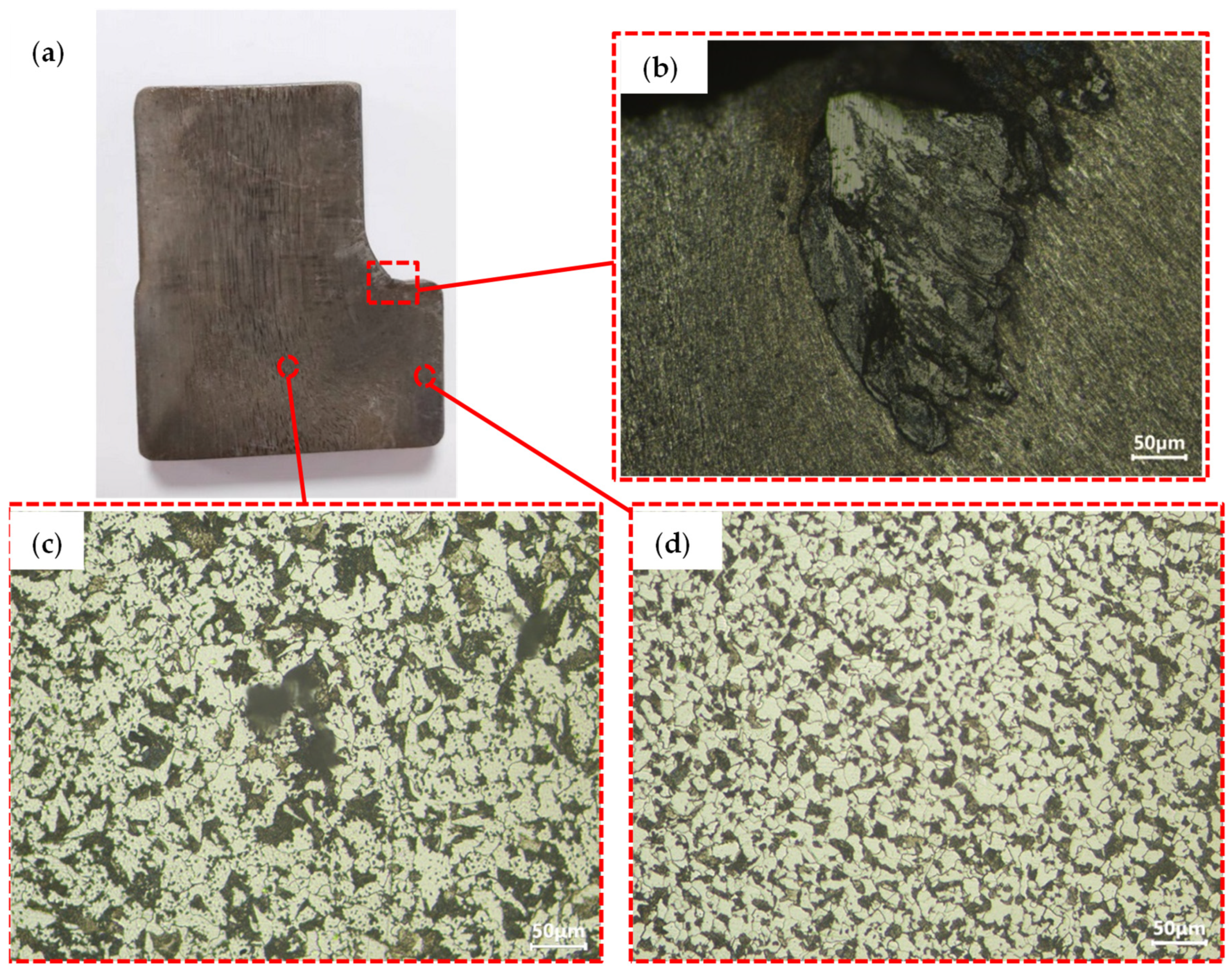
3.2. Microstructure Analysis of Normalized and Forged Forgings
3.3. Numerical Simulation Analysis of Eccentric Camshaft Forming
4. Defect Elimination Method
5. Conclusions
- (1)
- Defects in vertical upsetting extrusion camshaft forgings originate during the forging process. The subsequent normalizing process exacerbates decarburization near the defects. The defects function as stress concentration points during the normalizing process, resulting in further deepening of the defects.
- (2)
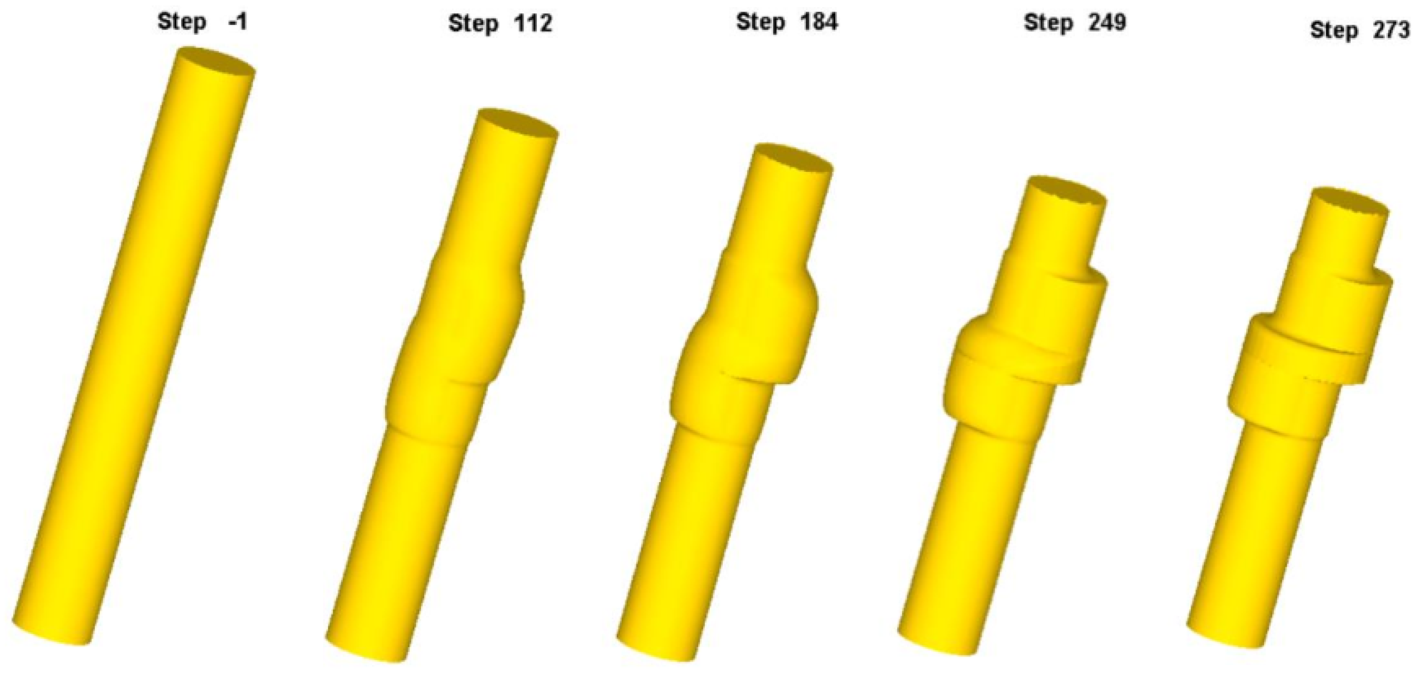
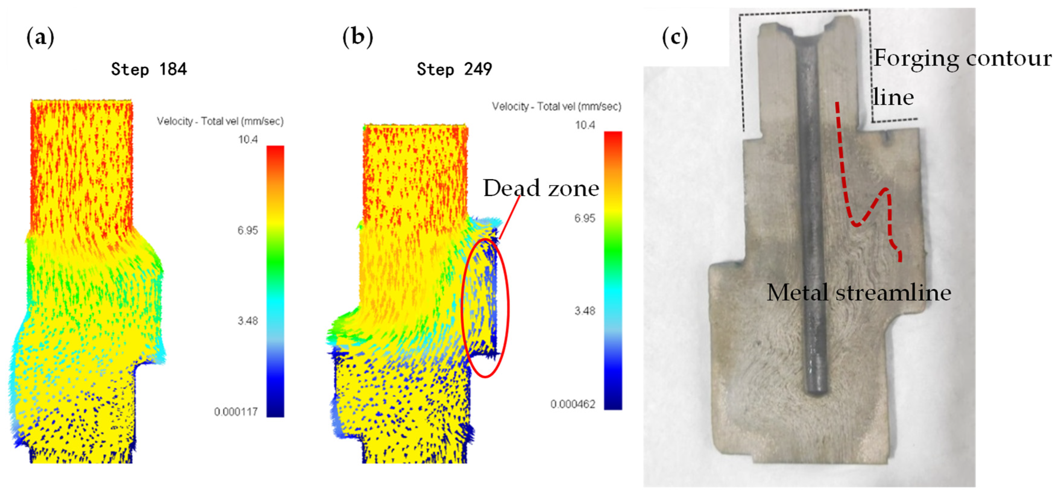
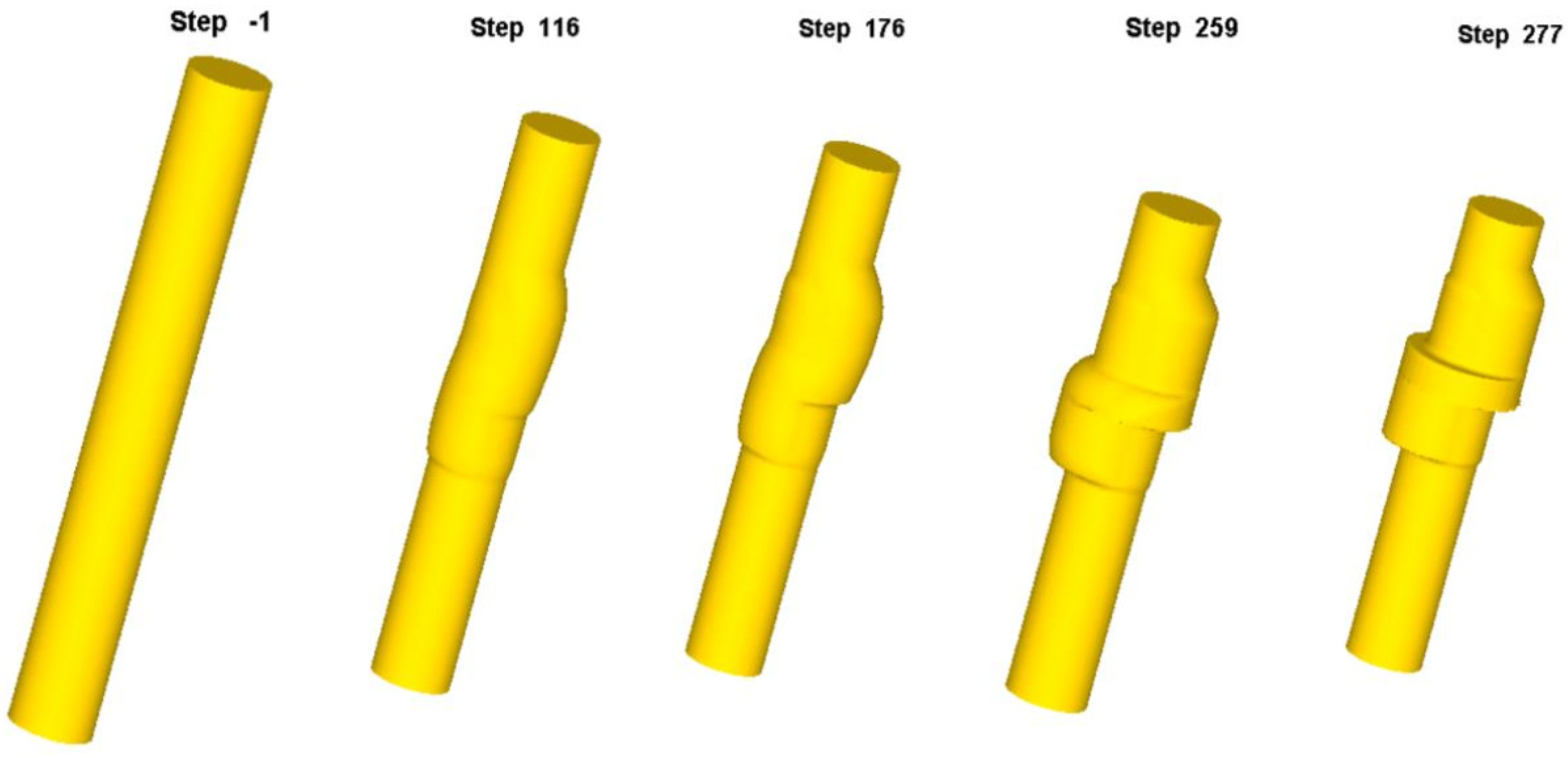
- The defect in vertical upsetting extrusion camshafts is cracking. During forming, the first step of the forging is initially filled, creating a deformation dead zone. At this stage, metal flow lines at the first step align with its contour. As metal continues to extrude into the die cavity, the inflowing metal pulls the dead zone metal downward, bending the contour-aligned flow lines into an S-shaped pattern. Cracks form when the tensile stress in the dead zone exceeds the material’s critical tensile stress.
- (3)
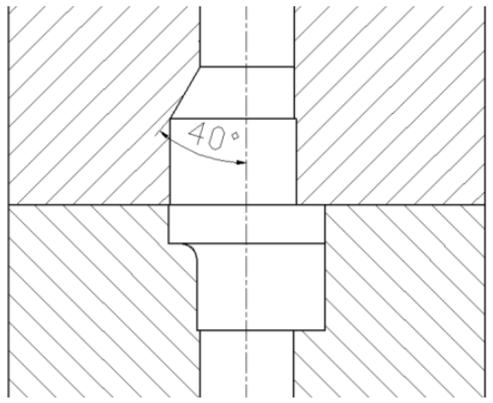
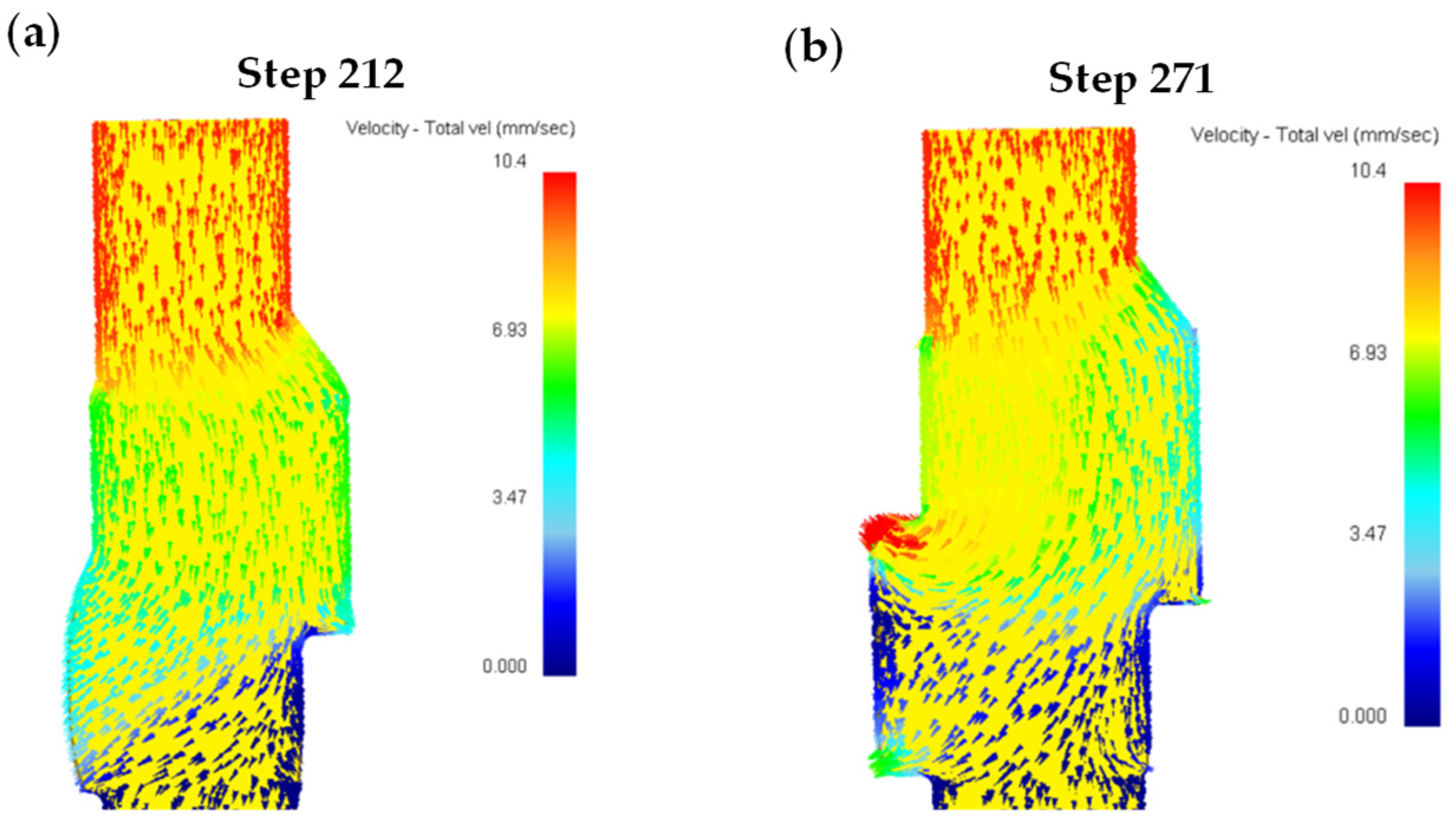
- To address crack formation, an optimized forming strategy was developed: a unidirectional upsetting extrusion method with a 40° diversion angle incorporated at the junction between the first step and the thin rod in the die cavity. Numerical simulations confirmed that no deformation dead zone formed at the first step after unidirectional extrusion of the billet into the die cavity. Post-filling of the first step, the metal in this region flowed downward uniformly, redistributing into unfilled areas of the middle flange and second step. Experimental validation of the diversion-angle-integrated unidirectional forming method demonstrated crack-free forgings, proving the effectiveness of the improved approach.
Author Contributions
Funding
Institutional Review Board Statement
Informed Consent Statement
Data Availability Statement
Conflicts of Interest
References
- Sun, Y.; He, P.; Zhang, Y.; Chen, L. Modeling and Co-Simulation of Hydraulic Power Steering System. In Proceedings of the 2011 Third International Conference on Measuring Technology and Mechatronics Automation, Shanghai, China, 6–7 January 2011; Volume 2, pp. 595–600. [Google Scholar] [CrossRef]
- Claeys, X.; Canudas-De-Wit, C.; Bechart, H. Modeling and Control of Steering Actuator for Heavy Duty Vehicles. In Proceedings of the 1999 European Control Conference (ECC), Karlsruhe, Germany, 31 August–3 September 1999; pp. 1399–1404. [Google Scholar] [CrossRef]
- Lee, B. Development of Hybrid Power Steering System for Commercial Vehicle. SAE Tech. Pap. Ser. 2019, 1, 1415. [Google Scholar] [CrossRef]
- Xia, L.; Jiang, H. An Electronically Controlled Hydraulic Power Steering System for Heavy Vehicles. Adv. Mech. Eng. 2016, 8, 1687814016679566. [Google Scholar] [CrossRef]
- European Union. Commission Implementing Regulation (EU) 2021/535. Off. J. Eur. Union 2021, L 117/1, 1–206. Available online: https://eur-lex.europa.eu/eli/reg_impl/2021/535/oj/eng (accessed on 11 December 2024).
- GB 17675-2021; Steering System of Motor Vehicles-Basic Requirements. Standards Press of China: Beijing, China, 2015.
- Raja Ramakrishnaa, B.U.; Murali, S. Design and Modelling of Emergency Power Steering System for Heavy Vehicles. Mater. Today Proc. 2020, 46, 3876–3881. [Google Scholar] [CrossRef]
- Hou, X.; Wang, X.; Wen, S.; Sun, S.; Liu, X. Analysis of Structure & Theory of Hydraulic Oil Supply System for Emergency Power Steering in Vehicle. Automob. Technol. 2009, 03, 32–35. [Google Scholar] [CrossRef]
- Shi, G.; Zhang, H.; Wang, S.; Ju, C.; Sang, D. Research on Emergency Steering Control Method of Integrated Electric-Hydraulic Steering System for Commercial Vehicle. Jixie Gongcheng Xuebao J. Mech. Eng. 2023, 59, 149–158. [Google Scholar] [CrossRef]
- Benetti, A.; Franco, G.; Malvano, M.; Moratti, S. Hydraulic Pump System of an Emergency Hydraulic Power Steering. European Patent Applications ES2621754T3, 11 January 2013. [Google Scholar]
- Xiao, C.; Yang, J.; Wang, Z. Vehicle Emergency Steering Control Method and System, Vehicle. China Patent CN114852167B, 8 August 2023. [Google Scholar]
- Chen, Z.; Zhang, J. Emergency Pump. China Patent CN03655609U, 18 June 2014. [Google Scholar]
- Jo, A.R.; Jeong, M.S.; Lee, S.K.; Moon, Y.H.; Hwang, S.K. Multi-Stage Cold Forging Process for Manufacturing a High-Strength One-Body Input Shaft. Materials 2021, 14, 532. [Google Scholar] [CrossRef]
- Saquib, A.N.; Khaleed, H.M.T.; Badruddin, I.A.; Algahtani, A.; Addas, M.F.; Abdullah, A.B.; Athani, A.; Kamangar, S.; Yunus Khan, T.M. Development of Preform for Simulation of Cold Forging Process of A V8 Engine Camshaft Free from Flash & Under-Filling. Mathematics 2019, 7, 1026. [Google Scholar] [CrossRef]
- Han, S.; Shu, X.; Chen, T.; Chang, Y.; Chen, J.; Chen, X.; Xiang, W. Study on the Progressive Forming Mechanism of Multi-Step Shafts Based on Convex-End Billet in the Cross Wedge Rolling Technology. J. Mech. Sci. Technol. 2019, 33, 6021–6035. [Google Scholar] [CrossRef]
- Tsao, T.C.; Sun, Z.; Hanson, R.D.; Babinski, A. Design, Modeling, and Motion Control of the Noncircular Turning Process for Camshaft Machining. J. Dyn. Syst. Meas. Control Trans. 2008, 130, 031005. [Google Scholar] [CrossRef]
- Weroński, W.S.; Gontarz, A.; Pater, Z. The Research of Forging Process of Eccentric Part on Three Slide Forging Press. J. Mater. Process. Technol. 2006, 177, 214–217. [Google Scholar] [CrossRef]
- Zhbankov, I.G.; Perig, A.V.; Aliieva, L.I. New Schemes of Forging Plates, Shafts, and Discs. Int. J. Adv. Manuf. Technol. 2016, 82, 287–301. [Google Scholar] [CrossRef]
- Gao, P.F.; Fei, M.Y.; Yan, X.G.; Wang, S.B.; Li, Y.K.; Xing, L.; Wei, K.; Zhan, M.; Zhou, Z.T.; Keyim, Z. Prediction of the Folding Defect in Die Forging: A Versatile Approach for Three Typical Types of Folding Defects. J. Manuf. Process. 2019, 39, 181–191. [Google Scholar] [CrossRef]
- Ge, X.; Yu, Y.; Yu, H.; Wang, G. Study on Folding Defect Elimination Method of Track Link Forging Based on Preforming Design. Int. J. Precis. Eng. Manuf. 2023, 24, 61–71. [Google Scholar] [CrossRef]
- Jiang, B.; Dong, Z.Q.; Yang, Z.; Zhou, L.Y.; Liu, Y.Z.; Wang, Y.N. Analysis of the Formation of Surface Crack on Crankshaft After Die Forging. Trans. Indian Inst. Met. 2015, 68, 553–559. [Google Scholar] [CrossRef]
- Bahrami, A.; Khouzani, M.K.; Mokhtari, S.A.; Zareh, S.; Mehr, M.Y. Root Cause Analysis of Surface Cracks in Heavy Steel Plates During the Hot Rolling Process. Metals 2019, 9, 801. [Google Scholar] [CrossRef]
- GB/T3077-2015; Alloy Structural Steels. Standards Press of China: Beijing, China, 2015.
- Gündüz, S.; Çapar, A. Influence of Forging and Cooling Rate on Microstructure and Properties of Medium Carbon Microalloy Forging Steel. J. Mater. Sci. 2006, 41, 561–564. [Google Scholar] [CrossRef]
- Nürnberger, F.; Grydin, O.; Schaper, M.; Bach, F.W.; Koczurkiewicz, B.; Milenin, A. Microstructure Transformations in Tempering Steels during Continuous Cooling from Hot Forging Temperatures. Steel Res. Int. 2010, 81, 224–233. [Google Scholar] [CrossRef]
- Wang, W.; Liang, C.; Zeng, J.; Zhou, Y.; Chen, B.; He, H. Mechanism of Tempered Sorbite Formation and Related Enhanced Mechanical Properties for a Typical High Carbon Steel Billet Under Strong Cooling Intensity. Metall. Mater. Trans. B Process Metall. Mater. Process. Sci. 2021, 52, 4061–4069. [Google Scholar] [CrossRef]
- Li, S.; Wang, Y.; Li, Z.; Liu, X.; Zhao, S. Study on the Semi-Solid Thixotropic Forging Forming Process for the Low-Carbon Steel Claw Pole. Materials 2023, 16, 4790. [Google Scholar] [CrossRef]
- Wang, T.; Zhang, Y.; Sun, H.; Wang, Z.; Liu, H. Research on Deformation Coordination of Composite Metal Gears in the Process of Cold Extrusion. J. Phys. Conf. Ser. 2022, 2338, 012048. [Google Scholar] [CrossRef]


| Element | C | Si | Mn | P | S | Cr | Cu | Ti |
|---|---|---|---|---|---|---|---|---|
| Results | 0.19 | 0.23 | 0.96 | 0.01 | 0.01 | 1.05 | 0.007 | 0.08 |
| Standard Value (GB/T3077-2015) | 0.17~0.23 | 0.17~0.37 | 0.80~1.10 | ≤0.035 | ≤0.035 | 1.00~1.30 | ≤0.035 | 0.04~0.10 |
Disclaimer/Publisher’s Note: The statements, opinions and data contained in all publications are solely those of the individual author(s) and contributor(s) and not of MDPI and/or the editor(s). MDPI and/or the editor(s) disclaim responsibility for any injury to people or property resulting from any ideas, methods, instructions or products referred to in the content. |
© 2025 by the authors. Licensee MDPI, Basel, Switzerland. This article is an open access article distributed under the terms and conditions of the Creative Commons Attribution (CC BY) license (https://creativecommons.org/licenses/by/4.0/).
Share and Cite
Wang, T.; Sun, H.; Hu, N.; Liu, D.; Wang, Z.; Liu, G.; Zhang, C.; Liu, H. Defect Analysis and Improvement Method of Eccentric Camshaft Forging by Vertical Upsetting Extrusion Forming. Materials 2025, 18, 1468. https://doi.org/10.3390/ma18071468
Wang T, Sun H, Hu N, Liu D, Wang Z, Liu G, Zhang C, Liu H. Defect Analysis and Improvement Method of Eccentric Camshaft Forging by Vertical Upsetting Extrusion Forming. Materials. 2025; 18(7):1468. https://doi.org/10.3390/ma18071468
Chicago/Turabian StyleWang, Tao, Hongxing Sun, Nan Hu, Dan Liu, Zhen Wang, Guanghui Liu, Chao Zhang, and Hua Liu. 2025. "Defect Analysis and Improvement Method of Eccentric Camshaft Forging by Vertical Upsetting Extrusion Forming" Materials 18, no. 7: 1468. https://doi.org/10.3390/ma18071468
APA StyleWang, T., Sun, H., Hu, N., Liu, D., Wang, Z., Liu, G., Zhang, C., & Liu, H. (2025). Defect Analysis and Improvement Method of Eccentric Camshaft Forging by Vertical Upsetting Extrusion Forming. Materials, 18(7), 1468. https://doi.org/10.3390/ma18071468