
High-Temperature Strain Gauge Measurement Techniques for Temperatures Above 800 °C: A Review


Abstract
:1. Introduction
2. Application Fields
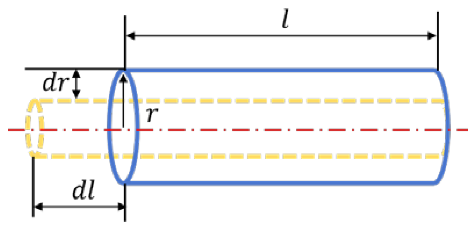
3. Measurement Basics
4. Research Status
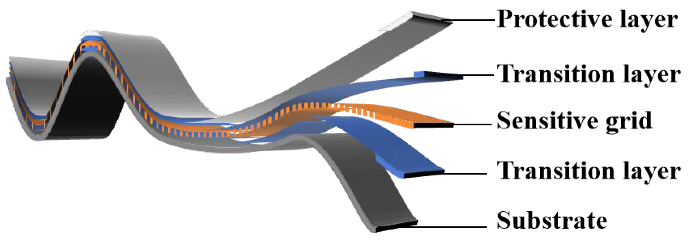
4.1. Sensitive Grid
4.1.1. Material
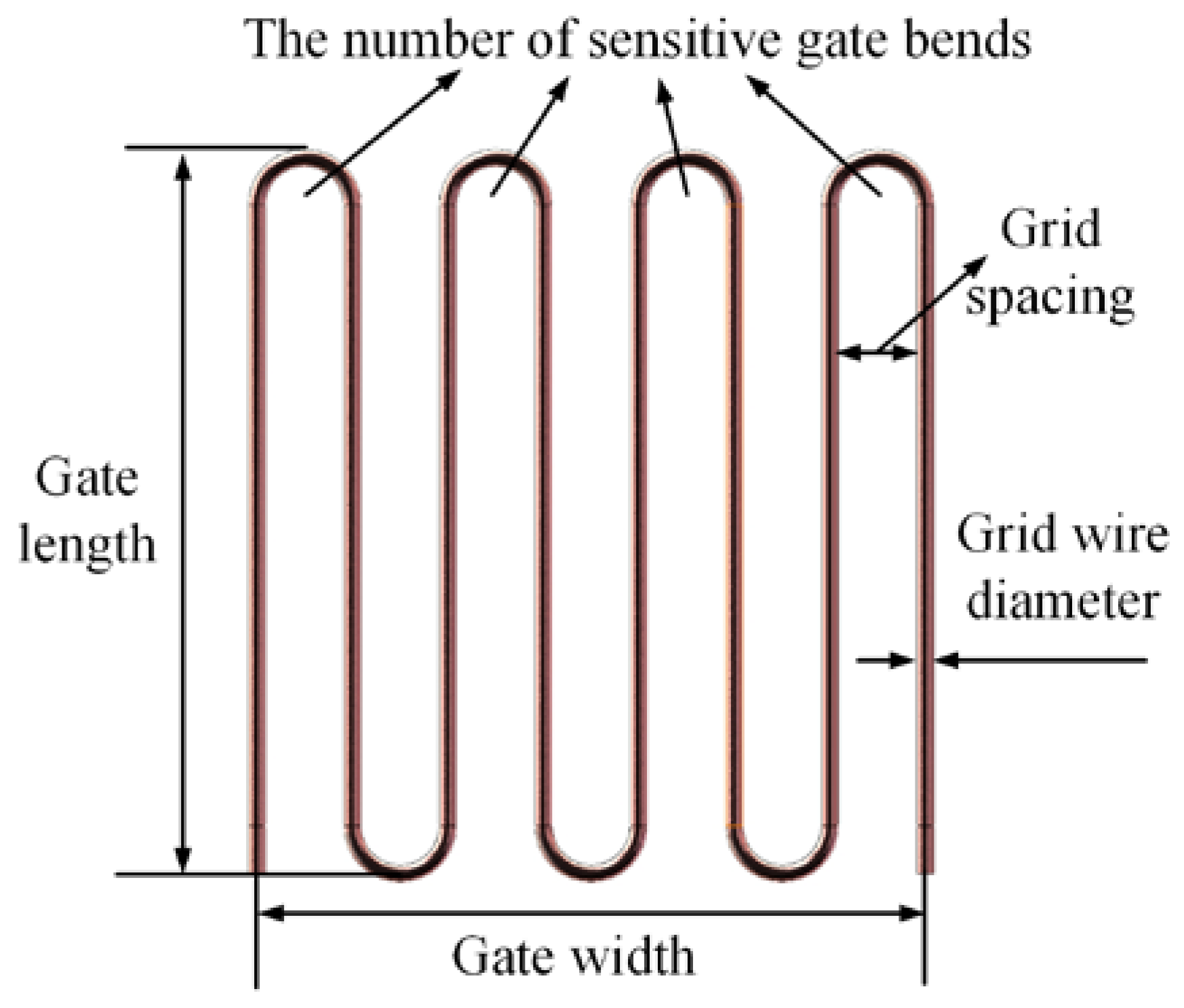
4.1.2. Structure
- ①
- Size: gate length () × gate width ();
- ②
- Grid wire diameter ();
- ③
- Grid spacing ();
- ④
- the number of sensitive gate bends ().
4.2. Transition Layer
4.3. Protective Layer
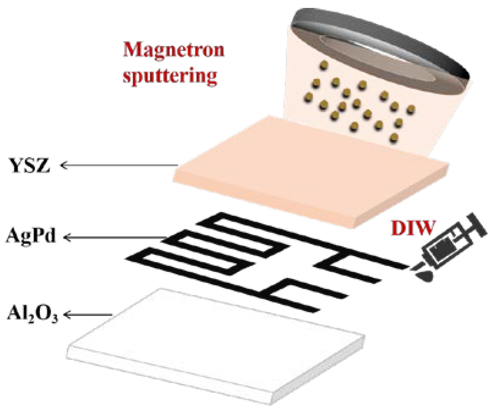
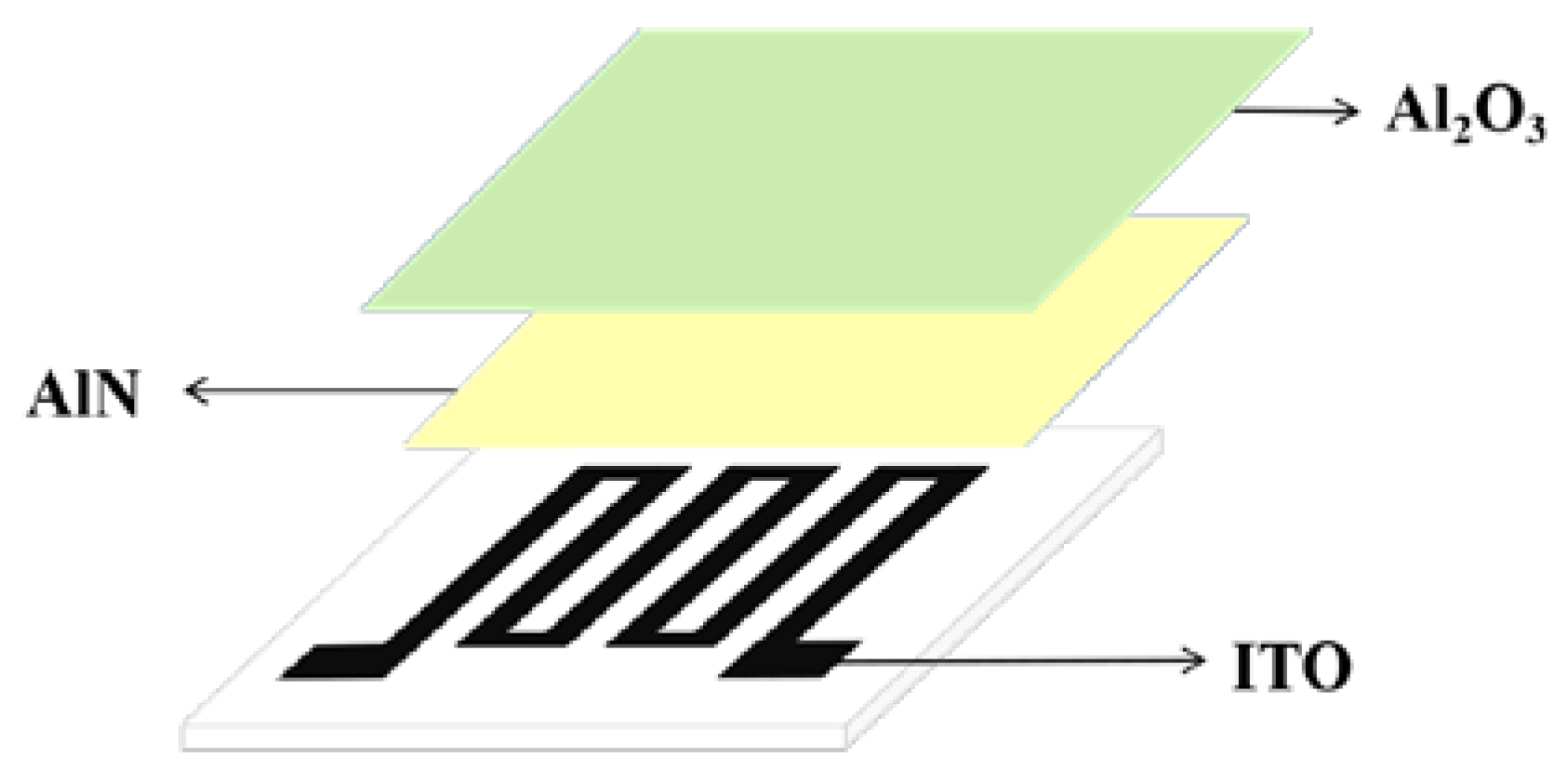
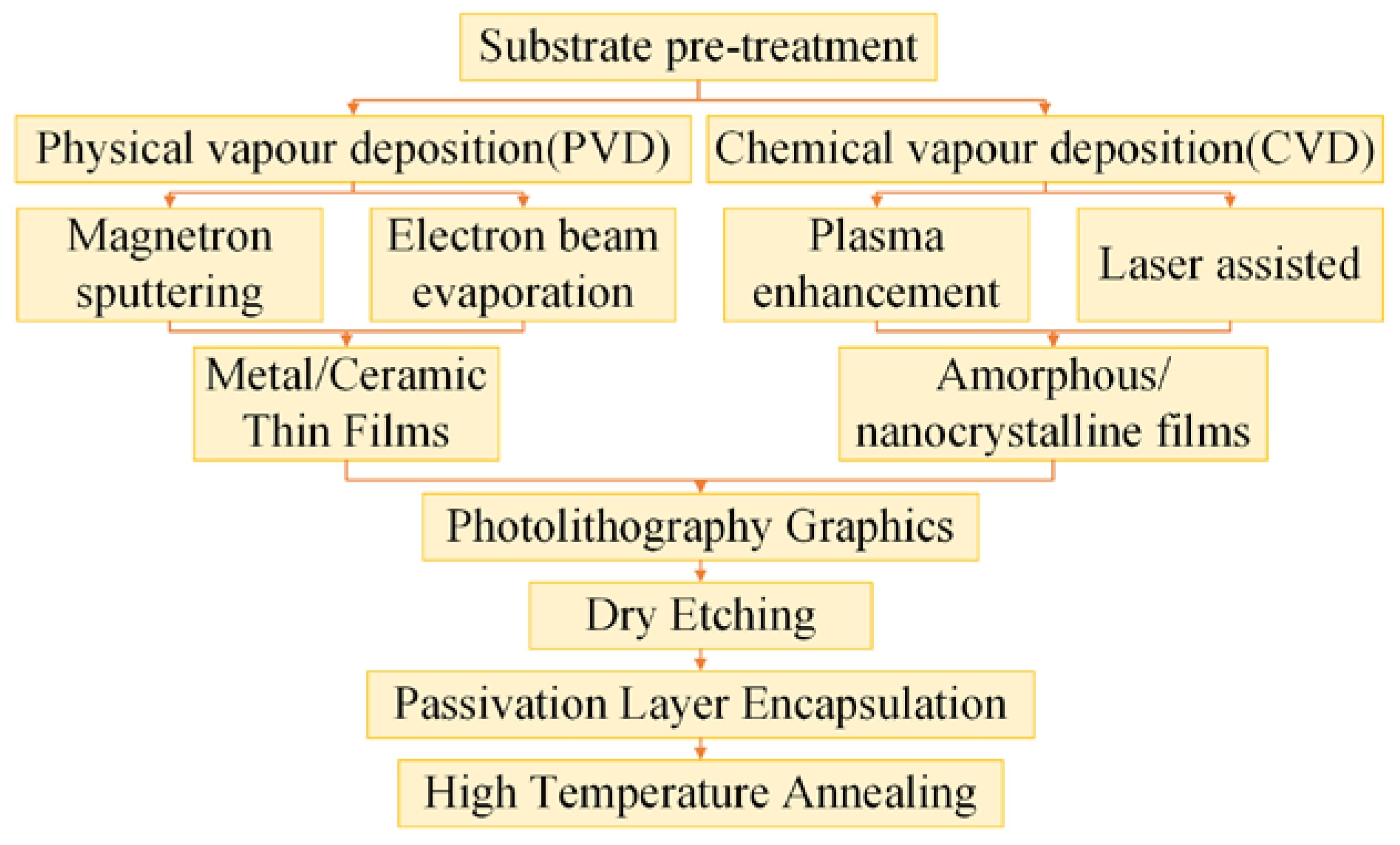
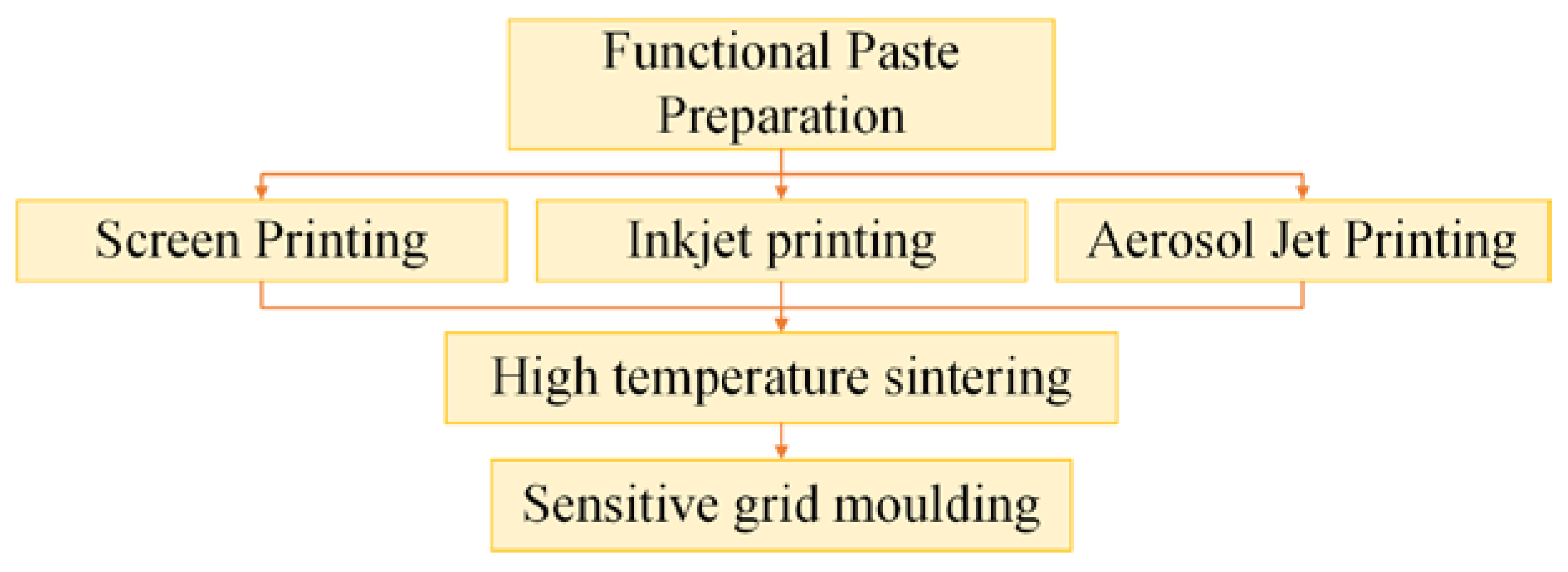
4.4. Preparation Process
4.5. Future Outlook
5. Conclusions
Author Contributions
Funding
Data Availability Statement
Conflicts of Interest
References
- Yin, F.Y.; Wang, W.R.; Yan, X.Q. High Temperature/Low Temperature Resistance Strain Gauge and Its Application; National Defense Industry Press: Beijing, China, 2014; p. 2. [Google Scholar]
- Chen, C.Y.; Zhou, S.W.; Zhou, Z.Z.; Jiang, S.W. Simulation Study on the Strain Transfer Process of High Temperature Thin Film Strain Gauges. Aeronaut. Sci. Technol. 2024, 35, 76–83. [Google Scholar]
- Wang, W.R.; Wen, X.Q.; Hu, T.; Zhang, J.M. Thermal Output Coupling Characteristics of High-Temperature Strain Gauges. Chin. J. Eng. 2018, 40, 1131–1137. [Google Scholar]
- Zou, X.F.; Guo, D.W.; Pan, K.; Qu, C.; Tao, Y.Q.; Zhang, X.D. Test Technique for Multi-Load Combined Strength of Hypersonic Vehicle Structure under Complex Loading Environment. Acta Aeronau 2018, 39, 222326. [Google Scholar]
- Lu, Z.F.; Wang, J.; Pang, S.L. High Temperature Strain Testing Technology for Components of Nuclear Power Equipment. Acta Aeronau 2024, 3, 43–45. [Google Scholar]
- Wang, S.J.; He, J.J.; Li, W.P.; Gong, Z.H.; Zhou, L.B.; Yang, J.G.; Cai, Y.H.; Du, Y.X. Microstructure analysis and cracking mechanism of aero-engine hot-end component K4169 superalloy based on in-situ EBSD test. J. Alloys Compd. 2023, 960, 170781. [Google Scholar] [CrossRef]
- Xu, L.D.; Li, L.L.; Tang, L.T.; Zeng, Y.H.; Chen, G.C.; Shao, C.H.; Wu, C.; He, G.H.; Chen, Q.N.; Fang, Q.N.; et al. Rapid Printing of High-Temperature Polymer-Derived Ceramic Composite Thin-Film Thermistor with Laser Pyrolysis. ACS Appl. Mater. Interfaces 2023, 15, 9996–10005. [Google Scholar] [CrossRef]
- Dutta, A.; Tangamani, I.; Shanware, V.M.; Rao, K.S. Experiments and analytical studies related to blowdown and containment thermal hydraulics on CSF. Nucl. Eng. Des. 2015, 294, 233–241. [Google Scholar] [CrossRef]
- Phero, T.L.; Novich, K.A.; Johnson, B.C.; McMurtrey, M.D.; Estrada, D.; Jaques, B.J. Additively manufactured strain sensors for in-pile applications. Sens. Actuators A Phys. 2022, 344, 113691. [Google Scholar] [CrossRef]
- Ham, S.; Kim, K.; Kim, J.; Min, N.K.; Choi, W.S.; Park, C.W. Design, fabrication, and characterization of piezoresisitve strain gage-based pressure sensors for mechatronic systems. In Proceedings of the 2015 IEEE International Workshop of Electronics, Control, Measurement, Signals and their Application to Mechatronics (ECMSM) 2015, Liberec, Czech Republic, 22–24 June 2015; pp. 1–5. [Google Scholar]
- Lall, P.; Thomas, T.; Suhling, J. Prognostication of Damage in Automotive Underhood Electronics Subjected to Temperature and Vibration. In Proceedings of the 2018 IEEE 68th Electronic Components and Technology Conference (ECTC) 2018, San Diego, CA, USA, 29 May–1 June 2018; pp. 1330–1341. [Google Scholar]
- Jia, J.H.; Hu, X.Y.; Wang, N.; Tu, S.T. Test verification of an extensometer for deformation measurement of high temperature straight pipes. Meas. J. Int. Meas. Confed. 2012, 45, 1933–1936. [Google Scholar] [CrossRef]
- Hu, X.Y.; Jia, J.H.; Wang, N.; Xia, X.M.; Wang, Z.D.; Tu, S.T. Design and test of an extensometer for strain monitoring of high temperature pipelines. J. Press. Vessel Technol.-Trans. Asme 2012, 134, 044501. [Google Scholar] [CrossRef]
- Zhang, H.C.; Jia, J.H.; Wang, N.; Hu, X.Y.; Tu, S.T.; Zhou, S.P.; Wang, Z.D. Development of on-line monitoring systems for high temperature components in power plants. Sensors 2013, 13, 15504–15512. [Google Scholar] [CrossRef] [PubMed]
- Chen, C.Y. Research on Design and Preparation of High Temperature Thin Film Strain Gauges. Master’s Thesis, School of Integrated Circuit Science and Engineering, Chengdu, China, 2024; pp. 9–10. [Google Scholar]
- Wang, W.R.; Zhang, J.M.; Nie, S. Simulation and Experiment on Influence Factor of Contact High Temperature Strain Measurement Accuracy. J. Solid Rocket Technol. 2015, 38, 439–444. [Google Scholar]
- Wan, J.G.; Wu, H.J.; Yang, L.J.; Niu, H.D.; Lu, S.P.; Hao, Y.J. Progress on Research and Application of Strain Alloys Resistant to High Temperature. Precious Met. 2023, 44, 74–84. [Google Scholar]
- Yin, F.Y. Sixty Years of Electric Resistance Strain Gage Technique (2): Development of Grid Sensing Materials for Electric Resistance Strain Gage (II). Sens. World 1998, 10, 9–13. [Google Scholar]
- Wang, W.R.; Zhang, J.M. The Invention Relates to a Temporary Frame Wire Grid Type High Temperature Strain Gauge and Its Manufacture and Application Method. Patent No. ZL201810726352.3, 21 December 2018. [Google Scholar]
- Xu, Y.Z.; Lei, X.B.; Wen, M.; Hu, C.X.; Zhao, B. High Temperature Load Measurement for Nozzle Component of a Certain Aero-Engine. J. Mech. Strength 2019, 41, 696–701. [Google Scholar]
- Zhang, J.M.; Wang, W.R.; Wang, G. Strength Analysis of Turbine Blade Based on Contact High Temperature Strain Test Experiment. Gas Turbine Exp. Res. 2020, 33, 25–29. [Google Scholar]
- Hulse, C.O.; Bailey, R.S.; Grant, H.P. High Temperature Static Strain Gage Development; NASA CR189044; NASA: Washington, DC, USA, 1990. [Google Scholar]
- Liu, H.; Jiang, S.W.; Jiang, H.C.; Zhao, X. Fabrication of PdCr Thin Film Strain Gauge and Investigation on Its Sensitive Properties at High Temperature. Chin. J. Sens. Actuators 2017, 30, 348–352. [Google Scholar]
- Liu, H.; Mao, X.L.; Yang, Z.B.; Cui, J.T.; Jiang, S.W.; Zhang, W.L. High Temperature Static and Dynamic Strain Response of PdCr Thin Film Strain Gauge Prepared on Ni-Based Superalloy. Sens. Actuators A Phys. 2019, 298, 111571. [Google Scholar]
- Guo, J.X.; Tong, L.Z.; Chen, L. Platinum Alloy Strain Gauge Materials Noble Metal Alloys for Static Measurement at 900 °C. Platin. Met. Rev. 1997, 41, 23–32. [Google Scholar]
- Zhang, T.L. Development of PtRh6 High Temperature Film Strain Gauge for Turbine Stator Blade Surface; Dalian Jiaotong University: Dalian, China, 2021; pp. 71–72. [Google Scholar]
- Liang, J.J. Research of Integrated Temperature-Strain Thin Film Sensor; School of Integrated Circuit Science and Engineering: Chengdu, China, 2023; pp. 56–57. [Google Scholar]
- Chen, Z.; Zhang, J.Y.; Zhao, X.H. Effect of High Temperature Annealing on the Properties of PtW Thin Film Strain Gauge on Alloy Substrate. Electron. Compon. Mater. 2024, 43, 538–543. [Google Scholar]
- Yang, S.Y. Study on Piezoresistive Stability and Temperature Effect of High Temperature Thin Film Strain Gages; Shanghai Jiao Tong University: Shanghai, China, 2020; pp. 9–10. [Google Scholar]
- Chung, G.S. Characteristics of Tantalum Nitride Thin Film Strain Gauges for Harsh Environments. Sens. Actuators A Phys. 2007, 135, 355–359. [Google Scholar] [CrossRef]
- Wu, C.; Pan, X.C.; Lin, F.; Cui, Z.; He, Y.; Chen, G.; Zeng, Y.; Liu, X.; Chen, Q.; Sun, D.; et al. TiB2/SiCN Thin-Film Strain Gauges Fabricated by Direct Writing for High-Temperature Application. IEEE Sens. J. 2022, 22, 11517–11525. [Google Scholar] [CrossRef]
- Xu, L.D.; Zhou, X.; Zhao, F.X.; Fu, Y.Z.; Tang, L.T.; Zeng, Y.J.; Chen, G.H.; Wu, C.; Wang, L.Y.; Chen, Q.N. Rapid Laser Fabrication of Indium Tin Oxide and Polymer-Derived Ceramic Composite Thin Films for High-Temperature Sensors. J. Colloid Interface Sci. 2024, 658, 913–922. [Google Scholar] [PubMed]
- Yang, S.Y.; Zhang, C.C.; Yang, Z.Q.; Wang, H.; Zhao, X.L.; Ding, G.F. In-Situ Self-Compensated PT-ITO Thin Film Strain Gage with a Nanolaminated Structure. In Proceedings of the 20th International Conference on Solid-State Sensors, Actuators and Microsystems & Eurosensors, Berlin, Germany, 23–27 June 2019; pp. 2005–2008. [Google Scholar]
- Gregory, O.; Chen, X.M. A Low TCR Nanocomposite Strain Gage for High Temperature Aerospace Applications. In Proceedings of the 2007 IEEE Sensors, Atlanta, GA, USA, 28–31 October 2007; pp. 624–627. [Google Scholar]
- Zarfl, C.; Schwab, S.; Schmid, P.; Hutter, H.; Schmid, U. Influence of the sputter gas composition on the electromechanical properties and on the stability of TiAlNxO1-x thin films. Sens. Actuators A Phys. 2017, 267, 552–559. [Google Scholar] [CrossRef]
- Rahman, M.T.; Moser, R.; Zbib, H.M.; Ramana, C.V.; Panat, R. 3D printed high performance strain sensors for high temperature applications. J. Appl. Phys. 2018, 123, 024501. [Google Scholar] [CrossRef]
- Schmid, P.; Triendl, F.; Zarfl, C.; Schwarz, S.; Artner, W.; Schneider, M.; Schmid, U. Electro-mechanical properties of multilayered aluminum nitride and platinum thin films at high temperatures. Sens. Actuators A Phys. 2019, 293, 128–135. [Google Scholar] [CrossRef]
- Jan, C.; Jindrich, R.; Filip, R. Comparison of Various Means of Attachment of High Temperature Strain Gauge. Appl. Mech. Mater. 2015, 732, 199–202. [Google Scholar]
- Wrbanek, J.D.; Fralik, G.C. Thin Film Physical Sensor Instrumentation Research and Development at NASA Glenn Research Center; NASA/TM 2006, 214395; NASA: Washington, DC, USA, 2006. [Google Scholar]
- Yu, H.; Shu, A.Q.; Ding, K.Q. Research on the Influence of the Size of Strain Gauge Sensitive Grid Wire on Measurement Accuracy. China Instrum. 2021, 4, 71–75. [Google Scholar]
- Ai, Y.Y.; Liu, M.; Zhang, F.L.; Zhang, X.; Zhao, Y.Z. Research on the Structural Optimization Method to Improve the Service Life and Accuracy of High Temperature Strain Gauge. Chin. J. Sci. Instrum. 2022, 43, 151–161. [Google Scholar]
- Zhang, F.L.; Zhang, X.; Ai, Y.T.; Zhao, Y.Z. Sensitive Grid Structure Optimization of High Temperature Strain Gauge Based on Response Surface Methodology. Chin. J. Sci. Instrum. 2023, 44, 144–155. [Google Scholar]
- Zhang, C.C.; Kang, Z.P.; Zhao, N.; Peng, L.; Yan, B. A Bilayer Thin-Film Strain Gauge with Temperature Self-Compensation. IEEE Sens. J. 2023, 23, 5601–5608. [Google Scholar] [CrossRef]
- Wu, C.; Lin, F.; Fu, Y.Z.; Zeng, Y.J.; Chen, G.C.; Xu, L.D.; Pan, X.C.; Chen, Q.N.; Sun, D.H.; Hai, Z.Y. Multilayer Co-Sintered Pt Thin-Film Strain Gauge for High-Temperature Applications. Surf. Coat. Technol. 2023, 459, 0257–8972. [Google Scholar] [CrossRef]
- Zhao, F.X.; Chen, G.C.; Zeng, Y.J.; Wu, C.; Pan, X.C.; Xu, L.D. Three-Dimensional Printing of Platinum-Rhodium High-Temperature Thick Film Strain Gauge. IEEE Sens. J. 2023, 23, 22256–22262. [Google Scholar] [CrossRef]
- Zhao, Y.C.; Li, Y.H.; Wu, Y.J.; Ding, G.F.; Zhang, C.C. High-Temperature PdCr Thin-Film Strain Gauge with High Gauge Factor Based on Cavity Structure. IEEE Sens. J. 2024, 24, 9573–9584. [Google Scholar] [CrossRef]
- Wu, C.; Chen, G.C.; Zhao, F.X.; Lin, F.; Zeng, Y.J.; Fu, Y.Z.; Zhang, Y.S.; Xu, L.D.; Chen, Q.N.; Tang, R.; et al. Innovative Coaxial High-Temperature Thin-Film Sensor with Core-Shell Structure Surpassing Traditional Multilayer Films. Rare Met. 2024, 43, 3854–3867. [Google Scholar] [CrossRef]
- Yang, X.D. Fabrication of PdCr High Temperature Thin Film Strain Gauges. Ph.D. Dissertation, Shanghai Jiao Tong University, Shanghai, China, 2016; pp. 51–52. [Google Scholar]
- Liu, H.; Jiang, S.W.; Zhao, X.H.; Jiang, H.C.; Zhang, W.L. YSZ/Al2O3 Multilayered Film as Insulating Layer for High Temperature Thin Film Strain Gauge Prepared on Ni-Based Superalloy. Sens. Actuators A Phys. 2018, 279, 272–277. [Google Scholar]
- Chen, L. Preparation of Key Structure of Ultrahigh Temperature Thin Film Strain Sensor. Ph.D. Dissertation, Dalian University of Technology, Dalian, China, 2019; pp. 35–38. [Google Scholar]
- Peng, X.L. The Preparation and Properties Study of High Temperature Thin Film Strain Gauge Deposited on Al2O3/CeO2 Composite Insulating Layer. Ph.D. Dissertation, Dalian University of Technology, Dalian, China, 2019; pp. 35–38. [Google Scholar]
- Liu, H.; Mao, X.L.; Cui, J.T.; Jiang, S.W.; Zhang, W.L. Influence of a Heterolayered Al2O3–ZrO2/Al2O3 Ceramic Protective Overcoat on the High Temperature Performance of PdCr Thin Film Strain Gauges. Ceram. Int. 2019, 45, 16489–16495. [Google Scholar] [CrossRef]
- Zhao, F.X.; Chen, G.C.; Shao, C.H.; Wu, W.J.; Fu, Y.Z.; Shi, Y.X.; Xu, L.D.; Wang, C.Y.; He, G.H.; Chen, Q.N.; et al. Combining 3-D Printing and Magnetron Sputtering Technique for Fabricating High-Temperature AgPd Thick Film Strain Gauge. IEEE Sens. J. 2023, 23, 28541–28548. [Google Scholar] [CrossRef]
- Zeng, Y.J.; Chen, G.C.; Zhao, F.X.; Xu, L.D.; Fu, Y.Z.; Wu, C.; Shao, C.H.; He, G.H.; Chen, Q.N.; Zhao, Y. All-Three-Dimensionally-Printed AgPd Thick-Film Strain Gauge with a Glass-Ceramic Protective Layer for High-Temperature Applications. ACS Appl. Mater. Interfaces 2023, 15, 48395–48405. [Google Scholar] [CrossRef]
- Li, S.L.; Zhang, L.; Xie, H.; Xue, Y.; Hao, Z.Y.; Dong, H.L. Effect of AlN/Al2O3 Thin-Film Protective Layer on the High-Temperature Performance of ITO Thin-Film Strain Gauge. IEEE Sens. J. 2023, 23, 11490–11497. [Google Scholar] [CrossRef]
- Sun, L.Z.; Yuan, G.W.; Gao, L.B.; Yang, J.; Chhowalla, M.; Gharahcheshmeh, M.H.; Gleason, K.K.; Choi, Y.S.; Hong, B.H.; Liu, Z.F. Chemical vapour deposition. Nat. Rev. Methods Primers 2021, 1, 5. [Google Scholar]
- Pan, X.C.; Lin, F.; Wu, C.; Zeng, Y.J.; Chen, G.C.; Chen, Q.N.; Sun, D.H.; Hai, Z.Y. Additive-Manufactured Platinum Thin-Film Strain Gauges for Structural Microstrain Testing at Elevated Temperatures. Micromachines 2022, 13, 1472. [Google Scholar] [PubMed]
- Xu, L.D.; Zhao, F.X.; Zhou, X.; Wang, Y.S.; Shen, T.T.; Liu, J.; Wang, H.D.; Guo, Y.; Zhou, X.G.; Wu, C.; et al. High-temperature thin-film strain sensors with low temperature coefficient of resistance and high sensitivity via direct ink writing. Nanotechnol. Precis. Eng. 2024, 8, 013001. [Google Scholar]
- Agarwala, S.; Goh, G.L.; Yeong, W.Y. Aerosol Jet Printed Strain Sensor: Simulation Studies Analyzing the Effect of Dimension and Design on Performance (September 2018). IEEE Access 2018, 6, 63080–63086. [Google Scholar]
- Fang, H.Y.; Luo, J.; Wang, D.K.; Yang, J.H.; Zeng, M.; Zou, Y.L.; Hu, N.T.; Yang, Z. Infrared Temperature Measurement Calibration and Temperature Field Reconstruction of Aero-Engine Blade Surface. Infrared Technol. 2024, 46, 940–946. [Google Scholar]
- Prakash, J.; Pivin, J.C.; Swart, H.C. Noble metal nanoparticles embedding into polymeric materials: From fundamentals to applications. Adv. Colloid Interface Sci. 2015, 226, 187–202. [Google Scholar]
- Vishal, C.V.C.; Kanala, R.K.; Raju, C.S.K.; Madathil, P.K.; Saha, P.; Rao, B.R.; Sriganesh, G.; Ramesh, K. Sub-micron sized metal oxides based organic thermic fluids with enhanced thermo-physical properties. Appl. Therm. Eng. 2019, 163, 114337. [Google Scholar]
- Dong, C.C.; Zhang, C.B.; He, G.N.; Li, D.H.; Zhang, Z.W.; Cong, J.D.; Meng, Z.M.; Asim, S.; Ashraf, M. Study on bionic leaf-vein like heat sinks topology optimisation method. Energy 2025, 319, 135027. [Google Scholar]
- Zhang, Z.W.; Zhao, Y.T.; Zhao, Z.; Huang, G.S.; Mei, Y.F. Atomic Layer Deposition-Derived Nanomaterials: Oxides, Transition Metal Dichalcogenides, and Metal–Organic Frameworks. Chem. Mater. 2020, 32, 9056–9077. [Google Scholar]
- Mou, C.B.; Saffari, P.; Li, D.Z.; Zhou, K.M. Embedded fibre Bragg grating array sensors in aluminium alloy matrix by ultrasonic consolidation. In Proceedings of the 19th International Conference on Optical Fibre Sensors, Perth, Australia, 15–18 April 2008; pp. 611–614. [Google Scholar]
- Wildeis, A.; Christ, H.J.; Brandt, R. Influence of Residual Stresses on the Crack Initiation and Short Crack Propagation in a Martensitic Spring Steel. Metals 2022, 12, 1085. [Google Scholar] [CrossRef]
- Du, J.W.; Zhang, J.; Chen, L.; Liu, Z.R.; Pei, F.; Kong, Y. Investigation on the Interface Structure, Mechanical Properties, and Thermal Stability of TiAlSiN/TiAlN Multilayers. ACS Appl. Mater. Interfaces 2023, 15, 53965–53973. [Google Scholar] [PubMed]
- Liu, Y.H.; Cheng, H.Y.; Malen, J.A.; Xiong, F. Thermoelectric active cooling for transient hot spots in microprocessors. Nat. Commun. 2024, 15, 4275. [Google Scholar] [PubMed]
- Li, Z.R.; Dang, W.J.; Dan, J.X.; Jin, K.Z.; Nan, P.Y.; Xin, G.G.; Lim, K.S.; Ahmad, H.; Yang, H.Z. High-sensitivity interferometric high-temperature strain sensor based on optical harmonic vernier effect. Opt. Fiber Technol. 2023, 79, 103361. [Google Scholar]
- Mathew, J. A method of attaining optical fibre pre-compression for strain and temperature monitoring inside metal at extremely high temperatures. Sens. Actuators A Phys. 2024, 379, 116000. [Google Scholar] [CrossRef]
- Kaczmarek, R.; Dupré, J.C.; Doumalin, P.; Pop, O.; Teixeira, L.; Huger, M. High-temperature digital image correlation techniques for full-field strain and crack length measurement on ceramics at 1200 °C: Optimization of speckle pattern and uncertainty assessment. Opt. Lasers Eng. 2021, 146, 106716. [Google Scholar]
- Rossmann, L.; Sarley, B.; Hernandez, J.; Kenesei, P.; Köster, A.; Wischek, J.; Almer, J.; Maurel, V.; Bartsch, M.; Raghavan, S. Method for conducting in situ high-temperature digital image correlation with simultaneous synchrotron measurements under thermomechanical conditions. Rev. Sci. Instrum. 2020, 91, 033705. [Google Scholar]
- Zhang, J.K.; Jin, H.; Chen, J.K.; Xuan, W.P.; Ding, R.; Dong, S.; Luo, J. High temperature effects on surface acoustic wave strain sensor. Sens. Actuators A Phys. 2022, 338, 113464. [Google Scholar]
- Bagavathiappan, S.; Lahiri, B.B.; Saravanan, T.; Philip, J.; Jayakumar, T. Infrared thermography for condition monitoring—A review. Infrared Phys. Technol. 2013, 60, 35–55. [Google Scholar]
- He, Y.Z.; Li, M.C.; Meng, Z.Q.; Chen, S.; Huang, S.D.; Hu, Y.; Zou, X. An overview of acoustic emission inspection and monitoring technology in the key components of renewable energy systems. Mech. Syst. Signal Process. 2021, 148, 107146. [Google Scholar] [CrossRef]


| Alloys | Components | Sensitivity Factor (K) | TCR/(ppm/°C) | Static Maximum Temperature/°C | Reference |
|---|---|---|---|---|---|
| Cu-based | Cu60Ni40 | 2.0 | 20 | 200 | [1] |
| Fe-based | Fe70Cr20Al10 | 1.99 | −110 | 800 | [1] |
| Fe67.5Cr25Al7.5 | 2.5 | 28 | 800 | [1] | |
| Ni-based | Ni80Cr20 | 2.0 | 110 | 400 | [1] |
| Ni73Cr20Al7 | 2.0 | 10 | 400 | [1] | |
| Pd-based | Pd87Cr13 | 1.7 | 142 | 800 | [1,17] |
| Pt-based | Pt92W8 | 4 | 248 | 800 | [1,17] |
| Pt100 | 3.88 | 400 | 1000 | [1] |
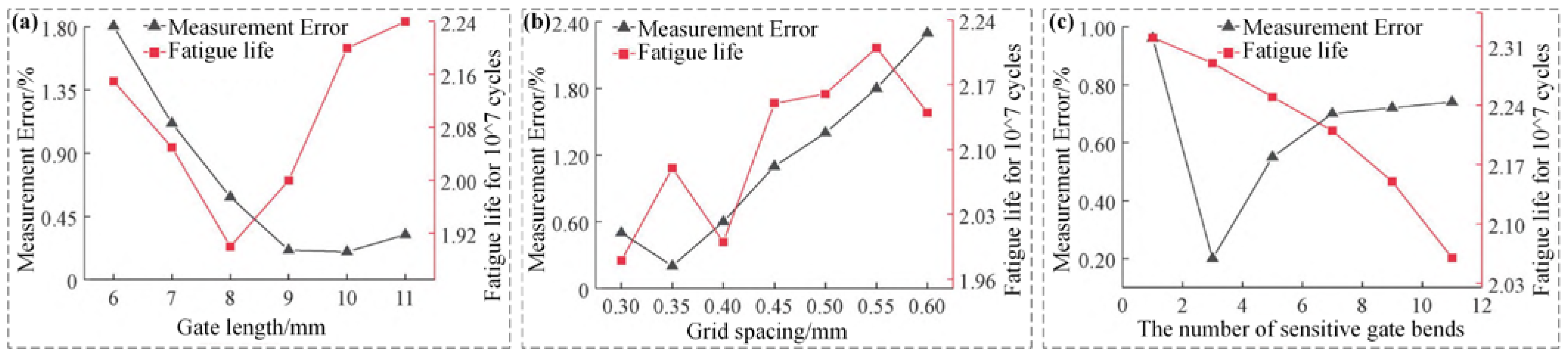
| Changes in Structural Parameters | Variation of Target Parameters (Measurement Accuracy/Fatigue Life) | Another Structural Parameter Affects |
|---|---|---|
| (5–11 mm) increase | Measurement accuracy decreases and then increases | and affect the value of the maximum value of measurement accuracy. |
| (0.3–0.6 mm) increase | Measurement accuracy decreases | affects the rate at which measurement accuracy decreases with increasing . |
| (1–11) increase | Measurement accuracy decreases and then levels off | . |
| (5–11 mm) increase | reaches 10 mm. | |
| (0.3–0.6 mm) increase | is 7. | |
| (1–11) increase | of 9 mm, the fatigue life increases and then decreases. | |
| Technology | Advantages | Disadvantages | Application | Reference |
|---|---|---|---|---|
| Optical Fiber Method | EMI-resistant, multi-point measurement, corrosion-resistant. | Significant temperature effects, complex temperature compensation required, poor stability at high temperatures. | Electromagnetic interference environment, low strain detection | [69,70] |
| Laser Speckle Method | Full-field measurement, non-contact | Requires stable light source, complex data processing, low repeatability | Dynamic strain on flat surfaces | [71] |
| Digital Image Correlation (DIC) | Non-contact, full-field measurement, 3D reconstruction | Requires surface texture, light-sensitive, limited to surface strain | Surface strain under visible light (<800 °C) | [72] |
| Surface Acoustic Wave (SAW) | Wireless/passive, high-temp resistant (up to 1200 °C) | Complex fabrication, difficult calibration, high cost | Rotating components | [73] |
Disclaimer/Publisher’s Note: The statements, opinions and data contained in all publications are solely those of the individual author(s) and contributor(s) and not of MDPI and/or the editor(s). MDPI and/or the editor(s) disclaim responsibility for any injury to people or property resulting from any ideas, methods, instructions or products referred to in the content. |
© 2025 by the authors. Licensee MDPI, Basel, Switzerland. This article is an open access article distributed under the terms and conditions of the Creative Commons Attribution (CC BY) license (https://creativecommons.org/licenses/by/4.0/).
Share and Cite
Wang, W.; Zong, R.; Li, D.; Zhang, J.; Teng, G.; Li, S. High-Temperature Strain Gauge Measurement Techniques for Temperatures Above 800 °C: A Review. Materials 2025, 18, 1588. https://doi.org/10.3390/ma18071588
Wang W, Zong R, Li D, Zhang J, Teng G, Li S. High-Temperature Strain Gauge Measurement Techniques for Temperatures Above 800 °C: A Review. Materials. 2025; 18(7):1588. https://doi.org/10.3390/ma18071588
Chicago/Turabian StyleWang, Wenrui, Rui Zong, Dongyue Li, Jiaming Zhang, Guangrong Teng, and Shengxiang Li. 2025. "High-Temperature Strain Gauge Measurement Techniques for Temperatures Above 800 °C: A Review" Materials 18, no. 7: 1588. https://doi.org/10.3390/ma18071588
APA StyleWang, W., Zong, R., Li, D., Zhang, J., Teng, G., & Li, S. (2025). High-Temperature Strain Gauge Measurement Techniques for Temperatures Above 800 °C: A Review. Materials, 18(7), 1588. https://doi.org/10.3390/ma18071588