

Oxidation of the Alloy Based on the Intermetallic Phase FeAl in the Temperature Range of 700–1000 °C in Air and Possibilities of Practical Application

 , , , , and
Highlights
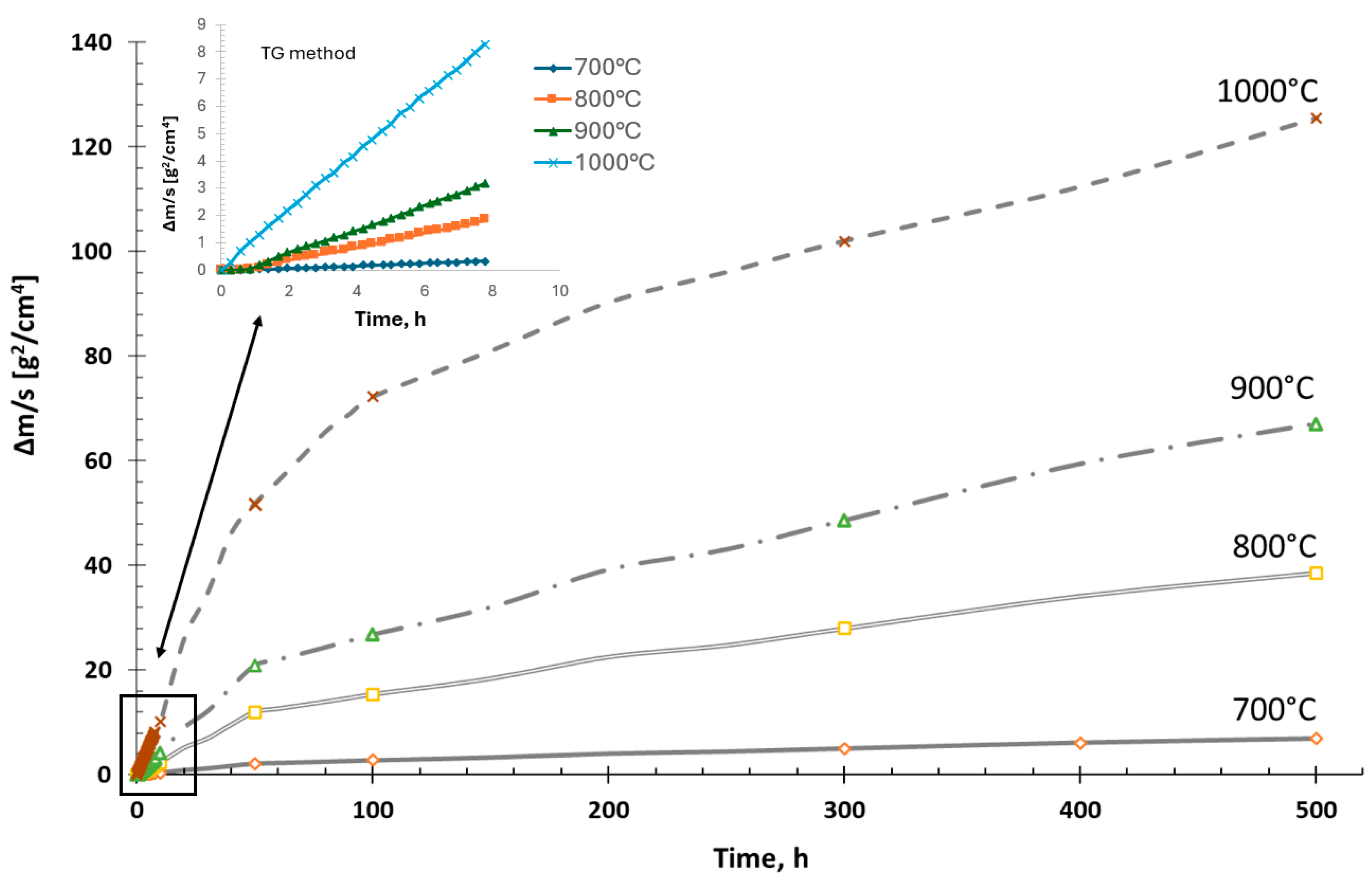
- The Fe40Al5Cr0.2TiB alloy, oxidized in the temperature range of 700–1000 °C was characterized by parabolic oxidation kinetics. This resulted from the formation of a passive Al2O3 layer on the surface, which slowed down the corrosion process.
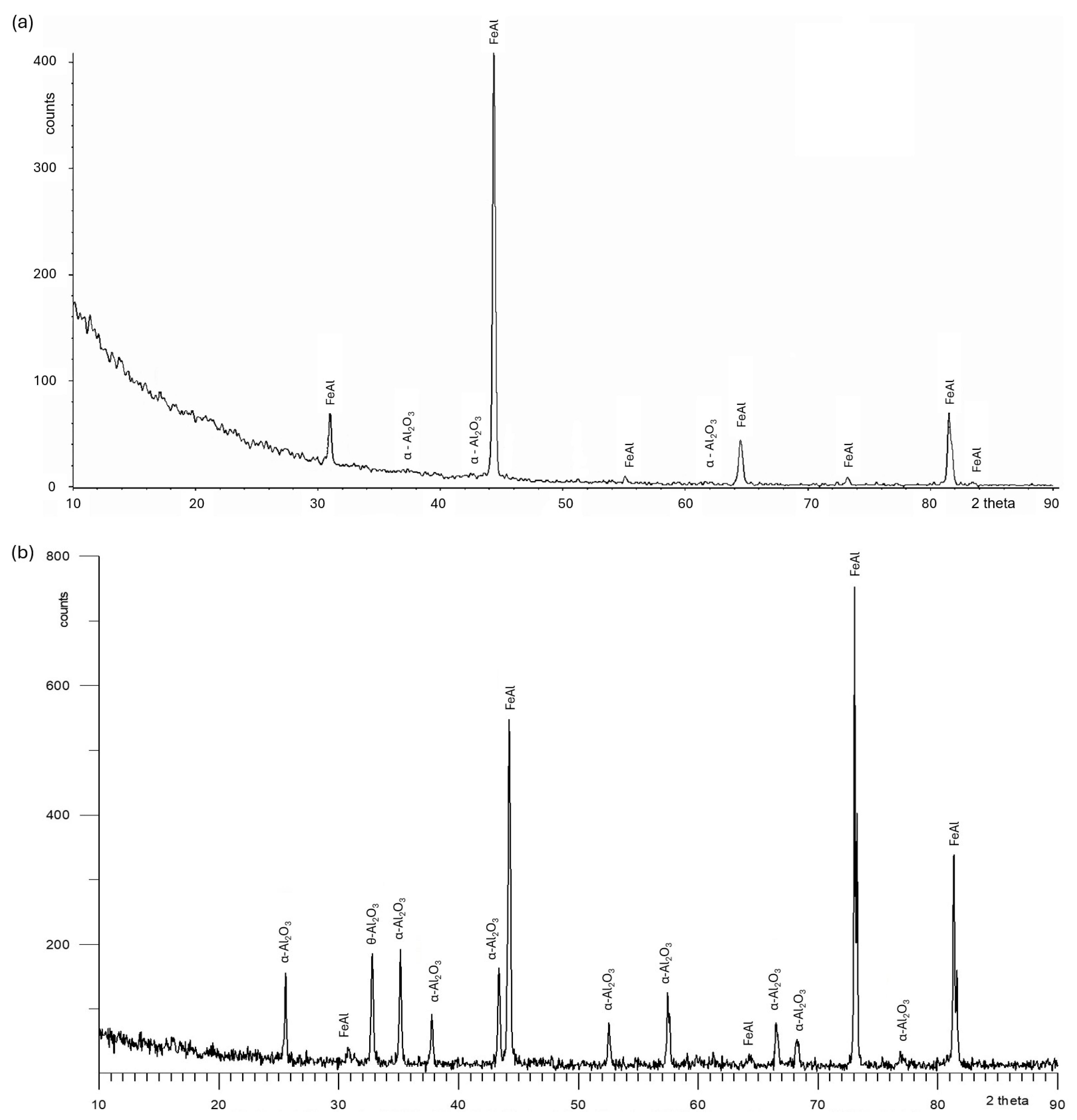
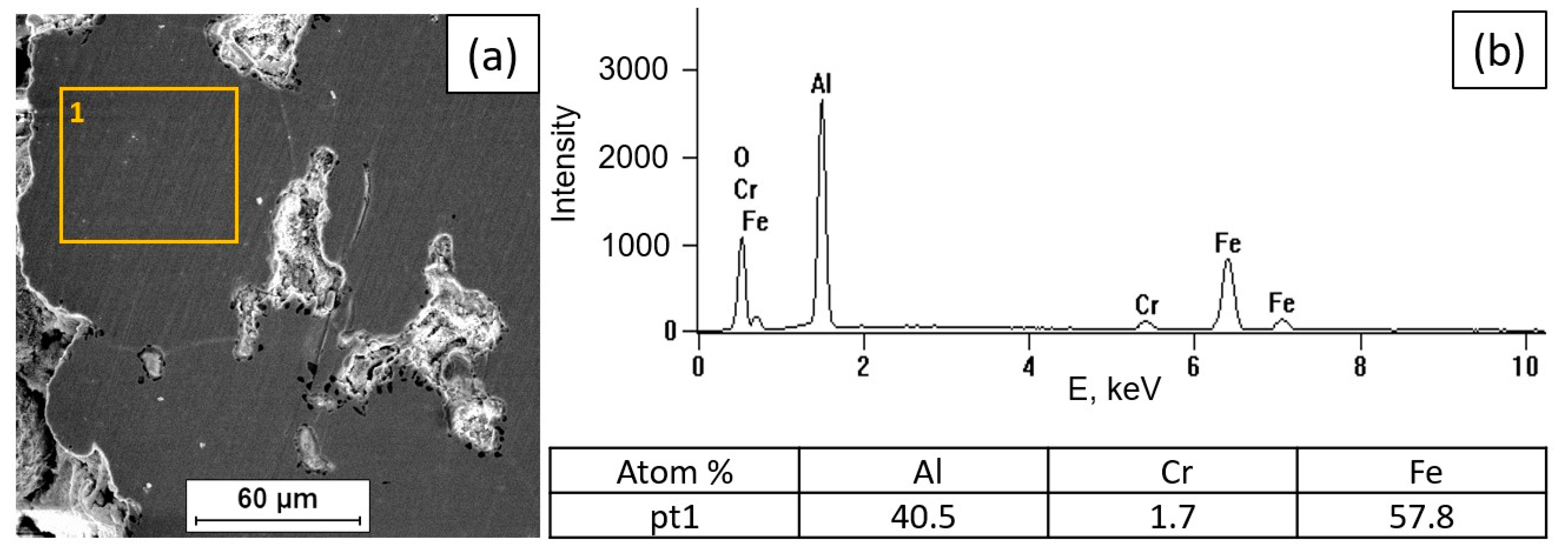
- At 700 °C, a small share of oxides on the surface was demonstrated.
- Due to the good resistance of the material under high-temperature oxidation conditions, an attempt was made to use the material as a surfacing layer on structural steel intended for use at elevated temperatures.
Abstract
1. Introduction
2. Materials and Methods
3. Results and Discussion
3.1. Oxidation Kinetics of Fe40Al5Cr0.2TiB Alloy
3.2. Tests of the Surface Condition and Oxidation Products of the Fe40Al5Cr0.2TiB Alloy
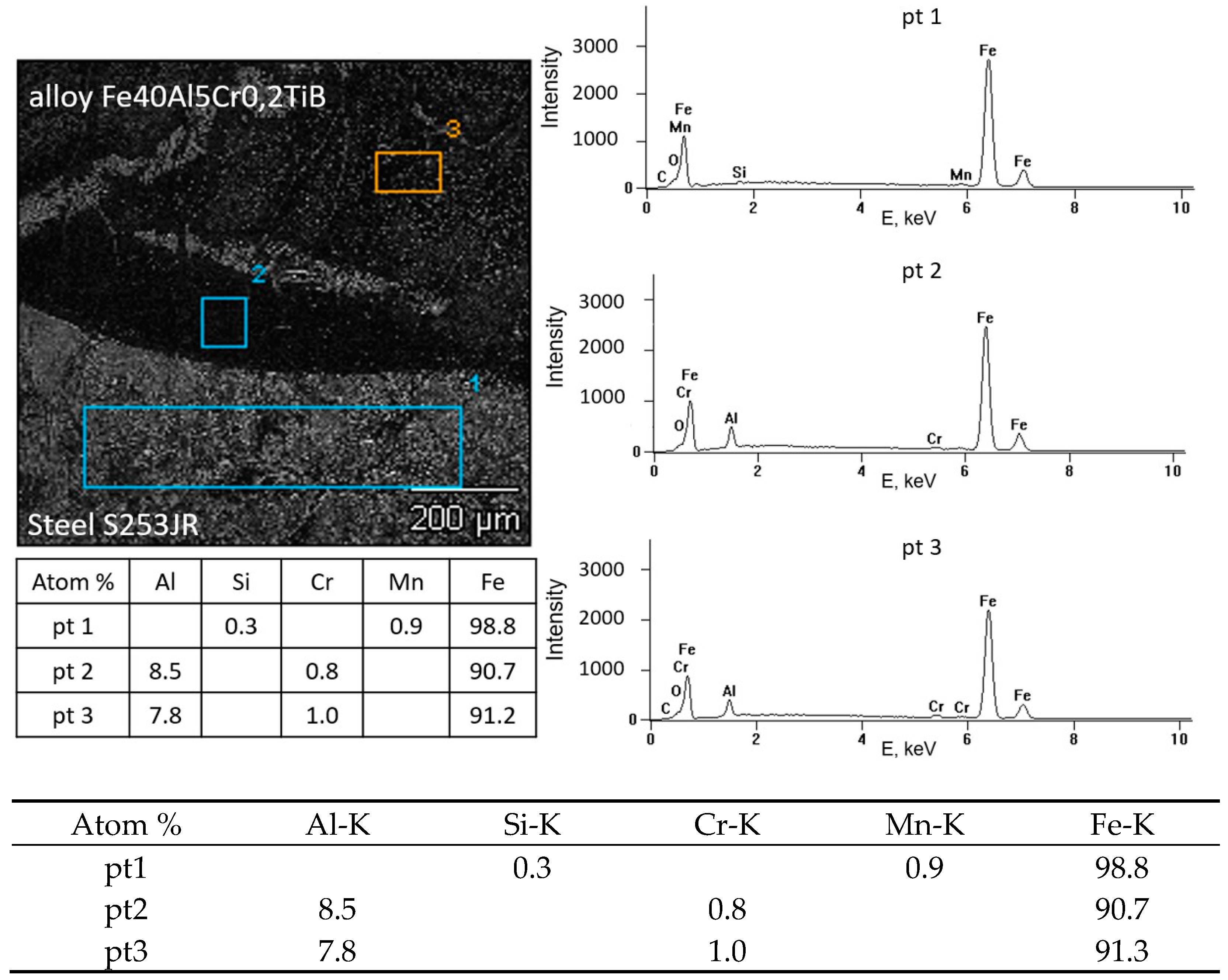
3.3. Possibility of Making a Coating of FeAl Intermetallic Alloy on a Structural Steel Substrate by the Surfacing Method
4. Conclusions
- Processes related to the formation of a protective oxide layer do not occur significantly at a temperature of 700 °C. The surface of the sample at this temperature is not covered with an oxide layer compared to the state of the surface of the alloy oxidized in the range of 800–1000 °C.
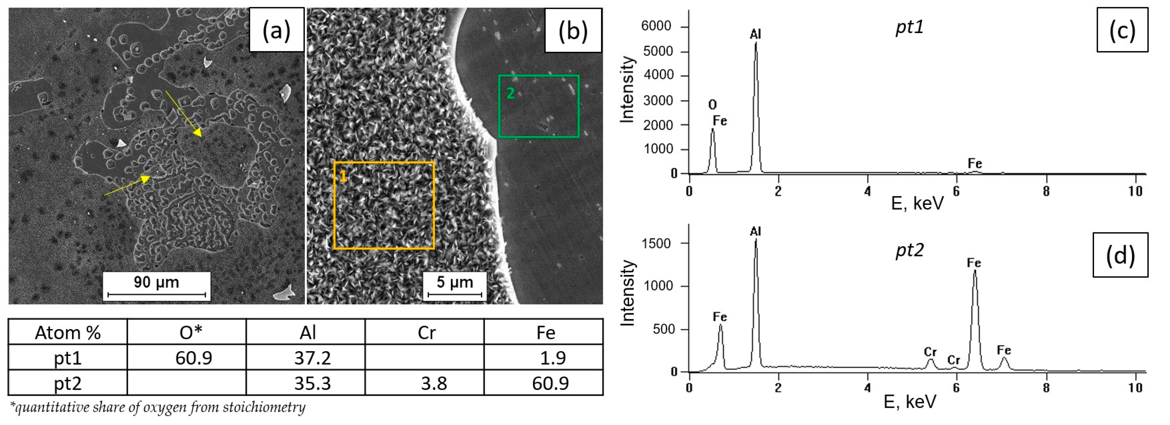
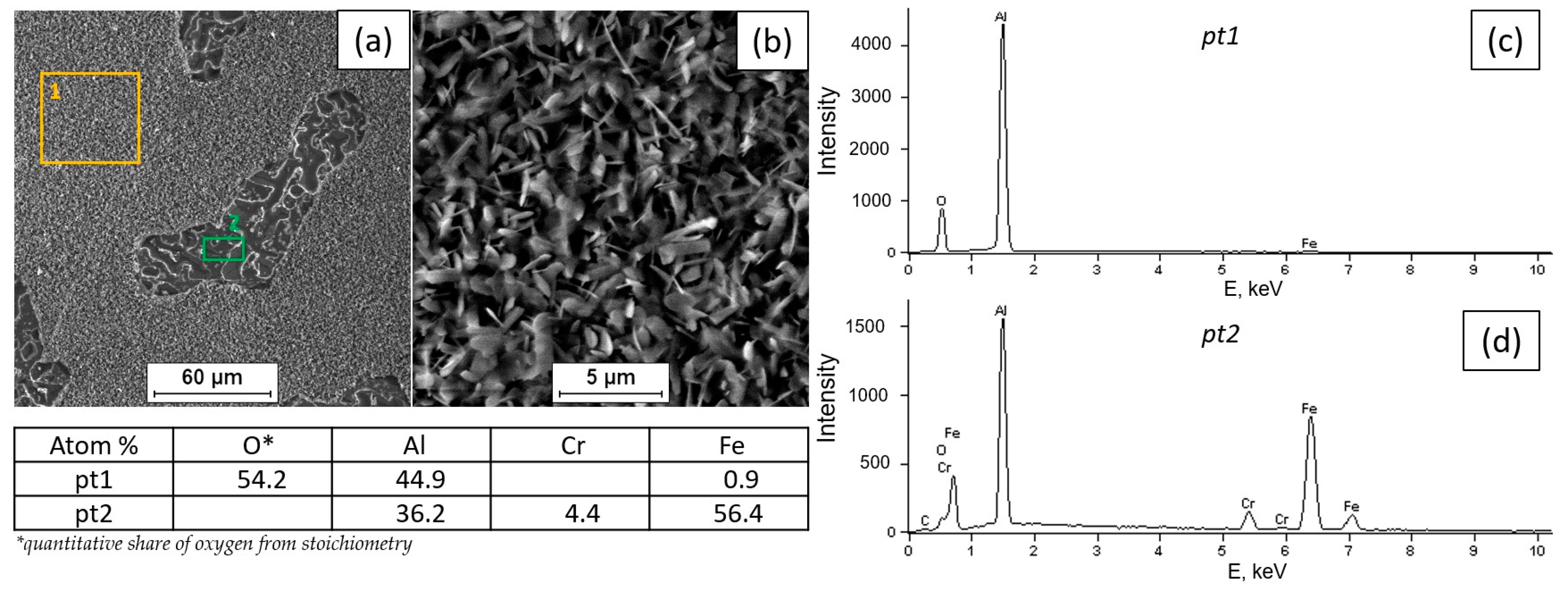
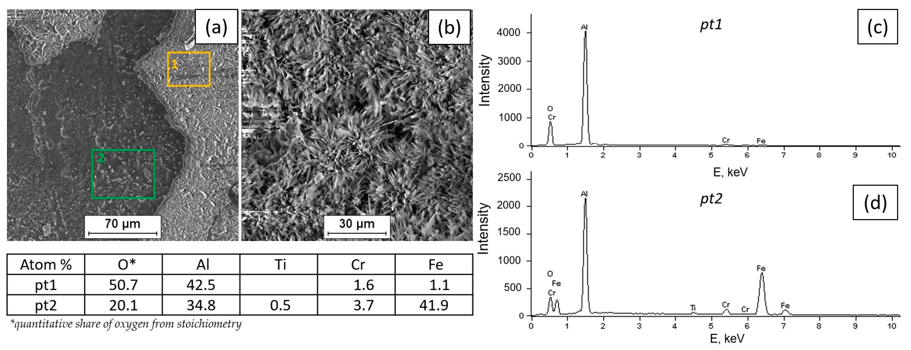
- The formation of the Al2O3 scale begins at a temperature lower than 800 °C, while the oxidation process intensifies in the range of 800–1000 °C.
- The surface of the alloy at 800 °C is covered with scale, which is aluminum oxide with a needle morphology.
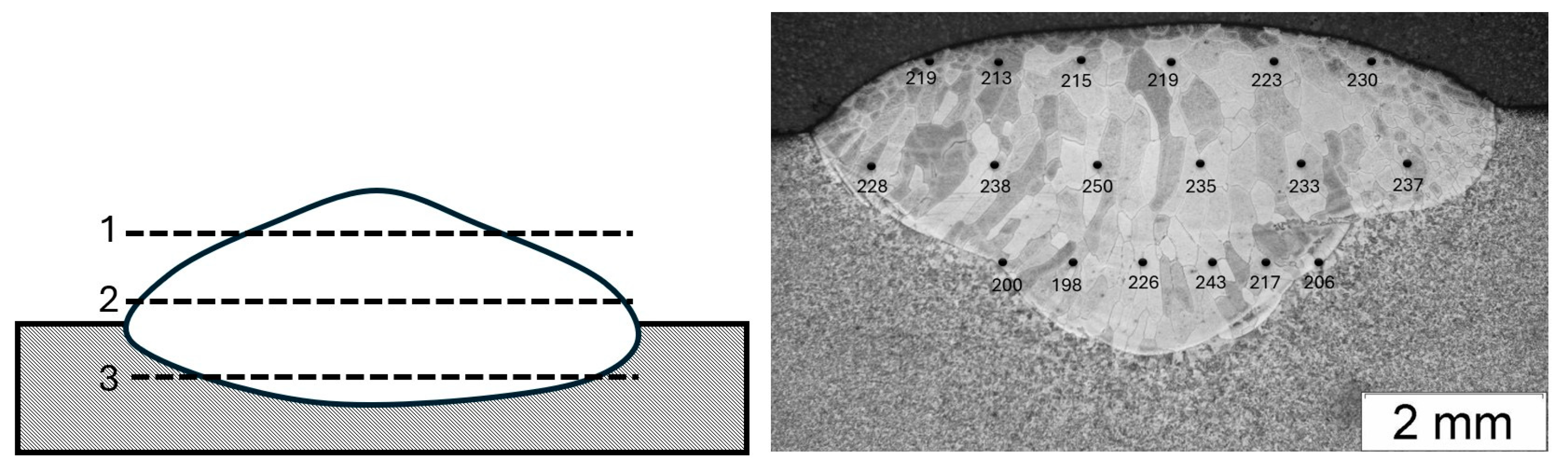
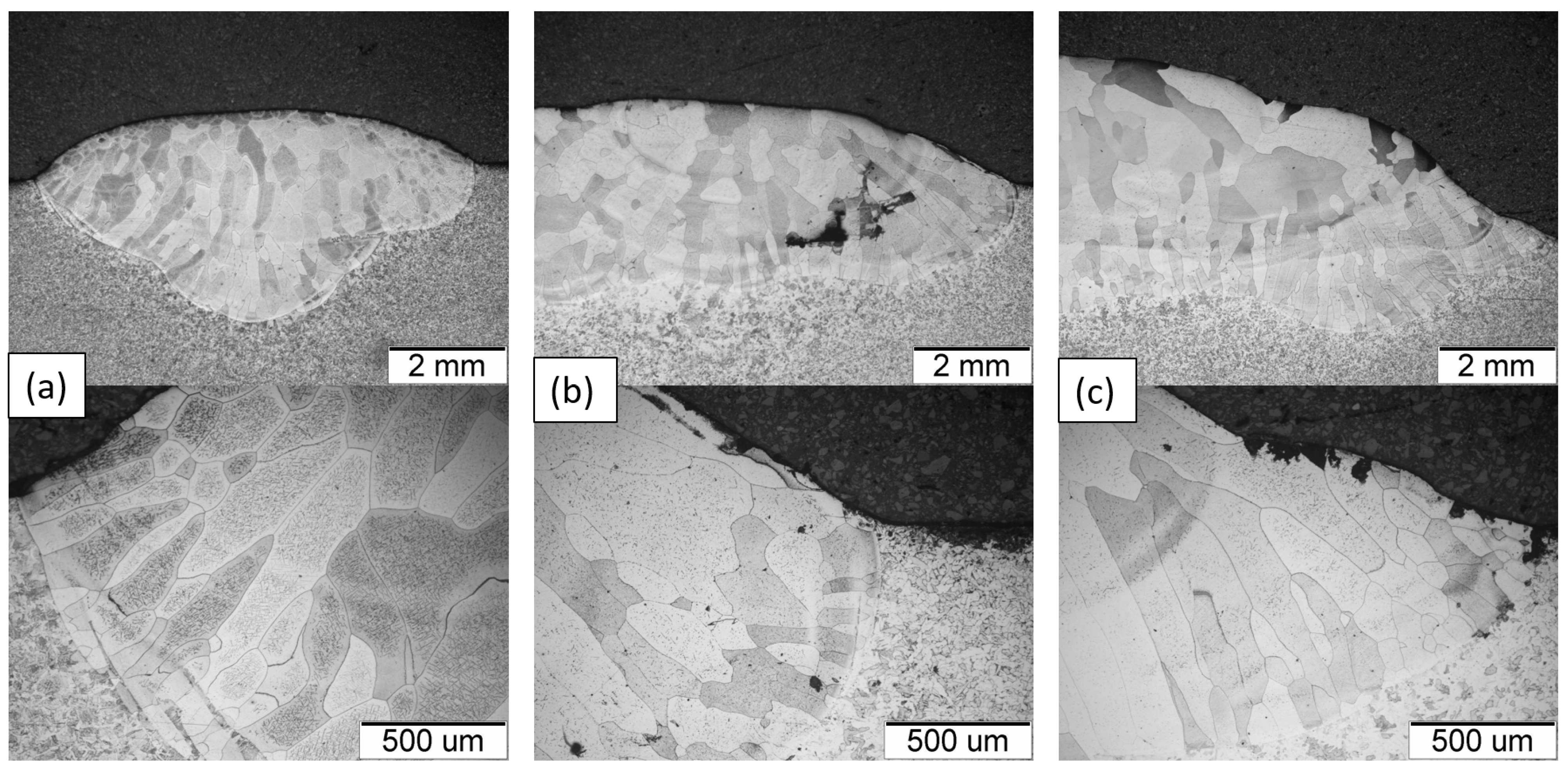
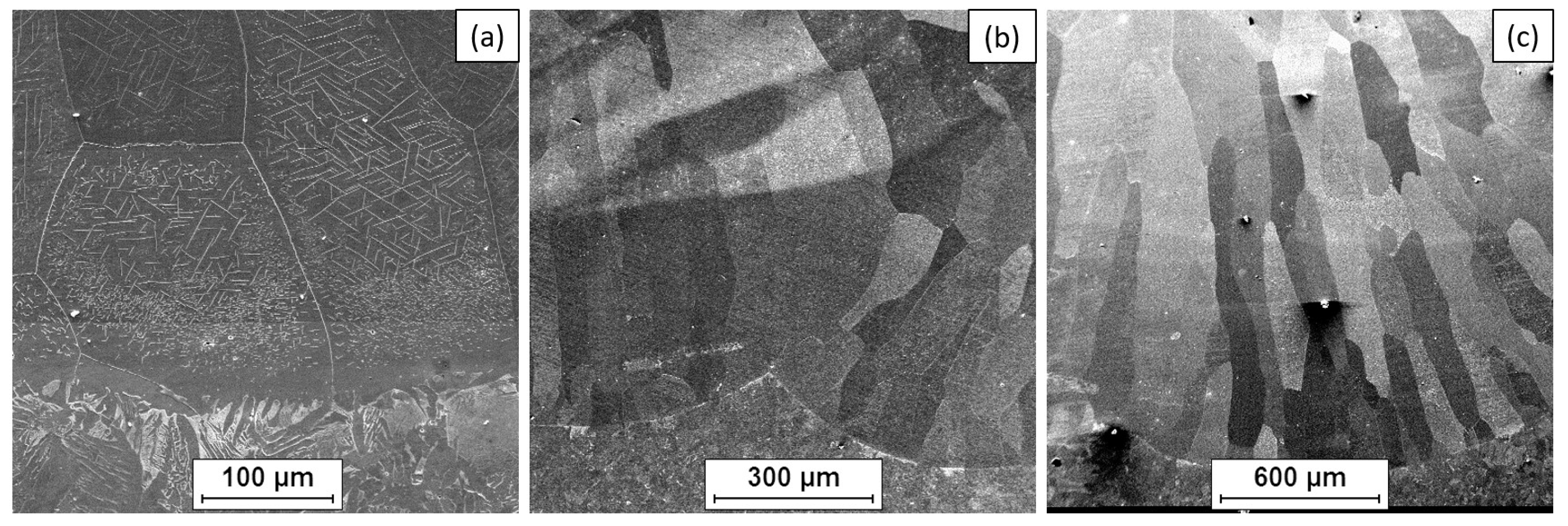
- The microstructure of the Fe40Al5CrTiB alloy was changed after the welding process. The microscopic grains grow and form a coarse-grained structure of the material. The gas tungsten arc welding process is possible to use for making an intermetallic surface FeAl. The test results show that DC current can be used to burn this kind of material, but in the cross-section of the clad, we can look at several kinds of welding imperfections, such as pores and lack of fusion. This kind of imperfection is located on or near to fusion line. If we made multi-beads or multi-layers, this kind of imperfection would have been reduced. Only the first layer has imperfections; the next bead or layer is without this kind of defect.
- The proposed method of producing alloy layers based on the intermetallic FeAl phase may be an alternative to currently used methods of modifying steel surfaces, based on covering them with expensive coating materials or using advanced technologies, e.g., thermal spraying.
- As a result of surfacing, aluminum evaporates; therefore, it is important to select appropriate process parameters or use a material that provides the required chemical composition of the surfacing layer.
Author Contributions
Funding
Institutional Review Board Statement
Informed Consent Statement
Data Availability Statement
Conflicts of Interest
References
- Hernas, A. Uwarunkowania i kierunki rozwoju materiałów żarowytrzymałych. In Postępy Nauki o Materiałach i Inżynierii Materiałowej; Hetmańczyk, M., Cwajna, J., Czyrska-Filemonowicz, A., Kurzydłowski, K.J., Hernas, A., Sieniawski, J., Wierzchoń, T., Eds.; Wydawnictwo Politechniki Śląskiej: Gliwice, Poland, 2002; pp. 191–230. [Google Scholar]
- Mrowec, S.; Werber, T. Gas Corrosion; Silesia Publishing House: Katowice, Poland, 1965. [Google Scholar]
- Niewielski, G.; Jabłońska, M. Characteristics and applications of intermetallics from the Fe-Al system. Mater. Eng. 2011, 2, 43–47. [Google Scholar]
- Deevi, S.C.; Sikka, V.K. Nickel and iron aluminides: An overview on properties, processing, and applications. Intermetallics 1996, 4, 357–375. [Google Scholar] [CrossRef]
- Zhang, H.; Xie, W.; Gao, H.; Shen, W.; He, Y. Suppression of the SHS reactions during synthesis of porous FeAlintermetallics by introducing silicon. J. Alloys Compd. 2018, 735, 1435–1438. [Google Scholar] [CrossRef]
- Josh, D.L.; Easton, D.S.; Liu, C.T.; Babu, S.S.; David, S.A. Processing of FeAl and FeAl alloys by reaction synthesis. Intermetallics 1995, 3, 467–481. [Google Scholar]
- Siemiaszko, D.; Mościcki, R. Kinetics study on the SHS reaction in massive samples with high heating rate in the Fe–Al system. J. Alloys Compd. 2015, 632, 335–342. [Google Scholar] [CrossRef]
- Baligidad, R.G.; Prakash, U.; Rao, R.V.; Rao, P.K.; Ballal, N.B. Processing of Fe3Al based intermetallic alloys through electroslag remelting. ISIJ Int. 1996, 36, 1448–1452. [Google Scholar] [CrossRef]
- Sikka, V.K.; Wilkening, D.; Liebetrau, J.; Mackey, B. Melting and casting of FeAl-based cast alloy. Mater. Sci. Eng. 1998, A258, 229–235. [Google Scholar] [CrossRef]
- Pęska, M.; Karczewski, K.; Rzeszotarska, M.; Polański, M. Direct Synthesis of Fe-Al Alloys from Elemental Powders Using Laser Engineered Net Shaping. Materials 2020, 13, 531. [Google Scholar] [CrossRef]
- Garbacz, H.; Wyrzykowski, J. Modern methods of plasticizing alloys based on ordered Ti-Al intermetallic phases. Mater. Eng. 1997, 3, 86–91. [Google Scholar]
- Huang, D.; Yang, W.Y.; Sun, Z.Q.; Froyen, L. Preparation and mechanical properties of large-ingot Fe3Al-based alloys. J. Mater. Process. Technol. 2004, 146, 175–180. [Google Scholar] [CrossRef]
- Kupka, M. Structure and Properties of FeAl-Based Alloys Obtained in Metallurgical Processes; University of Silesia Publishing House: Katowice, Poland, 2005. [Google Scholar]
- Bojar, Z.; Przetakiewicz, W. Metal Materials Containing Intermetallic Phases; BEL Studio: Warsaw, Poland, 2006; ISBN 83-89968-03-7. [Google Scholar]
- Dymek, S. Characteristics of high-temperature intermetallic compounds. Steelmak.–Steelmak. News 1998, 6, 220–222. [Google Scholar]
- Kulak, K.; Kupka, M. Oxidation of multi-component iron aluminum on the FeAl matrix. Mater. Eng. 2011, 4, 514–518. [Google Scholar]
- Morris, D.G.; Deevi, S.C.; Sikka, V.K.; Maziasz, P.J.; Cahn, R.W. International Symposium on Nickel and Iron Aluminides; ASM International: Materials Park, OH, USA, 1997; pp. 165–175. [Google Scholar]
- Cebulski, J.; Bęczkowski, R.; Pasek, D. Heat resistance of Fe40Al5Cr0.2TiB alloy intermetallic surface remelted with TIG method. In Proceedings of the 27th International Conference on Metallurgy and Materials, Brno, Czech Republic, 23–25 May 2018. [Google Scholar]
- Jaśkowiec, K.; Uhl, W. The problem of casting elements from an alloy based on Fe-Al operating at elevated temperatures. MOTROL Comm. Mot. Energetics Agric. 2013, 15, 59–62. [Google Scholar]
- Matysik, P.; Jóźwiak, S.; Czujko, T. Characterization of Low-Symmetry Structures from Phase Equilibrium of Fe-Al System-Microstructures and Mechanical Properties. Materials 2015, 8, 914–931. [Google Scholar] [CrossRef]
- Cinca, N.; Cygan, S.; Senderowski, C.; Jaworska, L.; Dosta, S.G.; Cano, I.; Guilemany, J.M. Sliding Wear Behavior of Fe-Al Coatings at High Temperatures. Coatings 2018, 8, 268. [Google Scholar] [CrossRef]
- Seikh, A.H.; Baig, M.; Singh, J.K.; Mohammed, J.A.; Luqman, M.; Abdo, H.S.; Khan, A.R.; Alharthi, N.H. Microstructural and Corrosion Characteristics of Al-Fe Alloys Produced by High-Frequency Induction-Sintering Process. Coatings 2019, 9, 686. [Google Scholar] [CrossRef]
- Morris, D.G.; Munoz-Morris, M.G.; Requejo, L.M. Work hardening in Fe-Al alloys. Mater. Sci. Eng. A 2007, 460–461, 163–173. [Google Scholar] [CrossRef]
- Zhang, Y.; Zhao, T.; Yu, X.; Huang, J. The Al-Fe Intermetallic Compounds and the Atomic Diffusion Behavior at the Interface of Aluminum-Steel Welded Joint. Metals 2023, 13, 334. [Google Scholar] [CrossRef]
- Zhang, J.; Sun, K.; Wang, J.; Tian, B.; Wang, H.; Yin, Y. Sliding wear behavior of plasma sprayed Fe3Al-Al2O3 graded coatings. Thin Solid Film. 2008, 516, 5681–5685. [Google Scholar] [CrossRef]
- Formanek, B.; Szczucka-Lasota, B.; Szymański, K.; Włodarczyk, A. New generation of protective coatings intended for the power industry. J. Mater. Process. Technol. 2005, 5, 164–165. [Google Scholar] [CrossRef]
- Cinca, N.; Dosta, S.; Guilemany, J.M.; Lima, C.R.C. High-temperature oxidation of Fe40Al coatings obtained by HVOF thermal spray. Intermetallics 2007, 15, 1384–1394. [Google Scholar]
- Zienert, T.; Leineweber, A.; Fabrichnaya, O. Heat capacity of Fe-Al intermetallics: B2-FeAl, FeAl2, Fe2Al5 and Fe4Al13. J. Alloys Compd. 2017, 725, 848–859. [Google Scholar] [CrossRef]
- Bojar, Z.; Senderowski, C. Gas detonation spray forming of Fe-Al coatings in the presence of interlayer. Surf. Coat. Technol. 2008, 202, 3538–3548. [Google Scholar]
- Kumar, M.; Kant, R.; Chand, S.; Prakash, U.; Sehgal, S.; Saxena, K.K.; Davim, J.P.; Prakash, C. High-Temperature Corrosion Performance of FeAl-Based Alloys Containing Carbon in Molten Salt. Metals 2011, 11, 2040. [Google Scholar] [CrossRef]
- Guilemany, J.M.; Nin, J. Thermal spraying methods for protection against wear. In Sufface Coatings for Protection Against Wear; Mellor, B.G., Ed.; Woodhead: Cambridge, UK, 2006. [Google Scholar]
- Peng, J.; Moszner, F.; Rechmann, J.; Vogel, D.; Palm, M.; Rohwerder, M. Influence of Al content and pre-oxidationon the aqueous corrosion resistance of binary Fe-Al alloys in sulphuric acid. Corros. Sci. 2019, 149, 123–132. [Google Scholar] [CrossRef]
- Amaya, M.; Espinosa-Medina, M.A.; Porcayo-Calderon, J.; Martinez, L.; Gonzalez-Rodriguez, J.G. High temperature corrosion performance of FeAl intermetallic alloys in molten salts. Mater. Sci. Eng. A 2003, 349, 12–19. [Google Scholar] [CrossRef]
- Novák, P.; Nová, K. Oxidation Behavior of Fe-Al, Fe-Si and Fe-Al-Si. Materials 2019, 12, 1748. [Google Scholar] [CrossRef]
- Bojar, Z.; Formanek, B.; Senderowski, C.; Szymański, K. Tribological behavior of Fe-Al intermetallic coatings obtained by HVOF method. Mater. Eng. 2010, 31, 390–393. [Google Scholar]
- Shishkovsky, I.; Missemer, F.; Kakovkina, N.; Smurov, I. Intermetallics Synthesis in the Fe–Al System via Layer by Layer 3D Laser Cladding. Crystals 2013, 3, 517–529. [Google Scholar] [CrossRef]
- Wang, H.; An, F.; Bai, X.; Yao, H.; Zhang, M.; Chen, Q.; Ji, G.; Ramachandran, C.S. Improvement of Microstructure and Sliding Wear Property of Cold-Sprayed FeAl Intermetallic Compound Coating by Annealing Treatment. Coatings 2023, 13, 1260. [Google Scholar] [CrossRef]
- Faria, J.; de Paula, A.; Silva, C.; Kakitani, R.; Barros, A.; Garcia, A.; Brito, C.; Cheung, N. Fe-Containing Al-Based Alloys: Relationship between Microstructural Evolution and Hardness in an Al-Ni-Fe Alloy. Metals 2023, 13, 1980. [Google Scholar] [CrossRef]
- Cebulski, J.; Pasek, D.; Popczyk, M.; Swinarew, A.; Gabor, J. Structure and Corrosion Resistance of Fe40Al5Cr0.2TiB Alloy After Casting and After Homogenization Annealing. Materials 2025, 18, 308. [Google Scholar] [CrossRef] [PubMed]
- Kulak, K.; Kupka, M.; Dercz, G. Oxidation of multicomponent iron aluminide based on FeAl phase. Mater. Eng. 2011, 4, 510–513. [Google Scholar]
- Barcik, J.; Cebulski, J. Plastify of alloy based on the matrix of intermetallic FeAl phase. Arch. Metall. 2000, 45, 315–330. [Google Scholar]
- Hernas, A.; Dobrzański, J.; Pasternak, J.; Fudali, S. Characteristics of the New Generation of Steel for the Energy Sector; Wydawnictwo Politechniki Śląskiej: Gliwice, Poland, 2015. [Google Scholar]
- Novák, P.; Michalcová, A.; Marek, I.; Mudrová, M.; Saksl, K.; Bednarčík, J.; Zikmund, P.; Vojtěch, D. On the formation of intermetallics in Fe-Al system—An in situ XRD study. Intermetallics 2013, 32, 127–136. [Google Scholar] [CrossRef]
- Cebulski, J.; Pasek, D.; Chmiela, B.; Popczyk, M.; Swinarew, A.S.; Stanula, A.; Waśkiewicz, Z.; Knechtle, B. Evaluation of Structure and Corrosion Behavior of FeAl Alloy after Crystallization, Hot Extrusion and Hot Rolling. Materials 2020, 13, 2041. [Google Scholar] [CrossRef]


| Compound | Fe | Al | Cr | Ti | B |
|---|---|---|---|---|---|
| % at. | 54.80 | 40.10 | 4.86 | 0.18 | 0.06 |
| Compound | C | Mn | P | S | Si | Fe |
|---|---|---|---|---|---|---|
| % mas. | 0.15 | 1.2 | <0.035 | <0.035 | 0.3 | rest |
| TIG | Thickness [mm] | Gas Shield | Current [A] | Flow Rate [L/min] | Welding Position | Welding Speed |
|---|---|---|---|---|---|---|
| DC- | 5 | Argon I1 | 100 | 10 | PA | 1.0–2.5 |
| Temperature [°C] | Rm [MPa] | Rp0.2 [MPa] | A5 [%] | Z [%] |
|---|---|---|---|---|
| Room | 312 | - | - | - |
| 700 | 268 | 172 | - | - |
| 800 | 115 | 77 | 3 | 21 |
| 900 | 53 | 43 | 7 | 35 |
| 1000 | 41 | 39 | 11 | 72 |
| Measurement | 1 | 2 | 3 | 4 | 5 | 6 |
|---|---|---|---|---|---|---|
| SB 1 | 219 | 213 | 215 | 219 | 223 | 230 |
| SB 2 | 228 | 238 | 250 | 235 | 233 | 237 |
| SB 3 | 200 | 198 | 226 | 243 | 217 | 206 |
| MB 1 | 321 | 286 | 280 | 334 | 275 | 331 |
| MB 2 | 289 | 257 | 313 | 295 | 292 | 278 |
| MB 3 | 265 | 297 | 238 | 226 | 260 | 240 |
| ML 1 | 302 | 345 | 292 | 297 | 299 | 301 |
| ML 2 | 297 | 342 | 323 | 312 | 278 | 316 |
| ML 3 | 248 | 224 | 236 | 241 | 231 | 249 |
Disclaimer/Publisher’s Note: The statements, opinions and data contained in all publications are solely those of the individual author(s) and contributor(s) and not of MDPI and/or the editor(s). MDPI and/or the editor(s) disclaim responsibility for any injury to people or property resulting from any ideas, methods, instructions or products referred to in the content. |
© 2025 by the authors. Licensee MDPI, Basel, Switzerland. This article is an open access article distributed under the terms and conditions of the Creative Commons Attribution (CC BY) license (https://creativecommons.org/licenses/by/4.0/).
Share and Cite
Cebulski, J.; Pasek, D.; Sozańska, M.; Popczyk, M.; Gabor, J.; Swinarew, A. Oxidation of the Alloy Based on the Intermetallic Phase FeAl in the Temperature Range of 700–1000 °C in Air and Possibilities of Practical Application. Materials 2025, 18, 1835. https://doi.org/10.3390/ma18081835
Cebulski J, Pasek D, Sozańska M, Popczyk M, Gabor J, Swinarew A. Oxidation of the Alloy Based on the Intermetallic Phase FeAl in the Temperature Range of 700–1000 °C in Air and Possibilities of Practical Application. Materials. 2025; 18(8):1835. https://doi.org/10.3390/ma18081835
Chicago/Turabian StyleCebulski, Janusz, Dorota Pasek, Maria Sozańska, Magdalena Popczyk, Jadwiga Gabor, and Andrzej Swinarew. 2025. "Oxidation of the Alloy Based on the Intermetallic Phase FeAl in the Temperature Range of 700–1000 °C in Air and Possibilities of Practical Application" Materials 18, no. 8: 1835. https://doi.org/10.3390/ma18081835
APA StyleCebulski, J., Pasek, D., Sozańska, M., Popczyk, M., Gabor, J., & Swinarew, A. (2025). Oxidation of the Alloy Based on the Intermetallic Phase FeAl in the Temperature Range of 700–1000 °C in Air and Possibilities of Practical Application. Materials, 18(8), 1835. https://doi.org/10.3390/ma18081835