Article

An Adaptive Linear Programming Algorithm with Parameter Learning

1
Department of Industrial Engineering, South Dakota School of Mines and Technology, Rapid City, SD 57701, USA
2
Department of Mechanical and Civil Engineering, Florida Institute of Technology, Melbourne, FL 32901, USA
3
Engineering and Technology, University of New South Wales, Canberra 2600, Australia
4
The Systems Realization Laboratory, The University of Oklahoma, Norman, OK 73019, USA
*
Author to whom correspondence should be addressed.
Algorithms 2024, 17(2), 88; https://doi.org/10.3390/a17020088
Submission received: 24 December 2023 / Revised: 8 February 2024 / Accepted: 11 February 2024 / Published: 19 February 2024
(This article belongs to the Section Algorithms for Multidisciplinary Applications)

Abstract

:
When dealing with engineering design problems, designers often encounter nonlinear and nonconvex features, multiple objectives, coupled decision making, and various levels of fidelity of sub-systems. To realize the design with limited computational resources, problems with the features above need to be linearized and then solved using solution algorithms for linear programming. The adaptive linear programming (ALP) algorithm is an extension of the Sequential Linear Programming algorithm where a nonlinear compromise decision support problem (cDSP) is iteratively linearized, and the resulting linear programming problem is solved with satisficing solutions returned. The reduced move coefficient (RMC) is used to define how far away from the boundary the next linearization is to be performed, and currently, it is determined based on a heuristic. The choice of RMC significantly affects the efficacy of the linearization process and, hence, the rapidity of finding the solution. In this paper, we propose a rule-based parameter-learning procedure to vary the RMC at each iteration, thereby significantly increasing the speed of determining the ultimate solution. To demonstrate the efficacy of the ALP algorithm with parameter learning (ALPPL), we use an industry-inspired problem, namely, the integrated design of a hot-rolling process chain for the production of a steel rod. Using the proposed ALPPL, we can incorporate domain expertise to identify the most relevant criteria to evaluate the performance of the linearization algorithm, quantify the criteria as evaluation indices, and tune the RMC to return the solutions that fall into the most desired range of each evaluation index. Compared with the old ALP algorithm using the golden section search to update the RMC, the ALPPL improves the algorithm by identifying the RMC values with better linearization performance without adding computational complexity. The insensitive region of the RMC is better explored using the ALPPL—the ALP only explores the insensitive region twice, whereas the ALPPL explores four times throughout the iterations. With ALPPL, we have a more comprehensive definition of linearization performance—given multiple design scenarios, using evaluation indices (EIs) including the statistics of deviations, the numbers of binding (active) constraints and bounds, the numbers of accumulated linear constraints, and the number of iterations. The desired range of evaluation indices (DEI) is also learned during the iterations. The RMC value that brings the most EIs into the DEI is returned as the best RMC, which ensures a balance between the accuracy of the linearization and the robustness of the solutions. For our test problem, the hot-rolling process chain, the ALP returns the best RMC in twelve iterations considering only the deviation as the linearization performance index, whereas the ALPPL returns the best RMC in fourteen iterations considering multiple EIs. The complexity of both the ALP and the ALPPL is O(n2). The parameter-learning steps can be customized to improve the parameter determination of other algorithms.

1. Introduction

Solution algorithms for solving engineering design problems fall into two categories: (i) an optimizing strategy or (ii) a satisficing strategy. For typical engineering design problems with nonlinear, nonconvex properties that cannot be solved in a straightforward way using simplex, Lagrange multipliers, or other gradient-based solution algorithms, when applying the optimizing strategy, designers need to solve problems approximately, for example, using pattern search methods [1], particle swarm optimization [2], memetic algorithms [3], penalty function methods [4], or metaheuristic algorithms [5]. When methods in Category (i) are used, the solutions are desired to be near-Pareto solutions, often on or close to the boundary of the feasible space (bounded by constraints) but not necessarily at a vertex of the feasible space. Whereas when methods in Category (ii) are used, such as sequential linear programming [6] or FEAST [7], the solutions are always at one or multiple vertices of the linearized (approximated) solution space. Since the solution always includes a vertex, we are able to use information of the dual problem to explore the solution space [6]. Typically, in engineering design problems the number of constraints in the primal formulation exceeds the number of variables [8]. In these cases, solving the dual formulation is quicker [6]. For optimization strategies, there are state-of-the-art surveys summarizing and classifying linearization techniques thoroughly, such as in [9]. Linearization techniques are classified into two groups—nonlinear equations replaced by an exact equivalent LP formulation or linear approximations which find the equivalent of a nonlinear function with the least deviation around the point of interest or separate straight-line segments.
In this paper, our focus is on a method in Category (ii), the satisficing strategy, namely, the compromise decision support problem (cDSP) and adaptive linear programming (ALP) algorithm [6], because it is more appropriate for engineering design problems by giving satisficing solutions and exploring solution space. Satisficing solutions are near-optimal and on the vertices of the approximated linear problems. The reasons are summarized in Section 1.1 and Section 1.2.

1.1. Frame of Reference

There are special requirements for engineering design methods. Engineering design is a task that occupies multiple designers with different fields of expertise to make decisions that meet a variety of requirements [10]. Designers may define objective functions using different methods—utility theory [11], game theory [12], analytic hierarchy process (AHP) [13], Pareto-optimal methods [14], etc. For optimization problems with one or multiple objective function(s) to be minimized or maximized, one can define such problems based on maximization of expected utility. Designers accept assumptions and simplifications when using utility theory to manage a problem, sometimes without realizing it. Such assumptions include the abstraction of mathematical relationships between variables to be 100% accurate and not evolve, the levels of fidelity of different sub-models or segments of a model are the same, the design preferences among multiple objectives are fully captured, etc. [15]. For many problems, these assumptions are wrong and this may cause problems. For example, when implementing an optimal solution, a system may not give optimal output, because of the inaccurate equations used in the model, or because uncertainty breaks the equilibrium of any Karush–Kuhn–Tucker (KKT) conditions, thus destroying the optimality of the solution [16].
In addition, when the problem is nonconvex, specifically, when any nonzero linear combination of the constraints is more convex than the objective function [17], Category (i) methods cannot return a feasible solution because the sufficient KKT condition cannot be satisfied [15]. In this case, formulating the problem using the compromise decision support problem (cDSP) and solving it using the adaptive linear programming (ALP) algorithm is a way to identify satisficing solutions that meet the necessary KKT condition [15].

1.2. Mechanisms to Ensure That the cDSP and ALP Find Satisficing Solutions

There are five mechanisms in the cDSP and ALP that enable designers to identify satisficing solutions to nonlinear, nonconvex engineering design problems, especially when optimization methods fail. We summarize the mechanisms in Table 1. Two assumptions in standard optimization methods make optimal solutions unavailable for some nonlinear, nonconvex problems:
Assumption 1.
Mathematical models are 100% complete and accurate abstractions of physical models, so the optimal solution to the mathematical problem is optimal for the physical problem.
Assumption 2.
The convexity degree of at least one nonzero linear combination of all constraints is higher than the convexity degree of the objective function.
However, for Assumption 1, designers need boundary information to deal with uncertainties, but such information is normally unavailable [18]. Using the cDSP and ALP, designers can identify satisficing solutions by removing the two assumptions.
There are differences between the satisficing construct using cDSP-ALP and optimization including its variant goal programming. Solutions are usually obtained by identifying the Pareto frontier consisting of nondominated or near-optimal solutions using optimization solution algorithms. The formulation of design problems using a satisficing strategy, namely, the compromise decision support problem (cDSP), has the key features that allow designers to identify satisficing solutions that meet the necessary KKT condition but not the sufficient condition.
The format of a nonlinear optimization problem is this: for a given objective function f x , Euler and Lagrange developed the Euler–Lagrange equation forming the second-order ordinary differential equations xx 2 f x to facilitate finding the stationary solutions. The value of the variables that maximize f x within the feasible set F is the solution to the optimization problem, where F is the set bounded by constraints and bounds. The format of an optimization problem O can be represented as follows. x is the vector of decision variables as real numbers. g i x is the ith inequality constraint. h j x is the ith equality constraint. Any point x that is a local extremum of the set mapped by multiplying active equations with a nonnegative vector is a local optimum of O [19], denoted as x * . The elements of such a nonnegative vector are Lagrange multipliers, μ and λ.
The format of an optimization problem O :
Given
f :   R n R , F R n F = x R n | g i x 0 ,   i = 1 , , m , h j x = 0 ,   j = 1 , ,
find
x * :   f x * f x ,   x F
One variant of optimization is goal programming. The format of a goal programming problem O goal is represented as follows. A target value T is predefined for the objective function f x as the right-hand side value, so the objective becomes an equation, and we call it a goal. d and d + are deviation variables measuring the underachievement and overachievement of the goal towards its target. The problem is solved by minimizing the deviation variables, which is minimizing the difference between f x and T . In other words, goal programming is aimed at finding T ’s closest projection on F .
The format of a goal programming problem O goal :
Given
f :   R n R , F R n F = x R n | g i x 0 ,   i = 1 , , m , h j x = 0 ,   j = 1 , , , d · d + = 0 ,   0 d 1 , Goal :   f x + d d + = T
find
x * : P x F Goal :   f x = T
In the cDSP, elements of mathematical programming and goal programming are combined. A cDSP C is represented as follows. For a nonlinear cDSP, we first linearize the nonlinear equations, including nonlinear constraints and nonlinear goal. Therefore, the nonlinear cDSP first becomes a linear problem with a linear goal Goal linear , a linear feasible space F li bounded by linear constraints g x li 0 and h x li = 0 . Thus, using a cDSP, we seek the closest projection from the linear goal set onto a linear feasible set. We define the solution as a satisficing solution, and we use x s to denote it.
The format of a cDSP C :
Given
f :   R n R , F R n F li = x R n | g i x li 0 ,   i = 1 , , m , h j x li = 0 ,   j = 1 , , , d · d + = 0 ,   0 d 1 , Goal li : f x li T + d d + = 1
find
x s : P x F li Goal li : f x li = T
The difference between x * and x s is that x * conforms to both the necessary (first-order) and sufficient (second-order) KKT conditions, whereas x s conforms to the necessary KKT condition but may not conform to the sufficient KKT condition. This is because the second derivative of the linear equations, Goal li , g i x li 0 , and h j x li = 0 , degenerates—as a result, no uncertainty may affect the feasibility of x s because there is no uncertainty to break the equilibrium of the second-order Lagrange equation. In addition, when the convexity of F is greater than the convexity of the f x , x * may not be identified as the second-order Lagrange equation has no solution, but x s is obtainable because the second-order KKT condition is irrelevant. The relationship among optimal solutions, satisficing solutions, and near-optimal solutions is illustrated in Figure 1.
In Chapter 2 of [15], the author gives five examples to demonstrate how the mechanisms work (we have a demonstration of the comparison of five examples in this video: https://www.youtube.com/watch?v=7apDZO-9A74, accessed on 21 November 2020, and a tutorial of using DSIDES to formulate and solve a problem in this video: https://www.youtube.com/watch?v=tUpVC97Y1L8, accessed on 25 November 2020. In this paper, since our focus is to fill a gap in the ALP, we give only one example in Section 1.3 to show one of the advantages versus the optimization method. Information such as applications using cDSP and ALP to obtain satisficing solutions can be found in [20].

1.3. An Example and Explanation Using KKT Conditions

We use a simple example with multiple goals (objectives), nonlinear and nonconvex equations, and the goal targets with various degrees of achievability. We formulate the problem using optimization and the cDSP in Table 2.
The methods used in the optimizing and satisficing strategies are listed in Table 3. For optimizing methods, we used the “SciPy.optimize” package (https://docs.scipy.org/doc/scipy/reference/optimize.html, accessed on 1 January 2008). There are ten algorithms in the package. We use three of them to solve the example problem because they are the only relevant ones. We do not use the Nelder–Mead, Powell (Powell’s conjugate direction method) [21], or conjugate gradient (CG) methods [22] or the Broyden–Fletcher–Coldfarb–Shannon (BFGS) algorithm [23] because they cannot easily manage problems with constraints. The Newton conjugate gradient (Newton-CG) method [24,25], L-BFGS-B (an extension BFGS for large-scale, bounded problems) [26], and TNC (truncated Newton method or Hessian-free optimization) [26] either cannot deal with problems without Jacobians (when using Newton-CG, even setting the Jacobian as false, and the algorithm may not work without a provided Jacobian partially because the default temporary memory of Jacobian cannot be cleared; see: https://stackoverflow.com/questions/33926357/jacobian-is-required-for-newton-cg-method-when-doing-a-approximation-to-a-jaco, accessed on 15 May 2019) or return infeasible solutions without recognizing that they are infeasible. Therefore, in SciPy we use the constrained optimization by linear approximation (COBYLA) algorithm [27,28], Trust-constr (https://docs.scipy.org/doc/scipy/reference/optimize.minimize-trustconstr.html, accessed on 1 January 2008), and sequential least squares programming (SLSQP) (https://docs.scipy.org/doc/scipy/reference/optimize.minimize-slsqp.html, accessed on 1 January 2008) to solve the example problem.
We select nondominated sorting genetic algorithm II (NSGA II) [29] as a verification method to compare and evaluate the performance of our selected optimization methods and the satisficing method in Table 3. We choose NSGA II as the verification method because it can solve problems with the complexities of the example problem in Table 2—nonlinearity, nonconvexity, multiple objectives or goals, and various achievability of the goals. We use NSGA II in MATLAB. Some readers may wonder, since NSGA II can solve the complexities often incorporated in engineering design problems, why do we study a satisficing algorithm, the cDSP, and ALP to manage engineering design problems? The reason is that we observe that NSGA II has the following drawbacks that may prevent designers from acquiring insight to improve the design formulation and exploring the solutions space:
First, NSGA II cannot give designers information to improve the model, such as the bottlenecks in the model, the sensitivity of each segment of the model, the rationality of the dimensions of the model, etc.
Second, the performance of NSGA II, including convergence speed, optimality of solutions, and diversity of solutions, is sensitive to hyperparameter settings. Hyperparameters, such as the population size and generation number, must be predefined. However, usually designers only assume that a larger population size or a larger number of generations returns better solutions, but they may not know how large is “good enough”. Designers need to tune those hyperparameters in NSGA II, but it requires much higher computational power than the cDSP and ALP do.
Therefore, we choose NSGA II in order to assess the optimality and diversity of the solutions returned by the tested methods (in Table 3), but we still recommend designers use the satisficing method to manage engineering design problems.
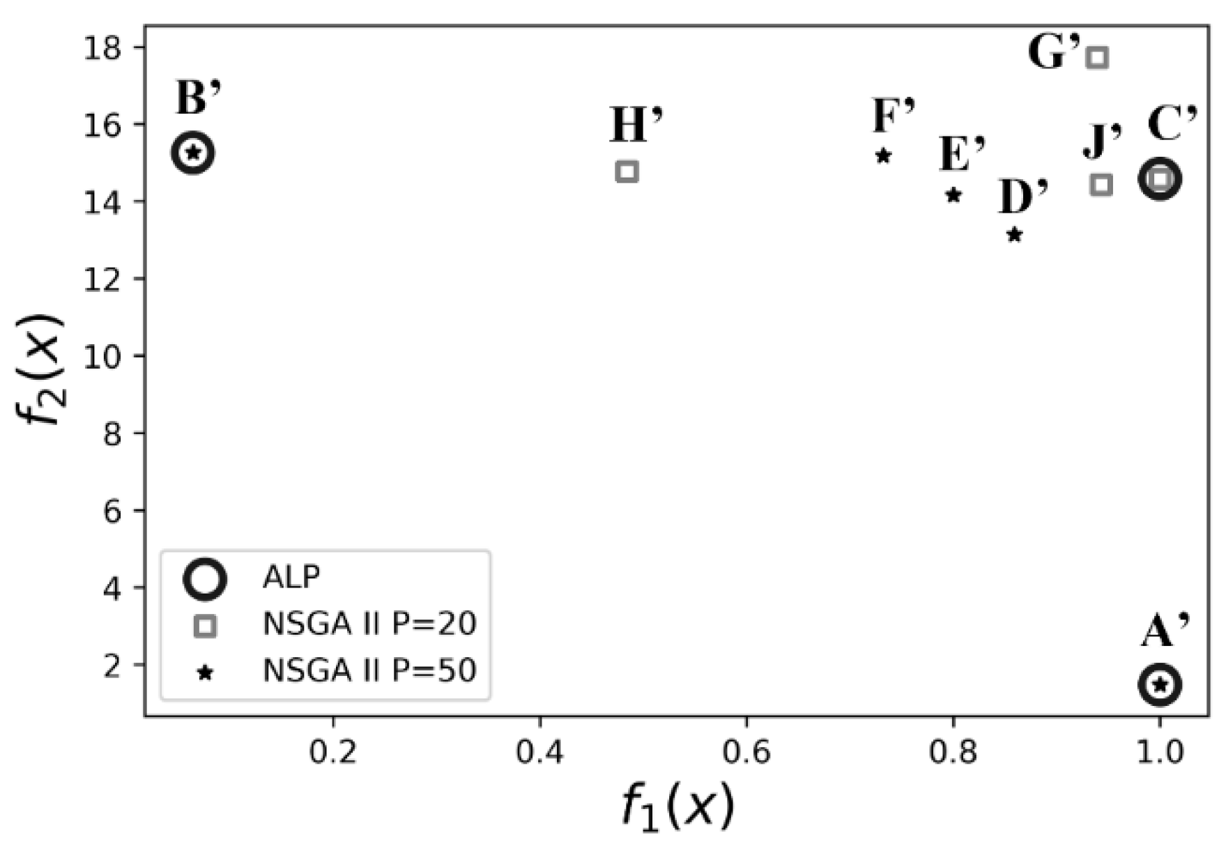
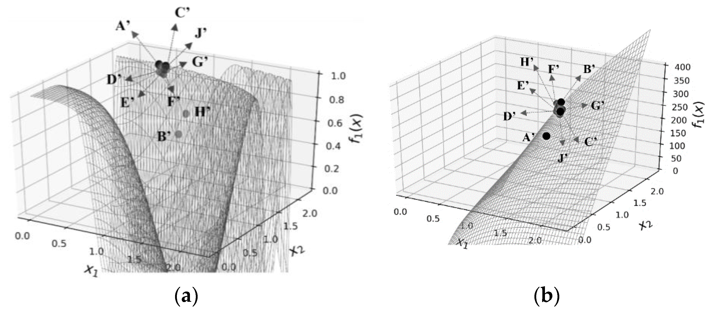
Through applying the three chosen optimizing methods, the satisficing method, and the verification method, NSGA II, we obtain the results and summarize them in Table 4. Since there are two objectives (goals), we use different weights to combine them linearly, so we show the results for each weight. We also use different starting points for the solution searching to show whether a solution algorithm is sensitive to the starting point. We visualize the solutions in objective space and x-f(x) space in Figure 2 and Figure 3. The three optimization algorithms cannot return any feasible solutions. Due to the difference in the scale of the two objectives, one cannot use optimizing algorithms to solve the example problem by linearly combining them, because (i) the objective with a large scale dominates the other objective(s) and (ii) a linearized function of the weighted sum objective in a local area can be singular.
For a multi-objective (multi-goal) problem with nonconvex functions, when the scale of the objectives varies largely, optimizing algorithms cannot return feasible solutions, whereas a satisficing strategy may allow designers to identify adequate solutions. This is explained using the KKT conditions hereafter.
When using optimizing algorithms to solve optimization problems, the first-order derivative of the Lagrange equation with respect to decision variable x, which is a function of the parameters P of the model (the coefficients in objectives and constraints), decision variables x (if any objective or constraint is nonlinear), Lagrange multipliers μ and λ, and weights 𝓅 , combining the multiple goals, is shown in Equation (1).
x L x , μ , λ = y P , x , μ , λ ,   𝓅
For a satisficing strategy, the first-order derivative of the Lagrange equation contains only the coefficients of the deviation variables in the objective, since only deviation variables d constitute the objective (not the decision variables, x). For a κ -goal cDSP with m inequality constraints g(x) and equality constraints h(x), if we use weights to combine the κ goals G(x,d), i.e., using the Archimedean strategy to manage a multi-goal cDSP, then the coefficients in the first-order Lagrange equation are only the weights and τ τ is the Lagrange multiplier of the goal functions; see Equation (2).
d L x s , d , μ , λ , τ = d z d + i = 1 m μ i d g i x s j = 1 λ j d h j x s k = 1 κ τ k d G x s , d = y 𝓅 , τ
when using optimization, the second-order Lagrange equation may still have parameters and decision variables due to nonlinearity; see Equation (3). For satisficing, the second-order Lagrange equation with respect to deviation variables degenerates to zero because the objective of a cDSP is a linear combination of deviation variables; see Equation (4). That is why satisficing solutions do not need to meet the second-order KKT conditions.
xx 2 L x , μ , λ = x y P , x , μ , λ , 𝓅 = y P , x
dd 2 L x s , d , μ , λ , τ = d y 𝓅 , τ 0
Although both optimal solutions x * and satisficing solutions x s meet the first-order KKT conditions, the chance of maintaining the first-order KKT conditions for the two strategies under uncertainties varies. If any uncertainty with probability P takes place to an item ℑ in the first-order equation that destroys its equilibrium, we denote it as Pr ˜ | P . For an N-dimension, Q-parameter (here, we define a coefficient or an intercept of a constraint or an objective as a parameter. A parameter has a given value (either a constant value or a stochastic value) and the value does not depend on any decision variables), and κ -goal problem, using optimizing strategy, the source of ˜ can be decision variables x n ˜ , Lagrange multipliers μ i ˜ and λ j ˜ , and weights 𝓅 k ˜ ; for satisficing strategy, the source of ˜ can only be the weights 𝓅 k ˜ and the Lagrange multipliers for the goals τ k ˜ . If and only if none of the items under the uncertainty breaks the equilibrium of the first-order equation, then the optimal/satisficing solution is still optimal/satisficing under this uncertainty. For an N-dimension, Q-parameter, and κ -goal problem, the probabilities of maintaining an optimal solution and a satisficing solution under Uncertainty P are given in Equations (5) and (6), respectively.
Pr x * | P q = 1 Q 1 Pr P q ˜ | P n = 1 N 1 Pr x n ˜ | P i = 1 m 1 Pr ( μ i ˜ | P ) j = 1 1   Pr ( λ j ˜ | P ) k = 1 κ 1 Pr ( 𝓅 k ˜ | P )
Pr ( x s | P ) k = 1 κ 1 Pr ( 𝓅 k ˜ | P ) k = 1 κ 1 Pr ( τ k ˜ | P )
As the value of any probability is in the range of [0, 1], the more items on the right-hand side we multiply (the more items the probability depends on), the lower the probability becomes. The items in Equation (6) are fewer than those of Equation (5). Hence, the chance of maintaining an optimal solution under Uncertainty P is often smaller than the chance of maintaining a satisficing solution with the same uncertainty; Equation (7).
Pr x * | P Pr x s | P
In summary, using the satisficing strategy, we are less likely to lose a solution due to uncertainty for nonconvex problems with multiple objectives that have various scales; see Equations (8) and (9). Using satisficing, designers can deal with nonconvex, multi-objective problems that may be incomplete or inaccurate and with uncertainties, which helps remove Assumptions 1 and 2.
Pr S | Nonconvexity objectives   with   various   scales Satisficing
Pr S | Nonconvexity objectives   with   various   scales Optimizing
Pr x s | P Satisficing Pr x * | P Optimizing

1.4. A Limitation in the ALP to Be Improved

Just like NSGA II, the ALP also has a parameter, the reduced move coefficient, or RMC, that may impact the solution space, especially for multi-goal problems. The problems as simple as the example problem in Section 1.3 is not sensitive to RMC setting, but more complicated problems are. We use a test problem of steel rod manufacturing to illustrate it in Section 4.
The RMC is a fractional step size [6] defining the starting point for the next iteration. In the ALP, the RMC has been set at 0.5 as a default value. In fact, in the ALP, a designer has no knowledge of the connection between the RMC and solution quality or the opportunity for improving solution efficiency by controlling the RMC. Improving the RMC determination is discussed in [30]. In this paper, we give more explanations about the motivation, the advantages of the satisficing strategy using the cDSP and ALP, and the benefits of parameter learning.
We introduce the ALP and discuss the limitation of using a fixed RMC in Section 2. In Section 3, we introduce parameter learning to make the RMC adaptive for each iteration. In Section 4, we use a test problem that is sensitive to the RMC value—the steel hot rod-rolling process—to demonstrate efficacy of the augmented ALP, that is, the adaptive linear programming algorithm with parameter learning (ALPPL). In Section 5, we summarize the contributions and comment on the generalization of parameter learning for use in gradient-based optimization methods.

2. How Does the ALP Work?

2.1. The Adaptive Linear Programming (ALP) Algorithm

The ALP algorithm is implemented in DSIDES. DSIDES is used to formulate and solve engineering design problems, and it is especially efficient in dealing with nonlinear problems [6]. In DSIDES, the nonlinear problem is formulated as a compromise decision support problem (cDSP). Then, the ALP is invoked to solve the nonlinear problem. The nonlinear problem is linearized in a synthesis cycle. The resulting linear problem is solved using the revised dual simplex algorithm. The synthesis cycle is repeated until the solution satisfies a set of stopping criteria or is terminated after a fixed number of iterations.
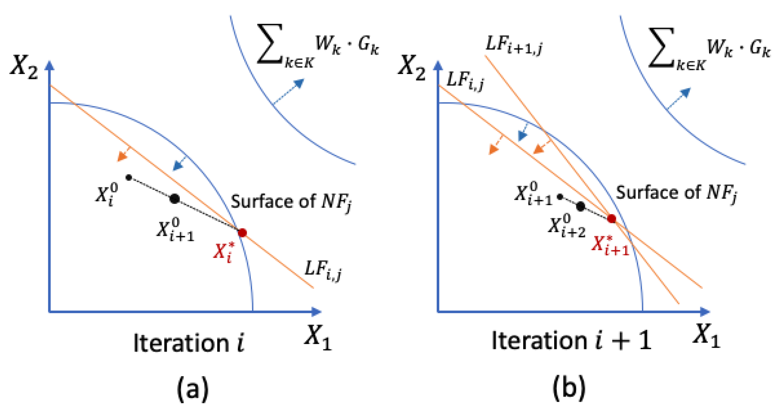
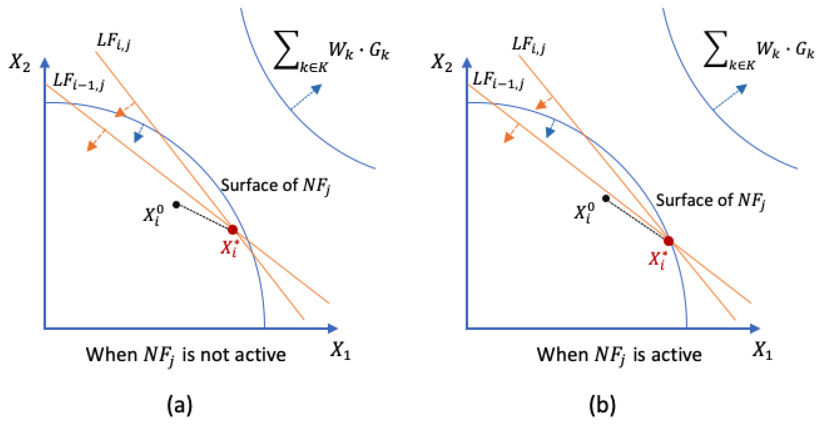
The ALP incorporates a local approximation algorithm [6,31], in which a secant plane of the paraboloid (with the second-order derivatives at the starting point as the coefficients) replaces the original nonlinear function. In Figure 4, we show two dimensions of a problem being approximated in two iterations (synthesis cycle). The weighted sum of the goals is k K W k · G k . The starting point X 0 0 may not be in the feasible region. A random search or a Hooke–Jeeves pattern search can be invoked to identify a point X 1 0 in the feasible area. In the ith first iteration, the problem is linearized at X 1 0 .
In iteration i, Figure 4a, a projection of a nonlinear constraint NFj onto a two-dimensional plane, X1-X2, is approximated at X i 0 , so an approximated constraint LFi,j is obtained. Doing this for all nonlinear functions and framing a linear model, the revised simplex dual algorithm is used to obtain solution X i * . Using the RMC heuristic, we find the starting point of the next iteration X i + 1 0 . In iteration i + 1, Figure 4b, the approximated linear constraints of both iterations LFi,j and LFi+1,j are accumulated, and a solution X i + 1 * is returned and the starting point of iteration i + 2 is again defined using the RMC, X i + 1 0 and X i + 1 * .
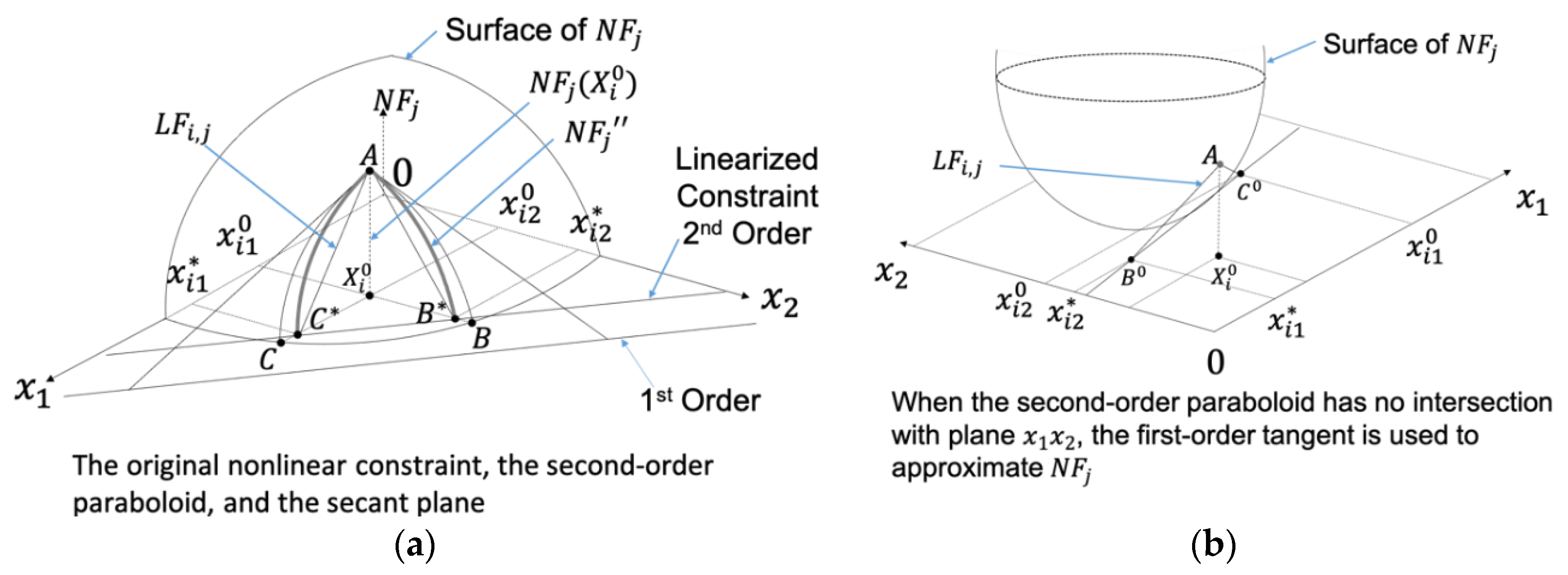
In Figure 5a, we illustrate the two-step linear approximation method. First, NFj (Paraboloid ABC) is approximated to NFi,j″ (Paraboloid AB*C*) with the diagonal terms of its Hessian matrix at X i 0 as coefficients. Then, NFj″ is approximated to a secant Plane LFi,j (Plane AB*C*). NFj″ and LFi,j are computed as follows.
NFi,j″ is obtained using the second-order full derivatives at X i 0 , Equation (10), because the second-order partial derivatives have limited impact on the gradient.
NF i , j = NF j X i 0 + p = 1 n x ip x ip 0 NF j x ip 0 + 1 2 p = 1 n x ip x ip 0 2 2 NF j x ip 2 0
From Equation (10), for the pth dimension, the quadratic to be solved to obtain x ip x ip 0 is:
NF j X i 0 + x ip x ip 0 NF j x ip 0 + 1 2 x ip x ip 0 2 2 NF j x ip 2 0 = 0
If Equation (11) has real roots, Figure 5a, by solving Equation (11) and selecting the root between Equations (12) and (13) with the smaller absolute value for each dimension, we obtain the intersection that is closer to the paraboloid in each dimension, such as B* and C*.
NF j x ip 0 * = NF j X i 0 2 NF j x ip 2 0 NF j x ip 0 NF j x ip 0 2 2 NF j X i 0 2 NF j x ip 2 0
NF j x ip 0 * = NF j X i 0 2 NF j x ip 2 0 NF j x ip 0 + NF j x ip 0 2 2 NF j X i 0 2 NF j x ip 2 0
If Equation (11) has no real roots, Figure 5b, NFi does not intersect Plane x, then the first-order derivative at X i 0 is used, Equation (14).
NF j x ip 0 * = NF j x ip 0
Based on the intersections in each dimension, such as B* and C*, we obtain LFi.
LF i , j = p = 1 n x ip NF j x ip 0 * p = 1 n x ip 0 NF j x ip 0 * NF j X i 0
Algorithm 1 summarizes the constraint accumulation algorithm. If the degree of convexity of NFj is positive or slightly negative (greater than −0.015) at the starting point of the ith iteration, and if the constraint is active in the (i − 1)th iteration, that is, X i 1 * is on the surface of NF j , then the accumulated constraints replace NF j , Equation (16); otherwise, the single linear constraint in the ith iteration is NF j .
Algorithm 1. Constraint Accumulation Algorithm
In the ith iteration,
for every j in J
    if    1 n p = 1 n 2 NF j x ip 2 0.015
      and NF j X i 1 * = 0
LFi,j, = LFi-1,j ∪ LFi,j
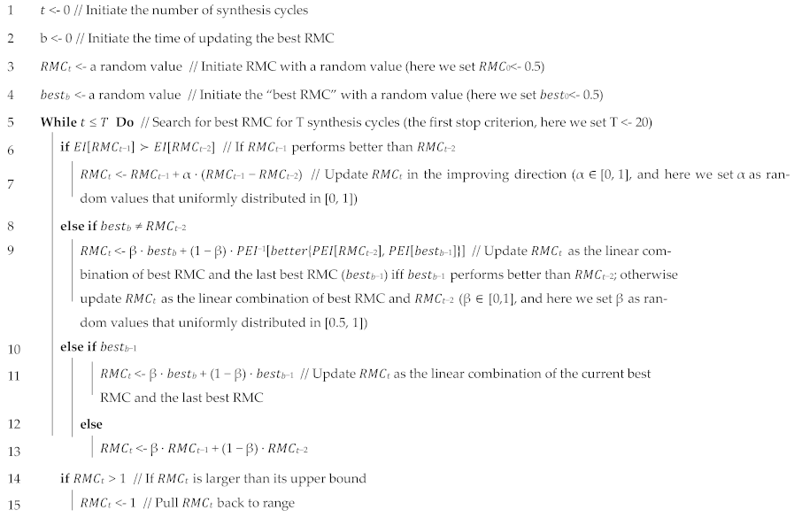
Then, the revised simplex dual algorithm is invoked to solve the linear problem P i L , so a solution X i * is obtained. A point X i + 1 0 , between the starting point X i 0 and the solution X i * , becomes the starting point of the next iteration. The RMC is used to determine X i + 1 0 , Equation (17).
X i + 1 0 =   X i 0 +   RMC   · X i *   X i 0

2.2. The Reduced Move Coefficient

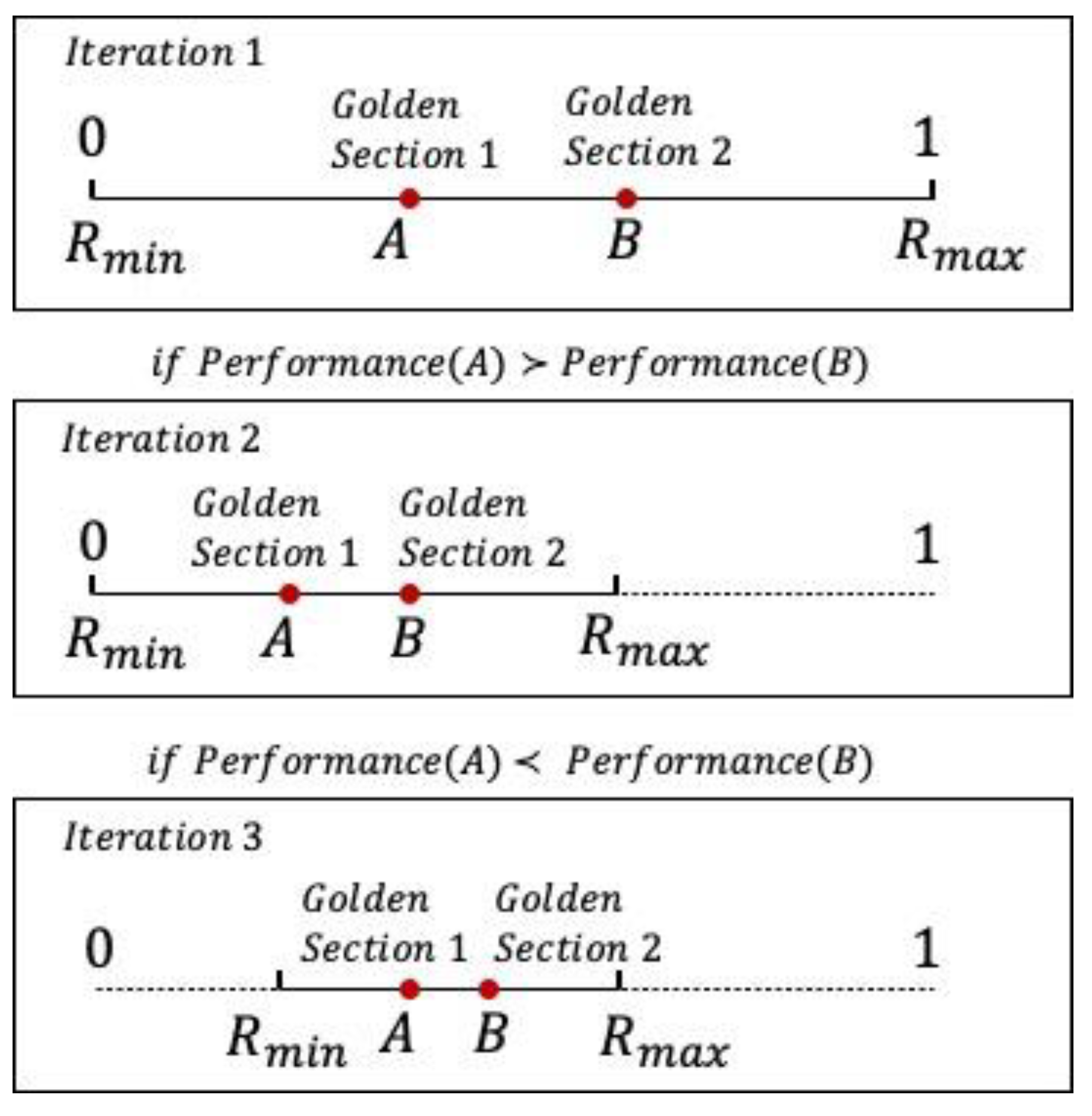
The RMC is in the range [0, 1] and it defaults to 0.5 based on experimental observations [6], but 0.5 may not be the best for every problem. An optional golden section search algorithm is added to progressively narrow the range of the RMC by cutting off the sub-range with large deviations or larger violations of the constraints until the range is too small to reduce, Figure 6. The golden section search algorithm is given as follows – visualized in Figure 6 and summarized a Algorithm 2.
Algorithm 2. Golden section search for updating the RMC
#Define Performance function using RMC to linearize the model and obtain the merit function value
FUNCTION Performance (Model, RMC)
Linearize Model using ALP with RMC into Linear_Model
Solve Linear_Model using Dual Simplex
RETURN Z

#Define Golden Section Search function
FUNCTION GoldenSectionSearchForRMC (Rmin, Rmax, Th):
RMCa = Rmin + (0.382)*(Rmax − Rmin)
RMCb = Rmin + (1 − 0.382)*(Rmax − Rmin)
WHILE (RMCb − RMCa > Th):
  #Compare the performance of using RMCa versus RMCb
IF Performance (Original_Model, RMCa) < Performance (Original_Model, RMCb):
RMC = RMCa
Rmax = RMCb
ELSE:
RMC = RMCb
Rmin = RMCa
RETURN RMC

#Initialize parameters
Rmin = 0
Rmax = 1
Th = 0.0001

#Call the Golden Section Search Function
GoldenSectionSearchForRMC (Rmin, Rmax, Th)
With the golden section search approach, the desired sub-range of the RMC may be missed if the performance oscillates in the range of the RMC. The criterion to evaluate the approximation performance is oversimplified—the deviations and the constraint violations. Given these limitations, in this paper, we propose to use parameter learning to determine the relation between the RMC value and solution quality with more evaluation criteria. Machine learning techniques are used to improve algorithms [32,33], so we leverage this idea to improve the ALP.
We hypothesize that by incorporating parameter learning in the ALP, we can update the RMC based on richer performance criteria. There are three steps to verify this hypothesis. In Section 3, we propose ALPPL to realize the three steps.
  • Step 1. Identifying the criteria—to evaluate approximation performance.
  • Step 2. Developing evaluation indices (EIs)—to quantify the approximation performance with RMC values.
  • Step 3. Learning the desired range of each EI (DEI)—to tune the RMC.
In the next section, we discuss how parameter learning is used to dynamically change the value of the RMC.

3. Parameter Learning to Dynamically Change the RMC

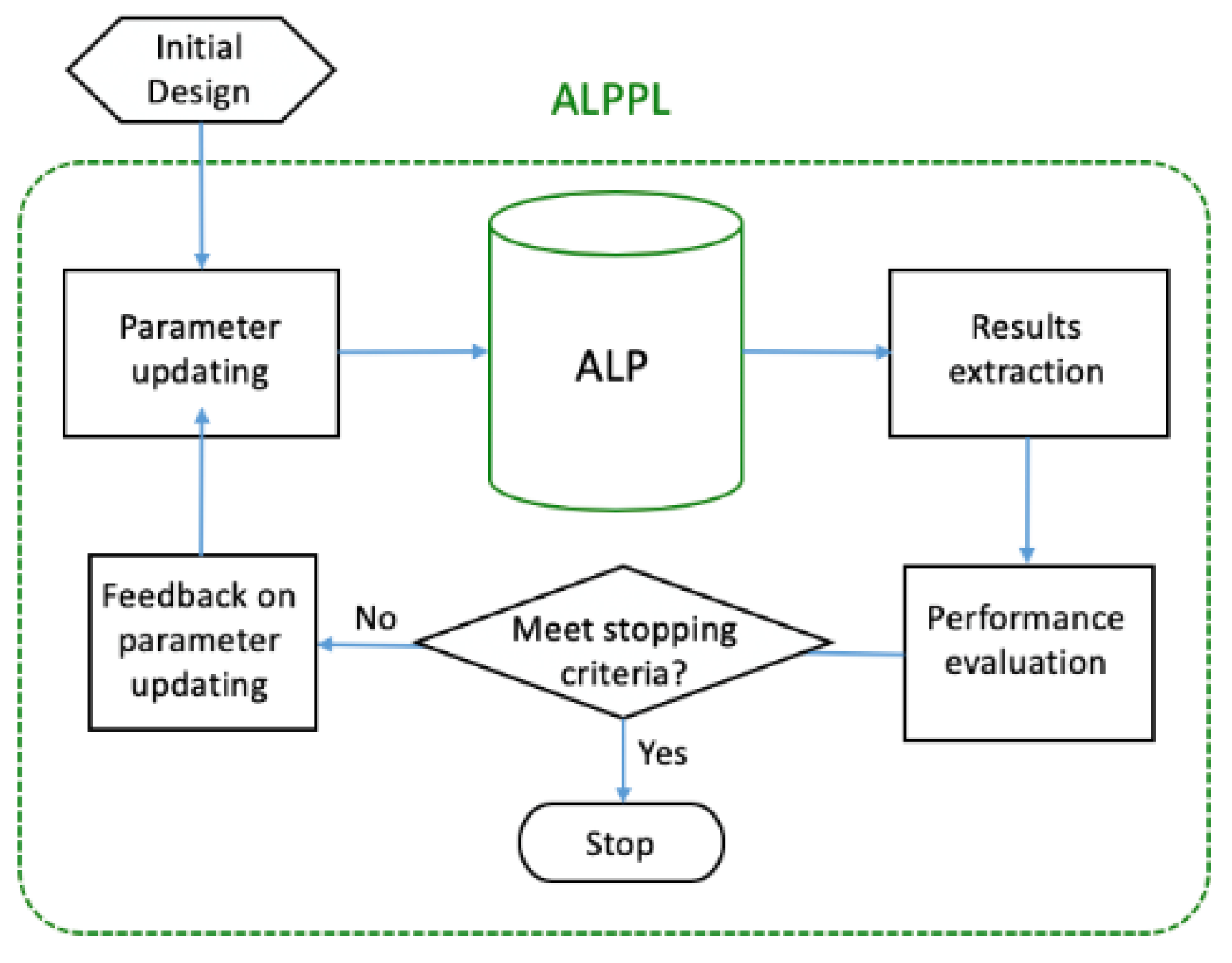
In this section, the adaptive linear programming algorithm with parameter learning (ALPPL) is proposed, Figure 7. We add parameter updating, results extraction, performance evaluation, and feedback on parameter updating to the ALP.

3.1. Step 1—Identifying the Criteria

In ALPPL, we add more criteria to the two criteria considered in the golden section search—deviation and constraint violation. We use a list, EIs[best], to record all the evaluation indices.
  • Criterion 1—deviation.
The deviation in every iteration is recorded and ranked among all iterations. The best deviation in all iterations is stored in EIs[best]. Through implementing multiple design scenarios (lexicographic and/or weight scenarios), we obtain the deviations for all scenarios and iterations, and the desired range DEI is updated accordingly.
  • Criterion 2—robustness of solutions.
We extend the notion of “feasibility” to “robustness”, which means the solutions should be feasible under multiple design scenarios and relatively insensitive to model errors and uncertainties. We assume errors and uncertainties result in changes in the boundary of the feasible region. The nonlinear surface is a part of the boundary. Therefore, the robustness of the solution can be measured by how far it is away from the nonlinear surface. In Figure 8, we show two situations. The arrows indicate the direction of the feasible space bounded by the inequality constraints while minimizing the deviation. In Figure 8a, the solution x i * is not on the boundary, so it is relatively insensitive to errors and variations of the model, and the nonlinear constraint NFj is not an active constraint. In contrast, in Figure 8b, the solution is on the boundary and NFj is an active constraint. The RMC affects the approximation in the next iteration, so we adjust the RMC to obtain more robust solutions.
  • Criterion 3—approximation accuracy.
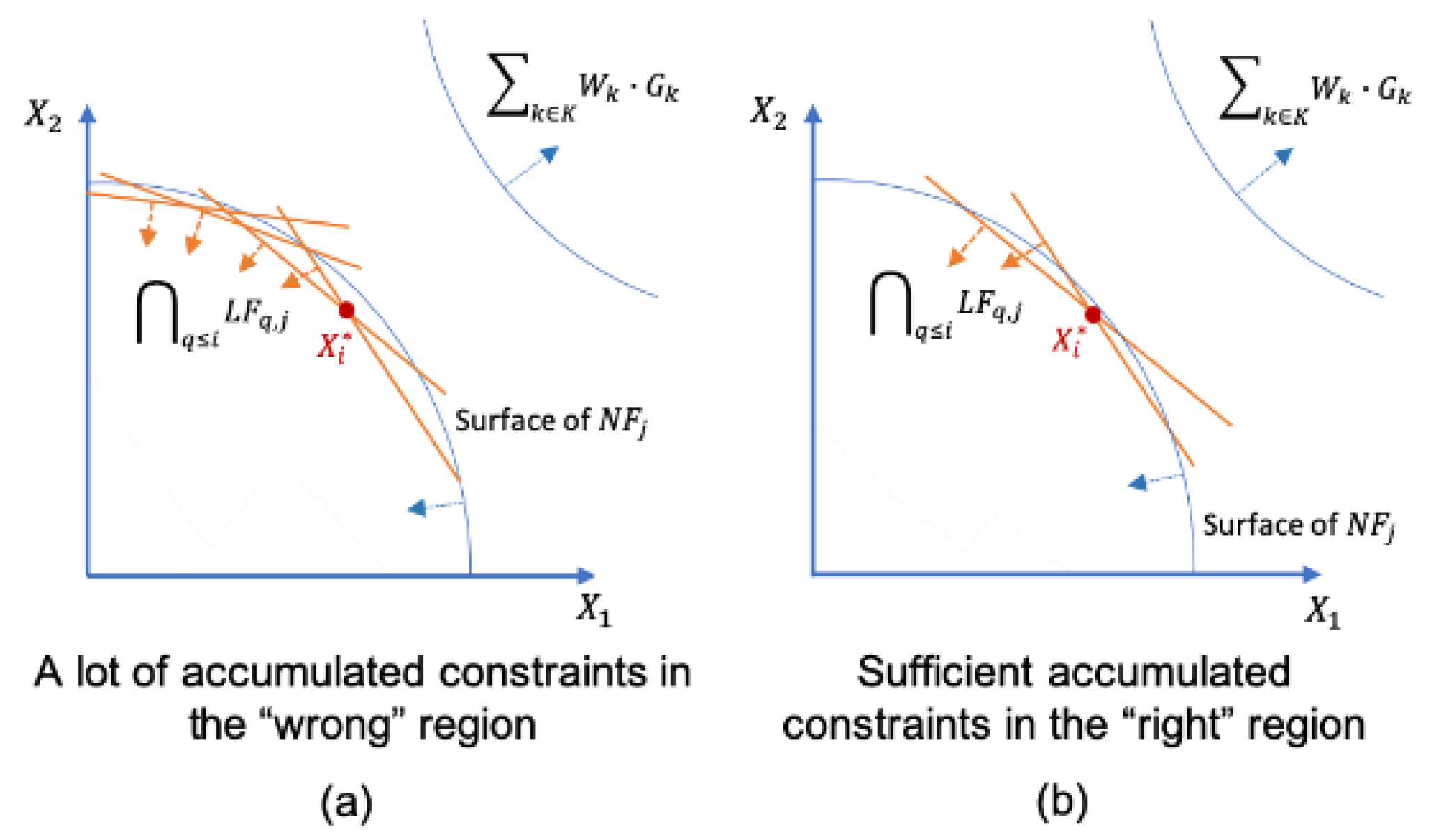
More accumulated constraints may not necessarily lead to a more accurate approximation. We want sufficient and useful accumulated constraints—Figure 9b—rather than many unnecessary accumulated constraints—Figure 9a.
In Table 5, we summarize the criteria for approximation performance evaluation. Based on these criteria, we develop evaluation indices (EIs) in Section 3.2

3.2. Step 2—Developing the Evaluation Indices (EIs)

To manage different design preferences for multiple goals, we obtain solutions using multiple design scenarios. As the design scenarios are discrete and cannot enumerate all situations, we use the limited, discrete solutions to predict a satisficing solution space.
By implementing multiple design scenarios, we acquire the results of the weight-sum deviations, active constraints, accumulated constraints, etc., using which, we develop statistical-based evaluation indices (EIs) as shown in Table 6. Statistical-based quality control has been used to monitor model profiles [34], so we leverage the statistics to obtain EIs.
Our development of the EIs is based on the index for the robust concept exploration method, error margin index (EMI) [31], and design capability index (DCI) [35]. This is based on the central limit theorem that the results as samplings of each criterion follow Gaussian distributions, and the sampling statistics represent their characteristics. Therefore, we use the mean (μ) and the standard deviation (σ) as EIs and tune the RMC by minimizing the μ and σ of each EI.
Index for evaluating the weight-sum deviation—μZ and σZ. To maintain the goal fulfillment (one minus weight-sum deviation) relatively insensitive to design scenario changes, we control the center and spread of the sample solutions by minimizing μZ and σZ.
Index for evaluating the robustness—μNab, σNab, μNaoc, and σNaoc. Using the simplex algorithm, we obtain the vertex solution to the approximated linear problem. At a vertex solution, there is at least one active constraint (AOC) or active bound (AB) of the approximated linear problem, but we prefer fewer AOCs and ABs so the chance of losing a solution due to potential errors or variations is relatively small, so we minimize the μNab, σNab, μNaoc, and σNaoc.
Index for evaluating the computational complexity—μNacc, σNacc, μNit, and σNit. As the approximation accuracy is not necessarily improved by increasing the number of accumulated constraints (Nacc) or the number of approximation iterations (Nit), we need to find the ranges of Nacc and Nit associated with good weight-sum deviations and robustness. We desire Nacc and Nit to be acceptable under all design scenarios and be insensitive to scenarios changing, so we measure μNacc, σNacc, μNit, and σNit and identify their appropriate ranges.
In summary, we tune the RMC by satisfying the EIs—μNab, σNab, mNaoc, σNaoc, μNacc, σNacc, μNit, and σNit— to obtain desired ranges (DEI). Then, the RMC tuning becomes: “given” the parameters and variables, “find” the value of decision variables that can “satisfy” constraints and bounds and “minimize” an objective. Here, we rank the EIs in the ith iteration among all iterations and choose the first κ items with minimum values. These are the most important κ where EIs attain their best and most stable performance. Algorithm 3 is a summary of the RMC parameter learning algorithm.
Algorithm 3. #Define Parameter-learning function
FUNCTION ParameterLearning(Model, Design scenarios, RMC, EIs, κ, I):
WHILE i < I:
IF RMC[i-1] = RMC_best:
    RMC[i] = average(RMC[i-2], RMC_best)
ELSE:
    RMC[i] = average(RMC[i-1], RMC_best)
FOR N Design Scenarios:
    Linearize Model using ALP with RMC[i] into Linear_Model
    Solve Linear_Model using Dual Simplex
RETURN EIs[i]

FOR j in Range(0, i):
    Rank EIs[i][j] from minimum to maximum
    DEI = EIs[i][round(κ*i)]

IF (number of EIs[i] ∈ DEI for all Design scenarios) >
(number of EIs[Cycle of RMC_best] ∈ DEI for all Design scenarios):
    RMC_best = RMC[i]

RETURN RMC_best

#Initialize parameters
Model = Original_Model
Design scenarios = N weight scenarios
RMC [0] = 0.5
EIs = [μZ, σZ, μNab, σNab, μNaoc, σNaoc, μNacc, σNacc, μNit, σNit]
Z, Nab, Naoc, Nacc, Nit = 0
DEI = [0, 0, 0, 0, 0, 0, 0, 0, 0, 0]
κ = 0.6
I = 50

#Call Parameter-Learning function
FUNCTION ParameterLearning(Model, Design scenarios, RMC, EIs, κ, I)

3.3. Step 3—Learning the DEI to Tune the RMC

We identify the desired range of the EIs (DEI), learn the connections between the RMC and the EIs, and bring the EIs into the DEI by setting the RMC. To make the process efficient, we combine off-line learning and the on-line learning. First, we use off-line learning using a sample of RMC values to initialize the DEI and parameters and then adopt on-line learning to update the DEI and tune the RMC. In Figure 10, we illustrate the two processes (Rectangles B and C) and show their relationship with the synthesis cycle A.
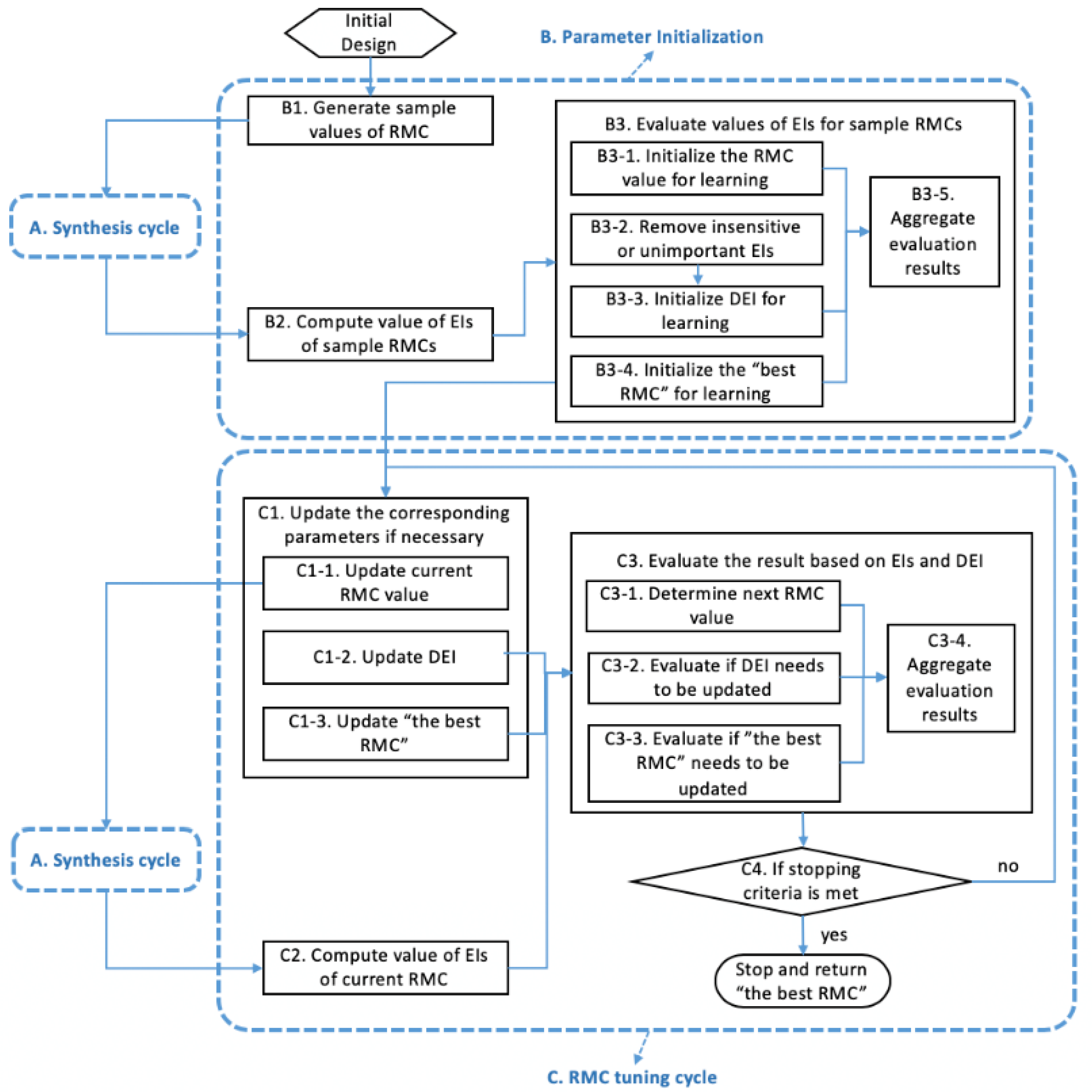
During parameter initialization (B), we generate sample values of RMC (B1). By running the synthesis cycle (A) with each RMC value, we obtain the corresponding EIs (B2) and evaluate them (B3). We choose the RMC value associated with the best EIs as the starting RMC value for tuning (B3-1) and remove the EIs that are insensitive to RMC changes (B3-2). We initialize the DEI based on the sample results (B3-3) to allow a certain proportion (e.g., 75%) of RMC values to fall into the DEI. We choose the best RMC among the sample (B3-4) to start the on-line learning. These results (B3-1 to B3-4) are aggregated as the “actions to be taken” (B3-5) and the input of the RMC tuning cycle (C).
For the RMC tuning cycle (C), with an RMC value (C1-1), we run the synthesis cycle (A) and obtain the results (C2). By evaluating the results using the DEI and comparing with previous iterations (C3), we determine the next RMC value (C3-1), update the DEI if necessary—either restrict or relax the DEI based on the tradeoffs among EIs (C3-2)—and update the best RMC if necessary (C3-3). These evaluation results are aggregated (C3-4) for judging whether to stop iterating (C4)—the program either goes to the next iteration of RMC tuning with the aggregated results (C3-4) as input or stops with the best RMC as the returned value. The stopping criteria include the number of total iterations and the number of iterations without updating the best RMC. This part is summarized as Algorithm 4.
Algorithm 4. The RMC parameter-learning algorithm
1 Given: the best RMC sample value, updating rules
2 Initialize: t = 0, best = the best RMC sample value, RMC0 = the best RMC sample value, the maximum iteration number T, stopping criterion 2 = {best has not been updated in n iterations}
3 While t = do T // Define stopping criterion 1
4   RMCt = Next_RMC
5    Run synthesis cycle

4. A Test Problem

In this section, we apply ALPPL to an industry-inspired problem, the integrated design of a hot-rolling process chain for the production of a steel rod [36]. It is a nonlinear problem, and the RMC value has a significant impact on the result.

4.1. The Hot Rod-Rolling Process Chain

Hot rod rolling is a multi-stage manufacturing process in which a reheated billet, slab, or bloom produced after the casting process is further thermo-mechanically processed by passing it through a series of rollers [36]. During the thermo-mechanical processing, there is an evolution of microstructure of the material, in this case, steel. Columnar grains in the cast material are broken down to equiaxed grains. Along with the evolution of grain size, there is a phase transformation of the steel. The phase transformation is predominant during the cooling stage that follows the hot rod-rolling process chain. The transformation of the austenite phase of steel to other phases like ferrite, pearlite, or martensite takes place during this stage. The final microstructure of the material after the rolling and cooling process defines the mechanical properties of the product.
Many plant trials are required to produce a new steel grade with improved properties and performance. These trials are usually expensive and time-consuming. Hence, there is a need to address the problem from a simulation-based design perspective to explore solutions reaching multiple conflicting property/performance goals. The requirement is to produce steel rods with improved mechanical properties such as yield strength (YS), tensile strength (TS), and hardness (HV). These mechanical properties are defined by the microstructure after cooling, which includes the phase fractions (ferrite and pearlite phases are only considered in this problem), pearlite interlamellar spacing, ferrite grain size, and chemical compositions of steel. Nellippallil et al. [36] identify the microstructural requirements after the cooling stage to meet the mechanical properties of the rod. The microstructural requirements are to achieve a high ferrite fraction value, low pearlite interlamellar spacing, and low ferrite grain size values within the defined ranges. The requirement is to carry out the integrated design of the material and the process by managing the cooling rate (cooling process variable), final austenite grain size after rolling (rolling microstructure variable), and the chemical compositions of the material. Hence, we explore the solution space of the defined variables using ALPPL to meet the target values identified for the microstructure after the cooling stage such that the mechanical property requirements of the steel rod are met. Our focus in this paper is to use this example in improving the solution algorithm rather than the design of the material and the manufacturing. The initial design formulation of the problem is shown as follows.
Given
Target values for microstructure after cooling
Ferrite grain size target, Dα,Target = 8 μm
Ferrite fraction target, Xf,Target = 0
Pearlite interlamellar spacing target, S0,Target = 0.15
Find
System variables
X1 cooling rate (CR)
X2 austenite grain size (D)
X3 the carbon concentration ([C])
X4 the manganese concentration after rolling ([Mn])
Deviation variables
d i ,   d i + , i =1,2,3
Satisfy
System constraints
Minimum ferrite grain size constraint          Dα ≥ 8 μm
Maximum ferrite grain size constraint          Dα ≤ 20 μm
Minimum pearlite interlamellar spacing constraint      So ≥ 0.15 μm
Maximum pearlite interlamellar spacing constraint      So ≤ 0.25 μm
Minimum ferrite phase fraction constraint (manage banding)      Xf ≥ 0.5
Maximum ferrite phase fraction constraint (manage banding)  Xf ≤ 0.9
Maximum carbon equivalent constraint    Ceq = (C + Mn)/6;  Ceq ≤ 0.35
Mechanical Property Constraints
Minimum yield strength constraint        YS ≥ 250 MPa
Maximum yield strength constraint        YS ≤ 330 MPa
Minimum tensile strength constraint        TS ≤ 480 MPa
Maximum tensile strength constraint        TS ≥ 625 MPa
Minimum hardness constraint        HV ≥ 130
Maximum hardness constraint        HV ≤ 150
System goals
The target values for system goals are identified in [36] and are listed under the keyword Given above.
Goal   1 :   Achieve   ferrite   grain   size   target   D α Target / D α X i + d 1 + d 1 = 1
Goal   2 :   Achieve   ferrite   fraction   target   X f X i / X f Target + d 2 d 2 + = 1
Goal   3 :   Achieve   pearlite   interlamellar   spacing   target   S o Target / S o X i + d 3 + d 3 = 1
Variable bounds
11 ≤ X1 ≤ 100 (K/min)
30 ≤ X2 ≤ 100 (μm)
0.18 ≤ X3 ≤ 0.3 (%)
0.7 ≤ X4 ≤ 1.5 (%)
Bounds on deviation variables
d i , d i +   0   and   d i d i + = 0   ,   i = 1 , 2 , 3  
Minimize
Minimize the deviation function in the initial design
Z = i = 1 3 W i d i + d i + ;   i = 1 3 W i = 1
There are three goals in the problem—(i) minimize ferrite grain size (Dα), (ii) maximize ferrite Fraction (Xf), and (iii) minimize interlamellar spacing (So). The targets and the acceptable values of the three goals are given. All three goals are nonlinear. There are four design/system variables—cooling rate (CR), final austenite grain size after rolling (D), the carbon concentration ([C]), and the manganese concentration after rolling ([Mn]). We aim to obtain:
  • The range of the system variables to reach the target of each goal of the best RMC for different design preferences and
  • The weight set, W s = k K W k s , that is a compromise of the three goals for different design preferences.
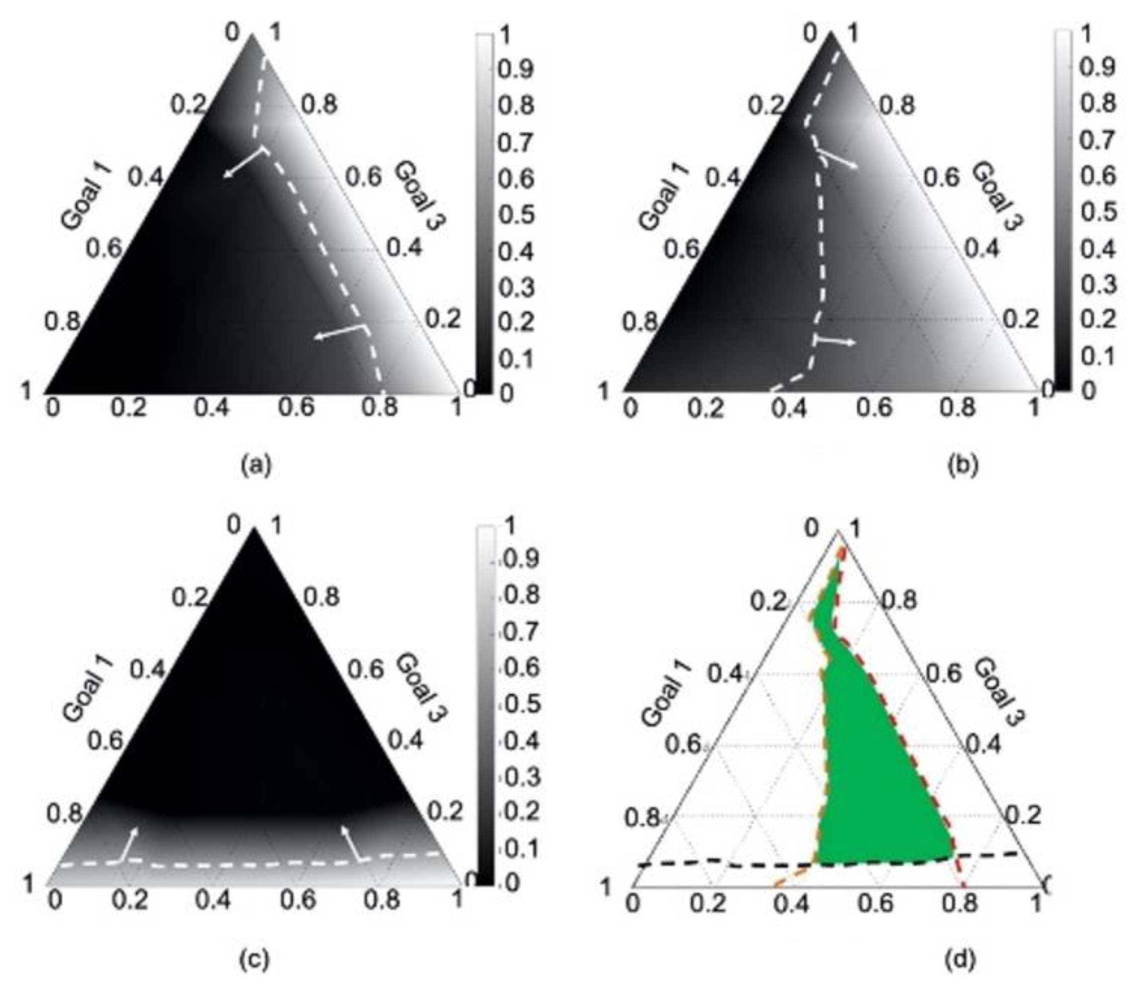
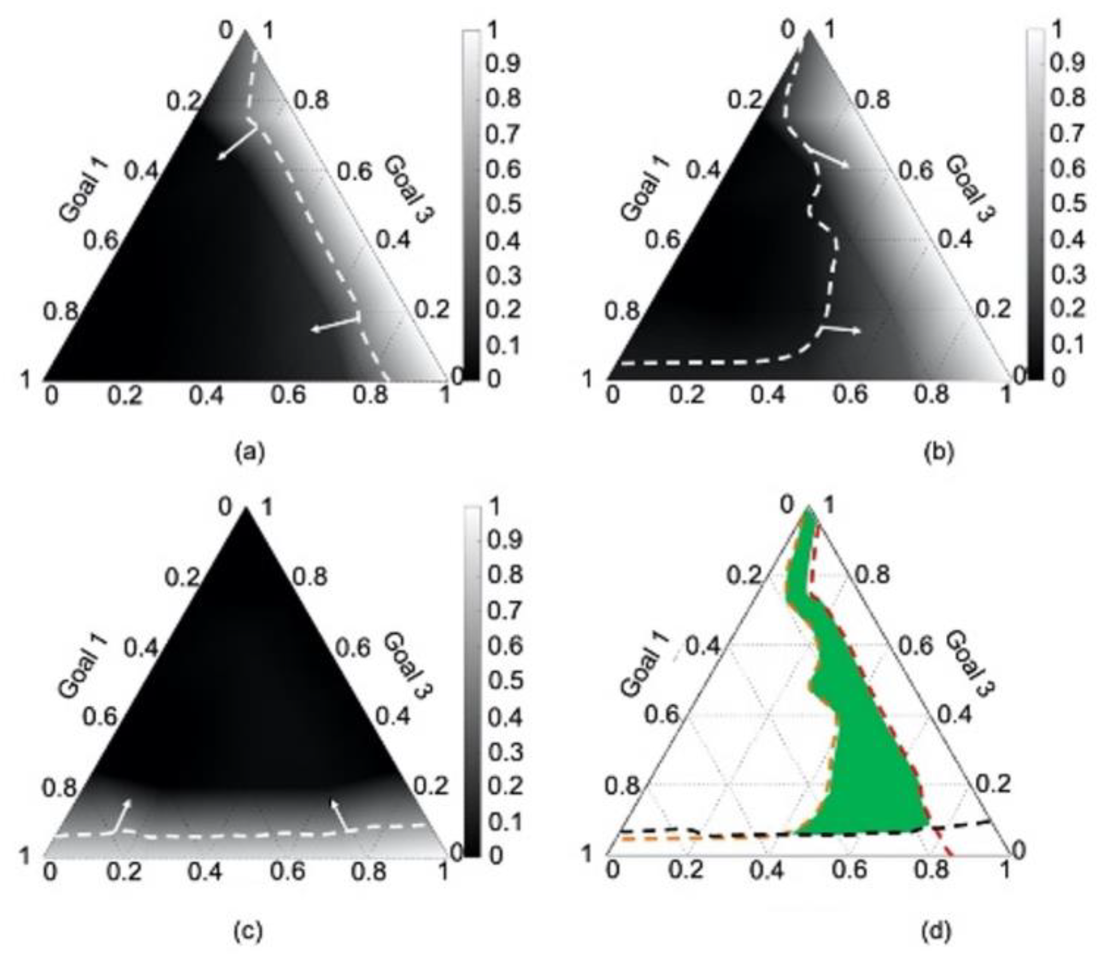
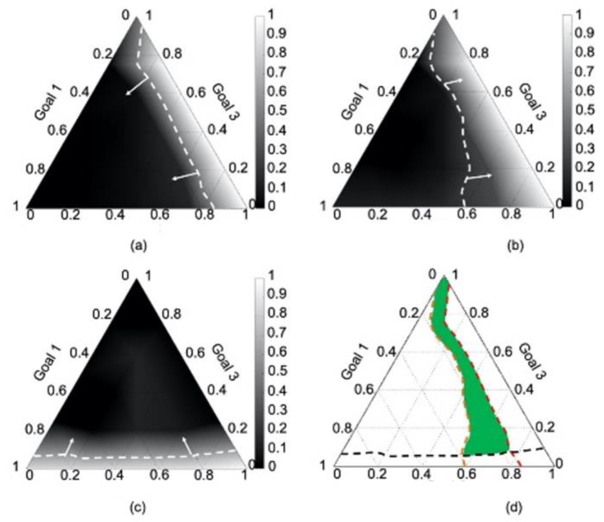
In [36], the authors formulate and execute the initial compromise decision support problem for the hot-rolling process chain problem and carry out a weight sensitivity analysis to identify variable values and the weight set. Ternary plots are generated to visualize and explore the weight set. In each ternary plot, the three axes represent the weights assigned to the three goals, respectively, and the contours indicate the fulfillment of each goal, G k T k , k = 1 ,   2 ,   3 . Since the goals conflict, compromise solutions are desired. Weight sensitivity analysis is a way to mediate compromise around the conflicts among the goals. W 1 s , W 2 s   W 3 s , and W s are the satisficing weight regions identified in the ternary plots, see areas marked using arrows in Figure 11a–d, respectively. To compare G k T k , k = 1 ,   2 ,   3 at the same scale, we normalize the fulfillments of each goal under all weight scenarios in the range [0, 1]. An acceptable fulfillment G k T k of each goal is the dashed line in each ternary plot. The area between the corner (best G k T k ) and the dashed line (acceptable G k T k ) is the satisficing weight area of Goal k , W k s and the superimposed area is the satisficing weight set of all three goals, Ws.
The steps in the RMC tuning algorithm as applied to the hot rod-rolling problem are given in Algorithm A1, Appendix A. In Figure 11d, Figure 12d and Figure 13d, the satisficing weight set Ws when the RMC is 0.1, 0.5, and 0.8 is shown, respectively. When RMC is 0.1, as Figure 11d shows, Ws is large, whereas when RMC is 0.8, as Figure 13d shows, Ws is small. However, using the ALP, there is no mechanism to evaluate which RMC value results in a relatively accurate approximation that gives us a robust Ws. So, we fill this gap using ALPPL.

4.2. Parameter Initialization

There are nineteen weight scenarios used in Table 7, representing a variety of design preferences.
Running Processes B1 and B2 using the sample RMC (0.1, 0.5, and 0.8), we obtain the EIs in Table 8.
Running Process B3, we obtain the initial RMC ( RMC 0 ) and the best RMC as 0.5 (its μ Z and σ Z are bold italic), and we initialize the DEI as shown in Table 9. The results of the parameter initialization—RMC0 (0.5), EIs (Table 5), DEIs (Table 9), and “best” RMC value 0.5—are the input of RMC tuning (C).

4.3. RMC Tuning

We make rules for each procedure of RMC tuning based on heuristics. The heuristics are generalized from parameter learning and can be adjusted through the search process.
C3: Evaluate the result of current RMC based on EIs and DEI.
C3-1: Determine the next RMC value.
Rule 1: Compare the performance of multiple EIs and define the comparison rules. Lines 22–30 in Algorithm A1 in Appendix A are an expansion of this rule. RMC A is better than RMC B because no less than κ of the EI(A) are better than EI(B), whereas other EI(A) do not exceed γ of the upper and lower bound of DEI. In this problem, we set κ = 1/2 and γ = 3 0%.
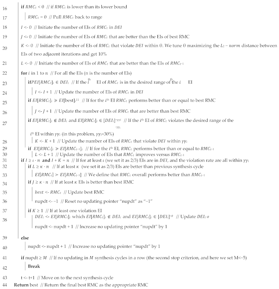
Rule 2: Determine when and how the RMC should be updated. Lines 6–13 in Appendix A explain this rule. We use a hill-climbing approach to update the RMC. If the updating in the previous RMC-tuning cycle improves the performance, then the previous updating is in the “hill-climbing direction,” and we continue updating the RMC in this direction with a step size α; otherwise, we need the best RMC to “pull us back” to the right direction with a portion β; hence, we update the RMC as a linear combination of the best RMC (elite) and the RMC two cycles ago (parent). In this problem, we set α as a random value in [0, 1] and β as a random value in [0.5, 1]. In this way, we incorporate greediness, elitism, and randomness in evolution.
C3-2: Evaluate whether DEI needs to be updated.
Rule 3: Determine when and how the DEI should be updated. See Algorithm A1 in Appendix A, Lines 18–38. In an RMC-tuning cycle, if more than κ EIs are better than the previous cycle, and more than ι EIs are in the DEI, whereas no more than γγ EIs have minor violations, then the DEI is updated. Here, we set κ = ι = 2 / 3 . For a problem with more EIs, κ and ι can be tuned using the performance improvement rate. This rule prevents an over restrictive DEI from blocking us from a better range while ensuring gradual and relatively conservative updating of the DEI.
C3-3: Evaluate whether “the best RMC” needs to be updated.
Rule 4: Determine when and how the best RMC is updated. See Algorithm A1 in Appendix A, Lines 34–36. We use a variable (“best”) to store the best RMC. If more than κ EIs of the current RMC are better than the EIs of the best, the current RMC becomes the new best.
C3-4: We aggregate the results of the RMC tuning RMC t+1, DEI, and best as inputs for the next tuning iteration.
C4: Determine whether to stop iterating.
Rule 5: Make the stopping criteria. To stop RMC tuning at the appropriate time, we use “the maximum number of RMC-tuning iterations” and “the maximum number of RMC-tuning iterations without updating the best RMC” as the stopping criteria.

4.4. Results

Using our test problem, the RMC tuning stops after fourteen iterations. We identify 0.55 as the best RMC for the test problem. Compared with the initial RMC of 0.5, the final best RMC of 0.55 improves σ Z , σ Naoc , and σ Nab . The RMCs and EIs in the fourteen iterations are in Table 10. The DEI is updated four times, and the best RMC is updated three times. The final best RMC is in the ninth iteration.

4.5. Verification and Validation

To verify the efficacy of ALPPL, we evaluate its adequacy and the necessity in returning robust solutions.
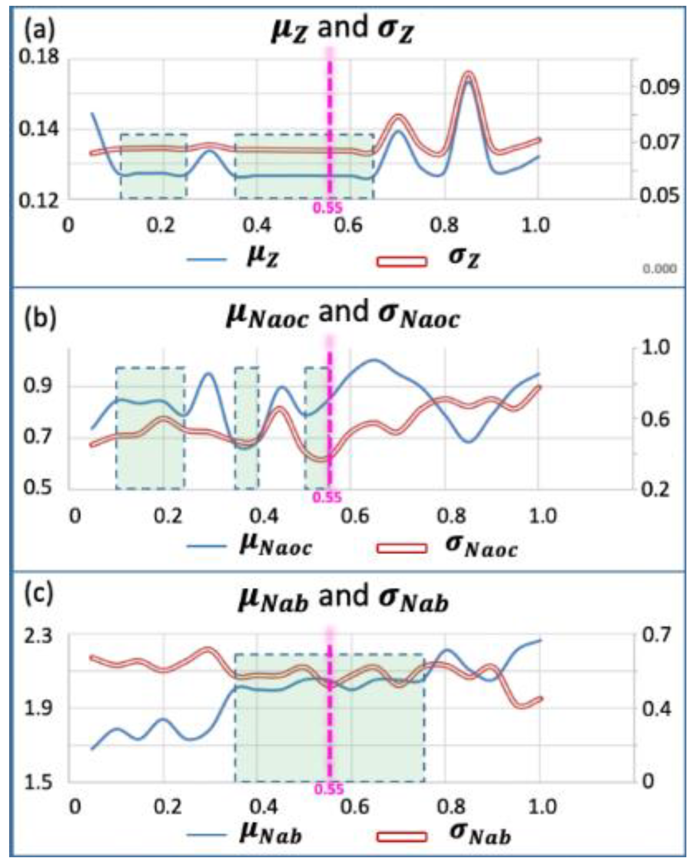
Adequacy—We tested 20 RMC values randomly spread in [0, 1] and identified the relatively insensitive range(s); see Figure 14. If the best RMC returned by the ALPPL falls into the relatively insensitive range(s), then we show that the ALPPL can identify the best RMC. It turns out that the best RMC (0.55) ensures the solutions to fall in a relatively insensitive range. For each pair of EIs (the mean and standard deviation), we identify the range(s) of RMC values, within which, both the mean and the standard deviation have acceptable values and are flat (stable). For example, for the deviation Z, we desire both its mean μz and standard deviation σz to be low values and flat. The two ranges bounded by the dotted rectangles are such ranges. For all EIs, the overlapped desired range is [0.5, 0.55], so this is the relatively insensitive range. The value of 0.55 is in the insensitive RMC range for all EIs, so it is verified that when RMC is 0.55, it gives a relatively robust performance.
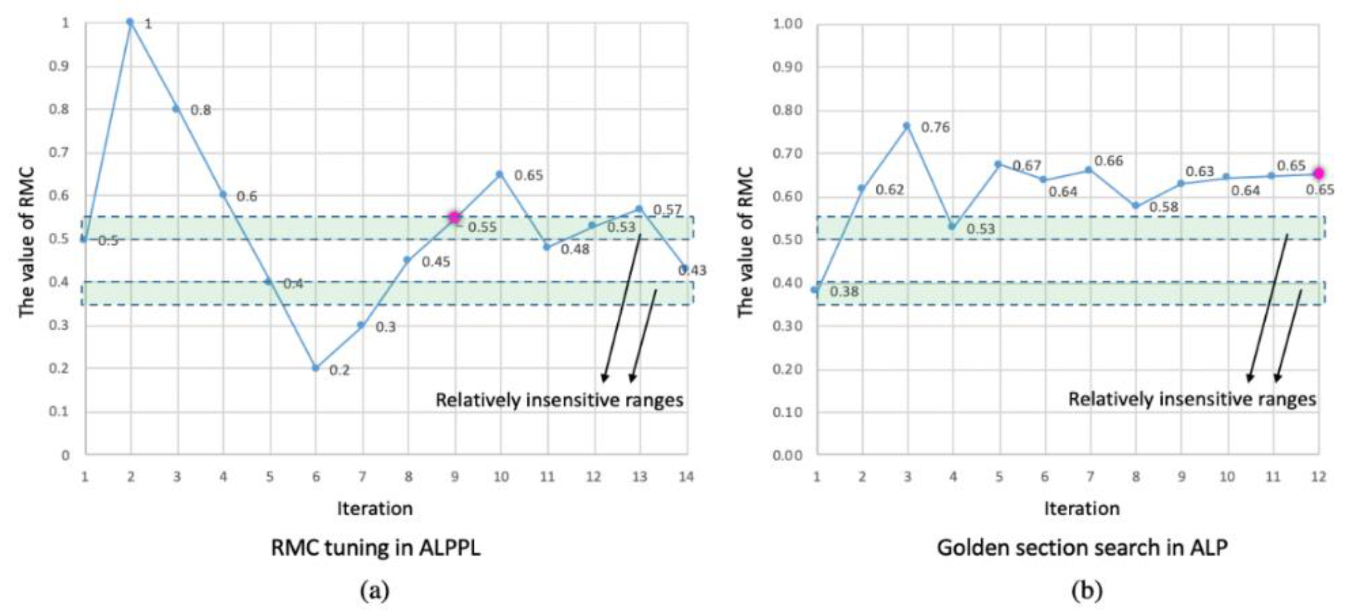
Necessity—The insensitive range is sufficiently explored during the RMC tuning. First, we identify the insensitive range of RMC values—testing 20 RMC values uniformly distributed in [0, 1] with their EIs, we identify two ranges where the solutions are relatively insensitive to scenario changing, [0.35, 0.4] and [0.5, 0.55]. In Figure 15a, we illustrate all fourteen RMC values in RMC tuning. The horizontal axis represents the iteration number and the vertical axis represents the RMC value. Four of the fourteen RMC values fall in the two insensitive ranges, so 28.5% of the tested RMC values fall in the insensitive ranges, whereas the insensitive ranges only occupy 10% of the whole RMC range. Hence, we conclude that our RMC tuning enables a relatively sufficient exploration of the insensitive ranges.
Validation of the improvement of ALPPL versus the ALP. We compare the tested RMC values using parameter learning (ALPPL) in Figure 15a with the tested RMC values using the golden section search (ALP) in Figure 15b. The best RMC identified using the golden section search is 0.65, which is not in the insensitive range; in addition, the RMC values tested in the golden section search are concentrated in [0.57, 0.77], which misses the insensitive ranges [0.35, 0.4] and [0.5, 0.55]. For a solution algorithm that sequentially linearizes the problems in multiple synthesis cycles, the computational complexity is O(n2) [37]—this applies to both the ALP and ALPPL, so the parameter-learning method in this paper does not require much computational power. Other improvements of ALPPL over ALP are summarized in Table 11.

5. Closing Remarks

Our aim in this paper is to improve the determination of one critical parameter in a satisficing method regarding the robustness of the solution and the accuracy of the linearization. We show the benefits of using a satisficing strategy, the cDSP, and ALP to manage engineering design problems, especially when there are multiple goals, nonlinear and nonconvex equations, and the goals have different levels of achievability. However, there is a drawback of the current ALP—one of its parameters, the RMC, has an impact on the linearization and the solution space. For years, the RMC was either user-defined or determined using golden section search. However, there was no mechanism for obtaining insight to improve the approximation by controlling the RMC. The golden section approach may result in missing the sub-range of the RMC with good approximation performance. The best RMC value is sensitive to design scenario changes; only the weighted-sum deviations and feasibility of the solutions are considered when evaluating approximation performance. Hence, to improve the ALP, we incorporate parameter learning into the algorithm and upgrade it to the adaptive linear programming algorithm with parameter learning algorithm (ALPPL). In the ALPPL, we improve the approximation performance in three steps—identifying the criteria for approximation performance, developing evaluation indices (EIs), and tuning the RMC. We use an industry-inspired problem, namely, the hot-rolling process for a steel rod, to demonstrate the improvements of ALPPL (to access DSIDES and ALPPL, please contact the corresponding author. The tutorial for using DSIDES to formulate a cDSP is in this video: https://www.youtube.com/watch?v=tUpVC97Y1L8, accessed on 25 November 2020) over the ALP. The computational complexity of ALPPL is the same as the ALP, which is O(n2).
The parameter-learning method used in this paper can be expanded to other algorithms that apply heuristics to determine the value of parameters. Domain expertise can be helpful in identifying the criteria for performance evaluation and developing evaluation indices. With domain knowledge, the computational complexity of the parameter-learning algorithms can be well controlled within an inexpensive range. This can customize the parameter learning for each algorithm and each problem.
One limitation of this paper is that we did not discuss in great detail the computational complexity of the ALPPL or the parameter learning for algorithm improvement in general, because it can vary for different algorithms or problems. One thing that we can ensure is that, with designers’ domain expertise, by identifying the most critical criteria and then quantifying them as the most representative evaluation indices, the computational power required for the proposed parameter-learning algorithm can be less than that for parameter tuning without domain expertise, since designers can remove the less relevant criteria and insensitive evaluation indices.
In future research, there are several promising directions to explore in the realm of engineering design using the satisficing strategy. Firstly, investigating the applicability and effectiveness of the proposed rule-based parameter-learning procedure across a broader range of engineering problems could provide valuable insights into its generalizability and robustness. Additionally, exploring alternative satisficing algorithms or enhancements to existing algorithms could further improve the efficiency and robustness of design processes. Furthermore, incorporating advanced machine learning techniques, such as reinforcement learning or neural networks, into the satisficing framework may offer new opportunities for adaptive and intelligent decision making in engineering design. Finally, conducting empirical studies and applications in diverse industries and contexts could validate the practical value and benefits of the proposed approach, thereby facilitating its adoption and integration into engineering practice. Overall, these future research directions hold the potential to advance the state of the art in satisficing engineering design and contribute to the development of more automated and robust design methods.

6. Glossary

Accumulated constraint(s): When a nonlinear constraint is concave (the degree of the convexity is lower than −0.015), the approximated linear constraint of the previous iteration is carried forward and combined with its approximated linear constraint in the current iteration. Thus, a concave nonlinear constraint is represented by multiple linear constraints, and those carried forward are called accumulated constraints.
Active constraint: If the slack or surplus of a constraint at a solution point is zero, then it is an active constraint.
Convexity degree: The average value of the diagonal terms of the Hessian matrix of a function. This definition is applied to any paper on the cDSP and ALP.
Deviation: The percentage difference between the value of a goal at a solution and its target.
DSIDES: DSIDES is short for decision support in the design of engineering systems, which is a computational platform for designers to formulate engineering design problems using the compromise decision support problem (cDSP) and linearize and solve the problems using the adaptive linear programming (ALP) algorithm.
Parameter learning: This includes a set of activities to maximize the approximation performance—identifying the evaluation indices (EIs), the desired range of each evaluation index (DEI), and the value of a parameter, namely, the reduced move coefficient (RMC), that makes each EI fall into its desired range, DEI.
Parameter tuning: This means finding the value of a parameter, namely, the reduced move coefficient (RMC), that makes each EI fall into its desired range, DEI. It is a part of parameter learning.

Author Contributions

L.G. was responsible for developing and implementing the advanced adaptive linear programming algorithm with parameter learning and writing this paper with input from her co-authors. F.M. is the originator of the adaptive linear programming (ALP) algorithm. F.M. is responsible for coding the algorithm; see [6]. W.F.S. incorporated the ALP algorithm into the decision support environment, DSIDES. He was instrumental in advising L.G. about the use of DSIDES and ensuring what is written is accurate; see [30]. A.B.N. provided the test example for L.G. to use in her dissertation. He was instrumental in advising L.G. about how the data were structured, the interpretation of the results, and ensuring that what is written is accurate; see [36]. J.K.A. and F.M. mentored L.G.to complete her PhD dissertation. Both supported L.G. financially during her PhD program. Both revised and edited the manuscript. All authors have read and agreed to the published version of the manuscript.

Funding

Lin Guo was supported by the LA Comp Chair and the John and Mary Moore Chair at the University of Oklahoma till August 2021, then is supported by the Pietz Professorship funds and the start-up fund from the Research Affairs Office at South Dakota School of Mines and Technology since September 2021. All the three funding sources are internal.

Data Availability Statement

The data used in this work are taken from the publication by Nellippallil [36].

Acknowledgments

We are grateful to the late O.F. Hughes for originating the adaptive linear programming (ALP) algorithm. We are grateful to H.B. Phouc for coding the ALP algorithm. We are grateful to Krishna Atluri and Zhenjun Ming for their help in testing the ALPPL algorithm. Lin Guo acknowledges the Pietz Professorship funds and the start-up fund from the Research Affairs Office at South Dakota School of Mines and Technology. Farrokh Mistree and Janet K. Allen gratefully acknowledge support from the LA Comp Chair and the John and Mary Moore Chair at the University of Oklahoma.

Conflicts of Interest

On behalf of all authors, the corresponding author states that there is no conflict of interest.

Nomenclature

ALPAdaptive Linear Programming
ALPPLAdaptive Linear Programming with Parameter Learning
cDSP Compromise Decision Support Problem
DEIDesired Range of Evaluation Index
DSPDecision Support Problem
EI/EIsEvaluation Index/Indices
RMCReduced Move Coefficient

Appendix A

The RMC Parameter-Learning Algorithm Customized for the Hot Rolling Process Chain Problem

Appendix A is the RMC parameter-learning algorithm (Algorithm 4) customized for the Cooling Procedure of the Hot Rolling Problem. Appendix A is referenced in Section 4. This algorithm is an extension of the Algorithm 4. More auxiliary parameters are defined to assist parameter learning—T, α, β, γγ, θθ, ι, κ, M. For the parameters that are relatively more important (the results are more sensitive to their values), e.g., θθ, we tune their values. For the parameters that are relatively less important, e.g., ι, κ, M, we set values to them with heuristics.
Algorithm A1. The RMC parameter-learning algorithm (Algorithm 4) customized for the Cooling Procedure of the Hot Rolling Problem
Algorithms 17 00088 i001aAlgorithms 17 00088 i001b
Steps in the RMC-tuning algorithm: Determine the evaluation indices (EIs) based on multiple criteria to classify good results from the bad ones; initialize the desired range of each EI (DEI) of the test problem; identify auxiliary parameters to assist RMC tuning; bring the EIs into DEI by tuning the auxiliary parameters; update DEI to ensure a proportion of good results out of all results; tradeoff between elitism and randomness to ensure a diversity while obtaining rapid convergence.

References

  1. Rios, L.M.; Sahinidis, N.V. Derivative-Free Optimization: A Review of Algorithms and Comparison of Software Implementations. J. Glob. Optim. 2013, 56, 1247–1293. [Google Scholar] [CrossRef]
  2. Vrahatis, M.N.; Kontogiorgos, P.; Papavassilopoulos, G.P. Particle Swarm Optimization for Computing Nash and Stackelberg Equilibria in Energy Markets. SN Oper. Res. Forum 2020, 1, 20. [Google Scholar] [CrossRef]
  3. Behmanesh, E.; Pannek, J. A Comparison between Memetic Algorithm and Genetic Algorithm for an Integrated Logistics Network with Flexible Delivery Path. Oper. Res. Forum 2021, 2, 47. [Google Scholar] [CrossRef]
  4. Viswanathan, J.; Grossmann, I.E. A Combined Penalty Function and Outer-Approximation Method for MINLP Optimization. Comput. Chem. Eng. 1990, 14, 769–782. [Google Scholar] [CrossRef]
  5. Nagadurga, T.; Devarapalli, R.; Knypiński, Ł. Comparison of Meta-Heuristic Optimization Algorithms for Global Maximum Power Point Tracking of Partially Shaded Solar Photovoltaic Systems. Algorithms 2023, 16, 376. [Google Scholar] [CrossRef]
  6. Mistree, F.; Hughes, O.F.; Bras, B. Compromise decision support problem and the adaptive linear programming algorithm. Prog. Astronaut. Aeronaut. Struct. Optim. Status Promise 1993, 150, 251. [Google Scholar]
  7. Teng, Z.; Lu, L. A FEAST algorithm for the linear response eigenvalue problem. Algorithms 2019, 12, 181. [Google Scholar] [CrossRef]
  8. Rao, S.; Mulkay, E. Engineering design optimization using interior-point algorithms. AIAA J. 2000, 38, 2127–2132. [Google Scholar] [CrossRef]
  9. Asghari, M.; Fathollahi-Fard, A.M.; Al-E-Hashem, S.M.; Dulebenets, M.A. Transformation and linearization techniques in optimization: A state-of-the-art survey. Mathematics 2022, 10, 283. [Google Scholar] [CrossRef]
  10. Reich, D.; Green, R.E.; Kircher, M.; Krause, J.; Patterson, N.; Durand, E.Y.; Viola, B.; Briggs, A.W.; Stenzel, U.; Johnson, P.L. Genetic history of an archaic hominin group from Denisova Cave in Siberia. Nature 2010, 468, 1053–1060. [Google Scholar] [CrossRef]
  11. Fishburn, P.C. Utility theory. Manag. Sci. 1968, 14, 335–378. [Google Scholar] [CrossRef]
  12. Nash, J.F., Jr. The bargaining problem. Econom. J. Econom. Soc. 1950, 18, 155–162. [Google Scholar] [CrossRef]
  13. Saaty, T.L. What Is the Analytic Hierarchy Process? Springer: Berlin/Heidelberg, Germany, 1988. [Google Scholar]
  14. Calpine, H.; Golding, A. Some properties of Pareto-optimal choices in decision problems. Omega 1976, 4, 141–147. [Google Scholar] [CrossRef]
  15. Guo, L. Model Evolution for the Realization of Complex Systems. Ph.D. Thesis, University of Oklahoma, Norman, OK, USA, 2021. [Google Scholar]
  16. Speakman, J.; Francois, G. Robust modifier adaptation via worst-case and probabilistic approaches. Ind. Eng. Chem. Res. 2021, 61, 515–529. [Google Scholar] [CrossRef]
  17. Souza, J.C.O.; Oliveira, P.R.; Soubeyran, A. Global convergence of a proximal linearized algorithm for difference of convex functions. Optim. Lett. 2016, 10, 1529–1539. [Google Scholar] [CrossRef]
  18. Su, X.; Yang, X.; Xu, Y. Adaptive parameter learning and neural network control for uncertain permanent magnet linear synchronous motors. J. Frankl. Inst. 2023, 360, 11665–11682. [Google Scholar] [CrossRef]
  19. Courant, R.; Hilbert, D. Methods of Mathematical Physics; Interscience: New York, NY, USA, 1953; Volume 1. [Google Scholar]
  20. Guo, L.; Chen, S. Satisficing Strategy in Engineering Design. J. Mech. Des. 2024, 146, 050801. [Google Scholar] [CrossRef]
  21. Powell, M.J. An Efficient Method for Finding the Minimum of a Function of Several Variables without Calculating Derivatives. Comput. J. 1964, 7, 155–162. [Google Scholar] [CrossRef]
  22. Straeter, T.A. On the Extension of the Davidon-Broyden Class of Rank One, Quasi-Newton Minimization Methods to an Infinite Dimensional Hilbert Space with Applications to Optimal Control Problems; North Carolina State University: Raleigh, NC, USA, 1971. [Google Scholar]
  23. Fletcher, R. Practical Methods of Optimization, 2nd ed.; John Wiley & Sons: Hoboken, NJ, USA, 1987. [Google Scholar]
  24. Khosla, P.; Rubin, S. A Conjugate Gradient Iterative Method. Comput. Fluids 1981, 9, 109–121. [Google Scholar] [CrossRef]
  25. Nash, S.G. Newton-type Minimization via the Lanczos Method. SIAM J. Numer. Anal. 1984, 21, 770–788. [Google Scholar] [CrossRef]
  26. Zhu, C.; Byrd, R.H.; Lu, P.; Nocedal, J. Algorithm 778: L-BFGS-B: Fortran Subroutines for Large-scale Bound-Constrained Optimization. ACM Trans. Math. Softw. (TOMS) 1997, 23, 550–560. [Google Scholar] [CrossRef]
  27. Powell, M. A Tolerant Algorithm for Linearly Constrained Optimization Calculations. Math. Program. 1989, 45, 547–566. [Google Scholar] [CrossRef]
  28. Powell, M.J. A View of Algorithms for Optimization without Derivatives. Math. Today Bull. Inst. Math. Its Appl. 2007, 43, 170–174. [Google Scholar]
  29. Deb, K.; Pratap, A.; Agarwal, S.; Meyarivan, T. A fast and elitist multiobjective genetic algorithm: NSGA-II. IEEE Trans. Evol. Comput. 2002, 6, 182–197. [Google Scholar] [CrossRef]
  30. Guo, L.; Balu Nellippallil, A.; Smith, W.F.; Allen, J.K.; Mistree, F. Adaptive Linear Programming Algorithm with Parameter Learning for Managing Engineering-Design Problems. In Proceedings of the ASME 2020 International Design Engineering Technical Conferences and Computers and Information in Engineering Conference, Online, 17–19 August 2020; American Society of Mechanical Engineers: New York, NY, USA, 2020; p. V11BT11A029. [Google Scholar]
  31. Chen, W.; Allen, J.K.; Tsui, K.-L.; Mistree, F. A Procedure for Robust Design: Minimizing Variations Caused by Noise Factors and Control Factors. J. Mech. Des. 1996, 118, 478–485. [Google Scholar] [CrossRef]
  32. Maniezzo, V.; Zhou, T. Learning Individualized Hyperparameter Settings. Algorithms 2023, 16, 267. [Google Scholar] [CrossRef]
  33. Fianu, S.; Davis, L.B. Heuristic algorithm for nested Markov decision process: Solution quality and computational complexity. Comput. Oper. Res. 2023, 159, 106297. [Google Scholar] [CrossRef]
  34. Sabahno, H.; Amiri, A. New statistical and machine learning based control charts with variable parameters for monitoring generalized linear model profiles. Comput. Ind. Eng. 2023, 184, 109562. [Google Scholar] [CrossRef]
  35. Choi, H.-J.; Austin, R.; Allen, J.K.; McDowell, D.L.; Mistree, F.; Benson, D.J. An Approach for Robust Design of Reactive Power Metal Mixtures based on Non-Deterministic Micro-Scale Shock Simulation. J. Comput. Aided Mater. Des. 2005, 12, 57–85. [Google Scholar] [CrossRef]
  36. Nellippallil, A.B.; Rangaraj, V.; Gautham, B.; Singh, A.K.; Allen, J.K.; Mistree, F. An inverse, decision-based design method for integrated design exploration of materials, products, and manufacturing processes. J. Mech. Des. 2018, 140, 111403. [Google Scholar] [CrossRef]
  37. Sohrabi, S.; Ziarati, K.; Keshtkaran, M. Revised eight-step feasibility checking procedure with linear time complexity for the Dial-a-Ride Problem (DARP). Comput. Oper. Res. 2024, 164, 106530. [Google Scholar] [CrossRef]
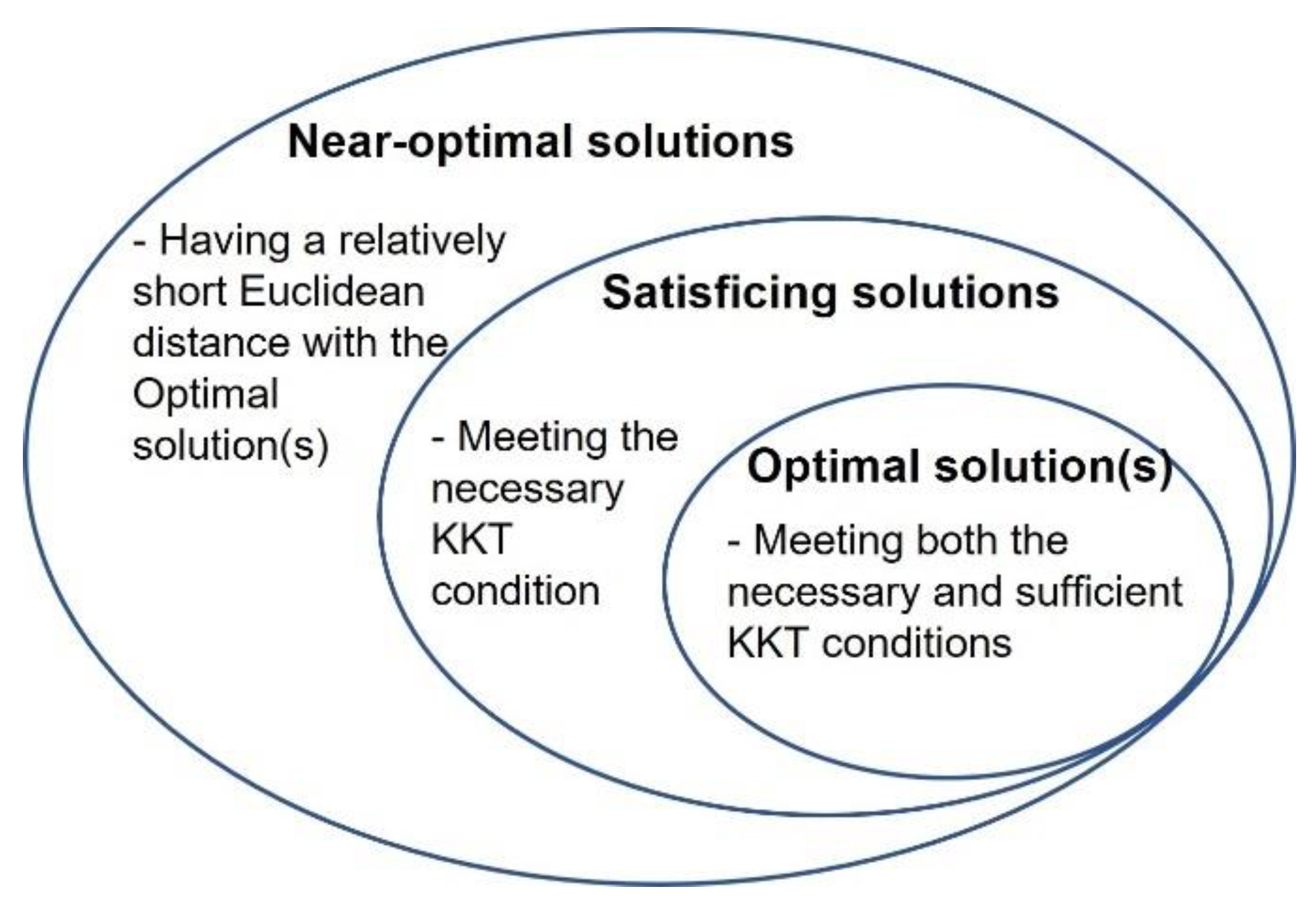
Figure 1. The relationship between the optimal, satisficing, and near-optimal solutions.
Algorithms 17 00088 g001
Figure 2. The solution points to the example problem in objective space using two algorithms—solutions returned by NSGA II are more diverse but sensitive to parameter settings and increasing the population and iterations does not always produce better results.
Algorithms 17 00088 g002
Figure 3. The solution points in the x-f(x) space. Subfigure (a) is the x-f1(x) space and Subfigure (b) is the x-f2(x) space. All solutions’ f1(x) values are close to 1.0 except B’ and H’; all solutions’ f2(x) values are close to 400 except A’ [15].
Algorithms 17 00088 g003
Figure 4. The approximation and solution using ALP in two iterations when RMC = 0.4. Subfigure (a) is Iteration i and Subfigure (b) is Iteration i + 1.
Algorithms 17 00088 g004
Figure 5. The two-step linear approximation methods using the ALP. Subfigure (a) illustrates the situation when the second-order paraboloid of the riginal nonlinear constraint NFj has intersection with Plane x1x2, whereas Subfigure (b) illustrates the situation when the second-order paraboloid has no intersection with Plane x1x2 hence the first-order tangent is used to approximate NFj.
Algorithms 17 00088 g005
Figure 6. The golden section search for the RMCs in the ALP.
Algorithms 17 00088 g006
Figure 7. The concept of adaptive linear programming algorithm with parameter learning (ALPPL).
Algorithms 17 00088 g007
Figure 8. A relatively sensitive solution and a robust solution. Subfigure (a) shows the situation when the solution x i * is not on the boundary - the surface of NFj, whereas Subfigure (b) shows the situation when the solution x i * is on the boundary.
Algorithms 17 00088 g008
Figure 9. Unnecessary accumulated constraints versus necessary accumulated constraints. Subfigure (a) illustrates the situation when the accumulated constraints are in the “wrong” region, which results from the linearization points in multiple iterations being in a region that gives poor achieved values of the goal. Subfigure (b) illustrates the opposite situation – when the accumulated constraints are in the “right” region.
Algorithms 17 00088 g009
Figure 10. ALPPL including parameter initialization and RMC tuning.
Algorithms 17 00088 g010
Figure 11. The satisficing weight set when setting RMC = 0.1. Subfigure (ac) show the acceptable regions of weights for the three goals, respectively. Subfigure (d) shows the acceptable region weights for all three goals. The dashed lines demarcate acceptable regions for the goals and the arrows indicate the direction of acceptability.
Algorithms 17 00088 g011
Figure 12. The satisficing weight set when setting RMC = 0.5. Subfigure (ac) show the acceptable regions of weights for the three goals, respectively. Subfigure (d) shows the acceptable region weights for all three goals. The dashed lines demarcate acceptable regions for the goals and the arrows indicate the direction of acceptability.
Algorithms 17 00088 g012
Figure 13. The satisficing weight set when setting RMC = 0.8. Subfigure (ac) show the acceptable regions of weights for the three goals, respectively. Subfigure (d) shows the acceptable region weights for all three goals. The dashed lines demarcate acceptable regions for the goals and the arrows indicate the direction of acceptability.
Algorithms 17 00088 g013
Figure 14. Identifying the insensitive range of RMC value using twenty RMC values. Subfigure (ac) show the insensitive ranges of the mean and standard deviation of Z, Naoc, and Nab, respectively.
Algorithms 17 00088 g014
Figure 15. The comparison of ALPPL and ALP regarding RMC updating. Subfigure (a) illustrates the best RMC of the fourteen iterations when applying ALPPL. Subfigure (b) illustrates the best RMC of the twelve iterations when applying ALP.
Algorithms 17 00088 g015
Table 1. The mechanisms in the cDSP and ALP to find satisficing solutions [16].
MechanismsAdvantageAssumption Removed
Using goals and minimizing deviation variables instead of objectivesAt a solution point, only the necessary KKT condition is met, whereas the sufficient KKT condition does not have to be met.
Therefore, designers have a greater chance of finding a solution and a lower chance of losing a solution due to parameterizable and/or unparameterizable uncertainties.
Assumption 1
Using second-order sequential linearizationDesigners can have a balance between linearization accuracy and computational complexity.Assumption 2
Using accumulated linearizationDesigners can manage nonconvex problems and deal with highly convex, nonlinear problems relatively more accurately.Assumption 2
Combining interior-point search and vertex searchDesigners can avoid getting trapped in local optima to some extent and identify satisficing solutions which are relatively insensitive when the starting points change.Assumption 1
Allowing some violations of soft requirements, such as the bounds of deviation variablesDesigners can manage rigid requirements and soft requirements in different ways to ensure feasibility.
As a result, goals and constraints with different scales can be managed.
Assumptions 1 and 2
Table 2. The optimization model and compromise DSP of the example.
OptimizingSatisficing
Objective Functions
f 1 x = cos ( x 1 2 + x 2 3 )
f 2 x = 25 · x 1 2 3 + 50 · x 2 2 3 + 50 · x 1 · x 2 2
Constraints and Bounds
s . t .   x 1 · x 2 1 f 1 x 0 f 2 x 0 0 x 1 2 0 x 2 2
Combination of Objective Functions
Max   i = 1 2 w i · f i x
Given
x 1 ,   x 2 ,   d 1 ± ,   d 2 ±
f 1 x = cos x 1 2 + x 2 3
f 2 x = 25 · x 1 2 3 + 50 · x 2 2 3 + 50 · x 1 · x 2 2
Find
x 1 ,   x 2 ,   d 1 , d 2
Satisfy
Goals:
f 1 x 1.2 + d 1 d 1 + = 1
f 2 x 400 + d 2 d 2 + = 1
Constraints:
x 1 · x 2 1
f 1 x 0
f 2 x 0
d i · d i + = 0 , i = 1 ,   2
Bounds:
0 x 1 ,   x 2 2
0 d 1 ± ,   d 2 ± 1
Minimize
Merit   function   Z = i = 1 2 w i · d i + d i +
Table 3. Methods for comparison of the two strategies.
StrategyOptimizingSatisficing
Item
Model formulation constructMathematical programming
Goal programming
Compromise decision support problem
Solution algorithmConstrained optimization by linear approximation (COBYLA) algorithmAdaptive linear programing (ALP) algorithm
Trust-region constrained (trust-constr) algorithm
Sequential least squares programming (SLSQP) algorithm
Nondominated sorting generation algorithm II/III (NSGA II)
SolverPython SciPy.optimizeDSIDES [6]
Table 4. Solutions to the example problem—dominated solutions for each weight are in italics; for each method, the best solution of each design scenario is marked using a capital letter (A’, B’, C’, D’, E’, F’, G’, H’, and J’) [15].
WeightStarting PointCOBYLATrust-ConstrSLSQPALPNSGA II/III—Population (P) = 20/50
Solution i = 1 2 wi · fi(x)Solution i = 1 2 wi · fi(x)Solution i = 1 2 wi · fi(x)Solution i = 1 2 wi · fi(x)Solution i = 1 2 wi · fi(x)
(1, 0)(0.5, 1)Cannot manage nonconvex equations with boundsAll solutions violate one or more constraintsAll solutions violate one or more constraintsA’ (0.51,1.82)1P = 20:
G’ (0.55, 1.85)
P = 50:
A’ (0.51, 1.82)
P = 20:
0.99
P = 50:
1
(0, 0)
(2, 0.5)
(0, 1)(0.5, 1)B’ (0.51, 1.96)15.27P = 20:
H’ (0.52, 1.92)
P = 50:
B’ (0.51, 1.96)
P = 20:
14.86
P = 50:
15.36
(0, 0)
(2, 0.5)
(0.5, 0.5)(0.5, 1)C’ (0.55, 1.82)7.5P = 20:
H’ (0.52, 1.92)
P = 50:
D’ (0.53, 1.87)
P = 20:
7.69
P = 50:
7.78
(0, 0)
(2, 0.5)
(0.7, 0.3)(0.5, 1)C’ (0.55, 1.82)4.9P = 20:
C’ (0.55, 1.82)
P = 50:
E’ (0.53, 1.88)
P = 20:
4.9
P = 50:
5.01
(0, 0)
(2, 0.5)
(0.3, 0.7)(0.5, 1)C’ (0.55, 1.82)10.01P = 20:
J’ (0.54, 1.85)
P = 50:
F’ (0.53, 1.89)
P = 20:
10.49
P = 50:
10.6
(0, 0)
(2, 0.5)
Table 5. Criteria for the evaluation of approximation performance.
CriteriaMeaning and Representation
Weight-sum deviationsThe unfulfilled percentage of the goals compared with their targets
RobustnessWhether a solution is away from the boundary of the system as defined by the nonlinear model
Approximation accuracyWhether the nonlinear constraints are approximated well by a set of linear constraints in the sub-region that contains the solutions that fulfill the goals to an extent
Table 6. Develop evaluation indices (EIs)—mean (μ) and standard deviation (SD) (σ).
CriteriaInformationEIsMeaning
Weight-sum deviation Z = k K W k · d k + d k + μzThe average weight-sum deviations
σzThe stability of the weight-sum deviations when changing design scenarios
RobustnessThe number of active bounds: μNabThe average sensitivity of the solutions under all design scenarios to variable bounds
σNabThe stability of the sensitivity of the solutions to variable bounds when changing design scenarios
The number of active original constraints: μNaocThe average sensitivity of the solutions under all design scenarios to original constraints
σNaocThe stability of the sensitivity of the solutions to original constraints when changing design scenarios
Approximation accuracyThe number of accumulated constraints: μNaccThe average complexity of the approximated problem under all design scenarios
σNaccThe stability of the complexity of the approximated problem when changing design scenarios
The number of iterations: μNitThe average convergence speed under all design scenarios
σNiThe stability of the convergence speed when changing design scenarios
Table 7. Weight vectors used in [36] as different design scenarios.
W1W2W3 W1W2W3
11001100.750.25
20101200.250.75
3001130.330.330.33
40.50.50140.20.20.6
50.500.5150.40.20.4
600.50.5160.20.40.4
70.250.750170.60.20.2
80.2500.75180.40.40.2
90.7500.25190.20.60.2
100.750.250
Table 8. Results of EIs using sample RMC values with nineteen design scenarios.
RMCStatisticsZNitNaccNabNaoc
0.1μ0.148046.5818.741.790.84
σ0.06795.950.870.630.50
0.5μ0.146720.4219.472.050.79
σ0.06759.470.840.620.42
0.8μ0.14808.3214.162.210.79
σ0.06755.566.940.630.71
Table 9. The initial DEIs.
DEI of μzDEI of σzDEI of μNaocDEI of σNaocDEI of μNabDEI of σNab
[0, 0.1477][0, 0.0677][0, 0.82][0, 0.55][0, 1.95][0, 0.63]
Table 10. The EIs, DEI, RMC, best RMC of the fourteen iterations of RMC tuning.
IterationRMCWeight-Sum DeviationNumber of Active Original ConstraintsNumber of Active BoundsBetter Than Cycle (t-1)Better Than Best RMCUpdate DEI
μzσzμNaocσNaocμNabσNab
10.50.1470.0680.790.422.050.62--[1, 1.95]
->
[1, 2.05]
21.00.1520.0710.950.782.260.45NN-
30.80.1480.0680.790.712.210.63NN-
40.60.1470.0670.950.522.000.58YY->
50.40.1470.0680.680.482.000.58YY-
60.20.1470.0680.840.601.840.60NN->
70.30.1540.0690.950.521.790.71NN-
80.450.1470.0680.890.662.000.58YN-
90.550.1470.0670.840.372.050.52YY-
100.650.1470.0671.000.582.050.62NN->
110.480.1470.0680.890.662.050.62NN-
120.530.1470.0670.840.692.000.58YN-
130.570.1470.0670.840.372.110.57NN-
140.430.1450.0690.840.602.000.58NN-
Table 11. ALPPL with RMS tuning versus ALP with golden section search.
ALPPLALP
General comparisonSearch methodRule-based parameter learningGolden section search
Criteria used for evaluation of the RMCDeviation (fulfillment of the goals), the robustness of the solutionFulfillment of the goals
If the approximation is sensitive to the scenario changingConsidering different scenarios, the most appropriate RMC is identified. The approximation is relatively insensitive to scenario changesIn each scenario, the best RMC is identified; it may vary as the scenario changes. The approximation is relatively sensitive to scenario changes
Stopping criteriaThe best RMC has not been updated for n iterations, or the total iteration number reaches a thresholdThe distance between two golden section points is less than a threshold ε
ComplexityO(n2)O(n2)
Comparison of the cooling problem resultsNumber of search iterations1412
If the identified best RMC is in the insensitive rangeYesNo
Number of tested RMC values falling into insensitive range42
Is the insensitive range explored sufficientlyRelatively sufficientlyInsufficiently
Disclaimer/Publisher’s Note: The statements, opinions and data contained in all publications are solely those of the individual author(s) and contributor(s) and not of MDPI and/or the editor(s). MDPI and/or the editor(s) disclaim responsibility for any injury to people or property resulting from any ideas, methods, instructions or products referred to in the content.