Article

Performance-Constraint Fault Tolerant Control to Aircraft in Presence of Actuator Deviation

1
AVIC Chengdu Aircraft Industrial (Group) Co., Ltd., Chengdu 610091, China
2
School of Aeronautics and Astronautics, University of Electronic Science and Technology of China, Chengdu 610071, China
*
Author to whom correspondence should be addressed.
Algorithms 2024, 17(5), 196; https://doi.org/10.3390/a17050196
Submission received: 9 March 2024 / Revised: 23 April 2024 / Accepted: 4 May 2024 / Published: 7 May 2024

Abstract

:
Accuracy of electro-mechanical actuator in aircraft is susceptible to variable operation conditions such as electromagnetic interference, changeable temperature or loss of maintenance, leading in turn to flight performance degradation. This paper proposed an unified control paradigm that aims to keep aircraft’s velocity in a safe boundary and shorten the system stabilizing time in presence of actuator deviation. The controller is derived following a practical finite-time-convergence (FTC) with extended dynamics, and an integrated state-constraint structure so as to restrict air vehicle’s attitude rate or translation velocity. It is proved that the system state converges to a sphere near the origin in a finite time, the state trajectory is always remain within the prescribed range, and all signals of the closed-loop system are uniformly ultimately bounded. Compared simulation with the quadratic Lyapunov-based FTC method and an asymptotic convergence controller are conducted on an unmanned helicopter prototype. Results show that the proposed controller enhances the dynamic and fault-tolerant performance of resisting actuator fluctuation.

1. Introduction

The control-stability of aircraft depends on actuator operating condition, its stable output is the prerequisite to achieve reliable flight, high speed flight vehicles are particularly sensitive to actuator performance. Accuracy of electro-mechanical or hydraulic actuators is easily deteriorated in complex flight environment such as electromagnetic interference, low temperature or leakage. In this situation, a fault-tolerant control is expected to accommodate actuator deviation within a certain range [1]. Research works of dealing with actuator failure are presented in a variety of ways, for instance, the model prediction control [2], multi-variable integral terminal sliding mode control [3], incremental nonlinear FTC [4], and intelligent methods [5,6]. Estimation and compensation to system failures are the key thoughts in active FTC strategy. Guan [7] developed an intelligent fault diagnosis approach and corresponding disturbance compensation control for hypersonic vehicles. One primary problem is that a high convergence speed of fault estimation module will amplify the noisy signal, further, Ref. [8] proposed an output-feedback fault-tolerance method for the non-affine actuator faults, thus input nonlinearity of system is considered. Zhang [9] reconstructed the unmatched actuator faults in sliding-mode control scheme, which can keep a rapid convergence speed to some certain faults. An online dynamics reconstruction scheme is established for more broader actuator failure based on adaptive observer [10]. Gerardo [11] developed a quasi linear-parameter-varying observer to achieve fault detection and isolation for the quad-rotor vehicles. Other studies such as the faults estimators [12,13] and fuzzy nonlinear observer [14] are also very effective. The main characteristic of estimation and compensation frame lies in an additional system module, and its stability depends on carefully parameters selection. Therefore, direct FTC methods have also been paid attention.
Yan [15] designed a robust FTC framework by introducing back-stepping control technique in unmanned helicopters. Linear parameter varying (LPV) methodology [16] showed the robust performance to aileron and rudder loss-of-efficiency faults, based on it, a virtual actuators was reconfigured to mitigate fault effects [17]. Generally, adaptive control schemes are often designed together with a recurrent neural networks [18], linear quadratic regulator [19], dynamic control allocation [20] in active fault-tolerant control. It is worth noting that there needs a trade-off between robustness of close-loop system and convergence speed in direct FTC schemes. Obviously, the rapid stabilizing ability is one of the goals even failure occurs, especially for the inner-loop attitude dynamics in aircraft, thereby finite-time-convergence theory on the autonomous systems is often introduced into the attitude controller [21,22]. Compared with the exponential convergence methods, it has faster convergence rate while usually along with a large instantaneous output. Meanwhile, Flight manage system needs to limit the kinematic speed of air vehicle once the capability fade of actuators to ensure states are always in the safe boundary to a flawed system, it is deemed to be a regulation problem of nonlinear system together with state restriction. The barrier-Lyapunov function is an effective analysis tool [23,24,25] to this kind of issue, it has applied to different rigid body objects including the quadrotor [26], underwater vehicle [27], and hypersonic aerocraft [28]. The main contribution in this paper lies in unifying the practical FTC approach and barrier-Lyapunov tool into a new control paradigm, then establishing a finite-time-convergence fault-tolerant (FTC-FT) controller, and it has an adaptive mechanism to balance the robustness and dynamic capability for a flawed system.
Works are arranged as follows, we firstly build the FTC-FT method for a class of strict-feedback multiple-input and multiple-output (MIMO) system in Section 2, the stability and convergence time of closed-loop system signals are analyzed strictly in Section 3. Next, the proposed paradigm is applied to channels of the strong coupling yaw and vertical motion of unmanned helicopter considering actuator oscillation. In Section 5, its effectiveness and superiority are validated by compared simulation with the quadratic Lyapunov-based FTC and asymptotic convergence controllers.

2. A Class of Aircraft Dynamic Model Considering Actuator Deviation

Let us consider a class of strict-feedback MIMO autonomous system with actuator deviation,
x ˙ i = f i x ¯ i + g i x ¯ i x i + 1 , i = 1 , 2 , , n 1 x ˙ n = f n x ¯ n + g n x ¯ n + Δ g n x ¯ n , t u + ξ c x ¯ n , t y = x 1
where system state x R m , x ¯ i = x 1 , x 2 , , x i T , i = 1 , 2 , , n . The f i x ¯ i R m , g i x ¯ i R m × m are known smooth function and control matrix respectively. Δ g ( t ) represents unknown bounded perturbation of control matrix, which is the result of actuator failure. ξ c ( x ¯ n , t ) R m is the unknown time-varying disturbance. u R m denotes the control input signal, y R m is system output vector signal. Next, we will design a practical finite-time-convergence fault-tolerant controller to make the closed-loop system resistant to actuator losses, and system output can converge to reference signal y d , all states of system are restricted in the predefined range x i < k b i , i = 1 , 2 , , m .
Before controller design, some necessary lemmas about barrier-Lyapunov function and FTC theory are introduced as follows,
Lemma 1 
([29,30]). For a class of barrier-Lyapunov function V ( x ) = ln k 2 k 2 x 2 , k R + , x R , and x < k , the following inequality is true,
V ( x ) < x 2 k 2 x 2 < k 2 k 2 x 2
further, the inequality holds for μ ( 0 , 1 ) :
V μ ( x ) < x 2 k 2 x 2 μ
Lemma 2. 
For x , y R n , inequality x T y 1 2 γ 2 x T x + γ 2 2 y T y , γ R + holds [31].
Lemma 3. 
To noiseless signal α 0 , take the following slide mode differentiator [32],
z ˙ 0 = v v = λ 0 z 0 α 0 1 / 2 sign z 0 α 0 + z 1 z ˙ 1 = λ 1 sign z 1 v
and selecting properly parameters λ 0 and λ 1 , then z 0 , z 1 will approximate the α 0 , α ˙ after a certain time respectively.
Definition 1. 
To μ R + , define calculation rule: x μ = | x | μ sign ( x ) , x R , where the sign operator defined as sign ( x ) = 1 , x > 0 ; sign ( x ) = 0 , x = 0 ; sign ( x ) = 1 , x < 0 .
Assumption 1. 
Actuator outputs in system (1) are bounded, u u max , and the term of control matrix perturbation Δ g x ¯ n , t is also bounded, where Δ g ϱ , u max and ϱ are known, there is an unknown upper bound of disturbance ξ c ( x ¯ n , t ) R m .

3. Unified Control Framework

A finite-time-convergence fault-tolerant controller with state constraints is designed for the system (1) based on the integral back-stepping method.
Step 1: Define the tracking error vector,
x ˜ 1 = x 1 y d , x ˜ i = x i α i 1 , i = 2 , 3 , , n
where state x i = x i 1 , x i 2 , , x i m T , i = 1 , 2 , , n , and a following barrier-Lyapunov function as
V 1 x ˜ 1 = 1 2 i = 1 m ln k 1 i 2 k 1 i 2 x ˜ 1 i 2
Its derivative along the trajectory of the system is obtained.
V ˙ 1 = i = 1 m x ˜ 1 i x ˜ ˙ 1 i k 1 i 2 x ˜ 1 i 2
Define the following intermediate variables
R x ˜ 1 = diag 1 k 11 2 x ˜ 11 2 , 1 k 12 2 x ˜ 12 2 , , 1 k 1 m 2 x ˜ 1 m 2
then, the Equation (7) can be represented as
V ˙ 1 = x ˜ 1 T R x ˜ 1 x ˜ ˙ 1 = x ˜ 1 T R x ˜ 1 f 1 + g 1 α 1 + x ˜ 2 y ˙ d
Define the virtual control function α 1
α 1 = g 1 1 y ˙ d f 1 x ¯ 1 K 1 x ˜ 1 R x ˜ 1 μ 1 x ˜ 1 2 μ 1 1 2 R x ˜ 1 x ˜ 1
where μ ( 0 , 1 ) , and K 1 is a diagonal positive definite matrix, further, we can obtain
V ˙ 1 = x ˜ 1 T R x ˜ 1 K 1 x ˜ 1 x ˜ 1 T R x ˜ 1 μ x ˜ 1 2 μ 1 1 2 x ˜ 1 T R x ˜ 1 2 + x ˜ 1 T R x ˜ 1 g 1 x ˜ 2 i = 1 m K 1 , i i x ˜ 1 i 2 k 1 i 2 x ˜ 1 i 2 i = 1 m x ˜ 1 i 2 k 1 i 2 x ˜ 1 i 2 μ + 1 2 g 1 x ˜ 2 2
Based on Lemma 1, the following inequalities hold,
k 1 i 2 k 1 i 2 x ˜ 1 i 2 x ˜ 1 i 2 k 1 i 2 x ˜ 1 i 2 ln k 1 i 2 k 1 i 2 x ˜ 1 i 2 x ˜ 1 i 2 k 1 i 2 x ˜ 1 i 2 μ ln k 1 i 2 k 1 i 2 x ˜ 1 i 2 μ
therefore, inequality (11) can be rewritten as
V ˙ 1 2 λ min K 1 · V 1 i m ln k 1 i 2 k 1 i 2 x ˜ 1 i 2 μ + 1 2 g 1 x ˜ 2 2 a 1 V 1 b 1 V 1 μ + 1 2 g 1 x ˜ 2 2
where λ min K 1 denotes the minimum eigenvalue of matrix K 1 , and b 1 = 2 μ .
Step i: Define the barrier-Lyapunov function as
V i x ˜ i = 1 2 j = 1 m ln k i j 2 k i j 2 x ˜ i j 2
and also the virtual function α i as
α i = g i 1 x ¯ i f i x ¯ i 1 2 R x ˜ i 1 g i 1 T x ¯ i 1 g i 1 x ¯ i 1 x ˜ i K i x ˜ i R x ˜ i μ 1 x ˜ i 2 μ 1 1 2 R x ˜ i x ˜ i + α ¯ ˙ i 1
where i = 2 , 3 , , n 1 , α ¯ ˙ i 1 can be approximated by differentiator in Lemma 3. Take the derivative of V i along the system trajectory and substitute in the virtual function α i to get
V ˙ i x ˜ i = j = 1 m x ˜ i j x ˜ ˙ i j k i j 2 x ˜ i j 2 = x ˜ i T R x ˜ i f i x ¯ i + g i α i + x ˜ i + 1 α ¯ ˙ i 1 = x ˜ i T R x ˜ i K i x ˜ i x ˜ i T R x ˜ i μ x ˜ i 2 μ 1 1 2 g i 1 x ˜ i 2 1 2 x ˜ i T R x ˜ i 2 + x ˜ i T R x ˜ i g i x ˜ i + 1 j = 1 m K i , j j x ˜ i j 2 k i j 2 x ˜ i j 2 j = 1 m x ˜ i j 2 k i j 2 x ˜ i j 2 μ 1 2 g i 1 x ˜ i 2 + 1 2 g i x ˜ i + 1 2 a i V i b i V i μ 1 2 g i 1 x ˜ i 2 + 1 2 g i x ˜ i + 1 2
where a i = 2 λ min K i , b i = 2 μ .
Step n: Define the perturbation term caused by power loss or overshoot of the actuator,
Ξ x ˜ n = ϱ u max R x ˜ n x ˜ n
Design system extended dynamic as follows
Ψ ˙ x ˜ n = Ψ x ˜ n Ξ x ˜ n Ψ x ˜ n 2 + R x ˜ n x ˜ n 2 η 1 Ψ x ˜ n Ψ x ˜ n 2 μ 1
where η 1 > 0 , Ψ = Ψ 1 , Ψ 2 , , Ψ m T . Finally, a finite-time-convergence fault-tolerant controller for system (1) is designed as
u = g n 1 x ¯ n f n x ¯ n K n x ˜ n R x ˜ n μ 1 x ˜ n 2 μ 1 γ 2 2 R x ˜ n x ˜ n 1 2 R x ˜ n 1 g n 1 T g n 1 x ˜ n R x ˜ n x ˜ n Ξ x ˜ n Ψ x ˜ n 2 + R x ˜ n x ˜ n 2 + α ¯ ˙ n 1
further, given an extended barrier-Lyapunov function as
V n x ˜ n , Ψ x ˜ n = 1 2 j = 1 m ln k n j 2 k n j 2 x ˜ n j 2 + 1 2 Ψ x ˜ n T Ψ x ˜ n
thus, its derivative can be obtained by substituting the proposed controller (19),
V ˙ n = i = 1 m x ˜ n i x ˜ ˙ n i k n i 2 x ˜ n i 2 + Ψ x ˜ n T Ψ ˙ x ˜ n = x ˜ n T R x ˜ n f n x ¯ n + g n x ¯ n + Δ g n x ¯ n , t u + ξ c x ¯ n , t α ¯ ˙ n 1 + Ψ x ˜ n T Ψ ˙ x ˜ n x ˜ n T R x ˜ n K n x ˜ n x ˜ n T R x ˜ n μ x ˜ n 2 μ 1 1 2 g n 1 x ˜ n 2 + x ˜ n T R x ˜ n ϱ u max R x ˜ n x ˜ n 2 Ξ x ˜ n Ψ x ˜ n 2 + R x ˜ n x ˜ n 2 γ 2 2 R x ˜ n x ˜ n 2 + x ˜ n T R x ˜ n ξ c x ¯ n , t + Ψ x ˜ n T Ψ ˙ x ˜ n j = 1 m K n , j j x ˜ n j 2 k n j 2 x ˜ n j 2 j = 1 m x ˜ n j 2 k n j 2 x ˜ n j 2 μ + 1 2 γ 2 ξ c x ¯ n , t 2 1 2 g n 1 x ˜ n 2 + Ψ x ˜ n 2 Ξ x ˜ n Ψ x ˜ n 2 + R x ˜ n x ˜ n 2 + Ψ x ˜ n T Ψ ˙ x ˜ n λ min K n j = 1 m ln k n j 2 k n j 2 x ˜ n j 2 j = 1 m ln x ˜ n j 2 k n j 2 x ˜ n j 2 μ η 1 Ψ x ˜ n 2 Ψ x ˜ n 2 μ 1 2 g n 1 x ˜ n 2 + 1 2 γ 2 ξ c x ¯ n , t 2 a n V n b n V n μ 1 2 g n 1 x ˜ n 2 + 1 2 γ 2 ξ c x ¯ n , t 2
where a n = min 2 λ min K n , 2 η 1 , b n = 2 μ , γ > 0 .
Define the system Lyapunov function as
V x ˜ 1 , x ˜ 2 , , x ˜ n , Ψ x ˜ n = k = 1 n V k
based on above analysis, its derivative satisfies the following condition
V ˙ σ i = 1 n V i ϱ i = 1 n V i μ + 1 2 γ 2 ξ c x ¯ n , t 2 σ V ϱ V μ + ε
where σ = min a 1 , a 2 , , a n , ϱ = min b 1 , b 2 , , b n , ε = 1 2 γ 2 ξ c x ¯ n , t 2 . According to the theorem in [33,34], it can be concluded that system state tracking error x ˜ i , i = 1 , 2 , , n and the extended state Ψ x ˜ n will achieve finite time stability, if the initial time t 0 = 0 , the stabilizing time is
T r max 1 θ 0 σ ( 1 μ ) ln θ 0 σ V 1 μ ( 0 ) + ϱ ϱ , 1 σ ( 1 μ ) ln σ V 1 μ ( 0 ) + θ 0 ϱ θ 0 ϱ
and 0 < θ 0 < 1 . After t T r , tracking error and extended state will enter in bounded range B .
B : x ˜ i , Ψ x ˜ n V min ε 1 θ 0 σ , ε 1 θ 0 ϱ 1 μ
This means that the output tracking error y y d will remain a sufficiently small neighborhood near the origin after t T r , and the states errors satisfy condition of x ˜ i j < k i j , j = 1 , 2 , , m in the whole process. Further, it indicates the virtual control functions (15) and controller (19) signals are bounded, α i ρ i , i = 1 , 2 , , n 1 , u ρ u , so the system state always lies in the set of
Θ : x i = x i 1 , x i 2 , , x i m x i < k i + ρ i k i o
The above analysis can be summarized as the following theorem, and the FTC-FT controller framework is as shown in Figure 1.
Theorem 1. 
Consider a class of strict-feedback MIMO system with actuator failure (1), design a finite-time-convergence fault-tolerant (FTC-FT) controller incorporated with adaptive mechanism (19), and the virtual functions (10) and (15), then the closed-loop system is practical finite time stability, and tracking error will enter the origin neighborhood (25), the system state always lies in the predefined range in whole convergence process.

4. FTC-FT Controller Applied on the Unmanned Helicopter

The yaw motor is highly sensitive to the actuator adjustment of the main rotor for an unmanned helicopter, so this section built a FTCFT controller according to the proposed Theorem 1. Firstly, the yaw-vertical channel coupling dynamics model is established as follows [35]
ψ ˙ ( t ) = S ϕ ( t ) C θ ( t ) q ( t ) + C ϕ ( t ) C θ ( t ) r ( t ) r ˙ ( t ) = p ( t ) q ( t ) I x x I y y I z z + N m r + N v f + N t r I z z h ˙ ( t ) = C θ ( t ) C ψ ( t ) u ( t ) + S ϕ ( t ) S θ ( t ) S ψ ( t ) C ϕ S ψ v ( t ) + C ϕ ( t ) S θ ( t ) C ψ ( t ) + S ϕ ( t ) S ψ ( t ) w ( t ) w ˙ ( t ) = u ( t ) q ( t ) v ( t ) p ( t ) + g C ϕ ( t ) C θ ( t ) + 1 m Z m r + Z f u s + Z h f
where Ω = { ϕ , θ , ψ } represents Euler angle, V b = { u , v , w } is the body translation velocity along X , Y , Z axis, ω b = { p , q , r } is the body angular rate, the h is the vertical position of the center of gravity described in the ground coordinate. S ( · ) , C ( · ) denote the sine and cosine operator. N m r , N v f , N t r , represent the aerodynamic torques generated by main rotor, vertical fin, and tail rotor in yaw channel respectively. Z m r , Z h f , N f u s , denote the vertical force from main rotor, fuselage and horizon fin. I ( · ) is the rotational inertia. Consider the trim in hover state, thus the aerodynamic force can be linearized, and keep the nonlinear parts of state coupling, the model is simplified as
h ˙ ( t ) ψ ˙ ( t ) = f 1 Ω ( t ) , V b ( t ) , ω b ( t ) + g 1 ( Ω ( t ) ) w ( t ) r ( t ) w ˙ ( t ) r ˙ ( t ) = f 2 Ω ( t ) , V b ( t ) , ω b ( t ) + g 2 ( t ) + Δ g 2 ( t ) δ + ξ c ( t )
The control input δ = [ δ c o l , δ t r ] T , Δ g ( t ) represents the control coefficient matrix perturbation results from actuator deviation, and satisfies the upper bound condition Δ g 2 ( t ) ϖ . ξ c ( t ) = [ ξ m r , ξ t r ] T is external disturbance, f 1 , f 2 , g 1 , g 2 are expressed as
f 1 = C θ ( t ) C ψ ( t ) u ( t ) + S ϕ ( t ) S θ ( t ) S ψ ( t ) C ϕ S ψ v ( t ) S ϕ ( t ) q ( t ) / C θ ( t ) g 1 = C ϕ ( t ) S θ ( t ) C ψ ( t ) + S ϕ ( t ) S ψ ( t ) 0 0 C ϕ ( t ) / C θ ( t ) f 2 = u ( t ) q ( t ) v ( t ) p ( t ) + Z w w p ( t ) q ( t ) I x x I y y / I z z + N r r ( t ) g 2 = Z c o l 0 N c o l N t r
the Z w , Z c o l , N r , N c o l , N t r represent the ratio of the aerodynamic force to the inertia.
Generally, unmanned helicopters fly at low altitudes, often cruising below a certain value, vertical speed should also be limited in order to prevent the fuselage stall, which needs to be further reduction once occurring of collective pitch actuator fluctuation, similarly, yaw rate should restricted in an appropriate range. We have already built the all state-constraint FTC-FT controller design method in above section, this part will establish a partial state constraint controller for yaw and vertical motion in a simple way of modifying intermediate matrix. The restriction of altitude, vertical velocity and yaw rate of aircraft are defined as: | h ( t ) | < h ¯ , | w ( t ) | < w ¯ , | r ( t ) | < r ¯ , giving the expected outputs signal y d = h d ( t ) , ψ d ( t ) T . The controller is designed in two steps as following. The system state x 1 = [ h , ψ ] T , x 2 = [ w , r ] T , errors h ˜ = h h d , ψ ˜ = ψ ψ d , bound of altitude tracking error k h ˜ . Design the BL function as
V 1 x ˜ 1 = 1 2 ln k h ˜ 2 k h ˜ 2 h ˜ 2 + 1 2 ψ ˜ 2
and define the intermediate matrix
R x ˜ 1 = diag 1 k h ˜ 2 h ˜ 2 , 1
the virtual control function is designed as
α 1 = g 1 1 y ˙ d f 1 K 1 x ˜ 1 R x ˜ 1 μ 1 x ˜ 1 2 μ 1 1 2 R x ˜ 1 x ˜ 1
where K 1 = diag k 1 , h , k 1 , ψ . Therefore, the derivative of BL function is
V ˙ 1 x ˜ 1 , x ˜ 2 = x ˜ 1 T R x ˜ 1 f 1 + g 1 x ˜ 2 + α 1 y ˙ d = x ˜ 1 T R x ˜ 1 K 1 x ˜ 1 x ˜ 1 T R x ˜ 1 μ x ˜ 1 2 μ 1 1 2 x ˜ 1 T R x ˜ 1 2 + x ˜ 1 T R x ˜ 1 g 1 x ˜ 2 k 1 , h h ˜ 2 k h ˜ 2 h ˜ 2 k 1 , ψ ψ ˜ 2 h ˜ 2 k h ˜ 2 h ˜ 2 μ ψ ˜ 2 μ + 1 2 g 1 x ˜ 2 2 a 1 V 1 2 μ V 1 μ + 1 2 g 1 x ˜ 2 2
where a 1 = 2 min k 1 , h , k 1 , ψ .
Secondly, let us define the vertical velocity and yaw rate bounds, with k w ˜ , k r ˜ respectively, and intermediate variable
R x ˜ 2 = diag 1 k w ˜ 2 x ˜ 2 ( 1 ) 2 , 1 k r ˜ 2 x ˜ 2 ( 2 ) 2
and the maximum perturbation aroused by actuator is given as
Ξ x ˜ 2 = ϖ δ max R x ˜ 2 x ˜ 2 .
Design the auxiliary state of system
Ψ ˙ x ˜ 2 = Ψ x ˜ 2 Ξ x ˜ 2 Ψ x ˜ 2 2 + R x ˜ 2 x ˜ 2 2 η Ψ x ˜ 2 Ψ x ˜ 2 2 μ 1
therefore, the controller is designed as
δ = g 2 1 f 2 K 2 x ˜ 2 R x ˜ 2 μ 1 x ˜ 2 2 μ 1 1 2 R x ˜ 2 1 g 1 T g 1 x ˜ 2 R x ˜ 2 x ˜ 2 Ξ x ˜ 2 Ψ x ˜ 2 2 + R x ˜ 2 x ˜ 2 2 γ 2 2 R x ˜ 2 x ˜ 2 + α ˙ 1
where K 2 = diag k 2 , w , k 2 , r , and the extended BL function is
V 2 x ˜ 2 = 1 2 ln k w ˜ 2 k w ˜ 2 w ˜ 2 + 1 2 ln k r ˜ 2 k r ˜ 2 r ˜ 2 + 1 2 Ψ x ˜ 2 T Ψ x ˜ 2
Take the derivative of it and put it into the controller (36) and the additional dynamic (35) to obtain
V ˙ 2 x ˜ 2 , Ψ x ˜ 2 = x ˜ 2 T R x ˜ 2 f 2 + g 2 + Δ g 2 δ + ξ c ( t ) α ¯ ˙ 1 + Ψ x ˜ 2 T Ψ ˙ x ˜ 2 k 2 , w w ˜ 2 k w ^ 2 w ˜ 2 k 2 , r r ˜ 2 k r ˜ 2 r ˜ 2 w ˜ 2 k w ˜ 2 w ˜ 2 μ r ˜ 2 k r ˜ 2 r ˜ 2 μ η Ψ 2 Ψ 2 μ 1 2 g 1 x ˜ 2 2 + 1 2 γ 2 ξ c ( t ) 2 a 2 V 2 2 μ V 2 μ 1 2 g 1 x ˜ 2 2 + 1 2 γ 2 ξ c ( t ) 2
where a 2 = 2 min k 2 , w , k 2 , r , η , system BL function is given as
V x ˜ 1 , x ˜ 2 , Ψ x ˜ 2 = V 1 + V 2
easily, we get
V ˙ σ V 2 μ V μ + ε
where σ = 2 min k 1 , h , k 1 , ψ , k 2 , w , k 2 , r , η , γ > 0 , ε = 1 2 γ 2 ξ c ( t ) 2 .
Obviously, this closed-loop system is practical finite-time-convergence stability based on Theorem 1, and tracking errors are bounded | h ˜ | < k h ˜ , | w ˜ | < k w ˜ , so | h | < k h ¯ + h d , | w | < k w ˜ + α 1 ( 1 ) , | r | < k r ˜ + α 1 ( 2 ) . Thus, the yaw-vertical channel closed-loop system with actuator output deviation is regulated by FTC-FT controller. In next section, detailed simulation will be carried out to verify the validity and superiority of proposed method.

5. Compared Results in a Prototype

This section verifies the proposed yaw-vertical controller based on GTMAX prototype [36] simulation platform, meanwhile, controllers of classical FTC and asymptotic convergence based on quadratic Lyapunov function (QLAC) are also designed to compare the performance of dynamic response, rate constraint, actuator-deviation rejection. The controller parameters are given as
B L _ P F T C _ F T K 1 = K 2 = diag ( 10 , 20 ) , μ = 0.8 , k h ˜ = 2 , δ max = 0.28
γ = 2 , η = 10 , ϖ = 10 , k w ˜ = 0.2 , k r = 0.3
FTC K 1 = K 2 = diag ( 10 , 20 ) , μ = 0.8
QLAC K 1 = K 2 = diag ( 10 , 20 )
The nominal parameters of the prototype used in the controller design are I x x = 3.246 , I y y = 11.229 , I z z = 9.856 , N r = 0.59 , N c o l = 72.74 , N t r = 69.3 , Z w = 0.61 , Z c o l = 90.89 . The initial state is in hover, tail rotor speed setted as 5700 rpm, the roll and pitch channels have stabilized by a separate linear controller.
Figure 2 compares the dynamic convergence of BL_PFTC_FT, FTC, and QLAC in the initial stage. Obviously, the proposed BL_PFTC_FT controller comparing with traditional FTC and QLAC has faster convergence speed and smaller transient error. Taking Figure 2a,b as examples, the yaw and vertical motion rates under the control of BL_PFTC_FT achieve stable within 0.2 s, while the FTC’s convergence time reaches 0.4 s and 0.8 s respectively, and the maximum transient error exceeds 1.5 deg/s and 0.4 m/s.
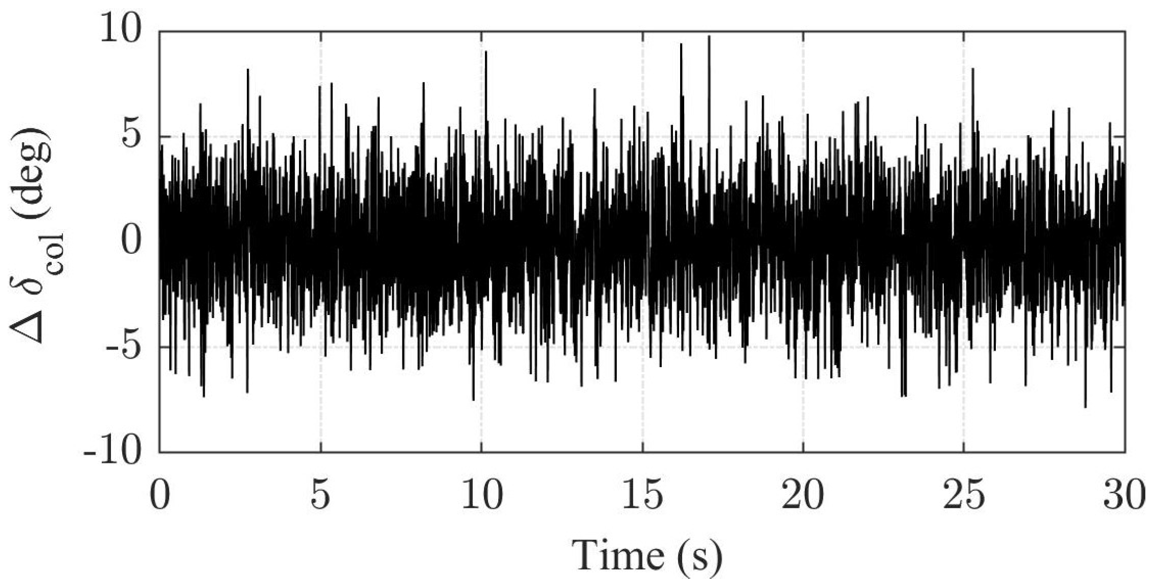
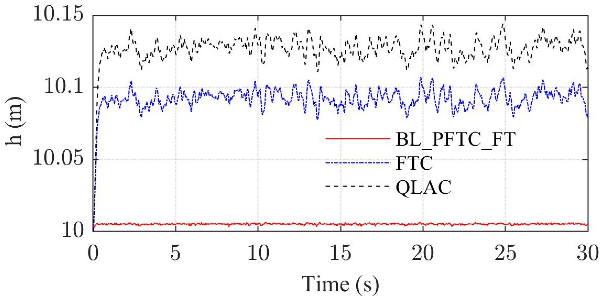
Furthermore, the fault-tolerant performance of the three methods is investigated in simulation experiments. As shown in Figure 3, total control perturbation caused by fluctuation of main rotor pitch mechanism. The vertical rate oscillation controlled by BL_PFTC_FT is confined in the range of −0.1 m/s to 0.1 m/s as shown in Figure 4, while the oscillation of FTC and QLAC are all over 0.2 m/s. Similarly, the stable height of BL_PFTC_FT is closer to the target height of 10 m in Figure 5, and the steady-state error is smaller than FTC and QLAC. The fault-tolerant capability has been enhanced to accommodate the total distance aroused by varible-pitch deviation.
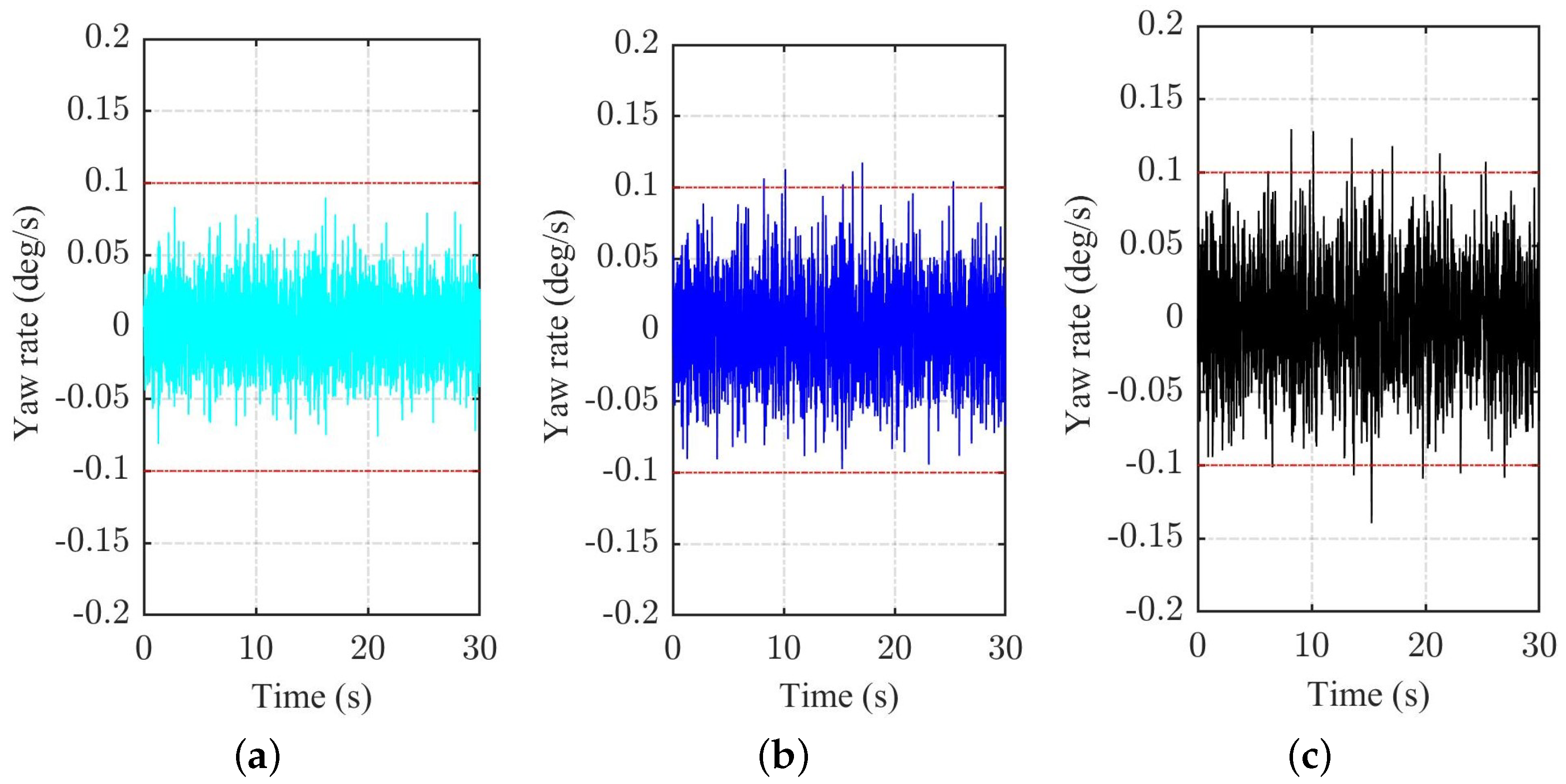
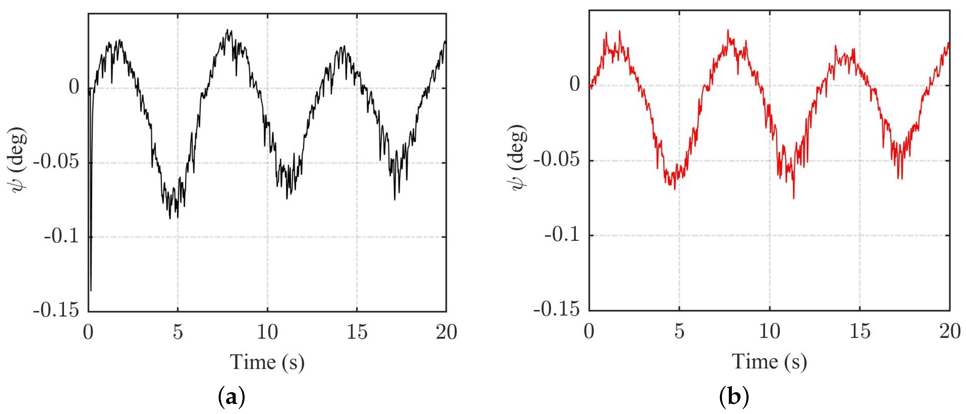
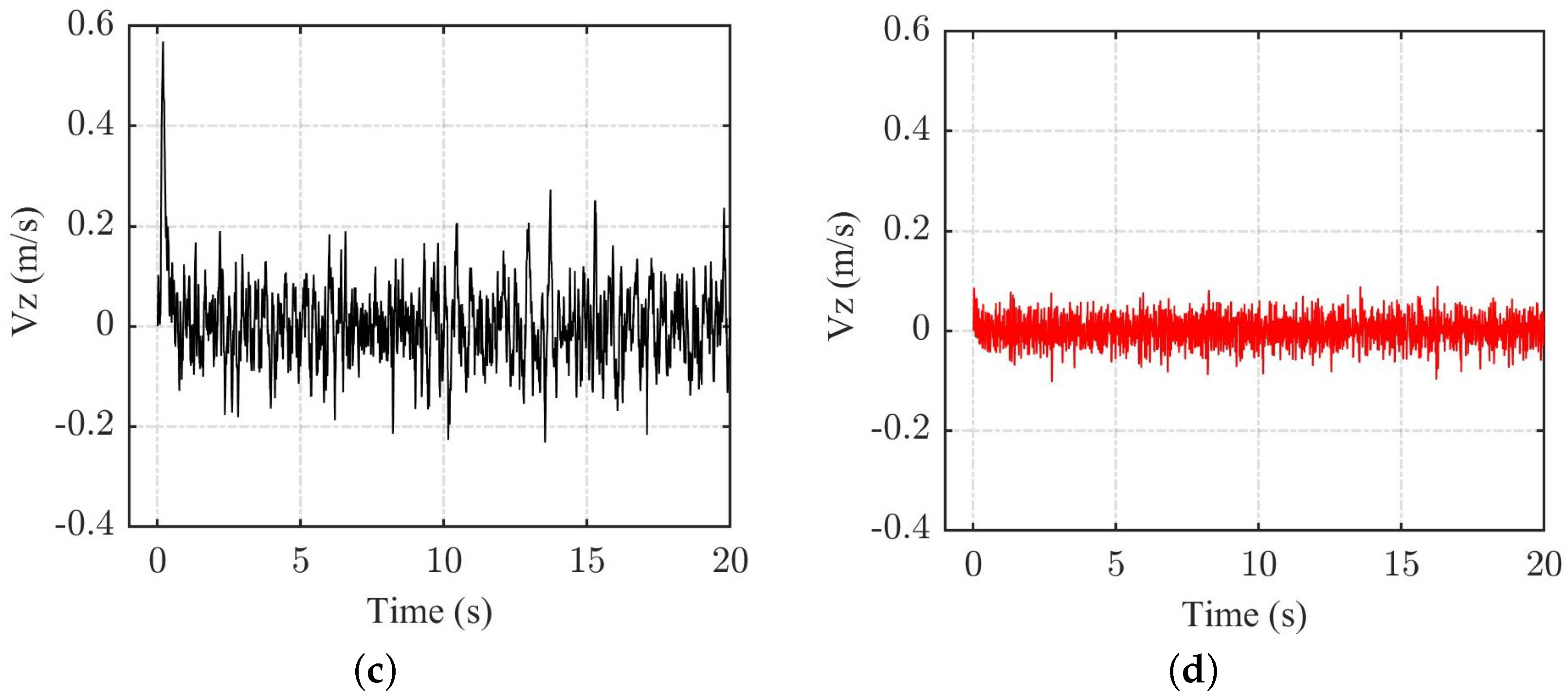
The fault tolerance performance of yaw channel is also investigated separately in the simulation. The output fluctuation of tail rotor control Δ δ p e d is set to the same amplitude as of the main rotor Δ δ c o l . In Figure 6, it can be seen that the yaw rate oscillation of BL_PFTC_FT is always within in the range of ± 0.1 deg/s, which is smaller than FTC and QLAC methods. Figure 7 shows the yaw angle ψ changing process, obviously, the amplitude of oscillation controlled by FTC or QLAC is larger than BL_PFTC_FT. Therefore, the BL_PFTC_FT controller has improved the capability of helicopter’s resistance to the output fluctuation of tail rotor pitch servo mechanism. Moreover, when yaw-vertical channels exist maneuvering fluctuations simultaneously, the simulation results verify the effect of auxiliary state Ψ designed in BL_PFTC_FT to improve the resistance to actuator fluctuations in Figure 8. The yaw angle and vertical rate are chattering augment without the auxiliary state as shown in Figure 8a,c, on the contrary in the diagrams of Figure 8b,d.
Further, the fault tolerance performance in yaw motion control is considered suffering paddle speed fluctuation when the unmanned helicopter is cruising at a horizontal speed of 40 km/h. the oscillation amplitude of speed Δ ω t r is set to be 500 r/min sinusoidal wave. Figure 9 illustrates the stabilizing process to yaw channel of the three controllers. Comparing with FTC and QLAC, the amplitude of yaw rate adjusted by BL_PFTC_FT is much smaller in whole process, following with FTC, QLAC has the largest rate fluctuation. It has similar situation for stabilizing the yaw angle in Figure 9b, therefore, BL_PFTC_FT has the fault tolerance capability to speed fluctuation of tail rotor.
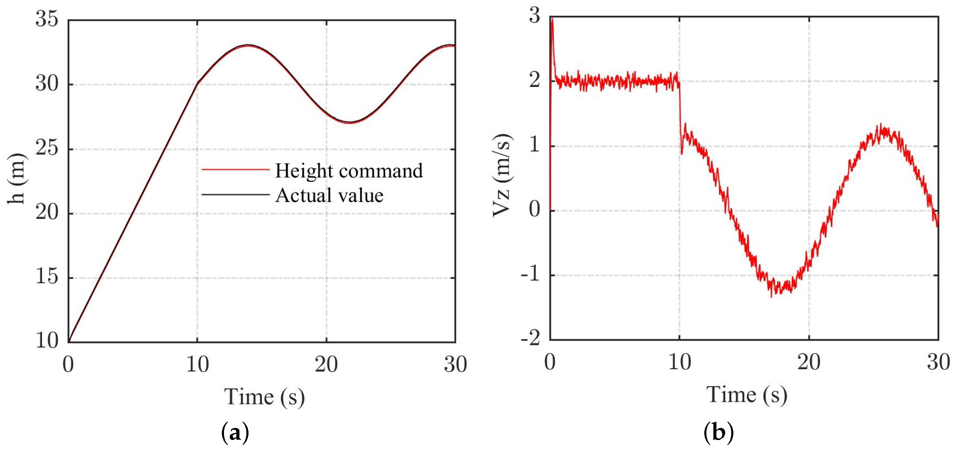
Finally, simulation experiment investigated the tracking capability of proposed controller when both main rotor and tail rotor suffering collective pitch maneuvering deviation and motor speed oscillation. The linear command tracking performance of yaw channel is shown in Figure 10, the tracking accuracy of yaw angle keeps well. Figure 10b gives the response process of yaw rate, amplitude is lower than 10 deg/s, it is much smaller than the suggested maximum tolerant value of 36 deg/s in reference [37]. Similarly, the helicopter prototype has high tracking accuracy of flight height illustrated in Figure 11a even under multi-channel faults. The vertical motion rate in Figure 11b keeps a fast response speed with a little chattering. In brief, the Proposed BL_PFTC_FT controller guarantees the dynamic tracking performance of yaw and vertical motion.

6. Conclusions

This paper proposed a barrier-Lyapunov function based practical FTC-FT control scheme for a class of strict-feedback multi-input and multi-output autonomous system with actuator faults, theoretical analysis indicates that the states of system are able to converge to the origin, and trajectories always keep within the given limitation, all signals satisfy the uniformly ultimate bound. Based on this scheme, we designed a FTC-FT controller with rate constraints to the yaw and vertical channels, The simulation results on the a helicopter prototype platform show its effectiveness and superiority, comparing with the traditional finite-time-convergence control and asymptotic convergence methods, it improves the yaw and vertical motion dynamics process and their rates are always keeping in the configured safe ranges. This fault-tolerant controller has the capability to resist pitch angle and speed fluctuation, and enhances the stability margin to an aircraft in presence of actuator deviation. Future work will focus on the extension test of other actuator failures and run on a real flight management computer.

Author Contributions

Conceptualization, P.T. and Y.D.; methodology, P.T.; software, C.Z.; validation, P.T., S.L. and Y.D.; formal analysis, P.T.; investigation, resources, Y.D.; writing—original draft preparation, P.T.; writing—review and editing, C.Z.; visualization, P.T.; supervision, Y.D.; project administration, Y.D.; funding acquisition, Y.D. All authors have read and agreed to the published version of the manuscript.

Funding

This research was partly funded by the Science and Technology Department of Sichuan Province, grant number: 2020YFSY0004.

Institutional Review Board Statement

Not applicable.

Informed Consent Statement

Not applicable.

Data Availability Statement

Data is contained within the article.

Conflicts of Interest

Authors Peng Tang, Chuangxin Zhao and Shizhe Liang were employed by the company AVIC Chengdu Aircraft Industrial (Group) Co., Ltd. The remaining authors declare that the research was conducted in the absence of any commercial or financial relationships that could be construed as a potential conflict of interest.

References

  1. Yin, Z.; Hu, N.; Chen, J.; Yang, Y.; Shen, G. A review of fault diagnosis, prognosis and health management for aircraft electromechanical actuators. IET Electr. Power Appl. 2022, 16, 1249–1272. [Google Scholar] [CrossRef]
  2. Jung, W.; Bang, H. Fault and Failure Tolerant Model Predictive Control of Quadrotor UAV. Int. J. Aeronaut. Space Sci. 2021, 22, 663–675. [Google Scholar] [CrossRef]
  3. Tang, P.; Zhang, F.; Ye, J.; Lin, D. An integral TSMC-based adaptive fault-tolerant control for quadrotor with external disturbances and parametric uncertainties. Aerosp. Sci. Technol. 2021, 109, 106415. [Google Scholar] [CrossRef]
  4. Sun, S.; Wang, X.; Chu, Q.; Visser, C.D. Incremental Nonlinear Fault-Tolerant Control of a Quadrotor with Complete Loss of Two Opposing Rotors. IEEE Trans. Robot. 2021, 37, 116–130. [Google Scholar] [CrossRef]
  5. Bounemeur, A.; Chemachema, M. Adaptive fuzzy fault-tolerant control using Nussbaum-type function with state-dependent actuator failures. Neural Comput. Appl. 2021, 33, 191–208. [Google Scholar] [CrossRef]
  6. Wang, X.; Zhou, Y.; Huang, T.; Chakrabarti, P. Event-triggered adaptive fault-tolerant control for a class of nonlinear multiagent systems with sensor and actuator faults. IEEE Trans. Circuits Syst. Regul. Pap. 2022, 69, 4203–4214. [Google Scholar] [CrossRef]
  7. Wang, G.; Xia, H. Fault-tolerant learning control of air-breathing hypersonic vehicles with uncertain parameters and actuator faults. Expert Syst. Appl. 2024, 238, 121874. [Google Scholar] [CrossRef]
  8. Lu, Y.; Jia, Z.; Liu, X.; Lu, K. Output feedback fault-tolerant control for hypersonic flight vehicles with non-affine actuator faults. Acta Astronaut. 2022, 193, 324–337. [Google Scholar] [CrossRef]
  9. Zhang, K.; Jiang, B.; Yan, X.; Mao, Z.; Polycarpou, M.M. Fault-tolerant control for systems with unmatched actuator faults and disturbances. IEEE Trans. Autom. Control 2021, 66, 1725–1732. [Google Scholar] [CrossRef]
  10. Chen, F.; Zhang, K.; Jiang, B.; Wen, C. Adaptive sliding mode observer-based robust fault reconstruction for a helicopter with actuator fault. Asian J. Control 2016, 18, 1558–1565. [Google Scholar] [CrossRef]
  11. Ortiz-Torres, G.; Castillo, P.; Sorcia-Vázquez, F.D.; Rumbo-Morales, J.Y.; Brizuela-Mendoza, J.A.; De La Cruz-Soto, J.; Martínez-García, M. Fault estimation and fault tolerant control strategies applied to VTOL aerial vehicles with soft and aggressive actuator faults. IEEE Access 2020, 8, 10649–10661. [Google Scholar] [CrossRef]
  12. Chang, J.; Cieslak, J.; Guo, Z.; Henry, D. On the synthesis of a sliding-mode-observer-based adaptive fault-tolerant flight control scheme. ISA Trans. 2021, 111, 8–23. [Google Scholar] [CrossRef]
  13. Liu, Y.; Hong, S.; Zio, E.; Liu, J. Fault Diagnosis and Reconfigurable Control for Commercial Aircraft with Multiple Faults and Actuator Saturation. Aerospace 2021, 8, 108. [Google Scholar] [CrossRef]
  14. Guo, B.; Dian, S.; Zhao, T. Event-driven-observer-based fuzzy fault-tolerant control for nonlinear system with actuator fault. Nonlinear Dyn. 2022, 107, 3505–3519. [Google Scholar] [CrossRef]
  15. Yan, K.; Chen, M.; Wu, Q.; Lu, K. Robust attitude fault-tolerant control for unmanned autonomous helicopter with flapping dynamics and actuator faults. Trans. Inst. Meas. Control 2019, 41, 1266–1277. [Google Scholar] [CrossRef]
  16. Marcos, A.; Waitman, S.; Sato, M. Fault tolerant linear parameter varying flight control design, verification and validation. J. Frankl. Inst. 2022, 359, 653–676. [Google Scholar] [CrossRef]
  17. Quadros, M.M.; de Bessa, I.V.; Leite, V.J.; Palhares, R.M. Fault tolerant control for linear parameter varying systems: An improved robust virtual actuator and sensor approach. ISA Trans. 2020, 104, 356–369. [Google Scholar] [CrossRef] [PubMed]
  18. Wang, B.; Shen, Y.; Zhang, Y. Active fault-tolerant control for a quadrotor helicopter against actuator faults and model uncertainties. Aerosp. Sci. Technol. 2020, 99, 105745. [Google Scholar] [CrossRef]
  19. Sun, X.; Wang, X.; Zhou, Z.; Zhou, Z. Active Fault-Tolerant Control Strategy for More Electric Aircraft under Actuation System Failure. Actuators 2020, 9, 122. [Google Scholar] [CrossRef]
  20. Wang, B.; Zhu, D.; Han, L.; Gao, H.; Gao, Z.; Zhang, Y. Adaptive fault-tolerant control of a hybrid canard rotor/wing uav under transition flight subject to actuator faults and model uncertainties. IEEE Trans. Aerosp. Electron. Syst. 2023, 59, 4559–4574. [Google Scholar] [CrossRef]
  21. Zhang, N.; Gai, W.; Zhong, M.; Zhang, J. A fast finite-time convergent guidance law with nonlinear disturbance observer for unmanned aerial vehicles collision avoidance. Aerosp. Sci. Technol. 2019, 86, 204–214. [Google Scholar] [CrossRef]
  22. Yu, W.; Yan, J.; Pan, X.; Tan, S.; Cao, H.; Song, Y. Fault-tolerant attitude tracking control with practical finite time convergence for unmanned aerial vehicles under actuation faults. Int. J. Robust Nonlinear Control. 2022, 32, 3737–3753. [Google Scholar] [CrossRef]
  23. Jiang, T.; Lin, D.; Song, T. Finite-time control for small-scale unmanned helicopter with disturbances. Nonlinear Dyn. 2019, 96, 1747–1763. [Google Scholar] [CrossRef]
  24. Jiang, T.; Lin, D. Fast finite-time backstepping for helicopters under input constraints and perturbations. Int. J. Syst. Sci. 2020, 51, 2868–2882. [Google Scholar] [CrossRef]
  25. Fang, X.; Liu, F. High-order mismatched disturbance rejection control for small-scale unmanned helicopter via continuous nonsingular terminal sliding-mode approach. Int. J. Robust Nonlinear Control. 2019, 29, 935–948. [Google Scholar] [CrossRef]
  26. Liu, N.; Shao, X.; Yang, W.J.I.A. Integral barrier Lyapunov function based saturated dynamic surface control for vision-based quadrotors via back-stepping. IEEE Access 2018, 6, 63292–63304. [Google Scholar] [CrossRef]
  27. Zheng, Z.; Ruan, L.; Zhu, M. Output-constrained tracking control of an underactuated autonomous underwater vehicle with uncertainties. Ocean. Eng. 2019, 175, 241–250. [Google Scholar] [CrossRef]
  28. Xu, B.; Shi, Z.; Sun, F.; He, W. Barrier Lyapunov Function Based Learning Control of Hypersonic Flight Vehicle with AOA Constraint and Actuator Faults. IEEE Trans. Cybern. 2019, 49, 1047–1057. [Google Scholar] [CrossRef]
  29. Ngo, K.B.; Mahony, R.; Jiang, Z.P. Integrator backstepping using barrier functions for systems with multiple state constraints. In Proceedings of the 44th IEEE Conference on Decision and Control, and the European Control Conference, Seville, Spain, 15 December 2005; pp. 8306–8312. [Google Scholar] [CrossRef]
  30. Li, H.; Zhao, S.; He, W.; Lu, R. Adaptive finite-time tracking control of full state constrained nonlinear systems with dead-zone. Automatica 2019, 100, 99–107. [Google Scholar] [CrossRef]
  31. Dong, R.Q.; Wu, Y.Y.; Zhang, Y.; Wu, A.G. Adaptive Backstepping Attitude Control Law with L2 -Gain Performance for Flexible Spacecraft. Int. J. Aerosp. Eng. 2019, 2019, 6392175. [Google Scholar] [CrossRef]
  32. Levant, A. Higher-order sliding modes, differentiation and output-feedback control. Int. J. Control 2003, 76, 924–941. [Google Scholar] [CrossRef]
  33. Yu, S.; Yu, X.; Shirinzadeh, B.; Man, Z. Continuous finite-time control for robotic manipulators with terminal sliding mode. Automatica 2005, 41, 1957–1964. [Google Scholar] [CrossRef]
  34. Yu, J.; Shi, P.; Zhao, L. Finite-time command filtered backstepping control for a class of nonlinear systems. Automatica 2018, 92, 173–180. [Google Scholar] [CrossRef]
  35. Fang, X.; Liu, F.; Ding, Z. Robust control of unmanned helicopters with high-order mismatched disturbances via disturbance-compensation-gain construction approach. J. Frankl. Inst. 2018, 355, 7158–7177. [Google Scholar] [CrossRef]
  36. Johnson, E.; Mishra, S. Flight Simulation for the Development of an Experimental UAV. In Proceedings of the AIAA Modeling and Simulation Technologies Conference and Exhibit, Monterey, CA, USA, 5–8 August 2002; p. 4975. [Google Scholar]
  37. Cai, G.; Chen, B.M.; Lee, T.H. Unmanned Rotorcraft Systems; Springer Science & Business Media: Berlin/Heidelberg, Germany, 2011. [Google Scholar]
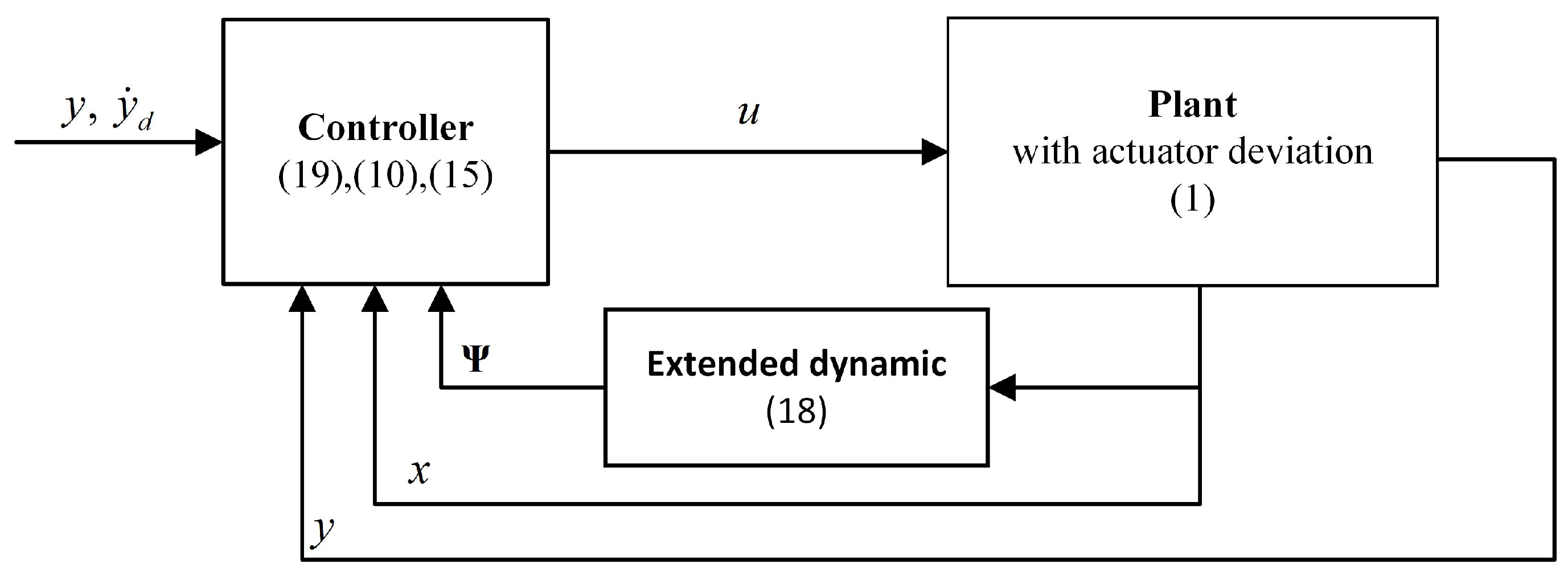
Figure 1. Diagram of FTC-FT control scheme.
Algorithms 17 00196 g001
Figure 2. Transient performance comparison of yaw and vertical motion. (a) Yaw rate; (b) Yaw angle; (c) Vertical velocity; (d) Height.
Algorithms 17 00196 g002
Figure 3. Actuator fluctuation of main rotor.
Algorithms 17 00196 g003
Figure 4. Vertical dynamics comparison in case of δ c o l deviation. (a) BL_PFTC_FT; (b) FTC; (c) QLAC.
Algorithms 17 00196 g004
Figure 5. Height control comparison in case of δ c o l deviation.
Algorithms 17 00196 g005
Figure 6. Vertical dynamics comparison in case of δ t r deviation. (a) BL_PFTC_FT; (b) FTC; (c) QLAC.
Algorithms 17 00196 g006
Figure 7. Yaw angle control comparison in case of δ t r deviation.
Algorithms 17 00196 g007
Figure 8. Vertical dynamics comparison in case of δ t r deviation. (a) No compensation of auxiliary state; (b) After compensation; (c) No compensation of auxiliary state; (d) After compensation.
Algorithms 17 00196 g008aAlgorithms 17 00196 g008b
Figure 9. Yaw stabilization comparison in case of Tail rotor motor fluctuation. (a) Yaw rate; (b) Yaw angle.
Algorithms 17 00196 g009
Figure 10. Yaw channel performance in case of both δ c o l , δ t r and motor deviation. (a) Yaw rate; (b) Yaw angle.
Algorithms 17 00196 g010
Figure 11. Vertical channel performance in case of both δ c o l , δ t r and motor deviation. (a) Height; (b) Vertical velocity.
Algorithms 17 00196 g011
Disclaimer/Publisher’s Note: The statements, opinions and data contained in all publications are solely those of the individual author(s) and contributor(s) and not of MDPI and/or the editor(s). MDPI and/or the editor(s) disclaim responsibility for any injury to people or property resulting from any ideas, methods, instructions or products referred to in the content.