
Effects of Grain Pattern on the Rolling Shear Properties of Wood in Cross-Laminated Timber


Abstract
:1. Introduction
2. Materials and Methods
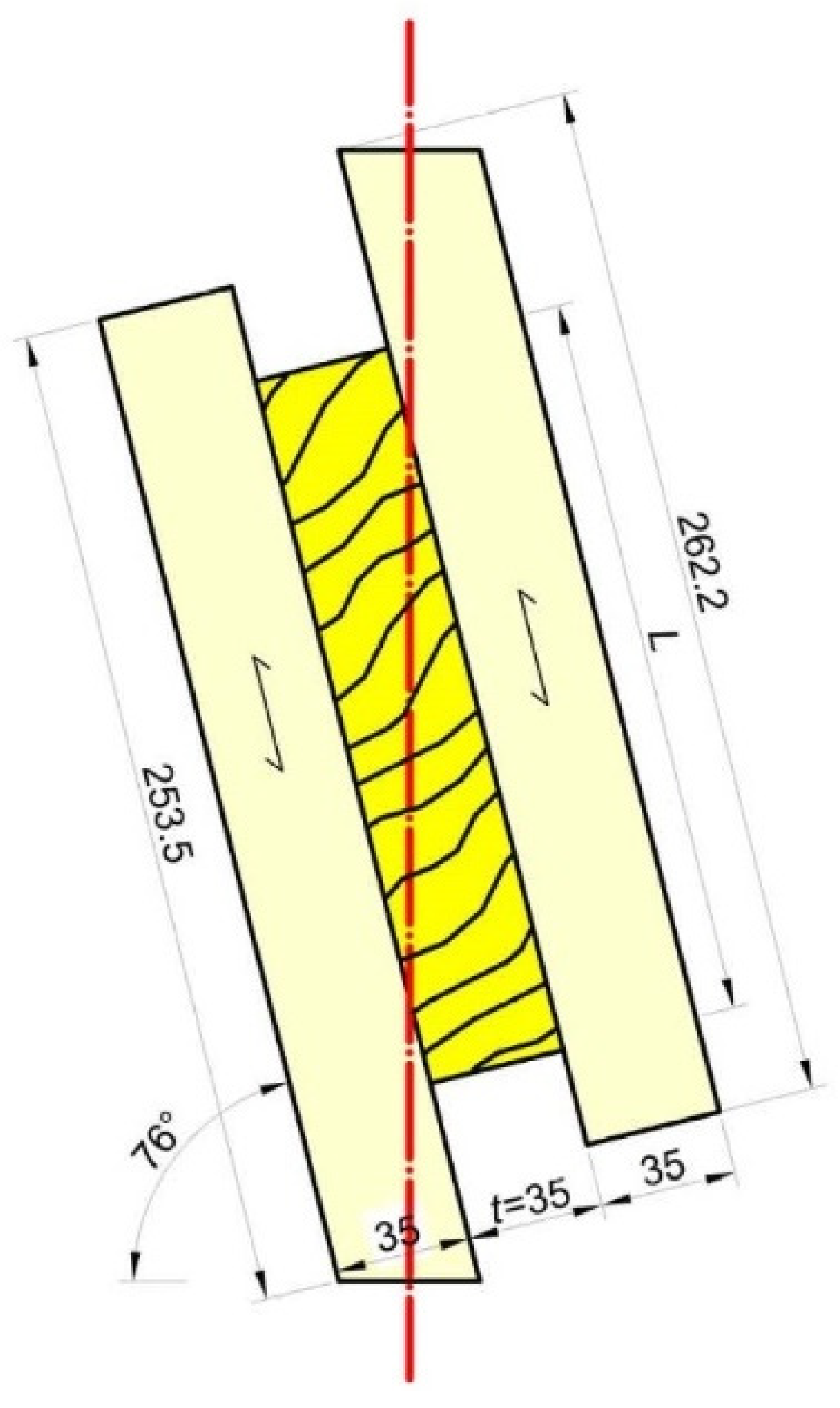
2.1. Materials
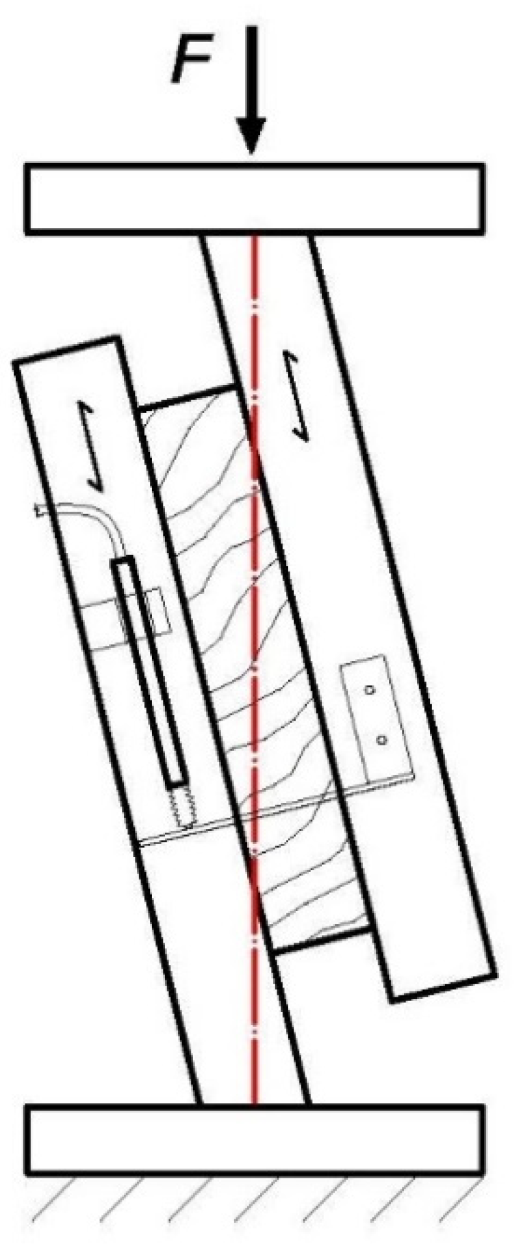
2.2. Methods
3. Results and Discussion
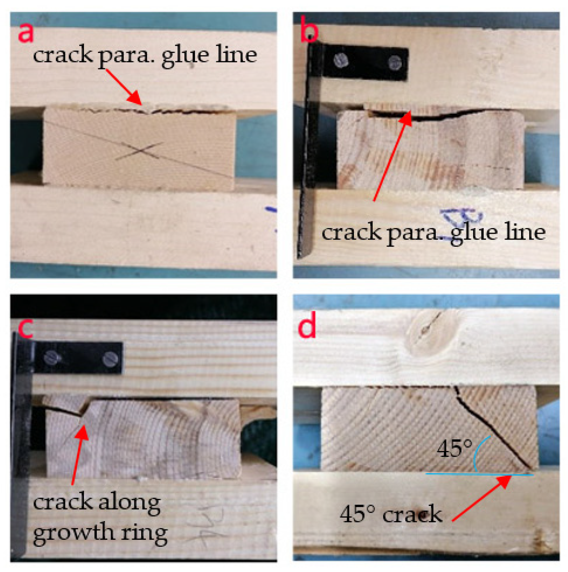
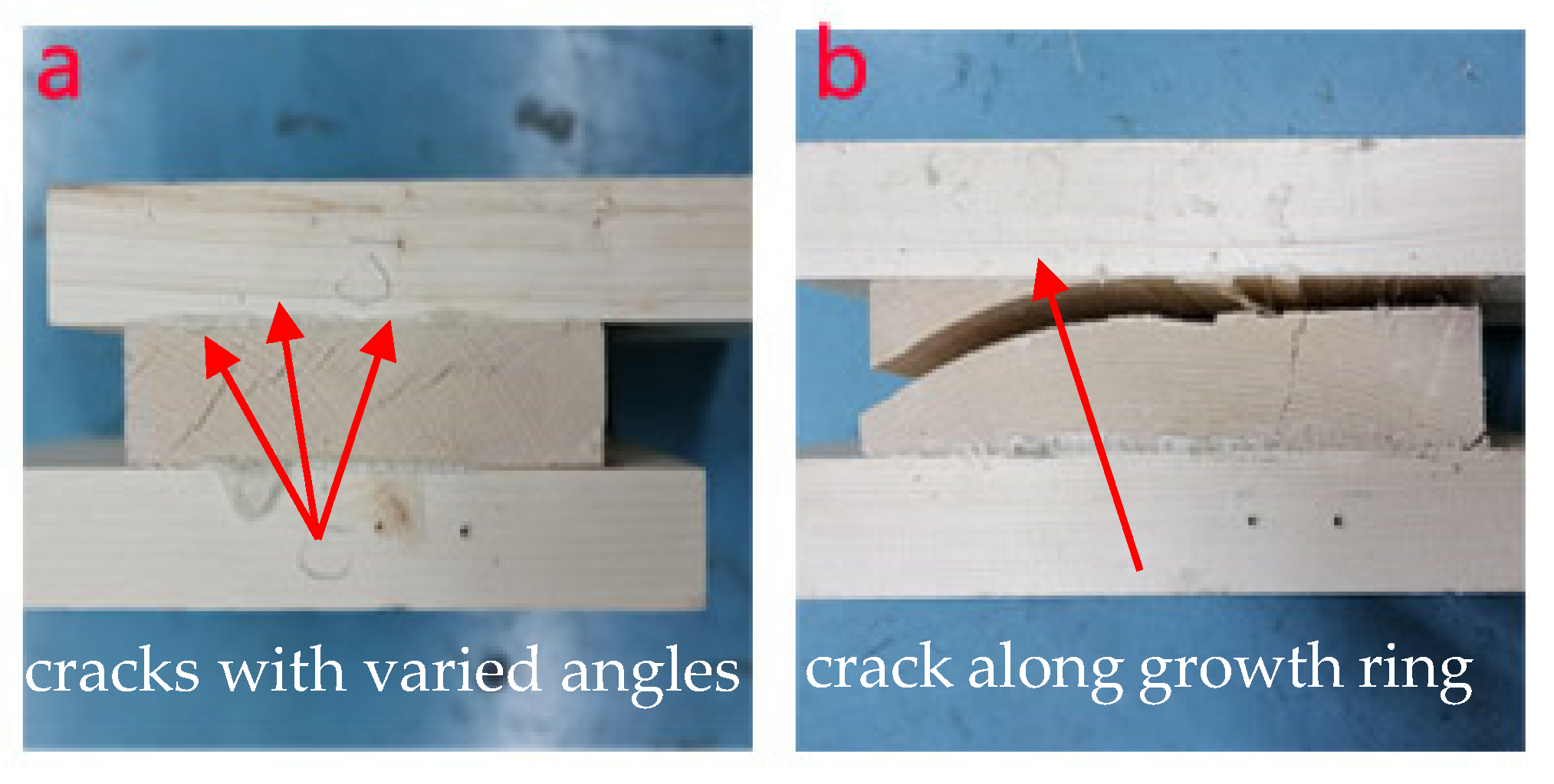
3.1. Failure Modes
3.2. Rolling Shear Modulus and Strength
4. Theoretical Work
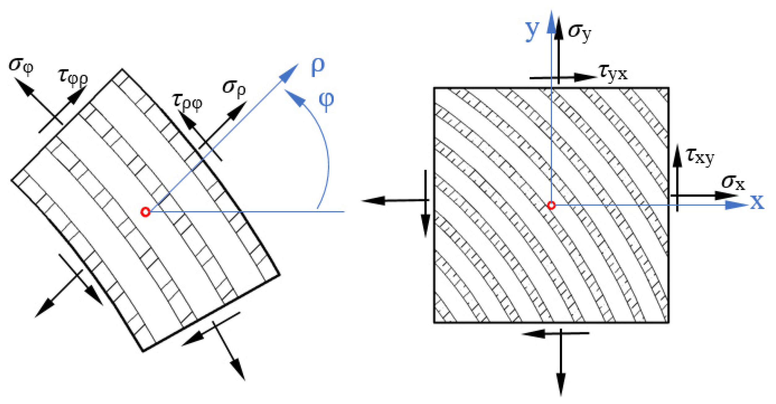
4.1. Mechanism of the Rolling Shear
4.2. Relationship of Grain and Rolling Shear Modulus
5. Conclusions
- (1)
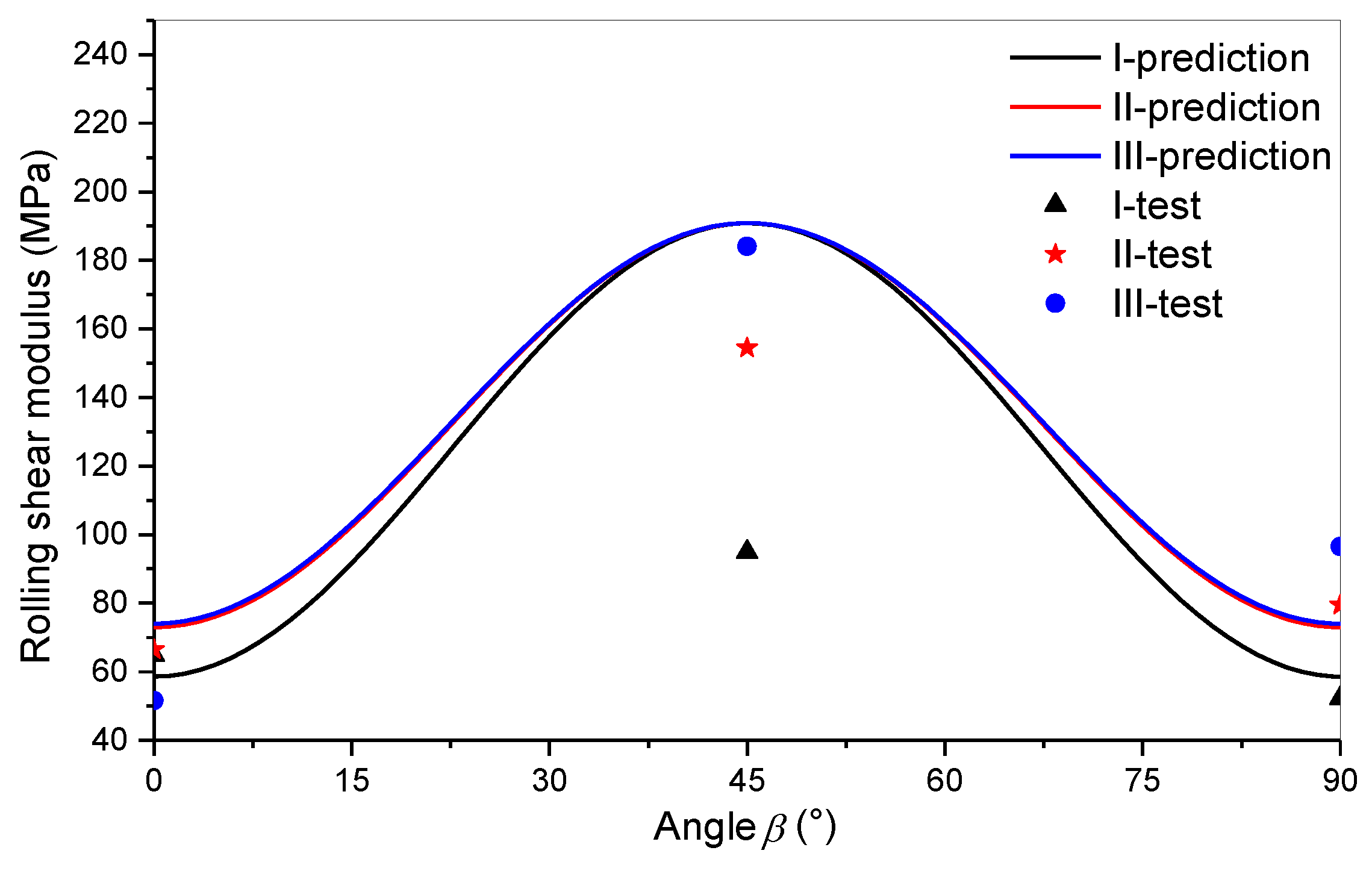
- The apparent rolling shear modulus was the largest for the in-between grain-mode specimens (at a grain angle of 45°). However, it had the lowest values for parallel (0°) and right angle (90°) grain-mode specimens.
- (2)
- The rolling shear strength of the wood increased slightly with the aspect ratio because the stress concentration is very severe in small aspect ratio specimens.
- (1)
- The rolling shear moduli of 0° and 90° grain-mode of the wood were the same. This value can be called the pure rolling shear modulus.
- (2)
- The rolling shear moduli of the wood with angles other than 0° and 90° can be calculated from the pure rolling shear modulus and grain angle. Therefore, these moduli can be called the apparent rolling shear moduli.
- (3)
- Using 0° and 90° grain-mode specimens to determine the pure rolling shear modulus and strength of the wood is recommended.
Author Contributions
Funding
Data Availability Statement
Acknowledgments
Conflicts of Interest
References
- Gagnon, S.; Pirvu, C. CLT Handbook: Cross-Laminated Timber; FPInnovations: Montreal, QC, Canada, 2011. [Google Scholar]
- Brandner, R.; Flatscher, G.; Ringhofer, A.; Schickhofer, G. Cross laminated timber (CLT): Overview and development. Eur. J. Wood Wood Prod. 2016, 74, 331–351. [Google Scholar] [CrossRef]
- Wang, Z.; Gong, M.; Chui, Y. Mechanical Properties of Laminated Strand Lumber and Hybrid Cross-laminated Timber. Constr. Build. Mater. 2015, 101 Pt 2, 622–627. [Google Scholar] [CrossRef]
- Dahl, K.B.; Malo, K.A. Linear shear properties of spruce softwood. Wood Sci. Technol. 2009, 43, 499–525. [Google Scholar] [CrossRef]
- Zhou, Q. Development of Evaluation Methodology for Rolling Shear Properties in Cross Laminated Timber (CLT). Ph.D. Thesis, University of New Brunswick, Fredericton, NB, Canada, 2013. [Google Scholar]
- Ehrhart, T.; Brandner, R.; Schickhofer, G.; Frangi, A. Rolling shear properties of some European timber species with focus on cross laminated timber (CLT): Test configuration and parameter study. In Proceedings of the Meeting 48 International Network on Timber Engineering Research, Šibenik, Croatia, 24–27 August 2015. [Google Scholar]
- Aicher, S.; Christian, Z.; Hirsch, M. Rolling shear modulus and strength of beech wood laminations. Holzforschung 2016, 70, 773–781. [Google Scholar] [CrossRef]
- Aicher, S.; Dill-Langer, G. Basic considerations to rolling shear modulus in wooden boards. Otto Graf J. 2000, 11, 157–165. [Google Scholar]
- Wang, Z. Effect of macroscopic characteristics of sawn timber on rolling shear properties of cross layer of CLT. Master’s Thesis, Nanjing Forestry University, Nanjing, China, 2017. (In Chinese). [Google Scholar]
- Cai, S. Research on CLT Rolling Shear Performance Based on Digital Image Correlation Method. Master’s Thesis, Nanjing Forestry University, Nanjing, China, 2019. (In Chinese). [Google Scholar]
- Ehrhart, T.; Brandner, R. Rolling shear: Test configurations and properties of some European soft and hardwood species. Eng. Struct. 2018, 172, 554–572. [Google Scholar] [CrossRef]
- National Forestry and Grassland Administration. LY/T 3039. Cross Laminated Timber; Standards Press: Beijing, China, 2018. [Google Scholar]
- European Committee for Standardization (CEN). Timber Structures—Structural Timber and Glued Laminated Timber-Determination of Some Physical and Mechanical Properties; European Committee for Standardization (CEN): Bruxelles, Belgium, 2012. [Google Scholar]
- Mestek, P. Punktgestützte Flächentragwerke aus Brettsperrholz (BSP): Schubbemessung unter Berücksichtigung von Schubverstärkungen. Ph.D. Thesis, Technische Universität München, München, Germany, 2011. (In German). [Google Scholar]
- Wu, G.; Zhong, Y.; Zhao, R.; Ren, H. Pre-reinforcing the mortise-tenon joints with near-surface-mounted glued-in rods. Struct. Des. Tall. Spec. 2021, 30, e1826. [Google Scholar]
- Thelandersson, S.; Larsen, H.J. Timber Engineering; John Wiley & Sons: West Sussex, UK, 2003. [Google Scholar]
- Chen, H.F.; Salip, A.F. Elasticity and Plasticity; China Arehitecture Publishing & Media Co., Ltd.: Beijing, China, 2005. [Google Scholar]
- Belytschko, T.; Liu, W.K.; Moran, B. Finite Elements for Nonlinear Continua and Structures; John Wiley & Sons: New York, NY, USA, 1996. [Google Scholar]
- Barrett, J.D.; Jones, E.D.; Lau, W. Canadian Lumber Properties; Canadian Wood Council: Ottawa, ON, Canada, 1994. [Google Scholar]
- Flaig, M. Biegeträger aus Brettsperrholzbei Beanspruchung in Plattenebene. Ph.D. Thesis, Karlsruher Institut für Technologie, Karlsruhe, Germany, 2013. (In German). [Google Scholar]


| Group | Apparent Rolling Shear Modulus | Rolling Shear Strength | ||||
|---|---|---|---|---|---|---|
| Average (MPa) | COV | Sig 1 | Average (MPa) | COV | Sig | |
| I-0 | 64.9 | 0.40 | ab | 1.26 | 0.38 | ab |
| I-45 | 94.9 | 0.24 | a | 1.00 | 0.18 | a |
| I-90 | 52.2 | 0.48 | b | 1.68 | 0.13 | b |
| II-0 | 66.5 | 0.25 | ab | 1.74 | 0.12 | a |
| II-45 | 154.5 | 0.57 | c | 1.38 | 0.39 | a |
| II-90 | 79.5 | 0.19 | a | 1.67 | 0.17 | a |
| III-0 | 51.6 | 0.43 | a | 1.44 | 0.11 | a |
| III-45 | 184.1 | 0.29 | b | 1.73 | 0.16 | a |
| III-90 | 96.5 | 0.16 | ac | 1.82 | 0.22 | a |
| Average | 93.9 | 0.33 | - | 1.52 | 0.21 | - |
Publisher’s Note: MDPI stays neutral with regard to jurisdictional claims in published maps and institutional affiliations. |
© 2021 by the authors. Licensee MDPI, Basel, Switzerland. This article is an open access article distributed under the terms and conditions of the Creative Commons Attribution (CC BY) license (https://creativecommons.org/licenses/by/4.0/).
Share and Cite
Wu, G.; Zhong, Y.; Ren, H. Effects of Grain Pattern on the Rolling Shear Properties of Wood in Cross-Laminated Timber. Forests 2021, 12, 668. https://doi.org/10.3390/f12060668
Wu G, Zhong Y, Ren H. Effects of Grain Pattern on the Rolling Shear Properties of Wood in Cross-Laminated Timber. Forests. 2021; 12(6):668. https://doi.org/10.3390/f12060668
Chicago/Turabian StyleWu, Guofang, Yong Zhong, and Haiqing Ren. 2021. "Effects of Grain Pattern on the Rolling Shear Properties of Wood in Cross-Laminated Timber" Forests 12, no. 6: 668. https://doi.org/10.3390/f12060668