
Flexural Properties of Multiple Bamboo Beams with Connection Joints
 ,
,
Abstract
:1. Introduction
2. Materials and Methods
2.1. Materials
2.2. Preparation of Specimens
2.3. Preparation of Sleeve-Nailed Specimens
2.4. Preparation of Specimens for Flexural Test
2.5. Strain Measurement
2.6. Test Method and Equipment
3. Results and Discussion
3.1. The Bending Properties of Single-Culm Specimens
3.2. Two-Beam Specimen Test Result Analysis
3.2.1. Test Results
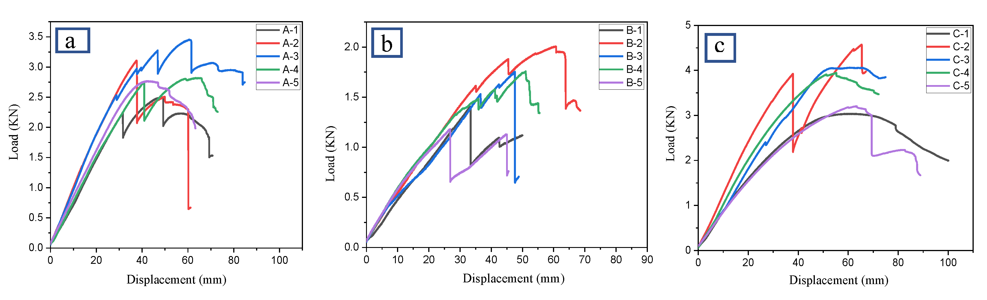
3.2.2. Load-Displacement Curve Analysis of the Two-Culm Bamboo Columns
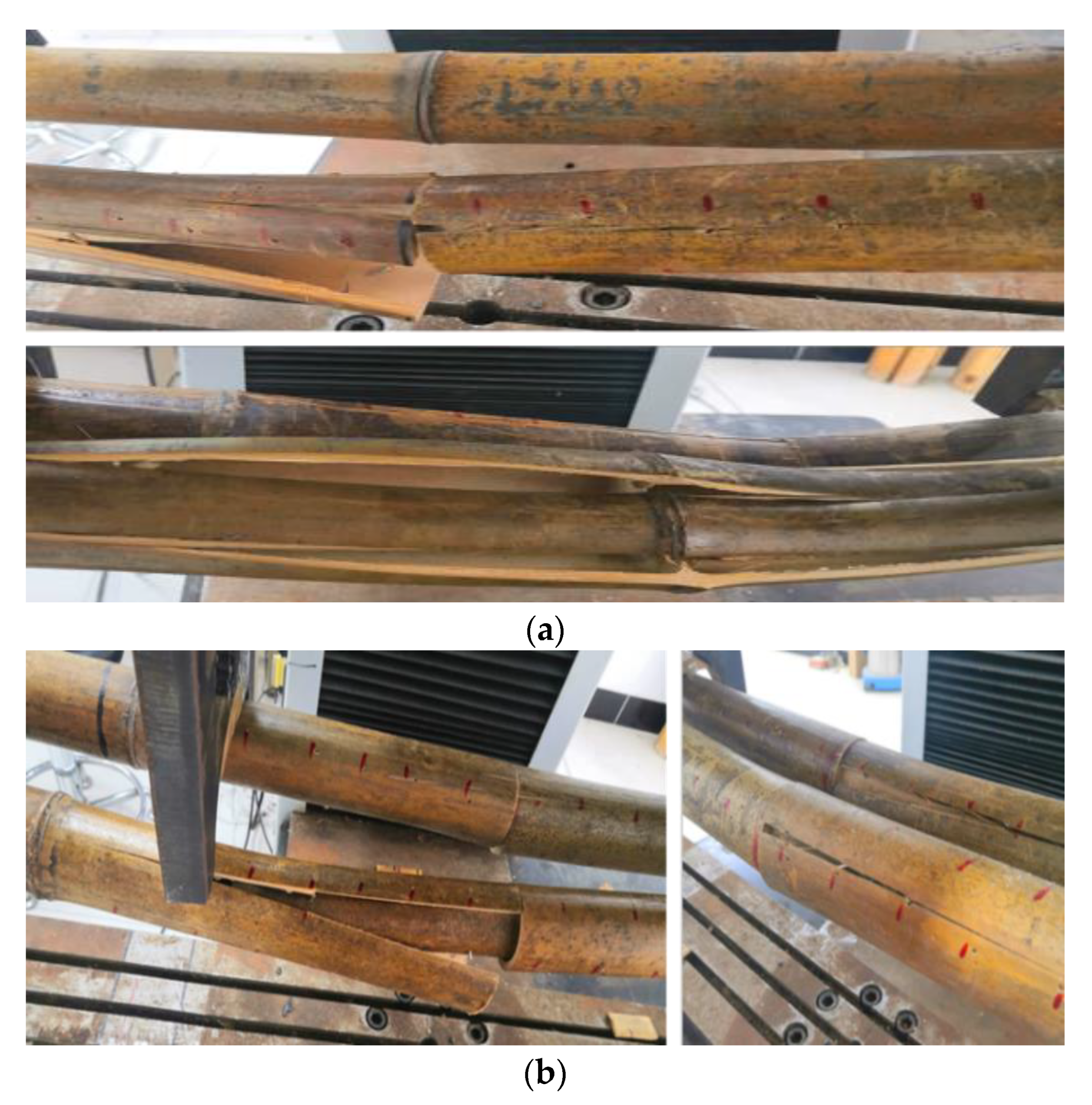
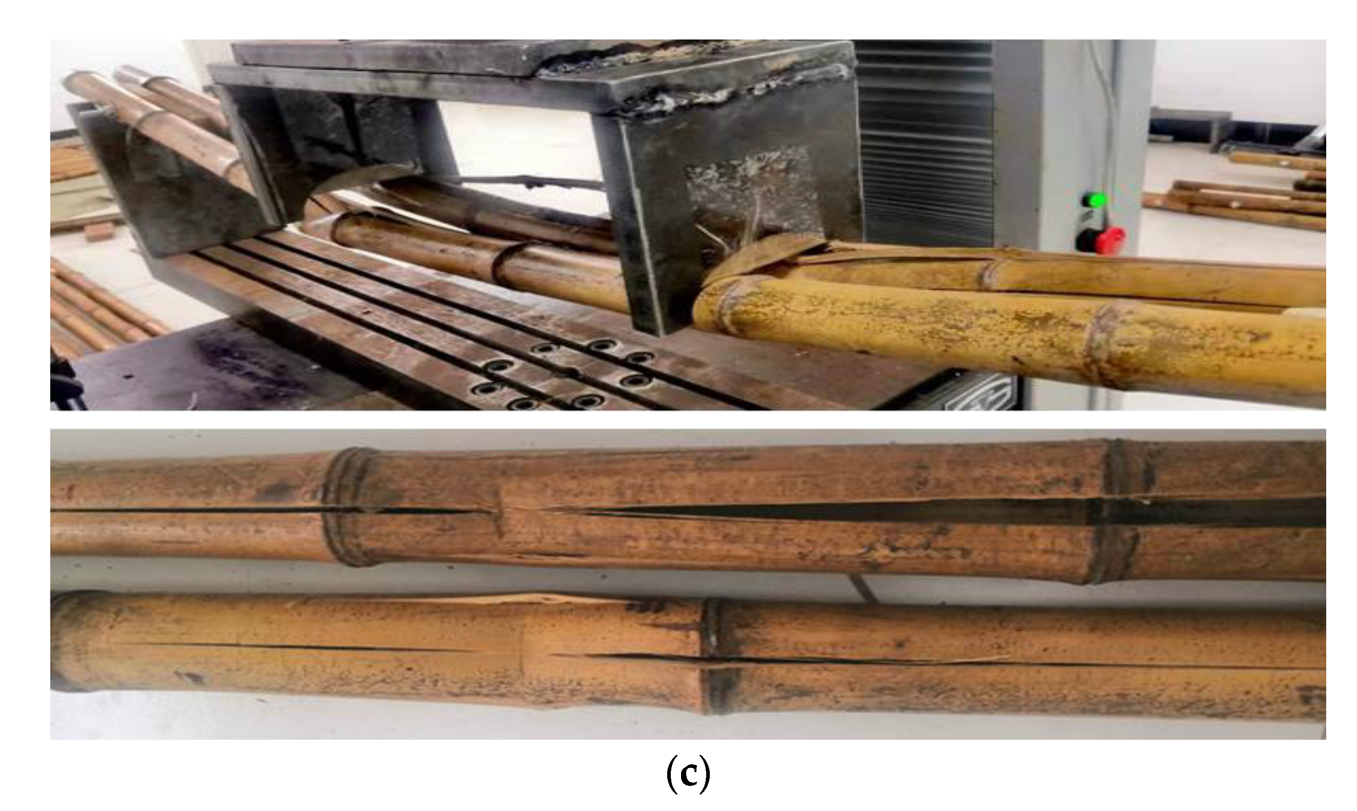
3.2.3. Analysis of Damage Form of the Two-Culm Bamboo Columns
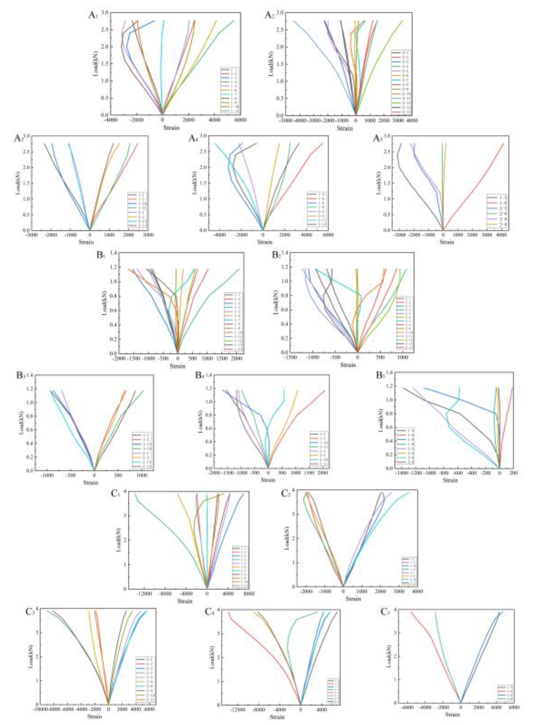
3.2.4. Load-Strain Curve Analysis of the Two-Culm Bamboo Columns
4. Conclusions
- (1)
- The single sleeve-nailed bamboo specimens always cracked at the joints. They appeared to undergo brittle failure with shear splitting due to the inserted bamboo culm. The original bamboo appeared to undergo longitudinal splitting and local crushing.
- (2)
- The bending maximum load of the single sleeve-type nailed specimen was relatively small, which was 63.87% lower than that of the complete single bamboo specimen, while the bending capacity of the two-culm beams increased more significantly than the single one. Type V had the largest flexural bearing capacity, followed by Type III, and Type IV had the smallest one. Compared with the maximum load of the single specimen, Type III increased by 75.09%, while Type IV increased by 54.94%.
- (3)
- The stiffnesses of the single bamboo specimen for Types I and II were 33 N·mm−1 and 47 N·mm−1, respectively. The stiffnesses of the two-culm beams of Types III, IV, and V were 83.07 N·mm−1, 42.46 N·mm−1, and 96.25 N·mm−1, respectively. The stiffnesses of Types III and V were higher than that of the single one.
Author Contributions
Funding
Institutional Review Board Statement
Informed Consent Statement
Data Availability Statement
Conflicts of Interest
References
- Jiang, Z.H. Bamboo and Rattan in the World; China Forestry Publishing House: Beijing, China, 2007. [Google Scholar]
- Zhang, W.F.; Wang, G.; Cheng, H.T.; Chen, F.M.; Zhan, X.M. Research and Utilization of Bamboo Culms. J. Bamboo Res. 2011, 30, 1–4. [Google Scholar]
- van der Lugt, P.; van den Dobbelsteen, A.A.J.F.; Janssen, J.J.A. An Environmental, Economic and Practical Assessment of Bamboo as a Building Material for Supporting Structures. Constr. Build. Mater. 2006, 20, 648–656. [Google Scholar] [CrossRef]
- Yan, Y.; Fei, B.H. Application of Bamboo Components in Architecture. J. Anhui Agric. Univ. 2020, 47, 205–210. [Google Scholar]
- Zhang, D.; Wang, G.; Zhang, W.F. Mechanical properties of Phyllostachys pubescens. J. Cent. South Univ. For. Technol. 2012, 32, 119–123. [Google Scholar]
- Awalluddin, D.; Ariffin, M.A.M.; Osman, M.H.; Hussin, M.W.; Ismail, M.A.; Lee, H.S.; Lim, N.H.A.S. Mechanical properties of different bamboo species. In MATEC Web of Conferences; EDP Sciences: Les Ulis, France, 2017; Volume 138, p. 01024. [Google Scholar]
- Lee, P.H.; Odlin, M.; Yin, H.M. Development of a hollow cylinder test for the elastic modulus distribution and the ultimate strength of bamboo. Constr. Build. Mater. 2014, 51, 235–243. [Google Scholar] [CrossRef]
- Xiao, Y.; Wu, Y.; Li, J.; Yang, R.Z. An experimental study on shear strength of glubam. Constr. Build. Mater. 2017, 150, 490–500. [Google Scholar] [CrossRef]
- Chung, K.F.; Yu, W.K. Mechanical properties of structural bamboo for bamboo scaffoldings. Eng. Struct. 2002, 24, 429–442. [Google Scholar] [CrossRef]
- Disén, K.; Clouston, P.L. Buiding with Bamboo:A Review of Culm Connection Technology. J. Green Build. 2013, 8, 83–93. [Google Scholar] [CrossRef]
- Hong, C.; Li, H.; Lorenzo, R.; Wu, G.; Corbi, I.; Corbi, O.; Xiong, Z.; Yang, D.; Zhang, H. Review on Connections for Original Bamboo Structures. J. Renew. Mater. 2019, 7, 713–730. [Google Scholar] [CrossRef] [Green Version]
- Moran, R.; García, J.J. Bamboo joints with steel clamps capable of transmitting moment. Constr. Build. Mater. 2019, 216, 249–260. [Google Scholar] [CrossRef]
- Seixas, M.; Moreira, L.E.; Bina, J.; Ripper, J.L.M. Design and analysis of a self-supporting bamboo roof structure applying flexible connections. In Proceedings of the IASS Annual Symposia, Boston, MA, USA, 16 July 2018; Volume 20, pp. 1–9. [Google Scholar]
- Wu, S.L. Study of Bamboo Architecture Structural Joint and Its Design Expression. Ph.D. Thesis, Nanjing University, Nanjing, China, 2018. [Google Scholar]
- Sonar, I.P.; Siddhaye, V.R. Theoretical and experimental investigation on single and double bolted bamboo joint under axial tension. J. Struct. Eng. 2009, 36, 164–171. [Google Scholar]
- Oka, G.; Triwiyono, A.; Awaludin, A.; Siswosukarto, S. Experimental and theoretical investigation of bolted bamboo joints without void filled material. Appl. Mech. Mater. 2015, 776, 59–65. [Google Scholar]
- Zhang, N.; Bai, W.F. Analyzing and improving the construction of bamboo house node. Sci. Technol. Eng. 2008, 8, 5318–5322. [Google Scholar]
- Chen, X.Y.; Zhao, J. A Research on Form and Technique of Bamboo Structure. New Archit. 2009, 6, 111–115. [Google Scholar]
- Fu, Y.; Shao, B.; Fu, S. Comparative Study of Mechanical Performance of Bamboo Joints. In Proceedings of the 2013 Word Congress on Advances in Structural Engineering and Mechanics, Jeju, Korea, 8–12 September 2013; pp. 2446–2456. [Google Scholar]
- Awaludin, A.; Andriani, V. Bolted bamboo joints reinforced with fibers. Procedia Eng. 2014, 95, 15–21. [Google Scholar] [CrossRef] [Green Version]
- Li, W.T.; Long, Y.L.; Huang, J.; Lin, Y. Axial load behavior of structural bamboo filled with concrete and cement mortar. Constr. Build. Mater. 2017, 148, 273–287. [Google Scholar] [CrossRef]
- Hao, J.; Kou, Y.; Tian, L. Experimental study on flexural behavior of sprayed composite material-original bamboo composite beams. J. Build. Struct. 2018, 39, 242–246. [Google Scholar]
- Fu, Y.G.; Wang, M.Y.; Ge, H.B.; Li, L. Experimental Study of Mechanical Properties of Bamboo’s Joints under Tension and Compression Load. Adv. Mater. Res. 2012, 450, 749–755. [Google Scholar]
- García-Aladín, M.F.; Correal, J.F.; García, J.J. Theoretical and experimental analysis of two-culm bamboo beams. Editor. Proc. Inst. Civ. Eng.-Struct. Build. 2018, 171, 271–272. [Google Scholar] [CrossRef]
- LY/T 2564-2015; Determination of physical and mechanical properties of bamboo culm. National Forestry and Grassland Administration: Beijing, China, 2015.
- ISO 22157:2019; Bamboo structures—Determination of physical and mechanical properties of bamboo culms—Test methods. Technical Committee ISO/TC 165: Geneva, Switzerland, 2019.
- Davies, C. Bamboo Connections. MEng Thesis, University of Bath, Bath, UK, 2009. [Google Scholar]
- Lefevre, B.; West, R.; O’Reilly, P.; Taylor, D. A new method for joining bamboo culms. Eng. Struct. 2019, 190, 1–8. [Google Scholar] [CrossRef]


| Type | Description | Number | Figure |
|---|---|---|---|
| I | Single sleeve-nailed bamboo specimen | 5 |  |
| II | Single complete bamboo specimen | 5 |  |
| III | One was a sleeve-nailed bamboo specimen; the other was a complete bamboo specimen | 5 |  |
| IV | Both were sleeve-nailed bamboo specimens | 5 | 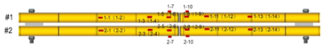 |
| V | Both were complete bamboo specimens | 5 | 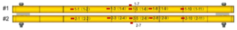 |
| Type I | Type II | ||||||||
|---|---|---|---|---|---|---|---|---|---|
| Specimen | Pmax/MPa | Fmax/kN | Flexural Strength /MPa | Modulus /GPa | Specimen | Pmax/MPa | Fmax/kN | Flexural Strength /MPa | Modulus /GPa |
| Mean | 54.48 | 0.73 | 32.49 | 9.58 | Mean | 143.89 | 2.02 | 80.20 | 11.78 |
| SDV | 12.28 | 0.22 | 7.22 | 1.66 | SDV | 38.81 | 0.32 | 27.62 | 3.39 |
| COV | 22.53% | 29.66% | 22.21% | 17.38% | COV | 26.97% | 15.75% | 34.44% | 28.77% |
| Specimen | Stress (MPa) | Maximum Load (F/kN) | Displacement X/mm | Stiffness/N·mm−1 | |
|---|---|---|---|---|---|
| TA Type III | Mean | 160.81 | 2.93 | 50.88 | 83.07 |
| SDV | 20.55 | 0.33 | 10.66 | 10.47 | |
| COV | 12.78% | 11.20% | 20.94% | 12.61% | |
| TB Type IV | Mean | 120.86 | 1.62 | 43.12 | 42.36 |
| SDV | 15.37 | 0.29 | 11.92 | 7.49 | |
| COV | 12.71% | 17.94% | 27.64% | 17.69% | |
| TC Type V | Mean | 211.8 | 3.70 | 65.73 | 96.25 |
| SDV | 24.76 | 0.64 | 7.70 | 16.96 | |
| COV | 11.70% | 17.21% | 11.71% | 17.62% | |
Publisher’s Note: MDPI stays neutral with regard to jurisdictional claims in published maps and institutional affiliations. |
© 2022 by the authors. Licensee MDPI, Basel, Switzerland. This article is an open access article distributed under the terms and conditions of the Creative Commons Attribution (CC BY) license (https://creativecommons.org/licenses/by/4.0/).
Share and Cite
Zhou, H.; Yan, Y.; Su, N.; Fang, C.; Liu, H.; Zhang, X.; Fei, B.; Ma, X. Flexural Properties of Multiple Bamboo Beams with Connection Joints. Forests 2022, 13, 1851. https://doi.org/10.3390/f13111851
Zhou H, Yan Y, Su N, Fang C, Liu H, Zhang X, Fei B, Ma X. Flexural Properties of Multiple Bamboo Beams with Connection Joints. Forests. 2022; 13(11):1851. https://doi.org/10.3390/f13111851
Chicago/Turabian StyleZhou, Hui, Yan Yan, Na Su, Changhua Fang, Huanrong Liu, Xiubiao Zhang, Benhua Fei, and Xinxin Ma. 2022. "Flexural Properties of Multiple Bamboo Beams with Connection Joints" Forests 13, no. 11: 1851. https://doi.org/10.3390/f13111851