1. Introduction
Chinese traditional houses are the carriers of national survival wisdom, construction skills and aesthetic consciousness, which also became China’s valuable resource of cultural heritage. Some traditional wood-structure houses remain preserved in villages and towns of Southwest China. Due to frequent earthquakes, environmental erosion, lack of regular maintenance and other causes, their main structures have been damaged to various degrees. To preserve these precious traditional wood-structure houses for long enough, it is urgent to study the seismic performance and reinforcement technology of the specific kind for their structures.
According to the survey data on earthquake damages, in some high-intensity areas in Southwest China, the tenon and mortise joints of wood-structure houses were pulled out and removed, and even the wood roof-frame had been tilted as a whole and collapsed [
1,
2,
3,
4,
5]. This phenomenon is mainly caused by the shrinkage and extrusion deformation of the tenon joint causing serious degradation in the mechanical properties of the joint, which eventually leads to the destruction of the entire structure [
6,
7,
8,
9].
Joints are the basic and key point of wooden structures, because they carry loads between the various parts of the structure, they maintain the structure and ensure the unity and integrity of the wooden products during its use [
10]. Researchers have focused on the strength of mortise and tenon joints, among which Kamperidou et al. and Kamboj G et al. successively used adhesives to strengthen some furniture joints and found that the stiffness of the joints was greatly improved [
11,
12]. Numerous scholars have put forward some reinforcement measures for the joints and carried out relevant research. Their test results showed that the diagonal brace reinforcement could provide greater stiffness for the joints but is very detrimental to the tenon pull-out resistance [
13]. Other reinforcement methods, such as tinplate, carbon fiber cloths, steel members and self-tapping screws are also proven to be capable of certainly improving the stiffness of wood joints and effectively reduce the tenon-pulling; but, the energy dissipation of the joints has not been significantly increased when the structures experienced small deformation [
14,
15,
16,
17,
18,
19]. Besides, Pan et al. [
20] found that the reinforcement of steel members enhanced the stiffness of wood joints and the internal force of some adjacent members, which is prone to causing the tenon failure of adjacent joints, while the dampers could reduce the vibration response of the structure without increasing the stiffness of these joints.
To improve the energy dissipation of wood joints, researchers have consecutively developed a series of damping devices. Zou et al. [
21] proposed a new type of angular displacement damper applicable for wood-frame buildings in villages and towns. Their tests verified that the new damper presented good deformation ability, effective fatigue resistance and certain energy dissipation capacity. Lu et al. [
22,
23] sequentially proposed the technologies of an arc-shaped energy dissipator and mortise-embedded energy dissipator to strengthen the performance of mortise and tenon joints, conducted experimental research on the seismic performance of these joints, and studied the impacts of the above energy dissipators with different parameters (radius, thickness and number of layers) on the seismic performance indexes of mortise and tenon joints. Gao et al. [
24] conducted a shaking table test on a bucket type of wood-structure with fan-shaped viscoelastic dampers. Then, Nie et al. [
25] investigated the influences of the above fan-shaped viscoelastic dampers on the seismic performance of dovetail joints with different levels of tightness, and summarized that these dampers could improve the energy dissipation ability, stiffness and bearing capacity of the wood-structure. Xue et al. [
26,
27,
28] sequentially proposed innovative friction dampers and “shape memory alloy” (SMA) steel-wire dampers to strengthen mortise and tenon joints. The pseudo-static test results revealed that these two types of dampers could both reduce the amount of tenon pulling, improve the ultimate bearing capacity and initial stiffness of the joints, and enable the energy dissipation to increase significantly even under small deformations.
Although the above scholars have proposed new damping devices for wood-structure joints and implemented corresponding test research on their performances, the analysis of their test results indicate that most of these reinforcement devices would encounter the following problems: Firstly, the majority of the joint type dampers exhibited low energy dissipation before the joint angle reached 0.05 rad, which only became significant for larger structural deformation. However, the “technical standard for maintenance and strengthening of historic timber building” [
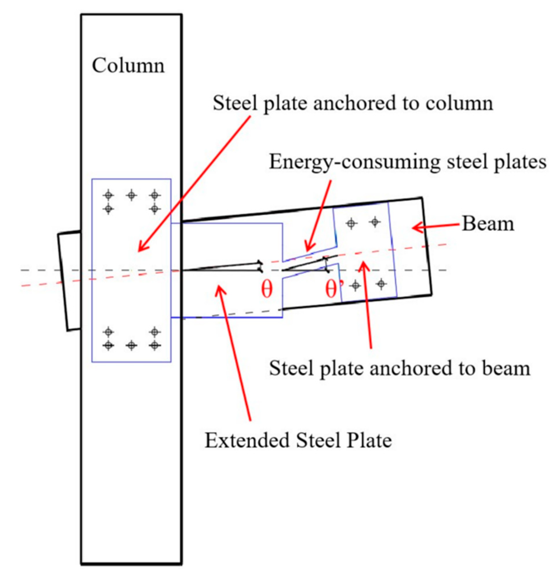
29] stipulates that the inter-story displacement angles of wood frames under rare earthquakes must be limited to 1/30 (0.033 rad), which requires the damper to have good energy dissipation capacity even under small angle deformation of the structure. Secondly, some reinforcement devices (such as innovative friction dampers and SMA reinforcements) are mounted at the angles of the wood-structure joints, which achieved a significant damper energy dissipation of the structure even under small deformation, but it certainly compromised the original style of the wood-structure building. In view of the above concerns, this paper puts forward a technology of innovative metal damper reinforcing mortise and tenon joints of wood-structures, which presents two major advantages as follows: First, with the help of extended steel plate, the angular deformation of dampers’ energy dissipation section increased (the joint angle shown in
Figure 1 is θ and the angle of the energy dissipation section is enlarged to θ’); resultantly, the damper could dissipate as much energy as possible within the limited deformation range of the inter-story displacement angle [
30]. Second, the two ends of the damper were fixed to the sides of the beam and column under the effect of self-tapping screws. As a result, the damper could be effectively hidden simply by keeping the color of the damper similar to that of the wood components in reducing its interference to the original architectural style of the wood-structure.
Through the quasi-static test, the changes to seismic performances of three types of mortise and tenon joints before and after reinforcement were compared, respectively. It was demonstrated that the innovative metal dampers proposed in this paper could not only improve the bearing capacity of the joints, but also greatly elevate their energy dissipation when the structure encountered small deformations, which might provide a reference for the practical reinforcements of traditional wood-structure houses.
The motive and purpose of this paper is to propose a new metal device to enhance the load-bearing capacity and energy dissipation capacity of mortise and tenon joints in wooden houses. This device can effectively reduce the damage of wooden structure or wooden furniture under vibration load and prolong its service life.
3. Test Phenomenon
3.1. Test Phenomena before and after Straight Tenons’ Reinforcement
For the unreinforced test piece ZTS0, there is a “creak” sound during the whole test loading process. When loading near the amplitude, the sound interval is long and the volume is large, while when unloading, it is continuously compact and the volume is small. At the initial stage of loading (vertical loading displacement of 5 mm and 10 mm), the extrusion deformation of tenon and mortise is not obvious, but the gap between tenon and mortise can be observed to be compacted. As the loading displacement increases step-by-step, not only does mutual extrusion occur at the contact edge between the tenon and the mortise, but relative sliding between them occurs, which is more significant. After the test, the tenon is pulled out about 4 mm from its initial position, and its top and bottom surfaces leave obvious local indentation, and this part becomes very smooth due to sliding friction.
For the strengthened sample ZTS1, the squeezing and sliding friction between the tenon and the mortise, and the friction between the steel plate and the wood beam on both sides, led to the sound in many places during the whole loading, and the “dong dong” sound gradually dominated in the subsequent loading. As for the damper, during the whole loading process, the steel plate of the boom section is firmly connected with the column, and no vertical displacement is observed. There is no relative slip between the beam and the anchor steel plate. The deflection effect of the energy dissipation section is obvious with the increase of the angle (see
Figure 6). After the final level of loading (25 mm), a visible transverse crack appeared at the edge of the energy-dissipation steel plate inside the beam (see
Figure 7).
3.2. Test Phenomena before and after Penetrated Tenons’ Reinforcement
The phenomenon in the early test of the unreinforced sample TJS0 is similar to that of the ZTS0. Except, there is a “creaking” sound in each stage of loading and there is a mutual extrusion deformation between the tenon and the mortise; it is also obvious that the tenon can be pulled out step-by-step during the reverse loading due to the existence of steps inside the tenon. The tenon pulled out during the unloading process cannot be completely recovered, and the residual tenon pulling value increases step-by-step.
For the reinforced TJS1, the weak sound of wood tearing can be heard during the first stage loading and the development and extension of dry shrinkage cracks on the column can be observed. The main test phenomenon of the damper is the same as that of ZTS1, except that the upper and lower edges of the energy dissipation section of the inner damper locally bulge outward during the fifth stage (25 mm) loading and are leveled during unloading.
3.3. Test Phenomena before and after Dovetail Tenons’ Reinforcement
Due to the shortest dovetail tenon, the embedded compression effect is the weakest under the same angle. In addition, the large joint gap leads to no sound during the first two stages of loading of the unreinforced YWS0. After that, there is a “dong dong” sound during the forward loading and no-reverse loading at each stage. It is observed that the stopper moves outward with the tenon during the downward loading, and the relative sliding and extrusion effect between the top surface of the tenon and the stopper is small.
For the reinforced sample YWS1, the test phenomenon is roughly the same as that of the other two reinforced samples, mainly with the following differences: there are many small dry shrinkage cracks on the wood column, and the width of the dry shrinkage cracks near the wood-fiber tearing-sound sockets increases step-by-step during the loading, and at the same time, it can be observed that ash dust is ejected from the joints. Starting from the third stage (15 mm), the stopper at the upper part of the tenon is repeatedly pulled out and jacked in with the rotation of the beam: the later the stopper is loaded, the more obvious the stopper movement is. The energy dissipation sections of dampers on both sides are slightly bent out of the plane from loading to the end of the test, and small cracks are found at the upper and lower edges.
4. Test Results and Discussion
4.1. Analysis of Moment-Rotation Hysteresis Curve of Joints
This paper specifies that the extension direction of the actuator is positive, and the retraction direction is negative. In the loading test, it is found that only the mortise and mortise are plastic extruded, and the column and beam are almost free of bending deformation. After the test, the beam and column are basically intact, so the sampled joint’s bending moment M and rotation angle θ can be calculated from Equations (1) and (2), respectively.
where F is the reaction force measured at the loading point; L is the distance from reaction force to column edge; and δ is the vertical displacement at the loading point.
The moment-rotation hysteresis curve of each sample is shown in
Figure 8. The analysis of three types of joints before and after reinforcement is as follows:
(1) Straight tenon. The positive and negative loading hysteretic curves of the joint samples before and after reinforcement are basically symmetrical, and the “pinch” effect of the sample ZTS1 is slower than that of ZTS0, indicating that the metallic damper reduces the relative slip between mortise and mortise during the loading process, and increases the energy dissipation of the joint. The hysteresis loop areas of the second and third cycles of loading at the same level are close to, but less than, the first cycle, which is mainly due to the stiffness degradation caused by the plastic extrusion of the tenon and mortise during the first cycle of loading. It can also be seen from the figure that the curve of ZTS1 is similar to that of ZTS0 under the first and second stage loadings, which indicates that the internal clearance of ZTS1 is large, while the tenon and mortise are not squeezed with each other when the angle deformation is small. At this time, the bending moment is only provided by the damper. From the change of reaction force at the loading point, the bending moments of ZTS0 and ZTS1 grow with the increase in rotation angles. The growth rate of the former is significantly lower than that of the latter. After the reinforcement, the bearing capacity of the joint is significantly improved. Within the rotation range shown in the figure, the maximum bending moment of the ZTS1 joint is 6.4 KN·m, about 2.2 times that of ZTS0.
(2) Penetrated tenon. The unreinforced TJS0’s forward and reverse loading hysteresis curves are asymmetric, which is manifested in that the reverse loading’s hysteresis loop area and bearing capacity are slightly larger than those of the forward loading, because the step tenon structure is asymmetric, which leads to the difference between the mechanical mechanisms of forward and reverse rotations [
33]. The relative symmetry of TJS1 curve is due to the fact that the proportion of the reaction provided by the damper with the same forward and reverse mechanical properties than the wood joint itself means that the difference between the forward and reverse directions of the whole figure is reduced. The curve “pinching” effect of the through mortise joint after reinforcement is greatly reduced, but not as good as that of the straight mortise joint after reinforcement, indicating that the slip of the through mortise joint before and after reinforcement is large. The reaction force at the loading position of TJS1 increases significantly, and the bending moment reaches the maximum value of 5.5 KN·m near the angle of 0.05 rad, while the maximum value of unreinforced TJS0 in the rotation section shown in the figure is 1.9 KN·m.
Dovetail tenon. Among the three types of unreinforced mortise and tenon joints, YWS0 exerted the lightest “pinch” effect. This is because the dovetail tenon enhances the extrusion and friction between its sides and the mortise, effectively limiting the slip of their joint. The specimen was disassembled after the test, and it was found that there was a large amount of wood chips in the mortise, the mortise and the side of the mortise were seriously worn (see
Figure 9), and the waste heat after friction was obviously felt. The enhanced YWS1 also exerts a slight “pinch” effect, which is lighter than the other two types of reinforced joints, and the overall inclination of the curve turned out to be the smallest. From the change of reaction force at the loading point, the unreinforced YWS0 bending moment value is small and the growth rate is slow. Under each level of loading, the reaction force of the straight tenon and penetrated tenon is significantly greater than that of the dovetail tenon, because the reaction force is mainly determined by the internal embedded pressure of the joint, while the dovetail tenon is only half the length of the other two types of tenon, and its internal embedded pressure is the smallest. In addition, the processing technology level and wood discreteness also have a certain impact on the reaction force at the loading point. The YWS1 reaction force of the reinforced sample is significantly increased, but still significantly less under the forward loading than under the reverse loading. It is observed that the cork at the upper part of the tenon is pulled out to the outside and the internal gap of the joint becomes larger when loading downward, and the cork is pressed inward when loading upward, so the reaction force increases faster under the reverse loading.
4.2. Skeleton Curve Analysis
We connected the extreme points obtained by loading at all levels to obtain the skeleton curve of bending moment and rotation angle of three types of mortise and tenon joints before and after reinforcement, as shown in
Figure 10.
From the analysis of curve change, the skeleton curve of the unreinforced joint sample rises gradually and there is no falling section, indicating that the three types of mortise have good deformation capacity. The bending moments of ZTS0 and TJS0 both grow rapidly with the increase of the rotation angle, while that of YWS0 hardly grows after the rotation angle reaches 0.01 rad. This is because the bearing capacity of straight tenon and penetrated tenon is mainly provided by the embedded pressure inside the joint. The larger the rotation angle is, the stronger the embedded pressure is, while the dovetail tenon is mainly borne by the internal friction, and the friction does not change significantly with the rotation angle. In addition, the slope of the skeleton curve of the unreinforced joint decreases gradually, because the plastic extrusion deformation between the mortise and tenon increases with the increase of the angle, resulting in the attenuation of the joint stiffness, and the slope of the whole curve decreases step-by-step.
The skeleton curve of the strengthened joints ZTS1, TJS1 and YWS1 under forward and reverse loadings is relatively steep on the whole, and the damper has an obvious effect on improving the bearing capacity of each joint. At the initial stage of loading, the slope of the skeleton curve of the damper mounted sample ZTS1 first decreases and then increases sharply, which is the transition from the joint compaction to the mortise and tenon compression, reflecting the large internal clearance of ZTS1: the slope of the enhanced TJS1 and YWS1 skeleton curves decreases gradually from the beginning of loading to the end, indicating that the internal gap of the joints is small.
4.3. Stiffness-Degradation Curve Analysis
The stiffness of the wood joint is closely related to the size, clearance and wood properties of the mortise and tenon. With the increase in the loading displacement, the embedded pressure and friction between the mortise and the mortise will increase, which will cause the stiffness degradation. The positive and negative secant stiffness of the sample under various levels of loading is calculated according to Equation (3).
where M
i is the peak bending moment in the first positive (negative) cycle of the i-stage displacement loading; θ
i is the angle value corresponding to M
i.
We calculated the stiffness of the sample at all angles according to the above formula, and drew the degradation curve into
Figure 11:
The average stiffness values of unstiffened joints ZTS0, TJS0 and YWS0 are all as low as 61.7 KN·m/rad, 55.9 KN·m/rad and 40.9 KN·m/rad, respectively. The stiffness decreases gradually, and the degradation rate becomes slow under forward and reverse loadings. From the curve change law, it can be seen that the stiffness of each gradient of the joint under forward loading is: ZTS0 > TJS0 > YWS0, and that under reverse loading is: TJS0 > ZTS0 > YWS0. It can be seen that the stiffness of the TJS0 joint under forward loading is less than that under reverse loading, which is the difference in clockwise and counterclockwise mechanical properties caused by the shape of the tenon ladder.
The joint stiffness of strengthened ZTS1, TJS1 and YWS1 is greatly improved under both forward and reverse loading, and their average values are 120.4 KN·m/rad, 168.7 KN·m/rad and 118.6 KN·m/rad, respectively. In general, the stiffness of each joint deteriorates with the increase in the rotation angle, and the stiffness of ZTS1 decreases first and then increases, which is due to the large internal clearance. The TJS1 stiffness of the sample decreases step-by-step, and the reverse stiffness is slightly greater than the forward stiffness under all levels of loading. The stiffness degradation curve of the YWS1 sample is seriously asymmetric and the reverse stiffness is always greater than the positive one. This is because the cork at the top of the dovetail tenon moves outward during positive loading, resulting in low joint loosening stiffness, while the cork squeezes inward during reverse loading, resulting in high joint stiffness.
4.4. Energy-Dissipation Capacity Analysis
In the low-cycle reciprocating test, the hysteresis loop of the wood joint sample is shown in
Figure 12. Through the analysis of the hysteresis loop, the equivalent viscous damping coefficient he of the sample can be obtained, which can reflect the energy dissipation capacity of the joint. Its specific calculative equation [
34,
35] is as follows:
where the numerator is the area of the hysteresis loop (the shaded part in
Figure 12). This paper applies the area of the first cycle of each stage, and the denominator bracket part is the sum areas of the triangles CEO and DFO.
The variation curve of the equivalent viscous damping coefficient he of each joint with the rotation angle is shown in
Figure 13.
In general, the energy dissipation capacity of all unreinforced joints decreases with the increase of the angle, because the energy dissipation of joints mainly depends on the friction between the tenon and the socket and the compression deformation. In the process of repeated loading, the friction surface between the tenon and the socket is gradually smooth, and the plastic deformation caused by the compression is gradually reduced. From the curve comparison, it can be seen that the equivalent viscous damping coefficient of the dovetail joint in the unreinforced joint is the largest, and the reason can be analyzed from the calculative equation: First, as for the molecular term, although the interaction between the top, bottom and the mortise during loading is reduced due to the halving of the length of dovetail joint, the two sides and the mortise will also be squeezed and rubbed to consume energy. In fact, the difference between the total energy dissipation of each stage of the dovetail tenon (numerator in Equation (4)) and the straight tenon and step tenon is small, which can be verified by the calculation results of the hysteretic loop area of each stage of the three joints. Secondly, from the denominator, it can be seen from the previous hysteresis curve that the bearing capacity of dovetail joints with the same angle is relatively small, so its elastic strain energy (denominator in Equation (4)) is the lowest.
The average equivalent viscous damping coefficients of the unreinforced samples ZTS0 and TJS0 are 0.14 and 0.15, respectively, and those of the damper mounted samples ZTS1 and TJS1 are 0.23 and 0.18, respectively, indicating that the energy dissipation capacity of the joints of the mortise and through mortise samples is significantly increased and the lifting range of the mortise is more significant. The equivalent viscous damping coefficient of YWS1 joint is slightly lower than that of unstiffened YWS0, because the growth rate of joint energy dissipation after mounting the damper is less than that of elastic strain energy. This means that to improve the equivalent viscous damping coefficient of dovetail joint, it is necessary to design a damper suitable for the stiffness, and control the increase range of joint strain energy while increasing the joint energy dissipation.
Furthermore, another evaluation index of the energy dissipation capacity of the joint is the staged energy dissipation. In this paper, the average value of the area enclosed by three complete hysteretic curves at each stage is taken as the stage energy dissipation of the joint. The calculation results are shown in the curve in
Figure 14. It can be seen from the figure that the energy dissipation curves of the unreinforced straight tenon, step tenon and dovetail tenon almost coincide, and the energy dissipation of three joint stage is low, and the maximum value is close to 0.07 KN·m. After mounting the metallic damper, the energy dissipation of each stage of each joint increases significantly, and the maximum energy dissipation in the ZTS1 stage reaches 0.33 KN·m.
4.5. Tenon’s Pulling Amount Analysis
Under the low-cycle round-trip load, the tenon is repeatedly pulled out and reset from the mortise, and the horizontal displacement of the tenon relative to the initial position after each level of loading is called the residual tenon pulling amount. Research [
36] shows that the tenon pulling amount will not only affect the bearing capacity of the joint, but also lead to the tenon breaking of the joint and the collapse of the building in serious cases. In the test, the residual tenon pulling amount of each test piece measured by the displacement meter is shown in
Figure 15. From the figure, it can be seen that the residual tenon pulling amount of each joint test piece increases with the increase of the angle. The tenon pulling amount of the step tenon at the same angle is the largest, followed by the straight tenon, and the dovetail tenon is the smallest. The maximum residual pulling amounts of straight tenon, penetrated tenon and dovetail tenon before reinforcement are 4.5 mm, 8.9 mm and 3.9 mm, respectively. The corresponding tenon pulling values after reinforcement are 0.9 mm, 3.3 mm and 0.54 mm, respectively, indicating that the damper can effectively control the residual tenon pulling of the tenon joint.


