Article

A Case Study on the Energy Capacity of a Flexible Rockfall Barrier in Resisting Landslide Debris

1
School of Civil Engineering, Southwest Jiaotong University, Chengdu 610000, China
2
Sichuan OST Slope Protection Engineering Co., Ltd., Chengdu 610000, China
*
Author to whom correspondence should be addressed.
Forests 2022, 13(9), 1384; https://doi.org/10.3390/f13091384
Submission received: 22 July 2022 / Revised: 26 August 2022 / Accepted: 29 August 2022 / Published: 30 August 2022
(This article belongs to the Special Issue Landslides in Forests around the World: Causes and Mitigation)

Abstract

:
Landslides frequently occur in forest areas with a steep hillside, especially when severely disturbed by human activities. After sustained heavy rainfall, a landslide occurred near the Tianwan tunnel entrance of the Chongqing-Huaihua railway in China. Fortunately, the landslide debris was successfully intercepted by a flexible barrier originally installed to stop rockfalls, which is, to date, the first publicly reported case of landslide debris having been successfully intercepted by a flexible barrier without any damage, in mainland of China. A field investigation was first conducted, and then a back analysis of the landslide mobility and the interaction between the landslide and the flexible barrier was carried out. The back analysis showed that the impact energy was three-times larger than the rated energy capacity of the flexible barrier. It also showed that the elongation of the brake rings and the deflection of the flexible barrier from the numerical simulation was comparable to that from the field measurements. The fact that these brake rings were not elongated to their limit indicated that the capacity of the flexible barrier still had a surplus. Finally, to investigate the maximum energy capacity of a flexible rockfall barrier in resisting landslide debris, parametric analyses of a flexible barrier impacted by landslide debris with different impact energies and velocities were carried out using a coupled ALE-FEM modeling technique. The results showed that the flexible barrier dissipated less than 40% of the total energy of the landslide debris. With an increase of impact energy, the energy dissipation ratio of the flexible barrier decreased linearly. The maximum energy capacity of a flexible rockfall barrier in resisting landslide debris is four-times that of resisting a rockfall.

1. Introduction

Forests play an important role in the ecological environment, and can effectively improve the stability of slopes and inhibit the occurrence of geological disasters, such as debris flows and landslides [1,2,3,4]. However, with the rapid development of transport infrastructure in the western mountainous regions of China, forests in these areas have been severely disturbed, resulting in the frequent occurrence of slope geological hazards, such as landslides, debris flows, and rockfalls (Figure 1). To make matters worse, destructive earthquakes occur frequently in this area, such as the M8.0 Wenchuan earthquake, M7.0 Lushan earthquake, etc. The risk of slope geological hazards after earthquakes in this regions is heightened significantly [5,6]. In addition to traditional rigid barriers [7], such as rigid walls, reinforced dams, etc., flexible barriers, which benefit from rapid construction, easy maintenance, environmental sustainability, and economic competitiveness, are increasingly being considered as a viable measure to deal with slope geological hazards [8]. It can be seen that flexible barriers are capable and help in the implementation of the main sustainable development goals (SDG) employed by the United Nations (UN) Agenda.
According to the characteristics of flexible barriers, flexible barriers can be categorized into three types: active flexible barriers, passive flexible barriers, and attenuator systems [10]. Active flexible barriers consist of three basic elements; namely, anchors, support cables, and nets, and are used to press the soil from the moment of installation, thus preventing instabilities [11]. Passive flexible barriers are made of a cable net, structural steel posts, and special connecting components, and are used to intercept and stop blocks of rock from bouncing, rolling, and sliding along a slope [12,13,14]. Attenuator systems are structures made of flexible wire netting, designed to reduce the kinetic energy of a rockfall and guide its trajectory [15,16].
Over the past years, after the flexible barriers that were originally installed to intercept rockfalls were found to have successfully stopped and contained landslide debris [17,18], researchers and engineers have become interested in studying and adopting flexible barriers to mitigate debris flow.
Large-scale tests were conducted to investigate the response of flexible barriers to debris flows. Usually, a varied instrumentation was used to record flow velocities, forces on cable ropes, debris flow character, and barrier response [19,20,21,22]. A full-scale test site was also built by WSL in Illgraben, one of the most active debris flow torrents in the Swiss Alps, and V-Barrier systems without any posts were developed and installed in the channel [7]. Small-scale laboratory tests were also carried out to parametrically study the performance of flexible barriers subjected to debris impacts, such as the influence of mesh size, and the gap between the lower barrier edge and the channel’s floor [23,24,25,26,27]. Numerical tools and methods, divided into static simulation and dynamic simulation, have been proposed and developed to model flexible barriers under debris impacts. In static models, impact pressures are applied quasi-statically. Due to the large-sliding, large-nonlinear characteristic of flexible barriers, specially developed software, namely FARO [28] and NIDA-MNN [29], are available for capturing the response of flexible barriers. In dynamic models, coupled methods are adopted to simulate the interaction between flexible barriers and debris flows. Useful coupled methods include CFD-DEM [30,31], FEM-DEM-LBM [32], ALE-FEM [33,34,35], DEM-MPM [36,37], etc.
Benefiting from the above studies, two design methods, namely the force approach and energy approach, have been proposed to design flexible barriers against debris flows. The force approach is the traditional method in the design of structures, which means the structure members are checked and optimized after calculating the internal forces of the structure under specific loads. The core of the force approach lies in the determination of the load, including the distribution and magnitude of the load. Thus, a load model to calculate the loads acting on a flexible barrier has been a research focus [20,22,26,28,38]. However, the value of the dynamic pressure coefficient is empirical and varies greatly, from 0.6 to 5.5 [39]. The energy approach, similar to the design of flexible rockfall barriers, means the barrier is only required to dissipate a certain amount of impact energy [40,41,42]. The design method was proposed by Wartmann and Salzmann [43] and described in detail by Roth et al. [44]. Compared to the force approach, the energy approach is much simpler and was also adopted in guidelines in Hong Kong [45]. Due to a lack of knowledge, a scaling factor of not exceeding 75% is adopted to reduce the energy capacity of a flexible barrier established by full-scale rockfall tests, in the case of resisting debris flows. However, Song pointed out that less than 10% of the debris impact energy was absorbed by the flexible barrier, and over 90% of the energy was dissipated through the internal and boundary shearing [46].
Due to the difference in material properties and load modes, the energy transformation and dissipation characteristics of a flexible barrier will be significantly different in resisting rockfalls and landslide debris, and it is not sufficient to evaluate the capacity of a flexible barrier in resisting landslide debris just by the ratio of energy dissipated by the flexible barrier, as mentioned above. To date, the technical and scientific knowledge of the assessment of a flexible barrier subjected to a rockfall is relatively mature, and assessment documents have been published and accepted widely [47]. Several test sites have also been built, and a large number of tests have been conducted [40,48,49]. For evaluating the capacity of a flexible barrier established using a full-scale rockfall test in the case of resisting landslide debris conveniently, it is worth revealing the relationship between the energy capacity of a flexible barrier in resisting rockfalls and debris.
In this paper, a field investigation of landslide debris successfully intercepted by a flexible barrier was first conducted. Then, a back analysis of the landslide mobility and the interaction between the landslide and the flexible barrier were carried out. The elongation of the brake rings and deflection of the flexible barrier from field measurements were used to verify the numerical simulation. Finally, parametric analyses of the flexible barrier impacted by landslide debris with different impact energies and velocities were carried out, to reveal its ultimate energy capacity.

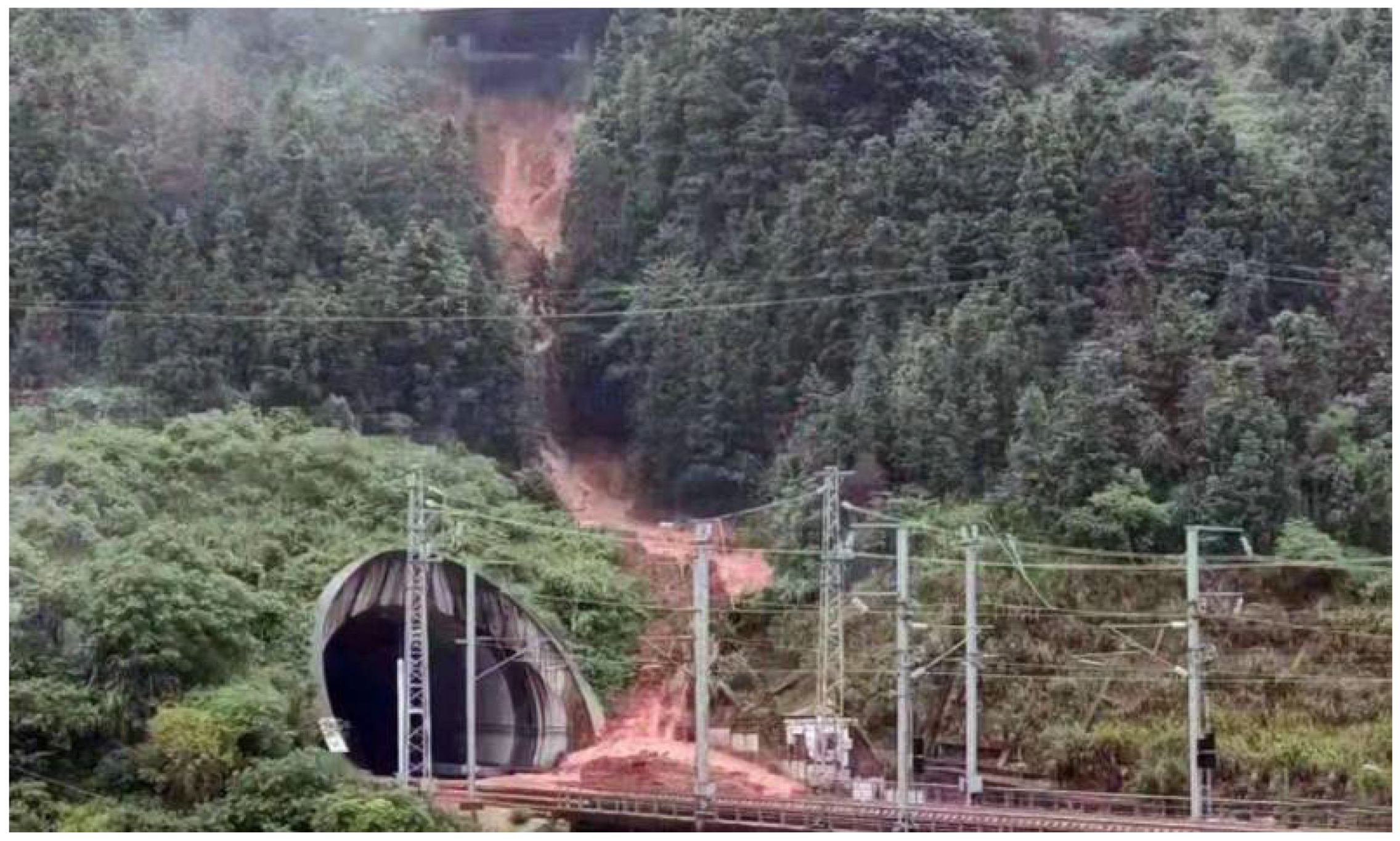
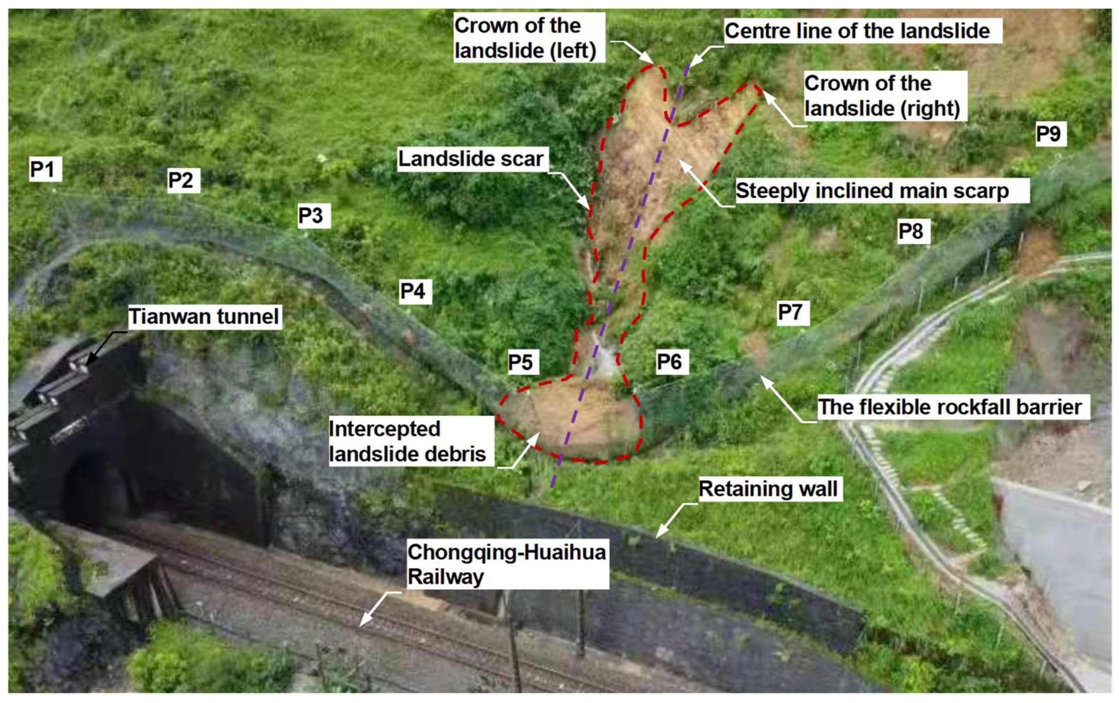
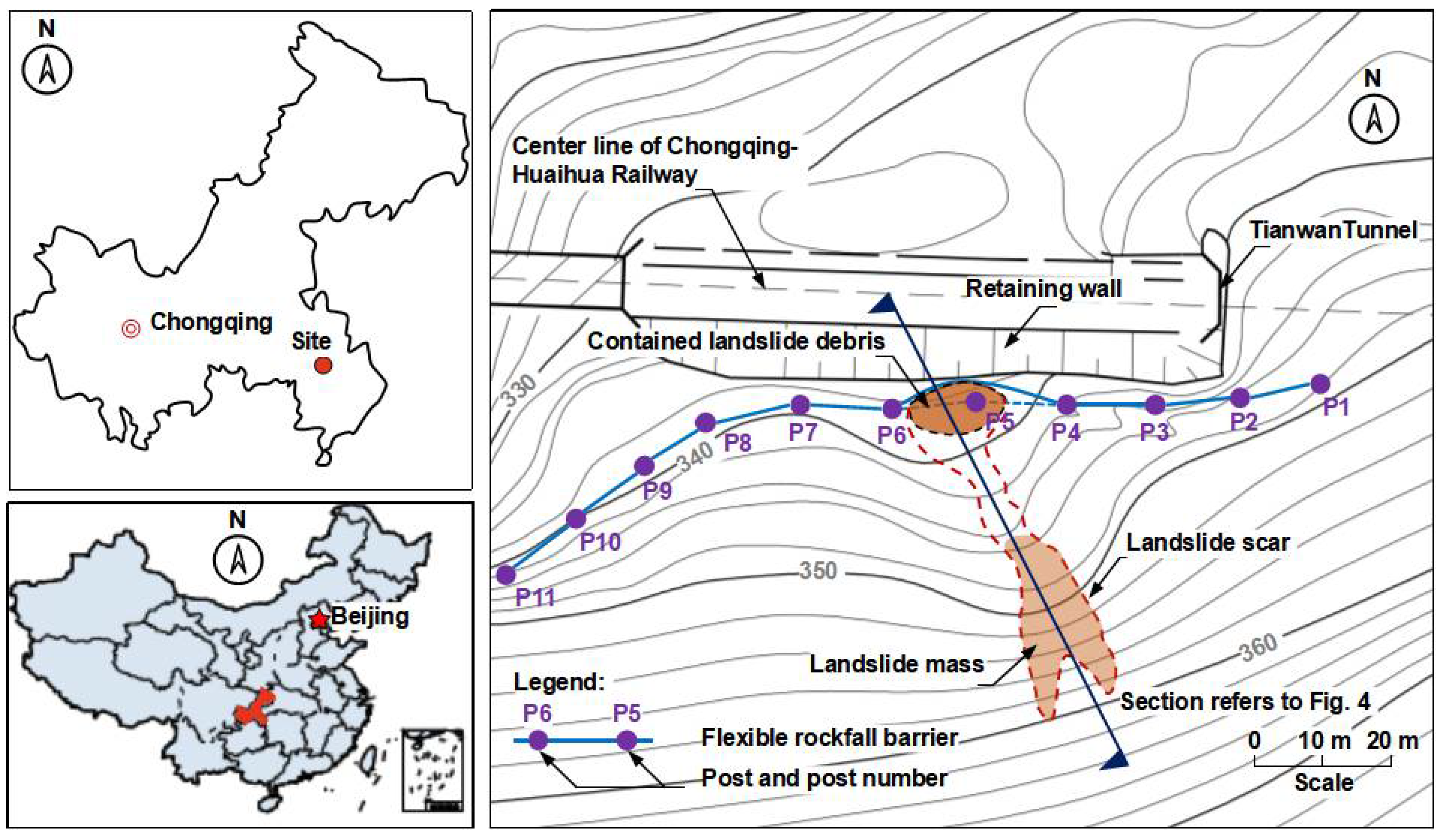
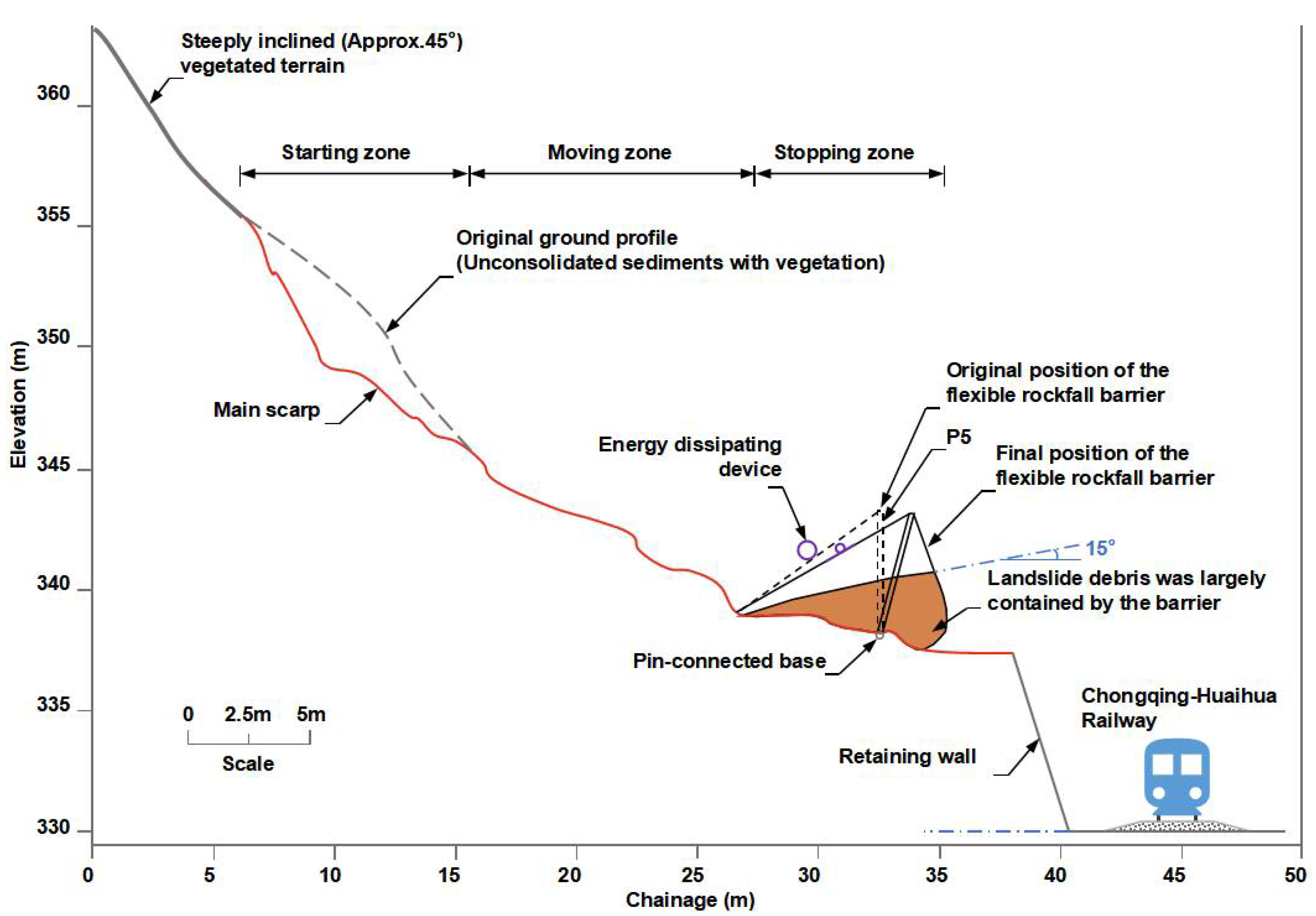
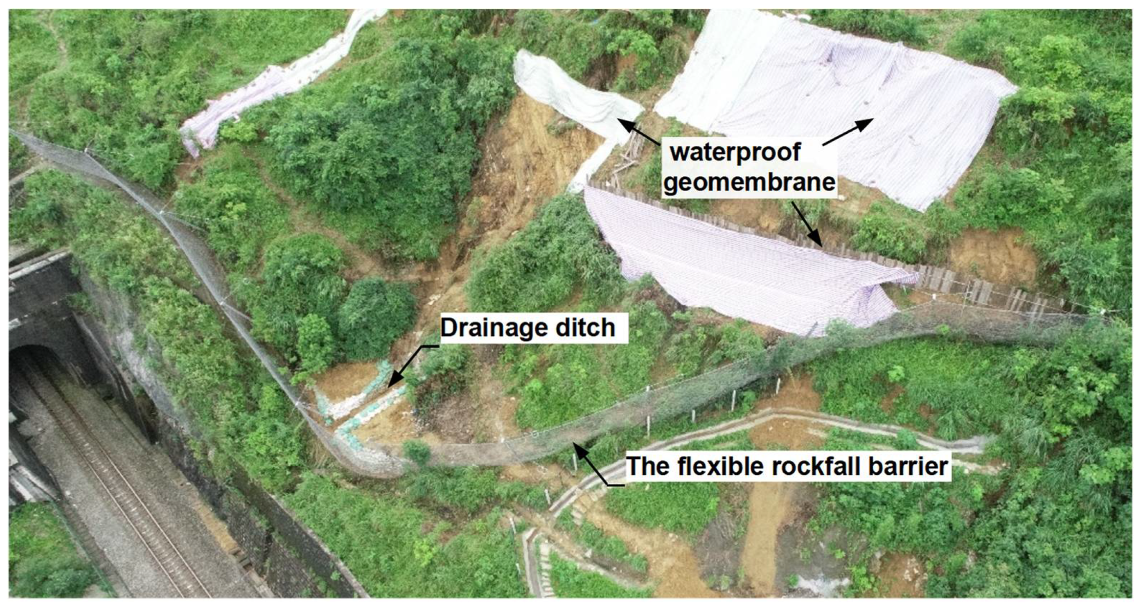
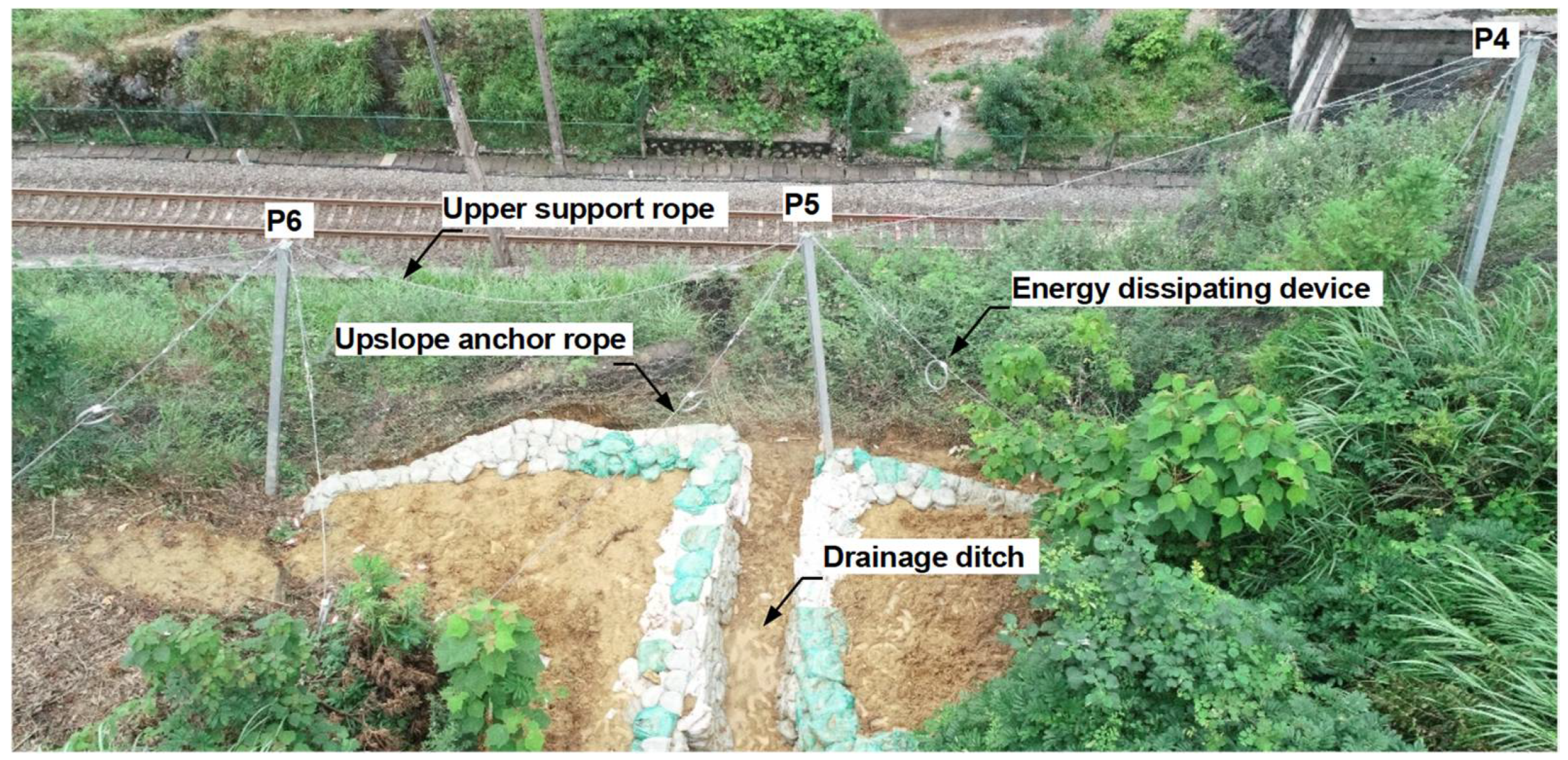
2. Open Hillside Landslide in Chongqing, China

2.1. Field Investigation

The open hillside landslide occurred on terrain above a cut soil slope, which was formed to become a tunnel entrance of the Chongqing-Huaihua railway (Figure 2). A retaining wall was constructed to increase the stability of the slope. A flexible barrier with a total length of about 100 m was installed behind the retaining wall, to mitigate rockfalls from the hillside. The type of flexible barrier is a RXI-075, which is rated with an energy of 750 kJ. The flexible barrier is divided into ten functional modules by eleven steel posts, and the spacing of the adjacent two posts is 10 m. The height of the posts is 5 m. The posts were made of H-shape steel, with a section of 150 × 150 × 6 × 10 mm, and connected to foundations by pins. The main nets were composed of 300-mm opening rings formed by nine windings of 3-mm diameter steel wires. A twisted hexagonal wire mesh with openings of about 60 mm was attached to the ring nets, to capture small rock pieces.
The landslide occurred on the morning of 13 June 2020, due to heavy rainfall for days. After the finding of the landslide, an investigation and maintenance were carried out immediately. A realistic 3D model of the terrain was built using an DJI unmanned aerial vehicle (UAV) combined with 3D real-scene modeling software named ContextCapture. By comparing the terrain before and after the landslides, the total volume of the landslide was found to be approximately 70 m3, and this was in accordance with the volume measured during maintenance. Figure 3 shows the plan view of the locations of the posts of the whole flexible barrier and the slide area of the landslide. The debris material was almost totally retained by the flexible barrier. No signs were found to show that the debris overflowed the barrier or passed through the net. In addition to the expected elongations of braking rings, rotations of the posts P5 and P6, and the deformation of nets, no failures of the flexible barrier were found, even for post P5, which was directly struck by the debris. In other words, the flexible barrier intercepted the landslide debris very successfully.
The cross-section along the centerline of the landslide is shown in Figure 4. The landslide started on a steeply inclined scarp covered with unconsolidated sediments. The upper portion of the source area comprises vegetated terrain and is steeply inclined (>45°), while the lower portion comprises predominately matrix-supported debris overlying saprolite. The debris was saturated. The stacking angle of the stopped debris was about 15°. The stacking angle did not represent the internal friction angle of the debris, because it was intercepted by the flexible barrier. Obviously, the internal friction angle of the debris was less than 15°.
After the finding of the landslide, multiple measures were adopted to maintain the flexible barrier. Most of the debris material was removed. A drainage ditch along the centerline of the landslide was excavated, to improve the drainage. Several waterproof geomembranes were layered on the top and side of the landslide-affected area, to reduce the infiltration of rainwater into the soil. The elongated braking rings and the impacted nets of the flexible barrier were replaced. The landslide site after maintenance is shown in Figure 5, and the repaired flexible barrier is shown in Figure 6.

2.2. Back-Analysis of the Landslide and Flexible Barrier Interaction

LS-DYNA, which has been successfully used to simulate debris mobility, the dynamic response of flexible barriers impacted by rockfalls, as well as debris and barrier interactions, was adopted to back analyze the interaction of the landslide and the flexible barrier.

2.2.1. Modeling of the Landslide Debris

The elastoplastic Drucker-Prager model [50], which has been successfully adopted to simulate the internal rheology of debris material [33,35], was also used here to simulate the landslide mass. The yield surface is shown in Equation (1):
f = J 2 α I 1 k = 0
where I1 and J2 are the first and second invariants of deviatoric stress tensor, respectively. Material constants α and k are related to the internal friction angle φ and cohesive strength c of the material, and they can be calculated using Equations (2) and (3), respectively:
α = 2 sin φ 3 ( 3 + sin φ )
k = 6 c   cos φ 3 ( 3 + sin φ )
As the landslide mass was saturated and moved like a flow, it was greatly deformed during the movement process. To avoid mesh distortion when simulating large deformation by the Lagrangian method, the arbitrary Lagrangian–Eulerian (ALE) formulation was adopted. In the formulations, the nodes of the computational mesh could be moved with the continuum in normal Lagrangian fashion, or be held fixed in the Eulerian manner or moved in some arbitrarily specified way, to give a continuous rezoning capability. Thus, greater distortions of the continuum could be handled than that allowed by a purely Lagrangian method, with more resolution than that afforded by a purely Eulerian approach.
The key parameters of the landslide mass are summarized in Table 1. The density was measured in the field to be roughly 1800 kg/m3. The shear modulus and bulk modulus were assumed to be 500 kPa and 1000 kPa, respectively. As the stacking angle of the debris intercepted by the flexible barrier was about 15°, which was obviously much bigger than the internal friction angle of the debris. Therefore, the internal friction angle was assumed to be 5°. The friction coefficient between the landslide mass and the slope was assumed to be 0.4, referring to Ref. [35].

2.2.2. Modeling of the Flexible Barrier

To save computational costs, only three functional modules of the flexible barrier, spanning across posts P4 to P7, were built in the model. The barrier is a proprietary product characterized by its ease of repair, as energy dissipating devices are designed as independent and replaceable units to attach to steel-wire ropes. By contacting the manufacturer of the barrier, the structural properties of the different components were confirmed.
The steel-wire ropes were modeled using discrete cable elements, which only have stiffness in axial tension. Beam elements using the plastic kinematic material model were adopted to model the posts. Energy dissipating devices were modeled using plastic tension only, as well as translational spring elements with a tri-linear load-displacement curve. Each steel-wire ring was modeled using sixteen beam elements, with a piecewise elastic-plastic stress-strain curve. The sliding characteristics between rings was explicitly modeled by the general contact algorithm. Seatbelt slip-ring elements, which work as a cable-and-pulley system, were adopted to model the sliding of support ropes on post ends. The loose connections between the edging rings and ropes with shackles were also explicitly modeled using simplified shackles, combined with a guided cable contact algorithm. The configuration and modeling method of the flexible barrier are summarized in Table 2. Generally speaking, the nonlinear and large deformation characteristics of the flexible barrier were effectively simulated in the model.

2.2.3. Modeling of the Interaction

In the model, a special penalty-based coupling algorithm named “Constrained_lagrange_in_solid” was adopted, to recreate the interaction between the landslide and the flexible barrier, as well as the landslide and the slope. The coupling algorithm, essentially, is equivalent to placing a series of springs between the slave surface and the master surface, to limit the penetration. As this command can only represent the interaction between the Lagrangian shell and/or solid structures and the fluids modeled by ALE formulation, additional membranes modeled by shell elements with a null-type material [51] were introduced to cover the steel-wire meshes, to achieve the expected interaction. The introduced membranes could only transmit the interaction force and could not contribute any stiffness to the flexible barrier. It is worth noting that the additional membrane is impermeable, so the landslide mass could not penetrate the barrier. In fact, no signs of penetration of landslide from the flexible barrier were found in the field.
An efficient two-stage coupled modeling technique, developed by the authors [35], was adopted to build a three-dimensional model based on the rebuilt terrain, to investigate the landslide mobility and the landslide and flexible barrier interaction (Figure 7). In the first stage, only the movement of the landslide mass was simulated and the flexible barrier was totally constrained. Thus, a relatively large time step of 5 × 10⁻⁴ was sufficient to ensure the stability of the simulation. When the landslide was about to impact the barrier, the simulation of the first stage was ended and a binary file storing the model information of the last step was created. After removing the additional constraints of the barrier, the full restart technology was applied to initialize the state of the landslide with the binary file. Then, the coupled numerical simulation was launched with resetting to a much smaller time-step of 2 × 10⁻⁵, to ensure the stability of the simulation.

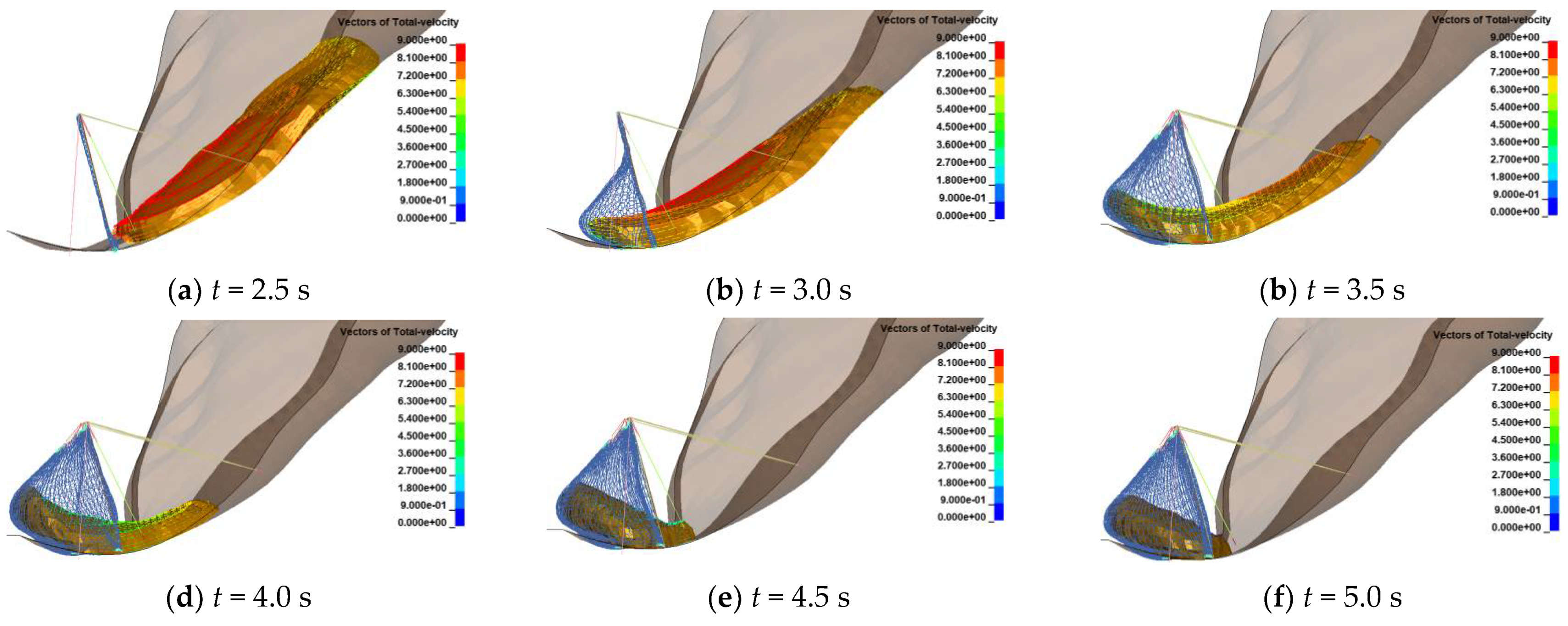
2.3. Mobility of the Landslide

Under gravity, the landslide mass started to slide along the main inclined scarp, from being static till interception by the flexible barrier. Some typical moments of the interception process are shown in Figure 8. The velocity of the landslide at the barrier location and the kinetic energy of the landslide during the sliding are shown in Figure 9. It can be seen that when t = 2.5 s, the landslide impacted the flexible barrier with a maximum frontal velocity of around 9 m/s. After the peak value, the impact velocity dropped to zero within 2 s. The maximum kinetic energy was about 3200 kJ when t = 2.6 s, which is much bigger than the rated energy of the flexible barrier of 750 kJ, assessed using a rockfall impact. The reason for this may lie in the different processes in intercepting a rockfall or debris. The former is only a first impact and the kinetic energy is almost dissipated by the flexible barrier. The latter is successive impacts and the stopped debris may form a “dam” to dissipate the subsequent impact energy. With the development of the interaction, the kinetic energy of the landslide decreased rapidly. The interception process lasted about 2.5 s, and when t = 5.0 s, the landslide was totally stopped. The landslide mass was mainly accumulated in the middle functional span of the flexible barrier, which is generally consistent with the site observations.

2.4. Response of the Flexible Barrier

2.4.1. Internal Forces of the Ropes

The ring nets were directly subjected to the impact of the landslide. Then, the impact force was transmitted to the lower support rope (LSR), upper support rope (USR), and upslope anchor ropes (UAR) in sequence. The internal forces of the ropes are shown in Figure 10. This demonstrates that the lower support rope was the first tensioned among these ropes. When t = 2.6 s, the internal force of the lower support rope increased rapidly, from zero to about 100 kN, which is the ideal activated force of the attached brake rings. Then, with the elongation of the attached brake rings, the internal force increased gently to the maximum value of 113 kN at t = 3.7 s. Then, the internal force decreased to a stable value of 53 kN, when the landslide mass was totally stopped. The internal force history of the upper support rope was almost consistent with the lower support rope. The differences mainly lie in the following two aspects: One is that the upper support rope was tensioned about 0.1 s later than the lower support rope; the other, was that the maximum value of the upper support rope was 108 kN, which was a little smaller than that of the lower support rope.
The upslope anchor ropes were tensioned further and later than the upper support rope. The internal forces of the upslope anchor ropes connected to the middle posts P4 and P5 (Figure 7) were greater than for the other ropes, especially the upslope anchor ropes 4# and 5#, which were located at the impacted span. The maximum forces of UAR 4# and UAR 5# were close to 55 kN. As a part of the landslide mass impacted the left span of the flexible barrier, the internal force of UAS 3#, which connected the post P4 and anchored to the left span, was slightly smaller than that of UAR 4# and UAR 5#. The internal forces of other ropes were smaller than 30 kN. In particular, UAR 7# always remained loose during the interception process.

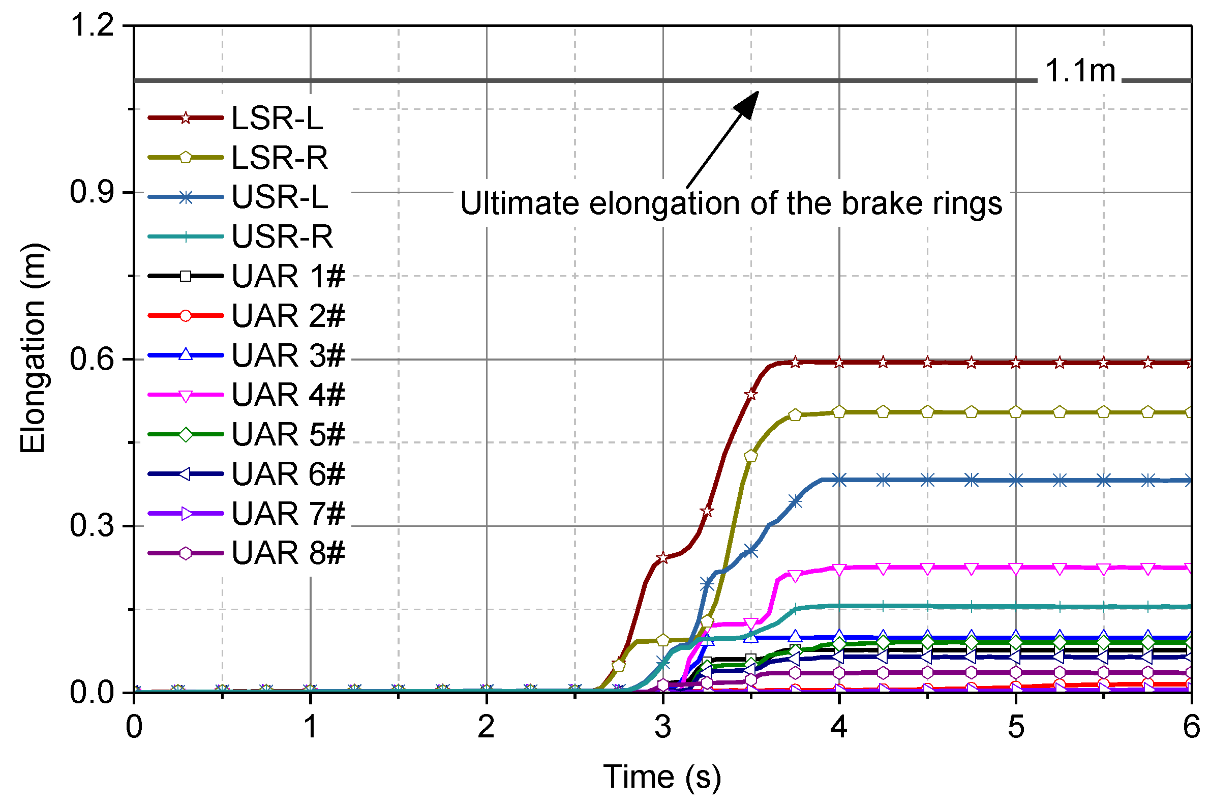
2.4.2. Elongation of Brake Rings

The elongation histories of the brake rings from the numerical simulation are shown in Figure 11. When t = 2.6 s, the brake rings attached to the left and right sides of the lower support rope began to elongate and were stable at 59 cm and 50 cm, respectively, at t = 3.6 s. When t = 2.7 s, the brake rings attached to the left and right sides of the upper support rope began to elongate and were stable at 38 cm and 15 cm, respectively, at t = 3.8 s. The elongations of brake rings attached to the support ropes were unsymmetrical, mainly due to the unsymmetrical impact of the landslide debris on the flexible barrier. In addition to the brake ring attached to the #4 upslope anchor rope, the elongations of other brake rings on the upslope anchor ropes were generally less than 10 cm. The brake ring attached to the #4 upslope anchor rope had the maximum elongation of 25 cm, due to the landslide mass directly impacting post P5, which the #4 upslope anchor rope was connected to.
The deflection of the flexible barrier and the elongation of the brake rings in the field were measured using tape before removing the landslide mass and are summarized with the simulated results in Table 3. It can be seen that the elongations derived from the numerical simulation are comparable to those from the field measurement. The deflection of the flexible barrier was 336 cm and 352 cm in the field and simulation, respectively. The difference was only 4.8%. The larger difference in the elongation of the brake rings attached to the support rope was due to the fact that the numerical model simplified the system to three functional modules, and the propagation effect of the internal force of the support rope was reduced by factors such as friction.
The energy dissipating devices attached to the lower and upper support ropes were two GS-8002 brake rings in parallel, with an ultimate working force of 120 kN. The energy dissipating device attached to the upper slope anchor ropes was a GS-8002 brake ring, with an ultimate working force of 60 kN. The ultimate elongations of the brake rings were all 110 cm. The maximum internal forces of the lower and upper support ropes, as well as the upslope anchor ropes, were all smaller than the ultimate working force of the attached brake rings. This indicates that the brake rings did not all travel to their maximum elongation. In other words, even if the kinetic energy of the landslide of 3200 kJ was three times bigger than the rated energy of the flexible rockfall barrier of 750 kJ, the flexible barrier could intercept the landslide debris successfully, without any damage.

3. Numerical Parametric Study of the Flexible Barrier Subjected to Landslide Debris

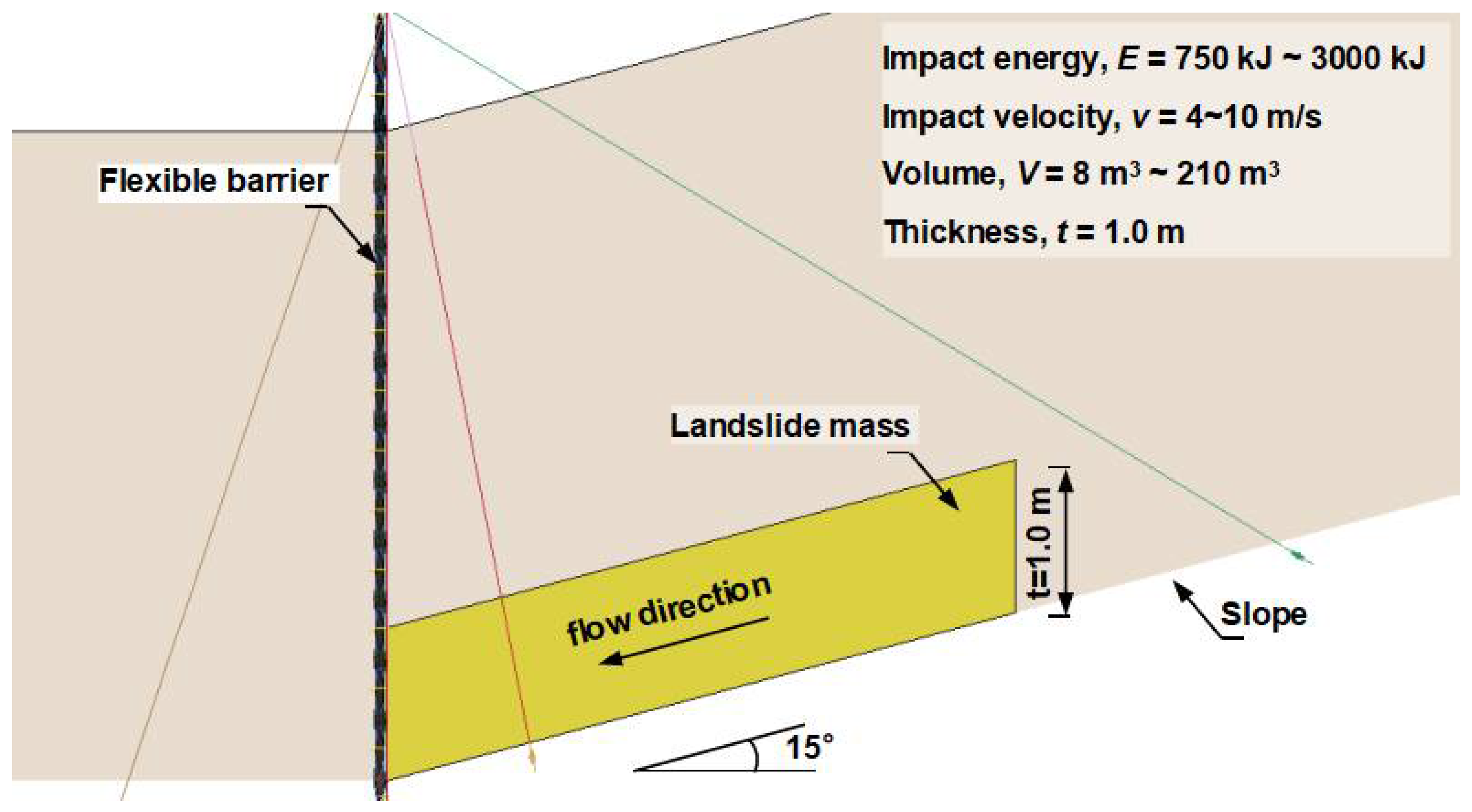
3.1. Model Description

After investigation of the dynamic behavior of the flexible barrier impacted by rockfall and verification of the numerical simulation model, a series of simulations were carried out, to study the performance of the same flexible barrier impacted by landslide debris with different impact energies, ranging from 750 to 3000 kJ. Impact velocities ranging from 4 to 10 m/s were also investigated. A total number of 20 simulation cases are summarized in Table 4. The coupled model of the landslide and the flexible barrier is shown in Figure 12. The angle of the slope was fixed to 15°. The width of the slope was 10 m, which is the post spacing of the flexible barrier. The thickness was also fixed to a common value, in practice of 1.0 m. The density was consistent with the measured value of 1800 kg/m3 in the field investigation. In practice, flexible barriers are commonly installed vertically or sub-vertically on slopes to stop rockfalls or landslides. In the model, the flexible barrier was also set vertically at the end of the slope and in front of the landslide to save computational cost.

3.2. Results of the Parametric Study

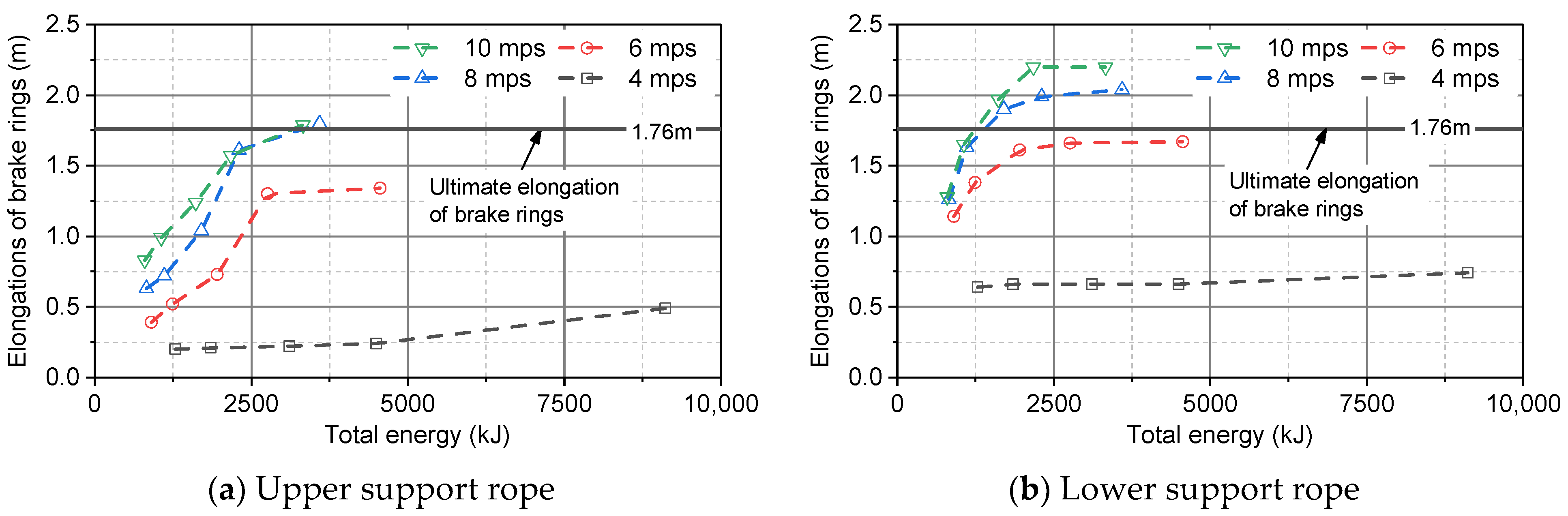
3.2.1. Elongation of the Brake Rings

The energy dissipation ratio denoted as ηs is defined as the ratio of the energy dissipated by the flexible barrier to the impact energy of the landslide mass, as follows:
η s = E s E T
where Es is the energy dissipated by the flexible barrier, and ET is the total energy of the landslide mass, including the initial kinetic energy and the gravitation potential energy.
Figure 13 shows the energy dissipation ratio of the flexible barrier subjected to landslide mass with different total energies and impact velocities. It can be seen that ηs of these cases all are less than 0.4, which means that the flexible barrier was not the main source of energy dissipation. Under the condition of a certain total energy, ηs will increase with the increase of the impact velocity. Under the condition of certain impact velocity, ηs will decrease linearly with the increase of the total energy, as shown in Equations (5)–(7):
η s = k E T + b
k = ( 6.55 v + 5.07 ) × 10 6
b = 0.044 v 0.043
where a, b, and c are factors related to the impact velocity.
In particular, the ηs of the case with a total energy of 796.4 kJ and the impact velocity of 10 m/s was the biggest, and the case with a total energy of 9114.7 kJ and the impact velocity of 4 m/s was the smallest. This can be understood as follows: with the increase of total energy and the decrease of impact velocity, the volume and mass of the debris will increase, so the energy dissipated through the internal and boundary shearing will increase. It should be noted that for the cases with a total velocity of 4 m/s, the above linear decreased relationship of ηs and the total energy is not ideal. When the total energy is less than 4496.0 kJ, the ηs decrease quickly with the increase of total energy. However, the ηs of 9114.7 kJ is almost consistent with that of 4496.0 kJ. This means ηs is stable at 0.03 when the total energy is bigger than 4496.0 kJ, which is in good agreement with Song et al. [46].

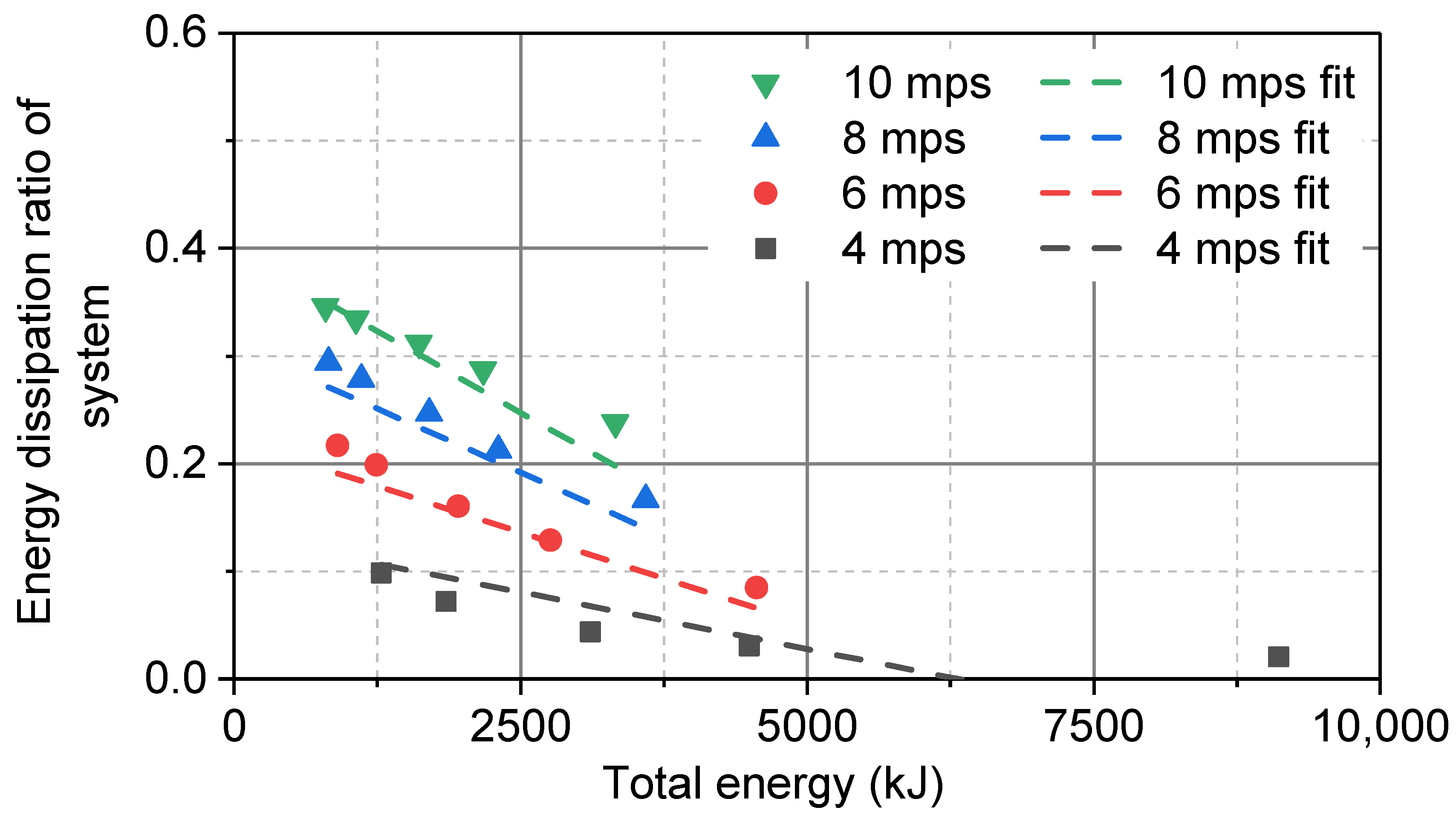
3.2.2. Energy Dissipating Distribution

The energy dissipation ratio denoted as η is defined as follows:
η s = E s E T
where Edis is the energy dissipated by each part, including the brake rings, friction energy, internal energy of landslide, and other components of the flexible barrier, in addition to the brake rings.
Figure 14 shows the distribution of the energy dissipation ratio. It can be seen that the proportion of energy dissipation, ranging from large to small, is the internal energy of landslide, friction energy, brake rings, and other components of the flexible barrier (ring net, steel posts, steel-wire ropes, etc.). The energy dissipated by other components of the flexible barrier in addition to the brake rings was less affected by the impact velocity and impact energy, and was stable at about 5%. The energy dissipated by the brake rings, friction, and internal energy ranged from 1.2% to 26.7%, 25.9 to 46.2%, and 19.2% to 74.2%, respectively. They were all significantly affected by the impact velocity and impact energy. The energy was mainly dissipated by the friction and internal energy.

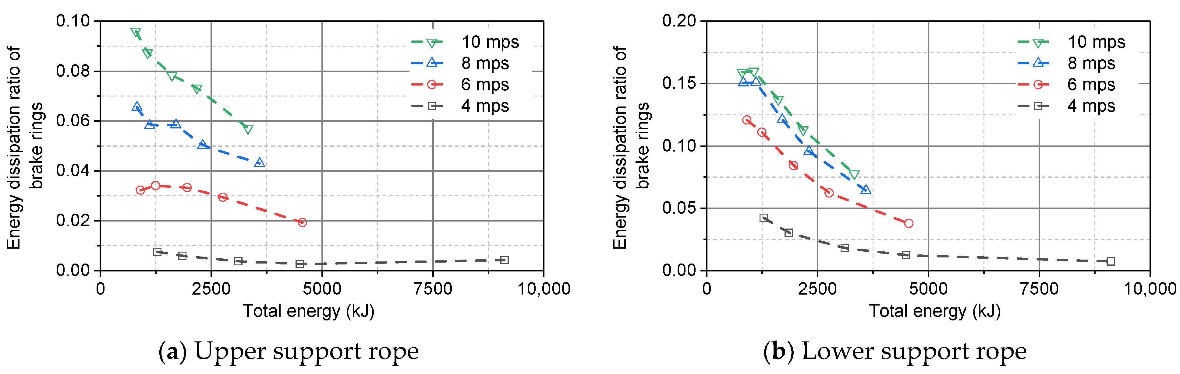
3.2.3. Energy Dissipation Ratio of the Brake Rings

The energy dissipation ratio of the brake rings denoted as ηb was defined, to describe the ratio of the actual energy dissipated by the brake rings to the designed energy dissipation capacity of the brake rings, as follows:
η b = E b E T
where Eb is the actual energy dissipation of the brake rings.
Figure 15a and Figure 16a show the energy dissipation ratio and elongation of the brake rings attached to the upper support rope, respectively. When the impact velocity was 4m/s, the energy dissipation was stable and less than 1%. When the impact velocity was 6~8 m/s, the energy dissipation ratio declined and the elongation increased sharply with the increase of total energy. For case 15, with an impact energy of 3000 kJ and impact velocity of 8m/s, the elongation of the brake rings was the greatest, with a value of 1.80 m. Considering the fact that, in design practice, the elongation should be limited to 80% [41], the flexible barrier of the above cases was identified at its limit state.
Figure 15b and Figure 16b show the energy dissipation ratio and elongation of the brake rings attached to the lower support rope, respectively. For the impact velocity of 6 m/s~10 m/s, with an increase of total energy, the ηb declined quickly and the elongation increased sharply. When the total energy was larger than 2500 kJ, the elongation tended to be stable. When the impact velocity was 4 m/s, the energy dissipation ratio was less than 5%; and with the increase of total energy, the energy dissipation ratio declined and the elongation increased slightly. In particular, for the two cases of 10 m/s with the impact energies of 2000 kJ and 3000 kJ, the elongation of the brake rings was greatest, with a value of 2.2 m.
The energy dissipation ratio of the brake rings attached to the lower support rope was larger than that of the upper support rope, so the maximum intercepted capacity of the flexible barrier subjected to debris was controlled by the lower support rope, which is consistent with that when subjected to boulders [42]. From the energy dissipation ratio of the brake rings attached to the lower support rope, it can be seen that the flexible barrier can withstand a landslide debris impact with an initial impact energy of 3000 kJ, which is four-times the rated energy of a rockfall impact. In addition, with the decrease of impact velocity, the maximum capacity will increase further. Authors should discuss these results and how they can be interpreted from the perspective of previous studies and of the working hypotheses. The findings and their implications should be discussed in the broadest context possible. Future research directions may also be highlighted.

4. Conclusions

Landslide debris was successfully intercepted by a flexible rockfall barrier, without any damage at the Tianwan tunnel entrance of the Chongqing-Huaihua railway in China. Back analysis of the landslide mobility showed that the impact energy was much bigger than the rated energy capacity of the flexible rockfall barrier. To investigate the maximum energy capacity of the flexible rockfall barrier in resisting the landslide debris, parametric analyses of the flexible barrier impacted by landslide debris with different impact energies and velocities were carried out using a coupled modeling technique. The following conclusions can be drawn from this paper:
  • The total energy of landslide debris dissipated by a flexible barrier is less than 40%, most of the energy is dissipated by friction and internal energy.
  • The energy dissipation ratio of a flexible barrier decreases linearly with the increase of the impact energy.
  • The maximum energy capacity of a flexible barrier subjected to landslide debris is controlled by the lower support rope. The maximum energy capacity of a flexible rockfall barrier in resisting landslide debris is four-times that of resisting a rockfall.
In addition, with the decrease of impact velocity, the maximum energy capacity will increase further. Thus, it seems to be conservative to adopt a scaling factor not exceeding 75%, as required in the guidelines in Hong Kong [45], to reduce the energy capacity of a flexible barrier established for a rockfall, in the case of resisting debris flows.
Therefore, this research revealed the relationship of the maximum capability of a flexible barrier in intercepting a rockfall and landslide debris, in terms of energy. The conclusions will hopefully be helpful for engineers to select suitable flexible barriers rated by rockfall impact for landslide debris interception.
However, it should be noted that the findings pertain only to the particular type of flexible barrier, i.e., RXI-075, modeled and the particular impact scenarios in this study. Other impact cases and types of flexible barriers might be worth investigating in further studies. Furthermore, full-scale tests are urgently needed to investigate the behavior of flexible barriers impacted by rockfalls and landslide debris, respectively.

Author Contributions

All authors contributed to the study conception and design. Conceptualization was proposed by L.Z. (Lei Zhao) and Z.Y.; Simulations were performed by L.Z. (Lei Zhao) and L.Z. (Lijun Zhang); Investigation and data collection were performed by L.Z. (Lei Zhao), X.Q., H.X., and Y.Z. The first draft of the manuscript was written by L.Z. (Lei Zhao) and L.Z. (Lijun Zhang); and all authors commented on previous versions of the manuscript. All authors have read and agreed to the published version of the manuscript.

Funding

The work was supported by the National Key Research and Development Program of China (Grant No. 2018YFC1505405), the Department of Science and Technology of Sichuan Province (Grant No. 2020YJ0263), the Fundamental Research Funds for the Central Universities (Grant No. 2682020CX62), and Jiangxi provincial department of transportation research funding (2020H0005).

Institutional Review Board Statement

Not applicable.

Informed Consent Statement

Not applicable.

Data Availability Statement

Not applicable.

Acknowledgments

Thanks to the Research Center for Protection Structures Against Natural Hazards of Southwest Jiaotong University and China Railway 23rd Bureau Group Corporation Limited for providing us with the data, which are important to our research.

Conflicts of Interest

We declare that this manuscript entitled “A case study on the energy capacity of a flexible rockfall barrier in resisting landslide debris” is original, has not been published before, and is not currently being considered for publication elsewhere. We confirm that the manuscript has been read and approved by all named authors and that there are no other persons who satisfied the criteria for authorship but are not listed. We further confirm that the order of authors listed in the manuscript has been approved by all of us. We understand that the Corresponding Author is the sole contact for the Editorial process. He is responsible for communicating with the other authors about the progress, submissions of revisions, and final approval of proofs. Yi-fan Zhang, from Sichuan OST Slope Protection Engineering Co., Ltd., who is responsible for field investigation contribution, does not have any conflict of interest with the other authors.

References

  1. Zhang, Y.; Shen, C.; Zhou, S.; Luo, X. Analysis of the influence of forests on landslides in the Bijie area of Guizhou. Forests 2022, 13, 1136. [Google Scholar] [CrossRef]
  2. Grima, N.; Edwards, D.; Edwards, F.; Petley, D.; Fisher, B. Landslides in the Andes: Forests can provide cost-effective landslide regulation services. Sci. Total Environ. 2020, 745, 141128. [Google Scholar] [CrossRef] [PubMed]
  3. Schmaltz, E.M.; Steger, S.; Glade, T. The influence of forest cover on landslide occurrence explored with spatio-temporal information. Geomorphology 2017, 290, 250–264. [Google Scholar] [CrossRef]
  4. Griffiths, J.W.; Lukens, C.E.; May, R. Increased forest cover and limits on clear-felling could substantially reduce landslide occurrence in Tasman, New Zealand. New Zealand. J. For. Sci. 2020, 50, 1–13. [Google Scholar] [CrossRef]
  5. Huang, R.Q.; Fan, X.M. The landslide story. Nat. Geosci. 2013, 6, 325–326. [Google Scholar] [CrossRef]
  6. Cui, P.; Chen, X.Q.; Zhu, Y.Y.; Su, F.H.; Wei, F.Q.; Han, Y.S.; Liu, H.J.; Zhuang, J.Q. The Wenchuan Earthquake (May 12, 2008), Sichuan Province, China, and resulting geohazards. Nat. Hazards 2011, 56, 19–36. [Google Scholar] [CrossRef]
  7. Grassl, H.; Bartelt, P.A.; Volkwein, A.; Wartmann, S. Experimental and Numerical Modeling of Highly Flexible Rockfall Protection Barriers; Soil and Rock America: Cambridge, MA, USA, 2003. [Google Scholar]
  8. Boetticher, A.V.; Volkwein, A. Numerical modelling of chain-link steel wire nets with discrete elements. Can. Geotech. J. 2018, 56, 398–419. [Google Scholar] [CrossRef]
  9. Available online: https://weibo.com/2615417307/Lwajt7Tto (accessed on 4 June 2022).
  10. Yang, J.; Duan, S.; Li, Q.; Liu, C.Q. A review of flexible protection in rockfall protection. Nat. Hazards 2019, 99, 71–89. [Google Scholar] [CrossRef]
  11. Castro-Fresno, D.; Luis, L.Q.; Bianco-Fernandez, E.; Zamora-Barraza, D. Design and evaluation of two laboratory tests for the nets of a flexible anchored slope stabilization system. Geotech. Test. J. 2009, 32, 315–324. [Google Scholar]
  12. Zhu, Z.H.; Yin, J.H.; Qin, J.Q.; Tan, D.Y. A new discrete element model for simulating a flexible ring net barrier under rockfall impact comparing with large-scale physical model test data. Comput. Geotech. 2019, 116, 103208. [Google Scholar] [CrossRef]
  13. Qin, J.Q.; Yin, J.H.; Zhu, Z.H.; Tan, D.Y. Development and application of new FBG mini tension link transducers for monitoring dynamic response of a flexible barrier under impact loads. Measurement 2020, 153, 107409. [Google Scholar] [CrossRef]
  14. Gentilini, C.; Govoni, L.; Miranda, S.D.; Gottardi, G.; Ubertini, F. Three-dimensional numerical modelling of falling rock protection barriers. Comput. Geotech. 2012, 44, 58–72. [Google Scholar] [CrossRef]
  15. Glover, J.; Denk, M.; Bourrier, F.; Volkwein, A.; Gerber, W. Measuring the kinetic energy dissipation effects of rock fall attenuating systems with video analysis. Proc. Interpraevent Congr. 2012, 1, 151–160. [Google Scholar]
  16. Cui, L.M.; Shi, S.Q.; Wang, M.; Wang, W.K. Research on the impact protection performance of the rockfall attenuator system under multiposition distributed counterweights conditions. Chin. J. Rock Mech. Eng. 2019, 38, 332–342. [Google Scholar]
  17. Duffy, J.D.; DeNatale, J.S. Debris flow mitigation using flexible barriers. In Proceedings of the 47th Annual Highway Geology Symposium, Cody, WY, USA, 6–9 September 1996. [Google Scholar]
  18. Wendeler, C.; Volkwein, A.; Roth, A.; Denk, M.; Wartmann, S. Field measurements used for numerical modelling of flexible debris flow barriers. In Proceedings of the International Conference on Debris-Flow Hazards Mitigation: Mechanics, Prediction, and Assessment, Chengdu, China, 10–13 September 2007. [Google Scholar]
  19. Bugnion, L.; McArdell, B.W.; Bartelt, P.; Wendeler, C. Measurements of hillslope debris flow impact pressure on obstacles. Landslides 2012, 9, 179–187. [Google Scholar] [CrossRef]
  20. Roberto, B.; Andrea, S.; Anna, M.F. Debris flow hazard mitigation: A simplified analytical model for the design of flexible barriers. Comput. Geotech. 2013, 54, 1–15. [Google Scholar]
  21. Tan, D.Y.; Yin, J.H.; Feng, W.Q.; Qin, J.Q.; Zhu, Z.H. Large-scale physical modelling study of a flexible barrier under the impact of granular flows. Nat. Hazards Earth Syst. Sci. 2018, 18, 2625–2640. [Google Scholar] [CrossRef]
  22. Tan, D.Y.; Yin, J.H.; Feng, W.Q.; Zhu, Z.H.; Qin, J.Q.; Chen, W.B. New simple method for calculating impact force on flexible barrier considering partial muddy debris flow passing through. J. Geotech. Geoenviron. 2019, 145, 04019051. [Google Scholar] [CrossRef]
  23. Canelli, L.; Ferrero, A.M.; Migliazza, M.; Segalini, A. Debris flow risk mitigation by the means of rigid and flexible barriers-experimental tests and impact analysis. Nat. Hazards Earth Sys. Sci. 2012, 12, 1693–1699. [Google Scholar] [CrossRef]
  24. Wendeler, C.; Volkwein, A. Laboratory tests for the optimization of mesh size for flexible debris-flow barriers. Nat. Hazards Earth Sys. Sci. 2015, 15, 2597–2604. [Google Scholar] [CrossRef]
  25. Ng, C.W.W.; Song, D.; Choi, C.E.; Koo, R.C.H.; Kwan, J.S.H. A novel flexible barrier for landslide impact in centrifuge. Geotech. Lett. 2016, 6, 221–225. [Google Scholar] [CrossRef]
  26. Song, D. Mechanisms of Debris Flow Impact on Rigid and Flexible Barriers; The Hong Kong University of Science and Technology: Hong Kong, China, 2016. [Google Scholar]
  27. Jiang, R.; Fei, W.P.; Zhou, H.W.; Huo, M.; Zhou, J.W.; Wang, J.M.; Wu, J.J. Experimental and numerical study on the load and deformation mechanism of a flexible net barrier under debris flow impact. B Eng. Geol. Environ. 2020, 79, 2213–2233. [Google Scholar] [CrossRef]
  28. Volkwein, A. Numerical simulation of flexible rockfall protection systems. In Proceedings of the ASCE International Conference on Computing in Civil Engineering, Cancun, Mexico, 12–15 July 2005; pp. 1285–1295. [Google Scholar]
  29. Chan, S.L.; Zhou, Z.H.; Liu, Y.P. Numerical analysis and design of flexible barriers allowing for sliding nodes and large deflection effects. In Proceedings of the One Day Seminar on Natural Terrain Hazard Mitigation Measures, Hong Kong, China, 16 October 2012. [Google Scholar]
  30. Boetticher, A.V.; Volkwein, A.; Wüchner, R.; Bletzinger, K.; Wendeler, C. Numerical modeling of shallow landslide impacts on flexible protection systems and its validation with full scale testing. In Proceedings of the IV International Conference on Computational Methods for Coupled Problems in Science and Engineering, Kos, Greece, 20–22 June 2011. [Google Scholar]
  31. Li, X.; Zhao, J. A unified CFD-DEM approach for modeling of debris flow impacts on flexible barriers. Int. J. Numer. Anal. Methods Geomech. 2018, 42, 1643–1670. [Google Scholar]
  32. Leonardi, A.; Wittel, F.K.; Mendoza, M.; Vetter, R.; Herrmann, H.J. Particle-Fluid-Structure interaction for debris flow impact on flexible barriers. Comput-Aided Civ. Inf. 2016, 31, 323–333. [Google Scholar] [CrossRef]
  33. Cheung, A.K.C.; Yiu, J.; Lam, H.W.K.; Sze, E.H.Y. Advanced numerical analysis of landslide debris mobility and barrier interaction. HKIE Trans. 2018, 25, 76–89. [Google Scholar] [CrossRef]
  34. Kwan, J.S.H.; Chan, S.L.; Cheuk, J.C.Y.; Koo, R.C.H. A case study on an open hillside landslide impacting on a flexible rockfall barrier at Jordan Valley, Hong Kong. Landslides 2014, 11, 1037–1050. [Google Scholar] [CrossRef]
  35. Zhao, L.; He, J.W.; Yu, Z.X.; Liu, Y.P.; Zhou, Z.H.; Chan, S.L. Coupled numerical simulation of a flexible barrier impacted by debris flow with boulders in front. Landslides 2020, 17, 2723–2736. [Google Scholar] [CrossRef]
  36. Albaba, A. Discrete element modeling of the impact of granular debris flows on rigid and flexible structures. Ph.D. Thesis, Université Grenoble Alpes, Grenoble, France, 2015. [Google Scholar]
  37. Ceccato, F.; Redaelli, I.; di Prisco, C.; Simonini, P. Impact forces of granular flows on rigid structures: Comparison between discontinuous (DEM) and continuous (MPM) numerical approaches. Comput. Geotech. 2018, 103, 201–217. [Google Scholar] [CrossRef]
  38. Wendeler, C.; Volkwein, A.; McArdell, B.W.; Bartelt, P. Load model for designing flexible steel barriers for debris flow mitigation. Can. Geotech. J. 2018, 39, 1–18. [Google Scholar] [CrossRef]
  39. Poudyal, S.; Choi, C.E.; Song, D.; Zhou, G.G.D.; Yune, C.Y.; Cui, Y.; Leonardif., A.; Busslingerg, M.; Wendeler, C.; Piton, G.; et al. Review of the mechanisms of debris-flow impact against barriers. In Debris-Flow Hazards Mitigation: Mechanics, Monitoring, Modeling, and Assessment, Proceedings of the 7th International Conference on Debris-Flow Hazards Mitigation, Golden, Colorado, CO, USA, 10–13 June 2019; Association of Environmental and Engineering Geologists: Brunswick, OH, USA, 2019. [Google Scholar]
  40. Gentilini, C.; Gottardi, G.; Govoni, L.; Mentani, A.; Ubertini, F. Design of falling rock protection barriers using numerical models. Eng. Struct. 2013, 50, 96–106. [Google Scholar] [CrossRef]
  41. Koo, R.C.H.; Kwan, J.S.H.; Lam, C.; Ng, C.W.W.; Yiu, J.; Choi, C.E.; Ng, A.K.L.; Ho, K.K.S.; Pun, W.K. Dynamic response of flexible rockfall barriers under different loading geometries. Landslides 2017, 14, 905–916. [Google Scholar] [CrossRef]
  42. Yu, Z.X.; Zhao, L.; Liu, Y.P.; Zhao, S.C.; Xu, H.; Chan, S.L. Studies on flexible rockfall barriers for failure modes, mechanisms and design strategies: A case study of Western China. Landslides 2019, 16, 347–362. [Google Scholar] [CrossRef]
  43. Wartmann, S.; Salzmann, H. Debris flow and floating tree impacts on flexible barriers. In Proceedings of the Conference on Natural Terrain—A Constraint to Development, Hong Kong, China, 14 November 2002; Institution of Mining and Metallurgy: Branch, Hong Kong, 2002. [Google Scholar]
  44. Roth, A.; Kästli, A.; Frenez, T. Debris flow mitigation by means of flexible barriers. In Proceedings of the International Symposium Interpraevent 2004, Trento, Italy, 24–27 May 2004. [Google Scholar]
  45. GEO. Guidelines on Empirical Design of Flexible Barriers for Mitigating Natural Terrain Open Hillslope Landslide Hazards, (Technical Guidance Note No. 37); Geotechnical Engineering Office, HKSAR Government: Hong Kong, China, 2014.
  46. Song, D.; Zhou, G.G.D.; Xu, M.; Choi, C.E.; Li, S.; Zheng, Y. Quantitative analysis of debris-flow flexible barrier capacity from momentum and energy perspectives. Eng. Geol. 2019, 251, 81–92. [Google Scholar] [CrossRef]
  47. EOTA. Falling Rock Protection Kits. EAD 340059-00-0106. European Organization for Technical Approvals, July. 2018. Available online: https://www.nlfnorm.cz/en/ehn/6332 (accessed on 21 July 2022).
  48. Xu, H.; Gentilini, C.; Yu, Z.X.; Qi, X.; Zhao, S.C. An energy allocation based design approach for flexible rockfall protection barriers. Eng. Struct. 2018, 173, 831–852. [Google Scholar] [CrossRef]
  49. Volkwein, A.; Gerber, W.; Klette, J.; Spescha, G. Review of approval of flexible rockfall protection systems according to ETAG 027. Geosciences 2019, 9, 49. [Google Scholar] [CrossRef] [Green Version]
  50. Crosta, G.B.; Imposimato, S.; Roddeman, D.G. Numerical modelling of large landslides stability and runout. Nat. Hazards Earth Sys. Sci. 2010, 3, 523–538. [Google Scholar] [CrossRef] [Green Version]
  51. LS-Dyna Theory Manual; Livermore Software Technology: California, CA, USA, 2006.
Figure 1. Landslide debris occurring near a high-speed railway tunnel exit [9] (Rongjiang, Guizhou, China).
Forests 13 01384 g001
Figure 2. An overall view of the landslide site.
Forests 13 01384 g002
Figure 3. Location of the landslide and the posts of the flexible barrier.
Forests 13 01384 g003
Figure 4. Cross-section along the centerline of the landslide.
Forests 13 01384 g004
Figure 5. An overall view of the landslide site after maintenance.
Forests 13 01384 g005
Figure 6. A front view of the impacted flexible barrier after maintenance.
Forests 13 01384 g006
Figure 7. An isometric view of the back analyzed model.
Forests 13 01384 g007
Figure 8. Typical moments of the interception process.
Forests 13 01384 g008
Figure 9. Moving characteristics of the landslide debris.
Forests 13 01384 g009
Figure 10. Internal forces of ropes of the flexible barrier (Note: UAR 1#~8# means the upslope anchor ropes from left to right).
Forests 13 01384 g010
Figure 11. Elongations of brake rings in the numerical simulation.
Forests 13 01384 g011
Figure 12. Side view of the simulation model for the parametric study.
Forests 13 01384 g012
Figure 13. Energy dissipation ratio of the flexible barrier.
Forests 13 01384 g013
Figure 14. Energy dissipation distribution.
Forests 13 01384 g014
Figure 15. Energy dissipation ratio of brake rings.
Forests 13 01384 g015
Figure 16. Elongation of brake rings.
Forests 13 01384 g016
Table 1. Key parameters adopted to simulate the landslide mass.
Material PropertyAdopted ValueRemarks
Density, ρ1800 kg/m3Roughly measured in the field
Internal friction angle, φ
Shear modulus, G500 kPaBy trial-and-error analysis (Evaluated according to the deformation of the barrier)
Bulk modulus, K1000 kPa
Cohesive strength, c2 kPa
Friction coefficient, μ0.4
Table 2. Configuration and modeling method of the flexible barrier.
ComponentsSpecificationModeling Method
PostHW 150 × 150 × 6 × 10 (Q235)Beam elements with plastic kinematic material
Steel-wire ring netR9/3/300Beam elements with piecewise linear plastic material
Upper support rope1 × 24Discrete cable element
Lower support rope1 × 24
Upslope anchor rope1 × 18
Bypass rope1 × 18
Lateral support rope1 × 18
Lateral anchor rope1 × 18
Energy dissipating device attached to upper/lower support rope2 GS-8002 brake rings in parallelPlastic tension only, translational spring elements
Energy dissipating device attached to upslope anchor rope1 GS-8002 brake ring
Table 3. Deflection of the flexible barrier and elongation of the brake rings.
ComponentsPositionDeflection/Elongations (cm)
FieldSimulation
Flexible barrier-336352
Brake ringsUpper support rope (Left/Right)0/124/16
Lower support rope (Left/Right)43/3859/50
Upslope anchor rope1#78
2#22
3#910
4#2523
5#89
6#76
7#01
8#34
Table 4. Simulation schedule for a parametric study.
Case No.Impact Velocity (m/s)Landslide Volume (m3)Landslide Mass (kg)Impact Energy (kJ)Gravitation Potential Energy (kJ)Total Energy
(kJ)
1452.19.4 × 104750537.11287.1
269.41.3 × 1051000852.61852.6
3104.21.9 × 10515001612.63112.6
4138.92.5 × 10520002496.04496.0
5208.33.8 × 10530006114.79114.7
6623.14.2 × 104750156.1906.1
730.95.6 × 1041000243.81243.8
846.38.3 × 1041500458.31958.3
961.71.1 × 1052000761.82761.8
1092.61.7 × 10530001560.24560.2
11813.02.3 × 10475075.9825.9
1217.43.1 × 1041000110.41110.4
1326.04.7 × 1041500205.61705.6
1434.76.3 × 1042000305.22305.2
1552.19.4 × 1043000593.63593.6
16108.31.5 × 10475046.4796.4
1711.12.0 × 104100065.61065.6
1816.73.0 × 1041500112.11612.1
1922.24.0 × 1042000174.12174.1
2033.36.0 × 1043000330.63330.6
Publisher’s Note: MDPI stays neutral with regard to jurisdictional claims in published maps and institutional affiliations.

