Article

Experimental Analysis of the Performance of Doweled Connections Reinforced with Glass-Fiber-Reinforced Polymer (GFRP) in Wood Pinus spp.

by
Marcos Vinício de Camargo
1,*,
André Luis Christoforo
1,
Laisa Rebeca do Vale Barcarolo
2 and
Jorge Daniel de Melo Moura
2
1
Departament Civil Engineering-PPGCiv, Federal University of São Carlos, Washington Luiz Highway, km 235, São Carlos 13655-905, SP, Brazil
2
Departament Architecture and Urban Design-PPU, State University of Londrina, Celso Garcia Cid Highway, km 380, Londrina 86057-970, PR, Brazil
*
Author to whom correspondence should be addressed.
Forests 2023, 14(5), 931; https://doi.org/10.3390/f14050931
Submission received: 18 March 2023 / Revised: 20 April 2023 / Accepted: 23 April 2023 / Published: 30 April 2023
(This article belongs to the Section Wood Science and Forest Products)

Abstract

:
In line with technological advancements, the construction industry worldwide has sought more efficient building systems in relation to aspects such as increased productivity, reduced material waste and meeting the growing demand. The objective of this research was to use structural joints composed of composite dowels in laminated wood beams as an alternative to connect pieces of wood. Composite materials are composed of a matrix phase and a reinforcement phase and, in civil engineering, are generally applied as reinforcements in concrete structures. This article presents the structural performance of laminated pine timber with composite dowels made of fiber-reinforced polymeric resin (epoxy resin, hardener and glass fiber) (glass-fiber-reinforced polymer, GFRP) with a diameter of 12.5 mm, which was subjected to tensile force in the direction of the connection. For this, an experimental program was carried out that included characterization of the GFRP dowel, characterization of the woods used to make the connection and a tensile test of the connections with the dowels reinforced with fiberglass through a prototype designed specifically for the test. Subsequently, the results were compared with those observed in the literature. In the comparisons, it was possible to conclude that the joints with FRP pins exhibited better performance in terms of shear strength per section than those such as common nails, helical nails (Ardox) and composite structural pins (half-lap, 90°), which were 3.8 mm, 3.4 mm and 6 mm in diameter, respectively. This indicates that this composite material has potential for application in these types of connections. As an original contribution, it proves the feasibility of using this material in dowel joints for wooden structures.

1. Introduction

According to technological advancements, the construction industry worldwide has been looking for more efficient building systems regarding aspects such as increasing productivity, decreasing material waste and meeting increasing demand.
In accordance to [1], wood is a material that has advantages in relation to ease of manufacturing parts, as well as technological developments that have been increasingly explored. Other factors, as suggested by the research of [2,3], are the advantages obtained regarding the consumption of energy and the carbon incorporated in wood and engineered wood when compared with materials such as steel and concrete.
In this context, wood structures are a sustainable solution with great importance in a global context. However, the gradually increasing shortage of wood originally from native forests and its effect on the economy, as well as the strengthening of environmental preservation, have raised the need for the development of sustainable alternatives from cultivated forests [4].
In Brazil, the soil and the climate (light and humidity) are favorable for the growth of forests, such as pine species. However, as a result of their fast growth, the wood originating from these forests exhibits natural flaws. As a result, grading the lumber is crucial before its application in structures [5]. According to [6], visual defects influence the wood’s mechanical properties. Variations found in the modulus of the rupture (MOR) of the compressive strength parallel to the fibers can reach 25.3%, and in terms of stiffness (MOE), the difference was 19.7%.
According to [7], the use of plantation wood in structures in a roof, for instance, may lead to significant savings in terms of materials and cost reductions for the entire structure. However, as this wood has inferior mechanical properties compared with the traditionally used tropical wood species (peroba, cumaru, etc.), adding technology for its utilization is crucial. Consequently, the application of this lumber in structures adds value to this widely available raw material.
Yellow pine wood includes over 100 species. Even though Pinus spp. has been cultivated in Brazil for over a century, initially for ornamental purposes, it has been cultivated for commercial purposes only since the 1960s, mainly for pulp and paper, and secondarily for sawn timber, as well as for resin production. According to [8], the most cultivated species in Brazil are Pinus taeda and Pinus elliottii due to their fast growth and adaptation to the local climate. Brazil’s southern and southeastern regions have the most significant planted area. Regarding the mechanical properties, the research carried out by [9] showed results that suggest a modulus of rupture ranging from 53.14 MPa to 79.97 MPa in cultivated wood aged 9, 13 and 20 years, showing that the material meets the calculated needs of wooden structures.
In wooden structures, the connections are often the weakest points and therefore need special attention. The literature has pointed out [10] that there is a lack of information regarding the behavior of wooden dowel connections in terms of their analytical expressions, as well as numerical models. The mechanical behavior of the binding element and the wood depends on several factors, including the geometric and mechanical properties of the fastener components, the mechanical properties of the wood and the interaction between both elements [11]. The studies by [12,13] presented the types of connections used in wooden structures, including connections through metal pins, subjected to double or single shear stress. However, this type of connection may present disadvantages, such as pathological consequences resulting from the presence of moisture [14].
A structural composite combines the properties of two or more materials and consists of two phases: the matrix and the reinforcement. Fiber-reinforced polymeric composites have high mechanical strength and hardness in relation to the weight of the material. As for the type of fiber, They can be solid or broken fibers, presenting an alignment parallel to the longitudinal axis of the fiber or otherwise [15].
The research carried out by [16,17,18,19] described the techniques used for evaluating defects in composite materials. This allows for better use of the material. Glass fiber has advantages such as wide availability in the market at a low cost and, when associated with a polymeric matrix, it can produce a high-resistance composite.
Among the various types of applications for glass-fiber-reinforced polymers, the research developed by [20] presents studies of the behavior of dowels made with polymeric composites as an alternative for replacing lag-screw connections.
This research article presents the characterization of polymeric composite dowels reinforced with fiberglass (GFRP, glass-fiber-reinforced polymer) wood connections submitted to double-cut loading. This article presents the results from the development of a test program, in which the joints were exposed to traction in a line and in the direction of the tension force, and it was possible to analyze the resistance of the last connection, as well as the modulus of rupture, when compared with the results found in similar research. The samples were loaded under tension, and the ultimate strength and the stiffness were recorded, and then the results were compared with the literature.

2. Materials and Methods

The test program was carried out at the Structures Laboratory of the Londrina State University (UEL), and it included the stages describing the structural composite dowelled joints as well as those developed in the research of [20]. These stages were obtained from a performance test of direct tension; later, the performance of tension in a line and in the direction in which the force was applied was also tested.

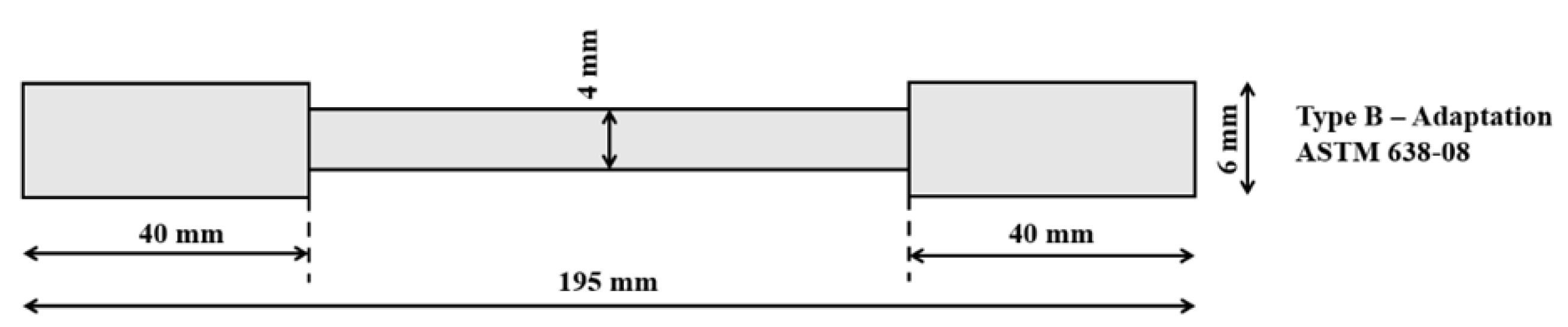
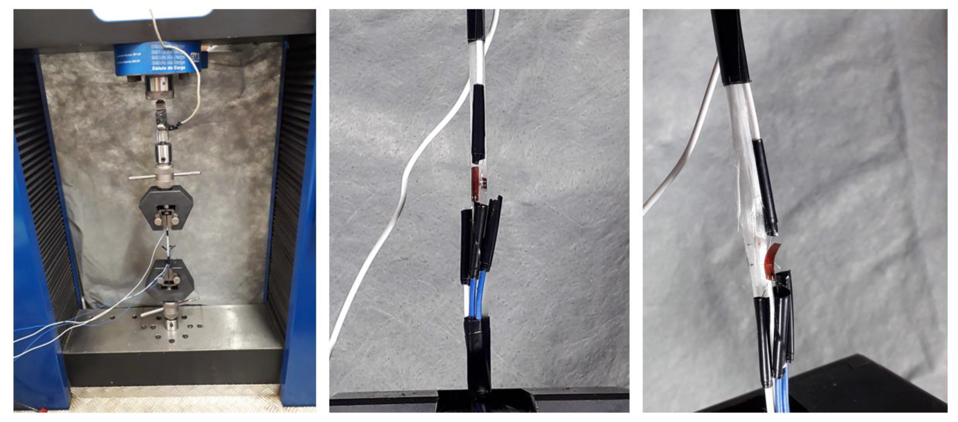
2.1. Characterization of the GFRP Dowels

The manufacture of the dowel specimens and the loading test were guided by the provisions of the ASTM [21]. The standard allows the measurement of the geometrical features of the dowel in order to perform the test. The dowel’s cross-section area showed varying diameters in the central section and edges. Figure 1 shows the specimen’s dimensions.
The dowels consisted of a polymeric matrix made of low-viscosity, mature, room-temperature epoxy resin (Araldite® Ly 1564BR epoxy) and a hardener (Aradur® 2963). The reinforcement was Advantex E-CR GLASS fiberglass, provided by Owens Corning. In total, 11 dowels were prepared through the pultrusion process, submitted to curing at room temperature and taken out of the mold after 24 h. Figure 2 shows the specimens.
The number of specimens was according to [21]. For each specimen, the longitudinal and transversal deformation parameters, the ultimate tensile strength and the modulus of elasticity were measured, and Poisson’s ratio was calculated.
The proportion by volume used in the mix for the manufacture of the dowels was 37% resin and 63% reinforced glass fiber, as indicated by the fiberglass manufacturer Advantex E-CR GLASS (2011) in the technical manual. For a dowel with the dimensions of 195 mm in length, 6 mm in diameter at the ends and 4 mm in diameter at the center, the total volume (3.705 cm3) was filled with 1.65 g of Araldite Ly 1564BR, 0.72 g of Aradur 2963 and 4.04 g of fiberglass. The dowel’s total weight was recorded, and the dimensions were measured. Eleven specimens were produced (Specimens 1 to 11), and six of them were selected through visual grading for the tension test (Specimens 5 to 10). The test followed the provisions of [21]. A tension force with a controlled loading rate was applied in order to simultaneously measure the tangential and longitudinal deformations with the help of strain gages (brand KFG-5-120-C1-11, Kyowa, Osaka, Japan). Each specimen was lightly sanded so that the strain gauges adhered more easily. Markings were made to centralize the gauges in the specimens. Before being glued, the strain gages were tested with a Minipa multimeter ET3021 to detect possible defects, which did not occur. The precision adhesive used for bonding the strain gages was Super Bonder (Loctite brand). This adhesive is based on cyanoacrylate, and its main characteristic is its anaerobic curing in the absence of air. It hardens within a brief time from 10 to 30 s, and must be applied with uniform pressure over the whole area of the strain gage. After bonding, the strain gages were tested again with a multimeter, which confirmed the resistance of 120 ohms, according to the technical data sheet on the package.
The test was performed with a hydraulic universal press with a 30,000 kN load capacity (brand EMIC DL 30000) equipped with a pair of wedge grips, as presented in Figure 3. The data acquisition system used was Lynx AqDados 7.2.

2.2. Wood Characterization

To test the specimen, a grading protocol of the wood pieces was performed. As indicated by the literature [13] at least six specimens were prepared for each connection type. Twenty Pinus spp. wood boards with dimensions measuring 20 mm thick, 300 mm wide and 3000 mm long, and showing a 12% average moisture content (MC) were purchased in the market of Londrina, PR, Brazil.
After measurement of the dimensions and weighing, the wood pieces were visually graded according to [13]. Afterwards, they were submitted to mechanical grading to determine the effective modulus of elasticity (MOE) as indicated by the same standard. The four-point bending test procedure consisted of applying a 500 N load to the thirds of the boards (20 mm in thickness, 140 mm in width and 3000 mm in length), according to Figure 4.
The values of MOE were submitted to a statistical analysis with a confidence interval of 95%, with the aim of including the whole group of specimens with a similar average MOE and standard deviation.
The setup was designed so that the board with the lowest modulus of elasticity was part of the same specimen as the board with the highest modulus of elasticity, and so on. For the manufacture of the specimens, the method of [22] was adapted, in which the average dimensions of the specimens were 60 mm thick, 140 mm wide and 1500 mm long. Each specimen was composed of five pieces of 20 mm in thickness, 140 mm in width and various lengths, with the external layers of one piece being 650 mm and another being 850 mm long, and a continuous middle (internal) layer 1500 mm long, configured across a 330 mm region of the splice. In this cutting process, the regions containing defects and knots were discarded, according to Figure 5.

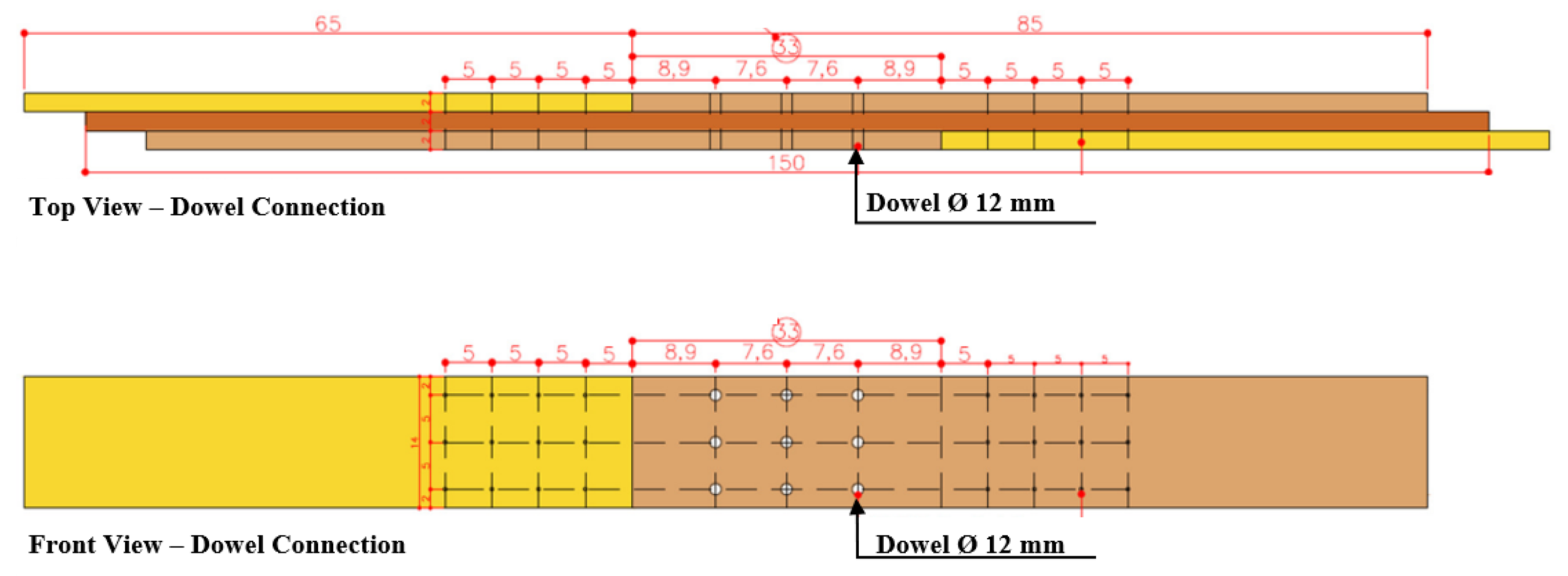
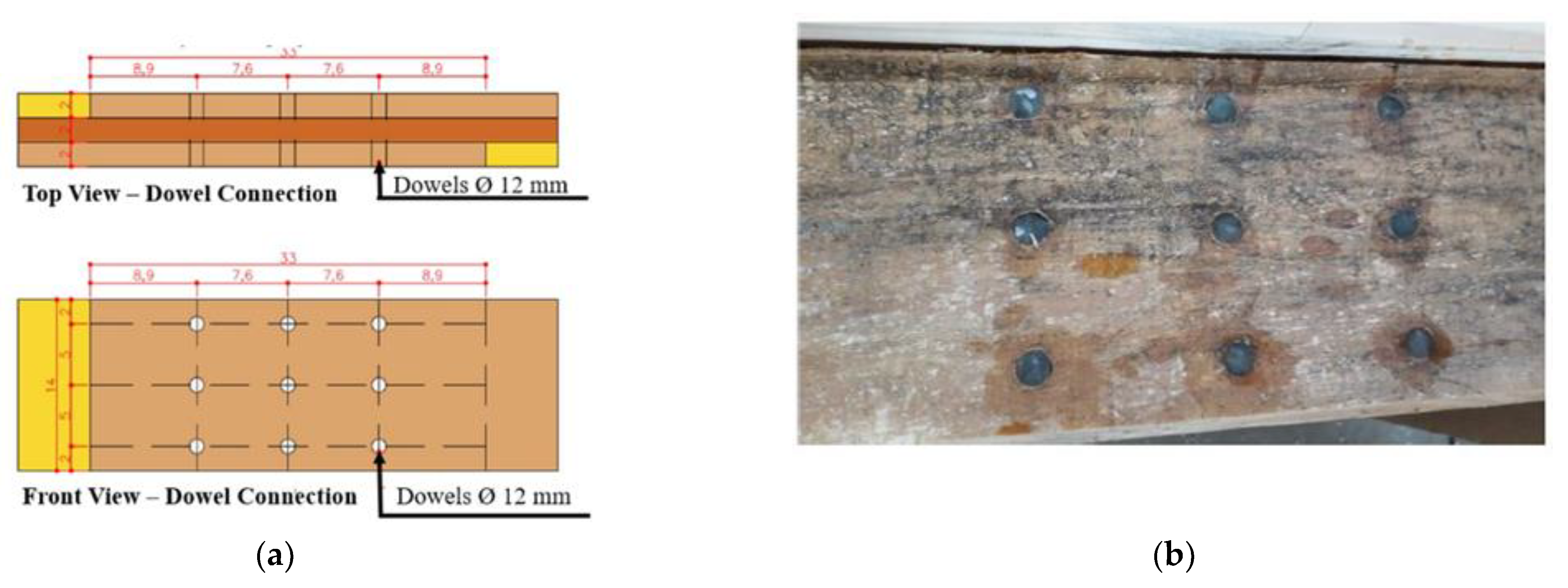
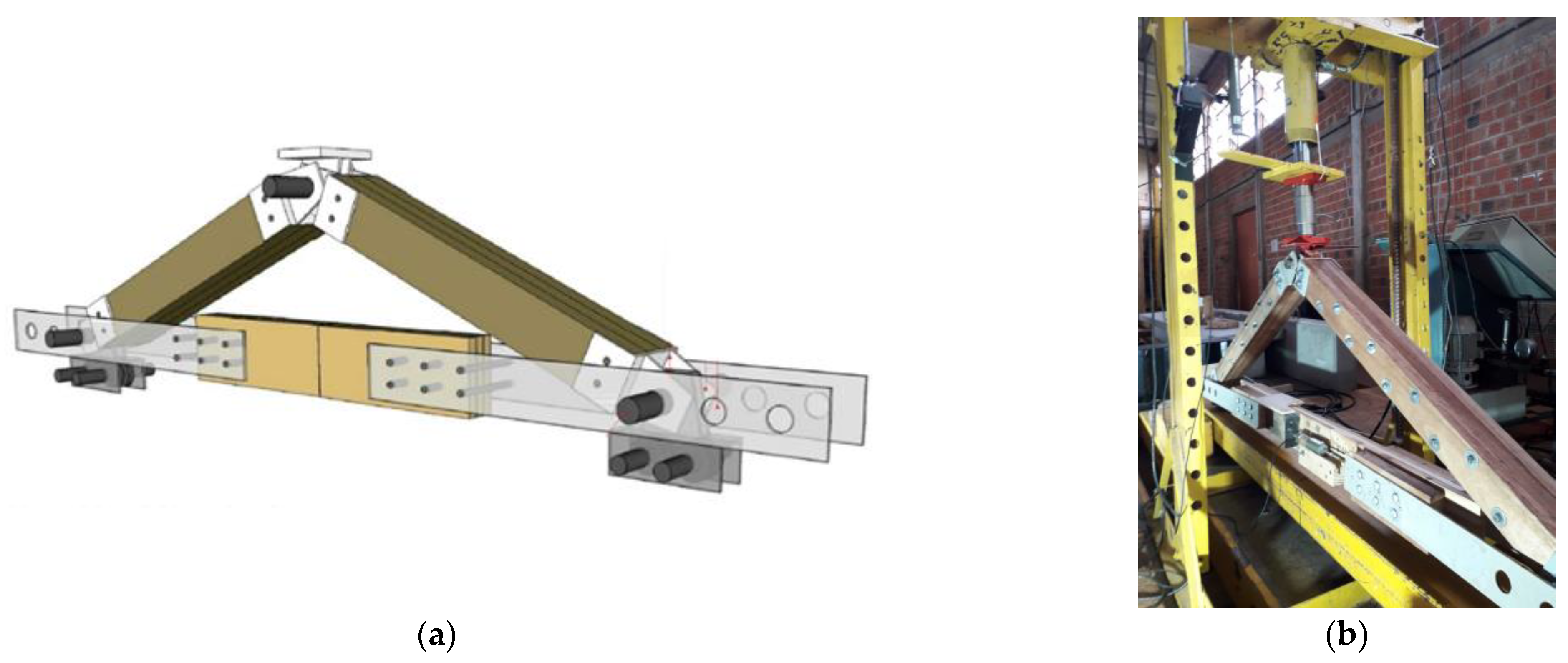
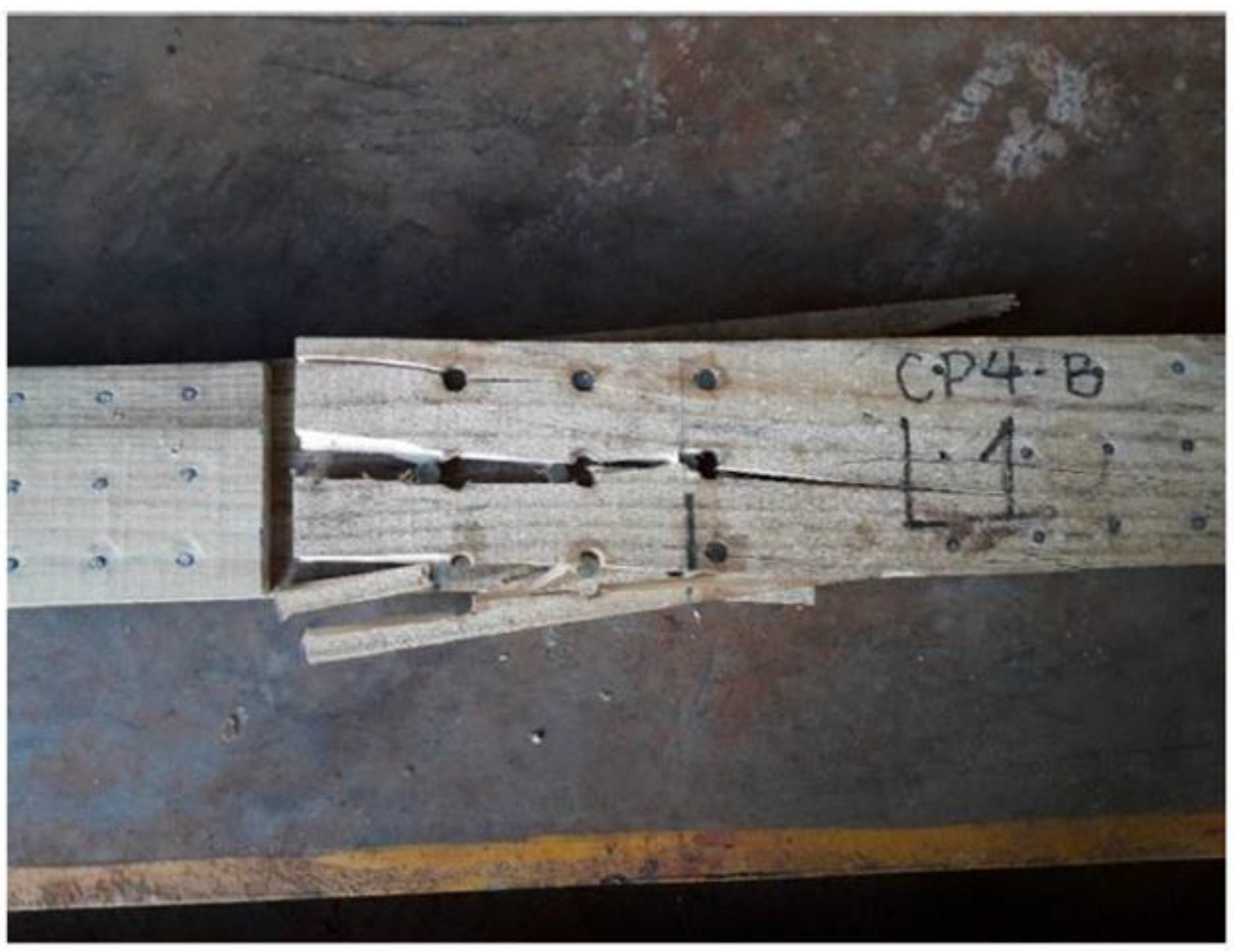
2.3. Tested Connection Specimen

The connection used to perform the test was based on the research of [22]. Nine dowels were inserted into pre-drilled holes, with no fastening material between the dowels and the timber pieces. The process of analysis consisted of checking the transmission of effort in the splicing area as well as the rupture mechanism, submitting the connection to shear stress with a double shear section. The dowels’ positioning and the minimum space between the connective elements were according to the directions of [13], with the splice length set to 330 mm. Figure 6 shows the elements’ dimensions and the dowels’ positions. In the figure, it is possible to see that the splicing length of 330 mm consisted of three layers: a continuous inner layer and discontinuous outer layers. Nine GFRP 12 mm diameter dowels were inserted in the splicing area as shown in Figure 6.
To perform the tension test, an apparatus simulating the connection’s performance when submitted to tension was conceived, as shown in Figure 7.

2.4. Calculation of the Connection’s Stiffness

After determining the theoretical resistance of each connection, the instantaneous slip module found (kser) (kN/mm) for the connection was displayed according to [23] through a linear regression analysis. Equations (1) and (2) present the formulae for calculating the characteristics of resistance and slip. Equations (1) and (2) present the formulae for calculating the characteristics of the strength and slip displacement.
K ser = 0.4   F est / υ i , m o d
where Fest is the maximum estimated load, υ i , m o d is the initial slip.
υ i , m o d = 4 / 3 ( υ 0,4 υ 0,1 )
where υ 0,4 is the slip at 0.4 Fest and υ 0,1 is the slip at 0.1 Fest.

3. Results

Figure 8 shows the load versus the longitudinal and transversal deformation observed during the test.
Figure 8a,b above shows the linear behavior with constantly declining lines for both longitudinal and transversal deformation with the stress values σ = 140 MPa and τ = 140 MPa. From the test results, it was possible to determine the features of the dowels made according to a composite formulation (resin + fibers), which showed isotropic behavior. Table 1 shows the features of a structural composite dowel.
The NDT (non-destructive tests) indicated that the boards from which the connection components were sawn were of Class C20, and it should be noted that the greater the strength grade of the wood, the greater the probability of a rupture occurring in the dowels (ultimate strength, 20 MPa; MOE, 5.000 MPa). Table 2 shows the homogeneity pairs and their corresponding modulus of elasticity—MOE—observed to the connection components.
Figure 9 shows the curve of a typical connection’s behavior under tension. The resistance of the connection was obtained by tracing a parallel straight line 0.2% away from the secant line, according to [13].
Table 3 shows the complete test results. Only SP11 presented a low resistance value. All the other recorded values ranged from 28.80 to 75.40 kN, indicating the excellent representation of the tests. Table 3 also presents the instantaneous slip modulus found (kser) (kN/mm) for the connection according to [23] through linear regression analysis.
When analyzing the results, we noted that SP 11 showed a low value (28.8 kN); the reason for this result can be explained by the resistance of the board used for making the connection, where parts were cut close to the tree’s pith. During the evaluation of the mode of failure, according to Figure 10, it was observed that all of them broke in the timber, not due to the shear of the dowels, thus increasing the coefficient of variation of the results. According to Table 3, the average value of the maximum displacement was 2.07 mm. In an analysis of the average values of the resistances, not considering the performance of SP 11, the values of the other specimen showed quite high results.
The analysis of the instantaneous slip modulus (kser) demonstrated the variability of the results as well as the linear regression obtained in the test.
It was interesting to observe that the calculated values, in general, underestimated those obtained in the tests regarding stiffness (linear regression); therefore, the parameters of the standard [23] can be considered to be quite conservative.
The observed failure indicated evidence of the great stiffness of the connection, which caused the failure of the wood. Figure 10 shows the mode of rupture.
In all the specimens, the rupture occurred in the wood around the splice region. Ruptures due to the longitudinal shear of the wood at the cutting line of the dowels happened in four specimens (SP4, SP11, SP12 and SP14). In two others (SP7 and SP10), the failure occurred in the transversal direction. Table 4 presents the individual resistance capacity of the dowels per cross-section according to the literature [24]. Compared with the published data, it is possible to observe that the dowel connections developed in this research showed higher performance than the smooth shank nail, half-laps and coiled shank (Ardox) nail connections. In their work, the authors of [22] reported that the nails were nailed perpendicularly to the components’ surface and were manufactured with the same specimen type and the same splice connection arrangement (nine nails distributed in three rows and three columns) as [24], and were subjected to shear stress in a tensile test of the splices. Others [25] studied different angles of nailing subjected to shear stress, as in the research of [24]. The authors of [26] analyzed two types of composite dowel connections (half-lap, 90°; edge, 45°) in CLT panels, assembled with the same adhesive as used by [20] (Araldite® Ly 1564BR epoxy adhesive, Aradur® 2963 hardener and Advantex E-CR GLASS fiberglass) in CLT panels subjected to shear stress.
In Table 4, it is possible to see that the resistance of the connection studied here showed 66% higher resistance per connector pin than that obtained by the same connection made with Ardox coil shanked nails.

4. Conclusions

Based on the experimental program carried out, it is possible to draw conclusions regarding the characterization of the dowels as well as the resistance of the connection with GFRP dowels.
Pultrusion was a suitable dowel production process, as it allowed complete soaking of the fibers, and the visual aspects of the dowel proved to be related to its performance.
The characterization tests of the dowels allowed the calculation of the tension and deformation parameters.
The stiffness value obtained in the test (linear regression) was 11% higher than that calculated according to literature reports.
The theoretical values of resistance calculated according to standard provisions, in general, underestimated those observed in the tests and suggest the need for more studies on dowel connections made from structural composite GFRP. Dowels made of a polymer reinforced with fiberglass can be a good alternative to wooden connections, but it is important to carry out further research on various dimensions, classes of timber strength and the positioning of the dowels in the connection.
When we compared the results with similar research in the literature, the dowel connections showed better performance in terms of resistance per cutting section, as it was 3.13 kN higher than those found for smooth shanked nails 3.8 mm in diameter (0.88 kN), Ardox nails 3.4 mm in diameter (1.88 kN) and prefabricated structural composite dowel connections 6 mm in diameter (1.65 kN).
Regarding the mode of rupture, no dowels failed; in all specimens, ruptures occurred due to longitudinal or transverse shear in the timber pieces in the line of the dowels.

Author Contributions

Conceptualization, L.R.d.V.B. and J.D.d.M.M., Methodology: L.R.d.V.B. and M.V.d.C.; Validation: J.D.d.M.M. and A.L.C.; Resources: L.R.d.V.B. and M.V.d.C.; Data curation: M.V.d.C. and J.D.d.M.M.; Writing—original draft preparation: M.V.d.C.; Writing—review and editing: J.D.d.M.M. and A.L.C.; Supervision: J.D.d.M.M. All authors have read and agreed to the published version of the manuscript.

Funding

This research received no external funding.

Data Availability Statement

The data presented in this study are available on request from the corresponding author.

Conflicts of Interest

The authors declare no conflict of interest.

References

  1. O’Ceallaigh, C.; Conway, M.; Mehra, S.; Harte, A.M. Numerical Investigation of Reinforcement of Timber Elements in Compression Perpendicular to the Grain Using Densified Wood Dowels. Constr. Build. Mater. 2021, 288, 122990. [Google Scholar] [CrossRef]
  2. Balasbaneh, A.T.; Sher, W. Comparative Sustainability Evaluation of Two Engineered Wood-Based Construction Materials: Life Cycle Analysis of CLT versus GLT. Build. Environ. 2021, 204, 108112. [Google Scholar] [CrossRef]
  3. Goldhahn, C.; Cabane, E.; Chanana, M. Sustainability in Wood Materials Science: An Opinion about Current Material Development Techniques and the End of Lifetime Perspectives. Philos. Trans. R. Soc. A Math. Phys. Eng. Sci. 2021, 379, 20200339. [Google Scholar] [CrossRef] [PubMed]
  4. Biazzon, J.C.; Lima, M.P.; Munis, R.A.; De Araujo, V.A.; Morales, E.A.M.; Gonçalves, M.T.T.; Bueno, M.A.P.; Moizes, F.A.; Leite, S.S.; Salvadeo, V.M.; et al. Shear Strength of Eucalyptus Saligna Wood Joints Bonded with Polyvinyl Acetate Adhesive. BioResources 2019, 14, 4590–4602. [Google Scholar] [CrossRef]
  5. Vilela, R.; Mascia, N.T. Avaliação de Propriedades Mecânicas Da Madeira de Pinus Taeda Provenientes de Placas de Cross Laminated Timber. Ambient. Construído 2021, 21, 89–110. [Google Scholar] [CrossRef]
  6. Ballarin, A.S.; Rodrigues, S.A.; Ballarin, A.W.; Júnior, C.C. Classificação Visual e Mecânica Simplificada Da Madeira de Pinus Spp—Avaliação Com Estatística Multivariada. In Proceedings of the XVI Encontro Brasileiro em Madeiras e em Estruturas de Madeira e III Congresso Latino-Americano de Estruturas de Madeira, São Carlos, Brazil, 26–28 March 2018; pp. 1–12. [Google Scholar]
  7. Lahr, F.A.R.; Christoforo, A.L.; Fiorelli, J. Influence of Nails Size and Layout to Obtain the Reduction Coefficient of Moment of Inertia for Timber Beams with Composite Cross Section. Eng. Agric. 2016, 36, 715–723. [Google Scholar] [CrossRef]
  8. Bolgenhagen, A. Avaliação Comparada Dos Parâmetros Que Influenciam Na Colagem Lateral De Painéis De Madeira De Pinus Elliottii E Pinus Taeda. Rev. Eletrônica Alto Val. Itajaí 2018, 10, 31–48. [Google Scholar] [CrossRef]
  9. de Oliveira, F.L.; de Lima, I.L.; Garcia, J.N.; Florsheim, S.M.B. Propriedades Da Madeira de Pinus Taeda Em Função Da Idade e Da Posição Radial Da Tora. Rev. Inst. Flor. 2006, 18, 59–70. [Google Scholar]
  10. Teodorescu, I.; Pereira, B.; Aquino, C.D.; Branco, J.M. Experimental Evaluation of Dowel-Type Timber Joints with Wooden Dowels. Proc. Inst. Civ. Eng. Struct. Build. 2020, 173, 927–938. [Google Scholar] [CrossRef]
  11. Izzi, M.; Rinaldin, G.; Polastri, A.; Fragiacomo, M. A Hysteresis Model for Timber Joints with Dowel-Type Fasteners. Eng. Struct. 2018, 157, 170–178. [Google Scholar] [CrossRef]
  12. EN 1995-1-1:2004+A1; Design of Timber Structures—Part 1-1: General Common Rules for Buildings Eurocode 5. CEN: Brussels, Belgium, 2004; Volume 1.
  13. Associação Brasileira de Normas Técnicas. NBR 7190-1: Projetos de Estruturas Em Madeira; ABNT: Rio de Janeiro, Brazil, 2022; ISBN 9788507091424. [Google Scholar]
  14. Ceraldi, C.; D’Ambra, C.; Lippiello, M.; Prota, A. Restoring of Timber Structures: Connections with Timber Pegs. Eur. J. Wood Wood Prod. 2017, 75, 957–971. [Google Scholar] [CrossRef]
  15. William, D.; Callister, J. Ciência e Engenharia de Materiais: Uma Introdução; Cengage Learning: Rio de Janeiro, Brasil, 2000. [Google Scholar]
  16. Yahng, J.S.; Yee, D.S. High-Speed Time-and Frequency-Domain Terahertz Tomography of Glass-Fiber-Reinforced Polymer Laminates with Internal Defects. Appl. Sci. 2021, 11, 4933. [Google Scholar] [CrossRef]
  17. Liu, J.L.; Mencattelli, L.; Zhi, J.; Chua, P.Y.; Tay, T.E.; Tan, V.B.C. Lightweight, Fiber-Damage-Resistant, and Healable Bio-Inspired Glass-Fiber Reinforced Polymer Laminate. Polymers 2022, 14, 475. [Google Scholar] [CrossRef] [PubMed]
  18. Han, Z.; Jeong, S.; Jang, J.W.; Woo, J.H.; Oh, D. Ultrasonic Attenuation Characteristics of Glass-Fiber-Reinforced Polymer Hull Structure. Appl. Sci. 2021, 11, 6614. [Google Scholar] [CrossRef]
  19. Han, Z.; Jang, J.; Lee, S.G.; Lee, D.; Oh, D. Error Analysis of Non-Destructive Ultrasonic Testing of Glass Fiber-Reinforced Polymer Hull Plates. J. Compos. Sci. 2021, 5, 238. [Google Scholar] [CrossRef]
  20. de Almeida, A.C.; de Melo Moura, J.D. Mechanical Behavior of GFRP Dowel Connections to Cross Laminated Timber-CLT Panels. Forests 2022, 13, 320. [Google Scholar] [CrossRef]
  21. ASTM D638-14; Standard Practice for Preparation of Metallographic Specimens. ASTM International: West Conshohocken, PA, USA, 2016; Volume 82, pp. 1–15.
  22. Recco, E.G. Análise Experimental Do Sistema de Cobertura Caibro Treliçado Em MLP (Madeira Laminada Pregada) Utilizando Madeira Serrada de Pinus Spp; Universidade Estadual de Londrina: Londrina, Brazil, 2015. [Google Scholar]
  23. EN 26891:1991; Timber Structures. Joints Made with Mechanical Fasteners. General Principles for The Determination of Strength and Deformation Characteristics (ISO 6891:1983). CEN: Brussels, Belgium, 1991.
  24. do Vale Barcarolo, L.R. Estudo de Eficiência de Ligações Por Cavilha de Compósito Estrutural Em Vigas de Madeira Laminada, Dissertação (Mestrado em Arquitetura e Urbanismo). Ph.D. Thesis, Centro de Tecnologia e Urbanismo, Universidade Estadual de Londrina, Londrina, Brazil, 2019. [Google Scholar]
  25. Branco, J.M.G. Comportamento Das Ligações Tipo Cavilha Em Estruturas Mistas Madeira-Betão. Master’s Thesis, Universidade do Minho, Braga, Portugal, 2003; p. 150. [Google Scholar]
  26. Almeida, A.C. de Aplicação de Compósitos Poliméricos Reforçados Com Fibras de Vidro—GFRP Em Ligações Cavilhadas Para CLT. Master’s Thesis, Universidade Estadual de Londrina, Londrina, Brazil, 2019. [Google Scholar]
Figure 1. Geometry of the polymeric composite dowel specimens.
Forests 14 00931 g001
Figure 2. The polymeric composite dowel specimens.
Forests 14 00931 g002
Figure 3. Tension test of the polymeric composite dowel specimens.
Forests 14 00931 g003
Figure 4. Non-destructive static test.
Forests 14 00931 g004
Figure 5. Specimen of the dowel connection.
Forests 14 00931 g005
Figure 6. Diagram of the connection: (a) dimensions of the connection; (b) actual connection.
Forests 14 00931 g006
Figure 7. Testing apparatus. (a) Schematic of the apparatus scheme; (b) performing the test.
Forests 14 00931 g007
Figure 8. Stress curve versus deformation. (a) Longitudinal deformation; (b) transverse deformation.
Forests 14 00931 g008
Figure 9. Load (force) versus deformation (slip).
Forests 14 00931 g009
Figure 10. Failure of a connection.
Forests 14 00931 g010
Table 1. Behavior of the structural composite dowel.
PropertiesStructural Features of the Dowel
Ultimate normal strength (σ)320 MPa
Longitudinal deformation (ε1)0.00228
Cross-sectional deformation (ε2)0.00044
Poisson ratio (ν)0.195
Longitudinal modulus of elasticity (E)61,403.5 MPa
Transverse modulus of elasticity (G)25,691.8 MPa
Shear stress ( τ )14.4 MPa
Table 2. Modulus of elasticity (MOE) of the specimens (Pinus spp.).
Modulus of Elasticity of the Connection Pieces
IC 95%; Ec0 = 5492.19 MPa–Ec0 = 6695.15 MPa
Piece Reference Ec0 (MPa)Piece ReferenceEc0 (MPa)Average
Ec0 (MPa)
L084040.44L178878.156359.29
L024418.14L238557.196487.66
L144473.72L068208.256340.99
L014692.05L188050.006371.03
L044787.96L247705.646246.80
L104801.14L197446.186123.66
L074858.28L117086.685972.48
L135005.07L126743.055874.06
L095195.28L156415.385805.33
L215349.68L226342.585846.13
L055438.28L166182.165810.22
Table 3. Resistance and displacement.
SpecimenUltimate Load of the Connection (kN)Displacement
(mm)
EN 26891 (1991) Kser (kN/mm)Linear Regression Kser (kN/mm)
SP473.702.2338.5041.67
SP774.501.4835.9358.91
SP1051.003.0329.5916.62
SP1128.801.3032.5825.99
SP1234.802.6813.1914.34
SP1475.401.6727.7038.54
Average56.372.0729.5832.68
Standard deviation (STD)21.190.7016.0616.98
Coefficient of variation (COV)37.60%33.69%47.05%51.97%
Table 4. Comparison of the results.
DesignationBranco (2003)
Smooth Common Nail (90°)
Almeida (2019)
Half-Lap Composite Dowel
Barcarolo (2019)
Composite Dowel
Recco (2015) Coiled Shank (Ardox) Nail
Doweled connection, F (kN)3.5113.1856.3733.84
Displacement max. (mm)14.0314.732.07--
Number of connectors2499
Diameter of connectors (mm)3.86123.4
Length of connectors (mm)1001006072
Resistance per connector (kN)0.881.653.131.88
Disclaimer/Publisher’s Note: The statements, opinions and data contained in all publications are solely those of the individual author(s) and contributor(s) and not of MDPI and/or the editor(s). MDPI and/or the editor(s) disclaim responsibility for any injury to people or property resulting from any ideas, methods, instructions or products referred to in the content.

