Article

Research on the Performance and Control Strategy of Electro-Hydraulic Servo System for Selective Hole Digging Tree Planter

1
School of Mechanical and Electrical Engineering, Northeast Forestry University, Harbin 150040, China
2
Research Institute of Wood Industry, Chinese Academy of Forestry, Beijing 100091, China
3
School of Intelligent Manufacturing Engineering, Harbin Huade University, Harbin 150025, China
4
Supervision and Inspection Center, Harbin 150006, China
*
Authors to whom correspondence should be addressed.
Forests 2024, 15(10), 1744; https://doi.org/10.3390/f15101744
Submission received: 30 August 2024 / Revised: 24 September 2024 / Accepted: 27 September 2024 / Published: 2 October 2024
(This article belongs to the Special Issue New Development of Smart Forestry: Machine and Automation)

Abstract

:
Compared to agricultural environments, afforestation sites are more complex, often presenting issues such as undulating and uneven terrain. These conditions lead to instability in hole digging depth and plant spacing during continuous movement, and the hole shape may not meet expectations. Additionally, the hydraulic system exhibits slow response speed and long steady-state time, affecting the quality of sapling planting. To address these issues, this paper designs an intelligent planting control system for intermittent hole digging under continuous dynamic movement, based on a large tree planter. The focus is on studying the dynamic accuracy of the hole digging cylinder to resolve the instability of plant spacing and planting depth in actual planting processes. Firstly, a motion trajectory model of the intermittent hole digging mechanism is established to obtain the relationship between the displacement trajectory of the rotating cutter and the displacements of the floating cylinder and the hole digging cylinder. Secondly, a mathematical model of the electro-hydraulic servo system is established to control the dynamic accuracy of the hole digging operation. Finally, a Simulink simulation model of the system is established to analyze the performance indicators of the hydraulic system during operation using step and sinusoidal excitation signals. The test results show that the displacement of the hydraulic piston rod can ensure a linear extension trend within the range of 0 to 0.4 m, and the extension distance of the hole digging cylinder in the planting system is 0 to 0.35 m, ensuring linear change within this stroke. When the system’s extension command is 1 V, the actual output is 0.6 m, with a relative error of less than 10% compared to the simulation value, indicating that the control strategy can effectively improve the dynamic performance of the system. When the hydraulic system is in a steady-state extension state at 50 to 58.6 s, the relative error with the simulation value is 7.3%, meeting the “double ten indicators” requirement. The research results clearly verify the superior performance of the proposed intelligent control system, and the proposed control strategy has great potential in practical applications, promising to improve afforestation quality by stabilizing planting spacing and planting depth.

1. Introduction

With the increasing awareness of global ecological environment protection, afforestation has received widespread attention as an important means to improve the ecological environment and promote biodiversity [1,2]. In modern forestry production, improving the efficiency and quality of tree planting has become an urgent problem to be solved. Traditional tree planting machines are simple and crude, with insufficient stability in afforestation quality, especially in terms of plant spacing and planting depth, which affects the survival rate and growth quality of seedlings [3,4]. In order to improve the efficiency and quality of tree planting, automated and intelligent tree planting machinery has become a hot research topic [5,6].
Intelligent digging and planting machine as the key equipment for automated tree planting, its performance directly affects the quality and efficiency of tree planting. Xu Chunlin and others [7], for the realization of strawberry potting seedling mechanized transplantation, proposed a Hermite interpolation non-circular gear planetary wheel system fully automated strawberry potting seedling transplantation mechanism, and the results show that the success rate of seedling picking is 92%; the success rate of planting is 85%; the average planting spacing is 172.9 mm; and that the depth of the dug hole and the length and width of the effect is good, to meet the requirements of the strawberry potting seedling transplantation. Liepins K. et al. [8] used NET programming language to write a mechanical equipment navigation system. The accuracy of this mechanical equipment was analyzed in an experiment using the lateral trajectory error (XTE) for determining the digging position and the desired spacing. The mean value of the calculated error of the test results was 4.35 cm, the standard deviation was 1.73 cm, and the data showed that the navigation system of the mechanical equipment was effective for controlling the spacing, which could effectively improve the survival rate of seedlings. Maand others [9] designed a hole digging machine with a half-nut mechanism to ensure that digging holes were in good shape, and the motion characteristics of the open nut mechanism were analyzed using the analytical method according to the working principle of the counter nut. According to the working principle of the foliate nut, the motion characteristics of the open-nut mechanism were analyzed by the analytical method. The experimental results showed that the best hole shape was achieved when the direct trajectory angle of the half-nut truncated teeth was 105° and the pitch of the half-nut was 5 mm, which could effectively improve the quality of afforestation. Jiang and others [10] designed a high-efficiency deep-planting auger, which could drill two holes in one working cycle, and the distance between the working devices could be adjusted according to the needs. The test results of the deep-planting soil auger showed that the deep-planting soil auger operated smoothly with an efficiency of up to 180 holes/h, and each hole had a diameter of 90 mm and a depth of up to 1.7 m. In addition, the hole spacing could be adjusted between 2.5 m and 4 m, the row spacing could be adjusted by changing the motion of the tractor, and the mechanical device effectively improved the efficiency of tree planting. However, in an actual operation, the hole digging and tree planting machine faces a complex ground environment, such as ground undulation, potholes, etc., and such factors may lead to the instability of the depth of the hole digging and the spacing of the plant, which affects the expected effect of the hole shape. In addition, for the hydraulic system, as the core driving component of the hole digging and tree planting machine, its response speed and steady-state performance are directly related to the accuracy and quality of seedling planting. Tang Qing and others [11] designed a profiling system based on profiling wheel height sensing and hydraulic linkage to improve the planting depth consistency of the oilseed rape tilling and transplanting combine machine, and the test results show that the quality of the planting unit is 30 kg, the difference in the height of the ground undulation is 20 mm, the forward speed is 1 m/s, and the qualified rate of the planting depth under the combination of this parameter is 90.27%, which is better than the standard value, indicating that the hydraulic profiling system can effectively control the planting depth and improve the consistency of the planting depth. Tang Qing and others [12] designed a hole spacing control system to improve the consistency of hole spacing, using STM32 as the main controller, detecting the forward speed through the ground wheel speed encoder and real-time adjustment of the hydraulic motor speed driving the planting system through the electro-hydraulic proportional hydraulics, so as to realize the real-time matching between the planting speed and the forward speed. Fu et al. [13] developed an electro-hydraulic proportional control system with a programmable logic controller and a touch screen for spacing adjustment, which adjusts the hydraulic motor speed in real time, realizes real-time adjustment of the mechanical operation, and effectively ensures the consistency of the spacing. Morrison et al. [14] designed a hydraulic bucking system, which was tested on the planting machine. Adjusting the bucking of a single row unit provides centralized bucking adjustment and unit floating, which improves the uniformity of the planting depth. Yin et al. [15] designed an electro-hydraulic control system for an intelligent fruit tree planter, which utilizes interrupt, ADC, IIC, and serial communication technologies to collect and display the digging rotational speed and system pressure data. The PID control algorithm was used to realize the matching operation between the digging hole feed and the system pressure, which solved the problem of high resistance of the digging hole and the system pressure, and the PID control process was simulated with MATLAB R2024b to obtain the pressure–time curve of the feedback operation. The field test results show that the hydraulic system pressure tends toward 1 Mpa, and the total planting time is within 3 min, which improves the planting quality. The existing hydraulic system has the problems of slow response speed, long steady-state time, and strong disturbance, which limit the further improvement of the planting machine performance. In order to improve the stability performance of the electro-hydraulic position servo system, Jin K. et al. [16] proposed a new linear self-resistant control method, which estimates the internal and external perturbations in real time by a third-order linear extended state observer and suppresses them by proportional–integral control law with acceleration feedforward, and the experimental results show that this method can effectively improve the stability performance of the system. Li J. et al. [17] designed a radial basis function (RBF) neural network PID controller and used fuzzy rules to adjust the learning rate of the PID parameters in real time in the RBF neural network learning algorithm. The simulation results show that, under the action of the FUZZY-RBF-PID controller, the system has a high steady-state accuracy of the unit step response and a fast response speed, and in the condition of a large load stiffness, the system can recover to the steady-state value more quickly after being perturbed. The electrohydraulic position servo system will significantly affect the position tracking accuracy of the system when it receives internal or external perturbations. Sa Y. et al. [18] proposed an adaptive dynamic sliding film control method based on a nonlinear perturbation observer, and the designed nonlinear perturbation observer estimates the internal and external perturbations of the electrohydraulic servo system online, which can effectively inhibit the problem of degradation of the performance caused by unknown time-varying perturbations. Nguyen M.H. et al. [19,20] designed an active self-resistant control method to improve the position tracking performance of electrohydraulic drive systems under parametric uncertainty and nonparametric uncertainty, and a new adaptive robust control scheme is proposed for electro-hydraulic position servo systems with uncertainties and large perturbations. All dynamic functions in the system dynamics are effectively approximated by an approximator based on a multilayer radial basis function neural network and an online adaptive mechanism. In addition, a perturbation observer of the neural network is established to actively estimate and effectively compensate for the effects of matching, mismatching, and the effect of the approximator based on a multilayer radial basis function neural network on the defects of the control system, and a sliding mode control method is used to synthesize a nonlinear robust control law that fuses the multilayer radial basis function neural network and the perturbation observer of the neural network, which ensures the overall control system’s high-precision position tracking performance. Naveen C. et al. [21] proposed a memory-based intelligent learning control method. The algorithm has additional learning gains, learning filters, and robustness filters to enhance the finite time tracking performance and stability improvement. For electro-hydraulic servo systems with uncertainty and severe external perturbations, Zhang D.Y. et al. [22] developed a neural direct adaptive self-adaptive self-resilient controller that compensates for system uncertainty and can be expected to be more robust and have a higher tracking performance. Sun C. et al. [23], for the problem of the long, time-consuming arrival of system state variables at the sliding mode surface and high frequency of sliding mode surface chattering, proposed an adaptive arrival law-based sliding mode control method, which introduces the system state variables based on the step-by-step law and incorporates an improved variable speed arrival law with reference to the characteristics of the hyperbolic tangent function. It is shown that the method can effectively reduce the jitter of the system, decrease the time for the system to reach the sliding surface, and improve the robustness of the system. The disturbance uncertainty of the hydraulic system makes it difficult to realize high-precision control by PID control. He J. [24] proposed a control strategy combining soft actor–critic and the PID method, and the study showed that the control strategy can effectively solve the disturbance problem and realize high-precision control of a hydraulic servo control system under uncertain working conditions.
At present, scholars from various countries have conducted comprehensive research on interference uncertainty, position accuracy, and stability. However, further research is needed on the electro-hydraulic servo system of tree planting machines for large seedlings to ensure stable planting quality and improve seedling survival rates. Firstly, this article establishes a motion trajectory model for the intermittent digging mechanism and analyzes the relationship between the displacement trajectory of the rotating cutterhead and the displacement of the floating oil cylinder and digging oil cylinder, providing a theoretical basis for the subsequent control system design. Secondly, this article establishes a mathematical model of the electro-hydraulic servo system, which ensures the accuracy and stability of the excavation work by controlling the dynamic accuracy of the system. Finally, this article uses Simulink simulation models to simulate and analyze the operational performance of hydraulic systems under different excitation signals, in order to verify the effectiveness of the proposed control strategy. This study not only provides a theoretical basis and technical support for the design and improvement of intelligent hole digging and tree planting machines but also has the potential to improve afforestation quality in terms of stable planting distance and depth, providing new ideas and methods for achieving efficient and accurate automated tree planting.

2. Materials and Methods

2.1. Modeling of Trajectory of Intermittent Digging Mechanism

As shown in Figure 1, the tree planting machine mainly includes a transmission system, control system, soil covering device, compaction device, young tree support device, frame, etc. During the tree planting operation, the tractor pulls the tree planter to drive continuously at a certain speed, and the tree planter realizes cutting and throwing the soil by driving the hole digging cutter to rotate through the tractor’s power output shaft and transmission system. When it is necessary to dig holes, the hydraulic system controls the contraction of the floating cylinder and the extension of the digging cylinder, so that the frame and the digging mechanism are lowered at the same time and the blade rotates to cut the soil and throw it out. When the frame descends to the lowest position, the floating cylinder stops moving and the digging cylinder continues to extend, and when the hole reaches the predetermined depth, the sensor feeds back a signal to the controller to stop the cylinder operation. The operator stands in the seedling storage area and puts the sapling into the manipulator. The manipulator implants the sapling into the hole and holds it upright, the digging cylinder drives the digging part to rise, and the manipulator keeps the sapling clamped in the process until the soil is covered and compacted and then released, then the floating cylinder extends and raises the frame, and a planting cycle is completed.
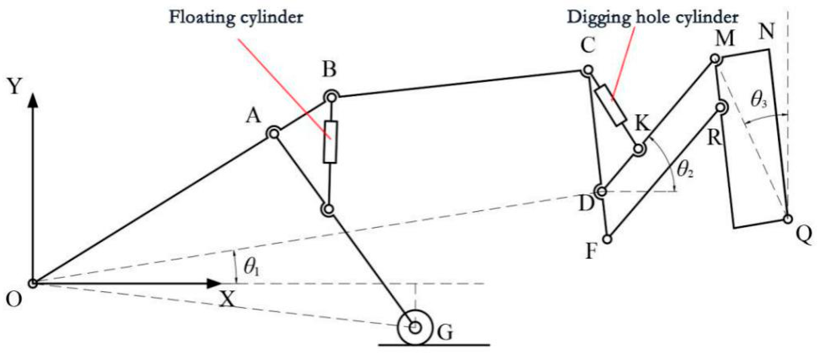
The intermittent digging mechanism is simplified into the planar linkage mechanism shown in Figure 2. For the tree planting machine digging hole mechanism motion analysis, for the cylinder and piston rod composition, the two constitute a mobile vice. Set the cylinder barrel and piston rod center of mass, as the mass does not change with the size of the oil feed, and the piston rod for the active part and, with a constant speed out and retracted, a four-bar mechanism for the parallel four-bar mechanism. The digging component and the cutter plate are equivalent to a fixed frame structure MNQR, and the parallel double digging cylinders are simplified to a single cylinder for analysis. The degrees of freedom of the mechanism are calculated as 2, according to the Chebyshev–Krupp formula.
The origin of the coordinate system is established at the traction point O, the traveling direction of the tree planter is the x-axis reversal, the lengths of the floating cylinder and the digging cylinder are used as the output of the mechanism motion, and the vector equation is established and transformed into the analytical form to find out the displacement trajectory of the digging cutter plate center point Q. LOA is the length of the connecting rod OA, and the lengths of the rest of the connecting rods and the distances between the various points are the same as this one. Set the angle between OD and the positive direction of the x-axis as θ1, the angle between the rod MD and the positive direction of the x-axis as θ2, and the angle between MQ and the positive direction of the y-axis as θ3, and the displacement trajectory of point Q can be obtained, as shown in Equation (1).
{ X Q = L O D cos θ 1 + L D M cos θ 2 + L M Q sin θ 3 + v 1 t Y Q = L O D sin θ 1 + L D M sin θ 2 + L M Q cos θ 3
Since the displacement trajectory of point Q is related to θ1, θ2, and θ3, it is also necessary to establish the connection between the floating cylinder and the digging cylinder with θ1, θ2, and θ3. From Figure 1, it can be obtained that
θ 1 = A O G A O D G O X
Since the relative position of each point of the frame is unchanged, A O D is a certain value, which can be obtained according to the formula of cosine theorem and sine theorem, as shown in Equations (3)–(6).
B A E = arccos L A B 2 + L A E 2 L B E 2 2 L A B L A E
L O G = L A O 2 + L A G 2 cos ( π B A E ) 2 L A O L A G
A O G = arccos L A O 2 + L O G 2 L A G 2 2 L A O L O G
G O X = arcsin L O G sin π 2 L O G y
From Figure 1, we can analyze the relationship between θ2 and the digging cylinder and floating cylinder, as shown in Equation (7).
θ 2 = π C D M C D O + θ 1
C D O is the intrinsic angle of the rack for a certain value, and according to the cosine theorem, it can be obtained that
C D M = arccos L C D 2 + L D K 2 L C K 2 2 L C D L D K
As can be seen in Figure 1,
θ 3 = M Q N + N Q Y
where M Q N is a constant value and N Q Y is the angle between NQ and the positive direction of the y-axis. From the fact that NQ is parallel to both MR and DF, it is obtained that
N Q Y = O D F O D Y
where O D F is the intrinsic angle of the frame and constant and is the angle between OD and the negative direction of the y-axis. O D Y = π 2 θ 1 .
In summary, the relationship between the displacement trajectory of the Q point of the rotating cutter disk and the displacement of the floating cylinder and the hole digging cylinder can be obtained. The first- and second-order derivatives of the displacement equation can be obtained from the speed and acceleration equations of the center point of the digging disk.

2.2. Mathematical Modeling of Electrohydraulic Servo Systems

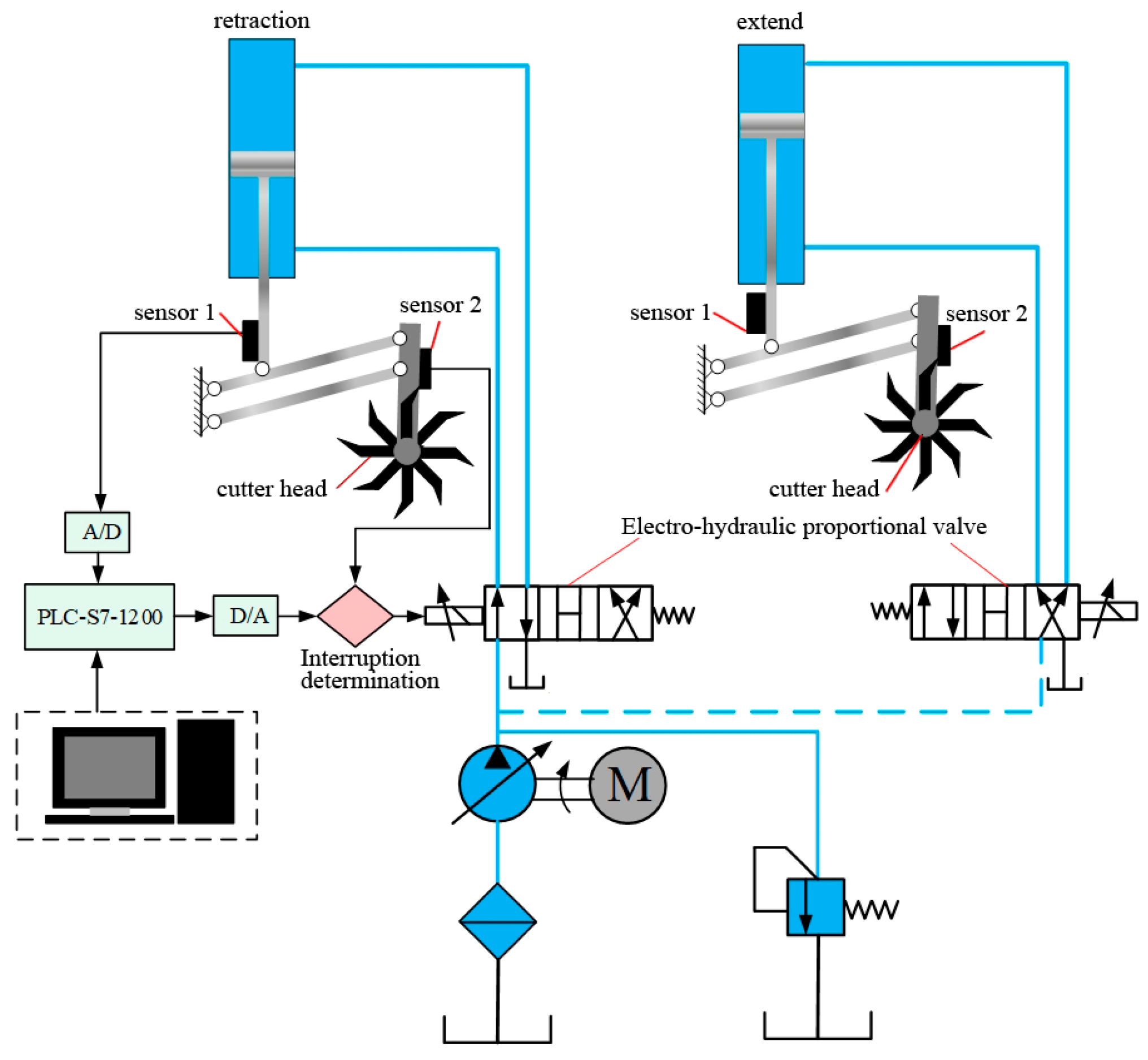
Tree planting spacing and planting depth is an important index for evaluating the quality of afforestation, and the electro-hydraulic position servo system controls the descent and rise of the digging cutter plate in the process of digging to realize the digging work, and its dynamic accuracy has a crucial impact on the spacing and hole shape. In the operation process, the floating cylinder supports the overall weight of the equipment, in order to ensure smooth operation, its running speed is slow, and it needs to have a large bearing capacity. The digging hole cylinder directly acts on the digging hole cutter plate, and the characteristics of the mechanism determine the small stroke of the cylinder can realize a large stroke of the cutter plate, and its dynamic performance on the planting depth and planting spacing has a critical impact. Therefore, it is of great significance to improve the dynamic and static performance of the hole digging cylinder electro-hydraulic position servo system. The hole digging system adopts dual position sensors, which are used as the state variable feedback and depth command feedback of the action cylinder, respectively. Because the unevenness of the terrain will make the actual digging depth produce different mapping effects, the depth command feedback can ensure that the depth of digging is consistent, according to the digging system to establish the system principle, shown in Figure 3.
As shown in Figure 3, digging holes in position sensor 1 feedback position information and input signals to control the dynamic performance of the system, position sensor 2 realize the interruption effect of the hydraulic actuator, and position sensor 2 will be in the specified time interval of digging holes in the depth of the quantitative collection, as when the amount of the hydraulic system outstretched is equal to the amount of the hole collection displacement, it will enable the hydraulic system to stop outstretched. Digging hole cylinders for a pair of asymmetric cylinders, with the use of electro-hydraulic proportional valves to control the movement of hydraulic cylinders, symmetric valve-controlled asymmetric hydraulic cylinders will lead to a different flow into the two chambers of the hydraulic cylinders and therefore do not apply to the traditional symmetric valve-controlled symmetric cylinder model, so in order to clarify the system in the process of digging holes and the dynamics of the mechanism model, establish the basic equations of the power mechanism of the four-way valve-controlled asymmetric hydraulic cylinders.
The electro-hydraulic proportional valve supporting the digging cylinder will control the axial movement of the spool according to the magnitude of the input current so that the hydraulic fluid flows into the hydraulic actuator. When the hydraulic actuator is extended, i.e., x p > 0 , according to the literature [25], the mathematical equations of the inlet and outlet flow of the electro-hydraulic proportional four-way valve are shown in Equations (11) and (12).
q 1 r = c d ω x v r 2 ρ ( P s P 1 )
q 2 r = c d ω x v r 2 ρ P 2
where cd is for the throttle port flow coefficient, ω is for the slide valve throttle window area gradient, and this study uses the whole circumference of the opening, which is ω = πd, d is for the spool diameter, xvr is for the spool opening amount, Ps is for the oil supply pressure, P1 is for the rodless cavity pressure, and P2 is for the rod cavity pressure.
If the proportional valve is not taken into account, there is implementation of the structure of the conditions of leakage into the hydraulic actuator two-cavity flow rate, respectively, as shown in Equations (13) and (14).
q 1 r = A 1 d x p d t + V 1 β e d P 1 d t
q 2 r = A 2 d x p d t + V 2 β e d P 2 d t
where xp is the hydraulic actuator outreach, βe is the hydraulic oil modulus of elasticity, V1 is the rodless chamber volume, V2 is the rod chamber volume, and A1 and A2 are the effective area of the rodless chamber and rod chamber of the hydraulic cylinder, respectively.
Therefore, according to Equations (11)–(14), further simplifications can be obtained as shown in the form of Equation (15).
q 1 r q 2 r = c d ω x v r 2 ρ ( P s P 1 ) c d ω x v r 2 ρ P 2 = A 1 d x p d t + V 1 β e d P 1 d t A 2 d x p d t + V 2 β e d P 2 d t
As shown in Equations (13) and (14), where V 1 β e d P 1 d t , V 2 β e d P 2 d t is the oil compression, and therefore, A 1 d x p d t > > V 1 β e d P 1 d t , A 2 d x p d t > > V 2 β e d P 2 d t . Set A 1 A 2 = n , so that Equation (15) can be further simplified to obtain the system oil supply pressure equation in the form shown in Equation (16).
P s = P 2 n 2 + P 1
The hydraulic pressure balance equation is shown in Equation (17), i.e., the output force generated by the load pressure in the left and right chambers is canceled out by the external load force, the acceleration of the load, and the friction damping.
A 1 ( P 1 1 n P 2 ) = m d 2 x p d t 2 + B p d x p d t + k x p + F t
As shown in Equation (17), the load pressure PL of the hydraulic actuator during extension is then shown in Equation (18).
P L = P 1 1 n P 2
According to the hydraulic actuator load pressure in Equation (18), the system oil supply pressure equation is shown in Equation (19).
P 1 = n 3 P L + P s n 3 + 1
Since the hydraulic actuator structure for the non-logarithmic form q1q2, the load flow qL = q1 and, combined with Equation (19), is further obtained by the electro-hydraulic proportional valve load flow nonlinear equation as shown in Equation (20).
q L r = c d ω x v r 2 ρ n 3 n 3 + 1 ( P s P L )
Linearization of the electro-hydraulic proportional valve load flow is obtained as shown in Equation (21).
q L r = K q r x v r K c r P L
where K q r = q L r x v = c d ω 2 ρ n 3 n 3 + 1 ( P s P L ) , K c r = q L r P L r = c d ω x v 2 ρ n 3 n 3 + 1 ( P s P L ) 2 ( P s P L ) .
The initial volume of the upper chamber of the hydraulic cylinder is set to Vt, then the volume of the left chamber V1 when the hydraulic cylinder is extended as shown in Equation (22).
V 1 = V t + A 1 x p
Combining Equations (19) and (22), the flow continuity equation for the asymmetric hydraulic cylinder is obtained as shown in Equation (23).
q L r = v t β e n 3 n 3 + 1 d P L d t + A 1 β e n 3 n 3 + 1 d P L d t x p + A 1 d x p d t
Bringing the load pressure of Equation (18) into Equation (17), the hydraulic system force balance equation is obtained as shown in Equation (24).
A 1 P L = m d 2 x p d t 2 + B p d x p d t + K x p + F t
where m is the load mass, Bp is the viscous friction damping coefficient, K is the load stiffness coefficient, and Ft is the interference force.
From Equations (21) and (23), the form shown in Equation (25) is obtained.
K q x v r = ( v t β e n 3 n 3 + 1 + A 1 β e n 3 n 3 + 1 x p ) d P L d t + A 1 d x p d t + K c P L
Set V t β e n 3 n 3 + 1 + A 1 β e n 3 n 3 + 1 x p = C r , where C r is the time-varying bounded parameter, and the specific value is determined by x p . Combining Equations (24) and (25), the differential equation of the system is obtained in the form shown in Equation (26).
K q x v r = C r m A 1 d 3 x p d t 3 + ( K c m A 1 + C r B p A 1 ) d 2 x p d t 2 + ( K C r A 1 + B p K c A 1 + A 1 ) d x p d t + K K c A 1 x p + C r F t A 1 + K c F t A 1
Set x p = x 1 , d x p d t = x 1 = x 2 , d 2 x p d t 2 = x 2 = x 3 , then Equation (26) can be simplified to the form shown in Equation (27).
x 3 = ( K c r C r + B p m ) x 3 ( K m + B p K c r C r m + A 1 2 C r m ) x 2 K K c r C r m x 1 + A 1 K q r C r m x v r C r F t A 1 K c r F t A 1
Set ( K c C r + B p m ) = a 1 , ( K m + B p K c C r m + A 1 2 C r m ) = b 1 , K K c C r m = c 1 , A 1 K q C r m = d 1 , C r F t A 1 K c F t A 1 = f 1 , then Equation (27) is further expressed in the form shown in Equation (28).
x 3 = a 1 x 3 + b 1 x 2 + c 1 x 1 + d 1 x v r + f 1
Then, the state space equation of the system is obtained from Equation (28) as shown in Equation (29).
[ x 1 x 2 x 3 ]   =   [ 0 1 0 0 0 1 c 1 b 1 a 1 ] [ x 1 x 2 x 3 ] + [ 0 0 d 1 ] x v r + [ 0 0 f 1 ]
Similarly, as shown in Figure 3, when the hydraulic actuator is retracted, i.e., x p < 0 , the mathematical equations for the inlet and outlet oil flow of the electro-hydraulic proportional four-way valve are shown in the form of Equations (30) and (31).
q 1 s = c d ω x v r 2 ρ ( P s P 2 )
q 2 s = c d ω x v r 2 ρ P 1
Execution then into the hydraulic actuator two-chamber flow rate is shown in Equations (32) and (33).
q 1 s = A 2 d x p d t + V 2 β e d P 2 d t
q 2 s = A 1 d x p d t V 1 β e d P 2 d t
From Equations (30)–(33), then obtain the form shown in Equation (34).
c d ω x v 2 ρ ( P s P 2 ) c d ω x v 2 ρ P 1 A 2 A 1
Thus, Equation (34) can be further simplified to obtain the system oil supply pressure equation in the form shown in Equation (35).
P s = P 2 + P 1 n 2
The hydraulic actuator hydraulic pressure balance equation is then shown in the form of Equation (36).
A 2 ( P 2 n P 1 ) = m d 2 x p d t 2 + B p d x p d t + K x p + F t
The load pressure PL of the hydraulic actuator during retraction is shown in Equation (37).
P L = P 2 n P 1
Therefore, the load flow rate of the electro-hydraulic proportional valve is obtained after linearization as shown in Equation (38).
q L s = K q s x v s K c s P L
where K q s = q L r x v , K c s = q L r P L r .
The initial volume of the lower chamber of the hydraulic cylinder is set to Vt, then the lower chamber volume V2 when the hydraulic cylinder retraction is shown in Equation (39), and then the flow continuity equation shown in Equation (40).
V 2 = V t + A 2 x p
q L s = A 2 d x p d t + ( V t + A 2 x p β e 1 n 3 + 1 ) d P L d t
Let C s = ( V t + A 2 x p β e 1 n 3 + 1 ) , from Equations (36)–(40), which can be obtained from the system retraction with the differential equation, as shown in Equation (41).
K q x v s = C s m A 1 d 3 x p d t 3 + ( K c s m A 2 + C s B p A 2 ) d 2 x p d t 2 + ( K C s A 2 + B p K c s A 2 + A 2 ) d x p d t + K K c s A 2 x p + C s F t A 2 + K c s F t A 2
Let x p = x 1 , d x p d t = x 1 = x 2 , d 2 x p d t 2 = x 2 = x 3 , then Equation (41) can be simplified to the form shown in Equation (42).
x 3 = ( K c s C s + B p m ) x 3 ( K m + B p K c s C s m A 2 2 C s m ) x 2 K K c s C s m x 1 + A 2 K q s C s m x v r C s F t A 1 K c s F t A 1
Let ( K c s C s + B p m ) = a 2 , ( K m + B p K c s C s m A 2 2 n C s m ) = b 2 , K K c s C s m = c 2 , A 1 K q s C s m = d 2 , C s F t A 1 K c F t A 1 = f 2 , then Equation (42) is further expressed in the form shown in Equation (43).
x 3 = a 2 x 3 + b 2 x 2 + c 2 x 1 + d 2 x v s + f 2
Then, the state space equation of the system is obtained from Equation (43) as shown in (44).
[ x 1 x 2 x 3 ]   =   [ 0 1 0 0 0 1 c 2 b 2 a 2 ] [ x 1 x 2 x 3 ] + [ 0 0 d 2 ] x v r + [ 0 0 f 2 ]
According to the state controllability criterion as shown in Equation (45), the system is controllable.
R a n k ( [ B       A B       A 2 B ] ) = ( 0 0 d 0 d a d d a d d ( b + a 2 ) ) = 3
Shown in Equations (29) and (44) are the state-space equations for the hydraulic actuator system extending and retracting, respectively, where the input is the spool displacement and the output is the piston rod displacement. Electro-hydraulic proportional valve internal proportional solenoid, according to the input voltage signal, produces a response action with the work of spool displacement. Therefore, the mathematical model of the electro-hydraulic proportional valve is shown in Equation (46).
x v = K v u r
where Kv is the proportional gain, xv is the spool displacement of the proportional valve, and ur is the input voltage signal of the proportional valve.
The displacement sensor will generate the corresponding voltage value according to the actual displacement, so the displacement sensor mathematical model is shown in Equation (47).
u x = K x x p
where Kx is the displacement sensor feedback gain, xp is the hydraulic cylinder displacement, and ux is the feedback voltage signal.

2.3. Design of Linear State Feedback Controller with Feedforward Based on a Linear Quadratic Regulator

The time–domain curves of the hydraulic system show that the actuator exhibits different dynamic performance during extension and retraction. The main reason is the servo valve flow pressure coefficient of the different and actuator structure caused by the linear and nonlinear factors. For the linear performance of the servo valve flow changes and actuator volume differences, with the implementation of the structure of the process of the proportional valve flow and pressure coefficients for K q r = q L r x v , K c r = q L r P L r , and vice versa, the flow and pressure coefficients for K q s = q L r x v , K c s = q L r P L r and the actuator in different operating conditions, the volume of the two chambers and the rate of change of the volume are not the same. The nonlinear factors mainly reflect the compression performance of the fluid, specifically
C s = V t β e 1 n 3 + 1 + A 2 x p β e 1 n 3 + 1 = C s r + A 2 x p β e 1 n 3 + 1 ,   C r = v t β e n 3 n + 1 + A 1 x p β e n 3 n + 1 = C r c + A 1 x p β e n 3 n + 1 ,
which is affected by the displacement factor of the actuator, i.e., with the increase in the displacement of the actuator structure, the value of this parameter will also be increased.
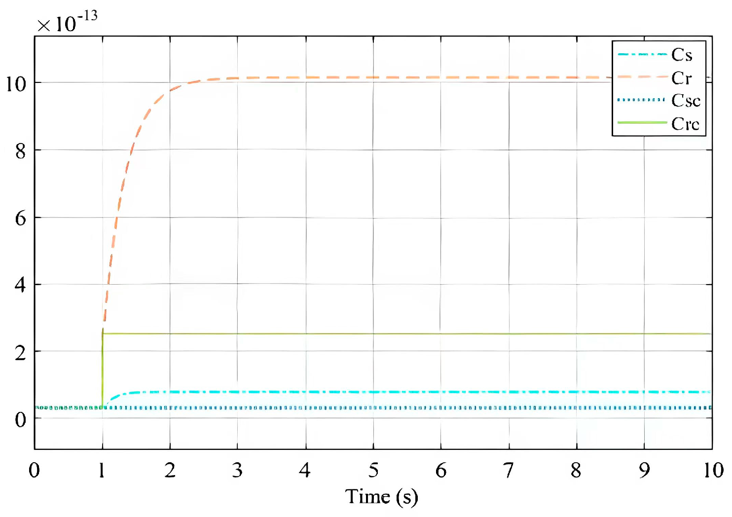
In order to clarify the system flow compressibility of the actuator performance impact, when the system extends and retracts the maximum stroke, Cr, Crc, Cs, are Csc are the time domain change curves shown in Figure 4.
When the system extends, the change curve of Cr is [2.54 × 10⁻¹³, 1.016 × 10⁻¹²], and the change curve of Cs is [3.2 × 10⁻¹⁴, 7.94 × 10⁻¹⁴]. According to the variation value curve, it can be seen that this value is small and the range of variation of this parameter is large when the hydraulic system extends, while the variation of this value is small when it retracts. In order to further clarify whether this parameter has a large effect on the dynamic performance of the hydraulic system, the time domain curves of the system under the conditions of Cr, Crc, Cs, and Csc were analyzed separately.
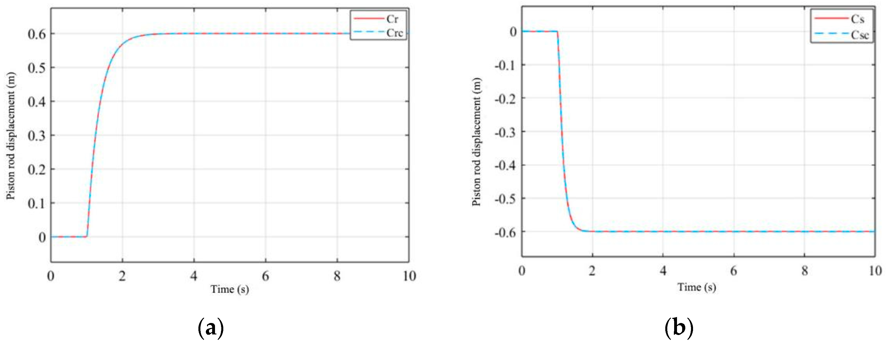
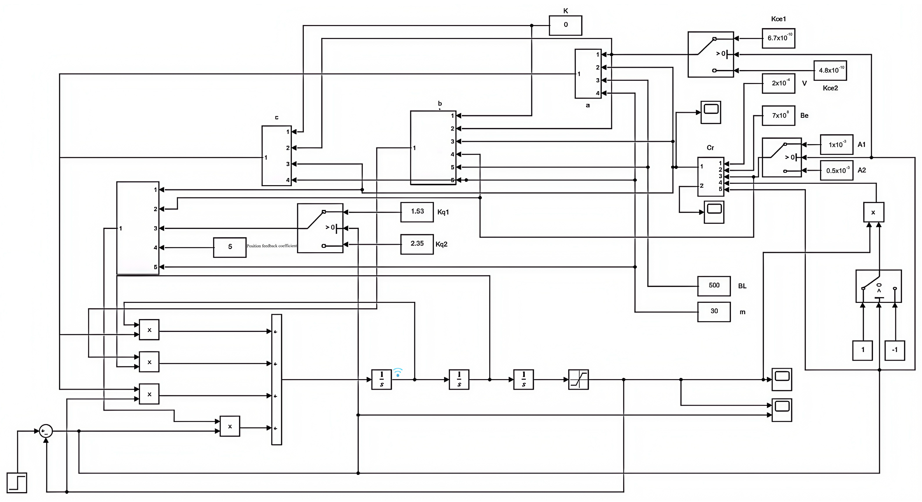
As shown in Figure 5, the time-varying parameters Cr and Cs on the asymmetric hydraulic system have less impact; that is, the volume change caused by the piston movement leads to the compressibility of the hydraulic oil and will not have a greater impact on the dynamic performance of the system, so C r = C r c , C s = C s c can be considered as a constant form and the system as a linear constant system. Therefore, the Simulink simulation model of the simplified system is shown in Figure 6.
To design a linear state feedback controller with feedforward, the equilibrium point is used as an important basis. When the state variable of the hydraulic actuator deviates from the equilibrium point, it will not be able to return to the equilibrium point again without external adjustments, and therefore, the system can be considered unstable. Therefore, if the deviation from the equilibrium point is changed, it is necessary to design a suitable control input ur to bring the system back to the equilibrium point, and according to Section 2.2, it is known that the system is a controllable system.
According to the system, Equations (28) and (43) combined with Equations (46) and (47) can be obtained as shown in Equation (48) as the system differential equation.
u x = a u x + b u x + c u x + K x K v d u r + K x f
Let u x = x 1 , u x = x 1 = x 2 , then Equation (48) can be written in the form of a state space equation as shown in (49).
{ x 1 = x 2 x 2 = x 3 x 3 = a x 3 + b x 2 + c x 1 + K x K v d u r + K x f
It can be made that xd is the stabilizing equilibrium point of the system, then the error e of the system can be known as shown in Equation (50).
e ( t ) = x d x 1
From Equation (50), further, e ( t ) , e ( t ) , e ( t ) , can be obtained as shown in Equations (51)–(53)
e ( t ) = x d x 2
e ( t ) = x d x 3
e ( t ) = x d x 3
Bringing Equations (51)–(53) into (49), then the state space matrix is obtained as shown in Equation (54), where error e is used as the system state variable.
[ e e e ] = [ 0 1 0 0 0 1 c b a ] [ e e e ] + [ 0 0 K x K v d ] u r + [ 0 0 x d a x d b x d c x d + f ]
This system state space matrix when e ( t ) = 0 , e ( t ) = 0 , e ( t ) = 0 , then e is shown in Equation (55).
e = x d a x d b x d c x d + f c
In order to make the hydraulic system t→∞, e = 0 , it is necessary to establish the feedforward control, i.e., the equilibrium point of the system, is shifted to xd. Then, the control equation apparatus equation of the system is established as shown in Equation (56).
u r = [     k 1         k 2       k 3 ] [ e e e ] + 1 K x K v d ( x d a x d b x d c x d + f )
The control strategy consists of a feedforward part 1 K x K v d ( x d a x d b x d c x d + f ) and a linear feedback part [     k 1         k 2       k 3 ] [ e e e ] .
Bringing Equation (56) into the system state space matrix (54) yields the form shown in (57).
[ e e e ] = [ 0 1 0 0 0 1 c K x K v d k 1 b K x K v d k 2 a K x K v d k 3 ] [ e e e ] = A [ e e e ]
In order to stabilize the hydraulic system, it should be ensured that the characteristics of this matrix λ = [     λ 1         λ 2       λ 3 ] < 0. Therefore, this condition can be satisfied by choosing the appropriate K = [     k 1         k 2       k 3 ] . However, k affects the response speed of the hydraulic system, the positional accuracy, and the acceleration of the state variables. Therefore, in this paper, parameter selection is carried out through optimal control theory. It is shown that the system can be approximated as a third-order constant linear system, so a linear quadratic regulator (LQR controller) is used to design the feedback control K. The optimal control theory introduces a cost function such as K, which can be used to control K. The cost function is introduced according to the optimal control theory as shown in Equation (58).
J = 0 z T ( t ) Q z ( t ) + u T ( t ) R u ( t ) d t
The principle of the LQR controller is mainly to change the eigenvalues of the matrix A by choosing a reasonable K = [     k 1         k 2       k 3 ] and ensure that the cost function J minimum value, where Q and R are the weight matrices of the state variables and control quantities, respectively, and are positive definite symmetric matrices. From matrix A, it is clear that the system is been input, and the system is a third-order system, so that can be set as Q = [ q 1 0 0 0 q 2 0 0 0 q 3 ] , R = r.
Therefore, Equation (58) is further reduced to the form shown in Equation (59).
J = 0 q 1 x 1 2 ( t ) + q 2 x 2 2 ( t ) + q 3 x 3 2 ( t ) + r u r 2 ( t ) d t
Different weight coefficients will have different effects on the cost function and the system; that is, when the input weight coefficients are larger, the cost function in the solution over the city will pay more attention to the change of ur, and when q1 is larger, then the system will pay attention to the change of position can be in the shortest possible time to converge to 0. In this study, due to the hydraulic system to drive the cutter plate digging holes, digging holes in the process of the hole type is more important to the speed of the change; therefore, this study will pay more attention to q2, i.e., e = 0 , to realize the acceleration of the system in the shortest time tends to 0, i.e., the speed error, i.e., to ensure the stability of the system speed output. However, the hydraulic system in the retraction process is the more important position accuracy and response speed; that is, the position error in a faster time to make e = 0.

3. Results and Discussion

3.1. Electro-Hydraulic Servo System Performance Analysis

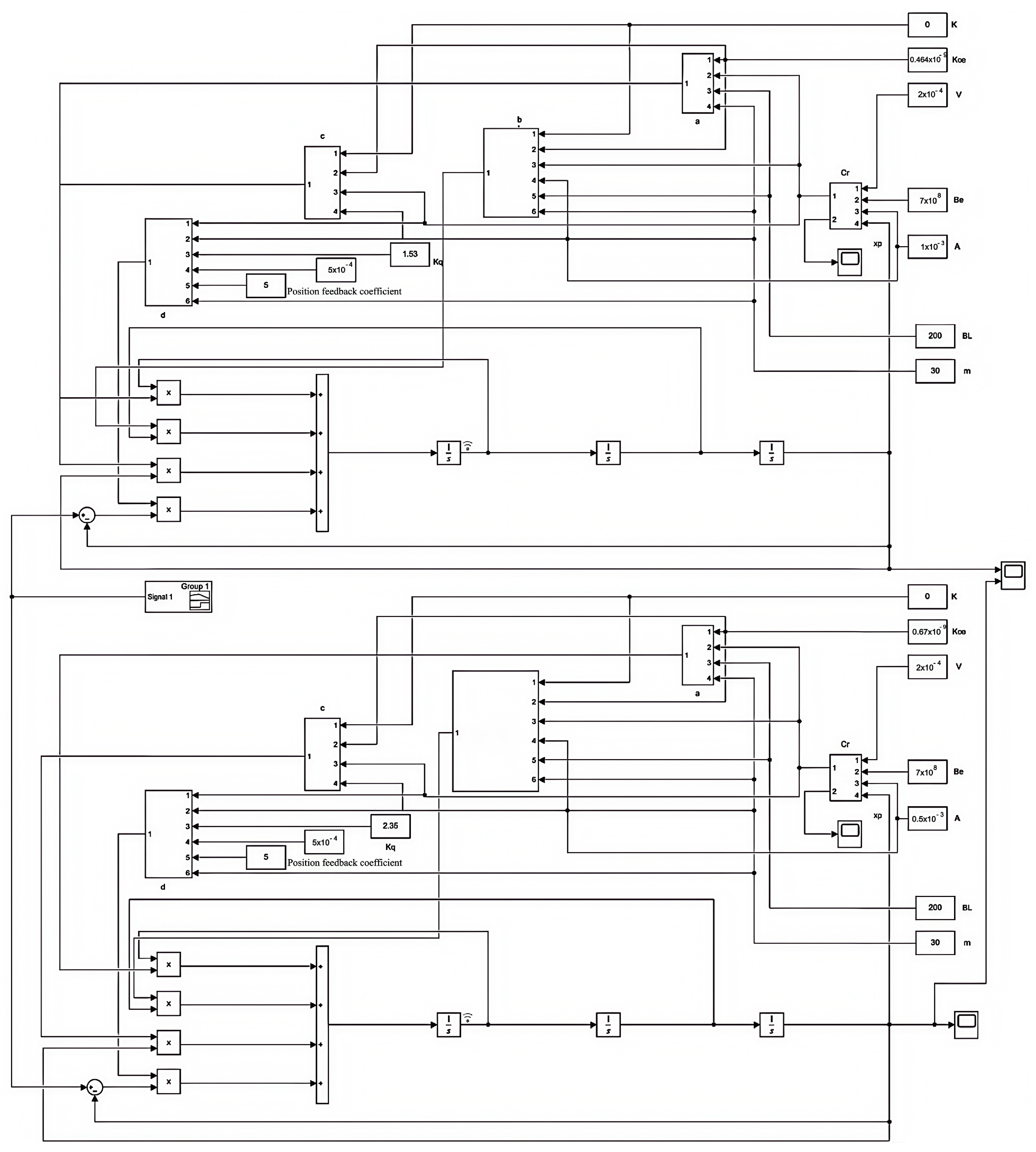
The dynamic and static performance of the hydraulic system plays a crucial influence effect on the accuracy of digging holes. Therefore, in order to clarify the dynamic performance index of the hydraulic system in the process of digging holes, the Simulink simulation model of the system is established, and the step and sinusoidal excitation signals are used to analyze the performance index of the hydraulic system in the operation process. During the model development process, we utilized Simulink 2022a software and Windows 11 operating system for model construction. To enhance the simulation efficiency, the system employed a variable-step solver for simulation calculations, which effectively reduces the simulation time. The maximum step size is set to automatic mode, corresponding to 1/50 of the simulation time duration. Due to the hole shape in the hole digging process as an important indicator requirement, it ensures that the hydraulic actuator has a better operating accuracy, so the hydraulic system adopts the position closed-loop form. The specific parameters of the hydraulic system are shown in Table 1, and the simulation model of the asymmetric hydraulic system is shown in Figure 7, which models the outstretching and retracting process of the hole digging cylinder separately to clarify the stroke operation performance of the hydraulic position system.
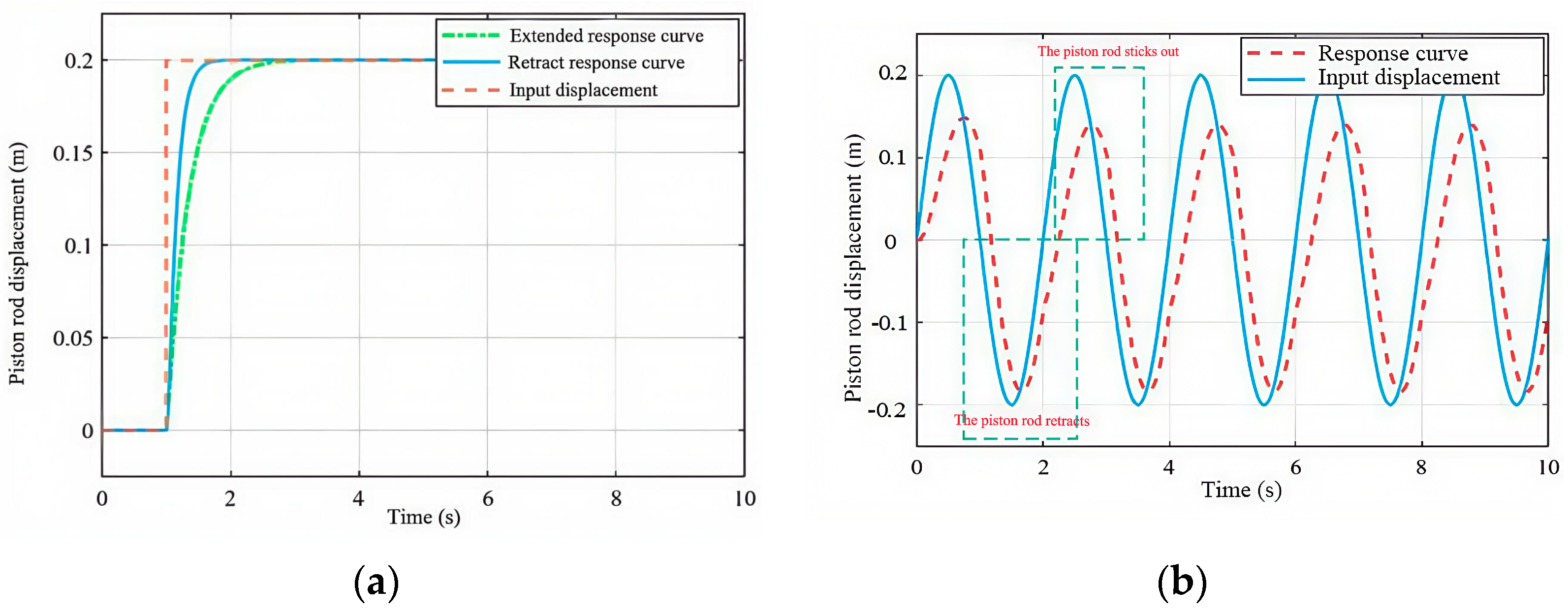
When the input step signal of the hydraulic actuator system is 1 V, i.e., the actuator output stroke of the hydraulic system is 0.2 m, the time domain curves of the step and sinusoidal responses of the hydraulic system under the same stroke of extension and retraction are shown in Figure 8.
As shown in Figure 8a, the hydraulic system under the same stroke condition reaches the steady state when retracting for 2 s, while the hydraulic system reaches the steady state when the system reaches the steady state for 3.5 s. There is no overshoot in the hydraulic system working process, so it shows that the system belongs to the overdamped system, but the response speed of the system in the process of reaching out is faster, and the steady state time is longer, which should ensure that the speed is stabilized by about 0.08 m/s within 0.2~0.35 m, while the system in the process of retracting back the system’s response speed is slower, and the steady-state time is longer. When the system uses sinusoidal signals, the amplitude attenuation phenomenon in the retraction process of the hydraulic system is significantly smaller, and the two appear as obvious phase lag phenomenon, so it should be necessary to design a reasonable control strategy to improve the dynamic performance of the system.

3.2. Simulation and Analysis of a Hydraulic System Based on LQR Linear State Feedback Control with Feedforward

A linear quadratic regulator (LQR) is a powerful control method suitable for optimizing the performance of hydraulic systems. Based on mathematical optimization theory, it employs a comprehensive feedback control strategy that utilizes state information from the hydraulic system to achieve fast stability, robustness, and optimized performance metrics such as response speed and stability. LQR uses a quadratic cost function, where a weighting matrix balances state variables and inputs, achieving optimal control effects. Therefore, LQR effectively enhances the control performance of hydraulic systems, enabling them to perform exceptionally well in various applications.
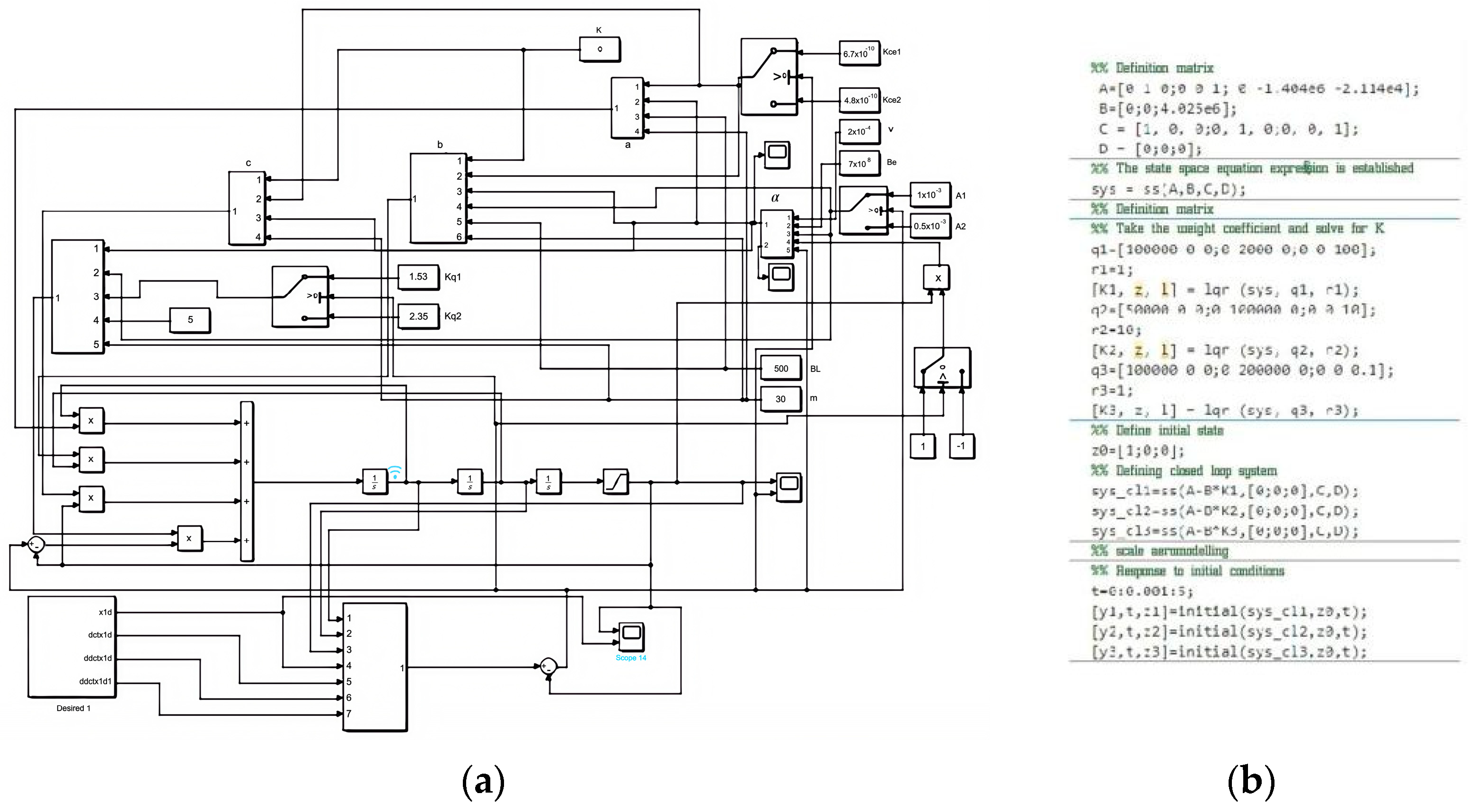
The LQR controller is to ensure that Jmin is obtained by selecting the appropriate K under the condition of λ = [     λ 1         λ 2       λ 3 ] < 0, since the acceleration should be made to converge to 0 faster than the velocity during the process. Therefore, it should be ensured that q2 > q3 and q2 > q1. However, the hydraulic system should be ensured that the piston rod returns quickly during the return process, so then q1 > q3 and q1 > q2. Therefore, the simulation model of the hydraulic system based on the LQR with feedforward for linear state feedback control and the code of the LQR computational gain K are constructed as shown in Figure 9a,b.
When the condition of external disturbance force of the system is not considered, then the data in Table 1 are brought into the system state in Equation (49) during the system reaching out, then the system state matrix is obtained as shown in Equation (60).
[ x 1 x 2 x 3 ]   =   [ 0 1 0 0 0 1 0 1.404 × 10 6 2.114 × 10 4 ] [ x 1 x 2 x 3 ] + [ 0 0 4.025 × 10 6 ] u v r
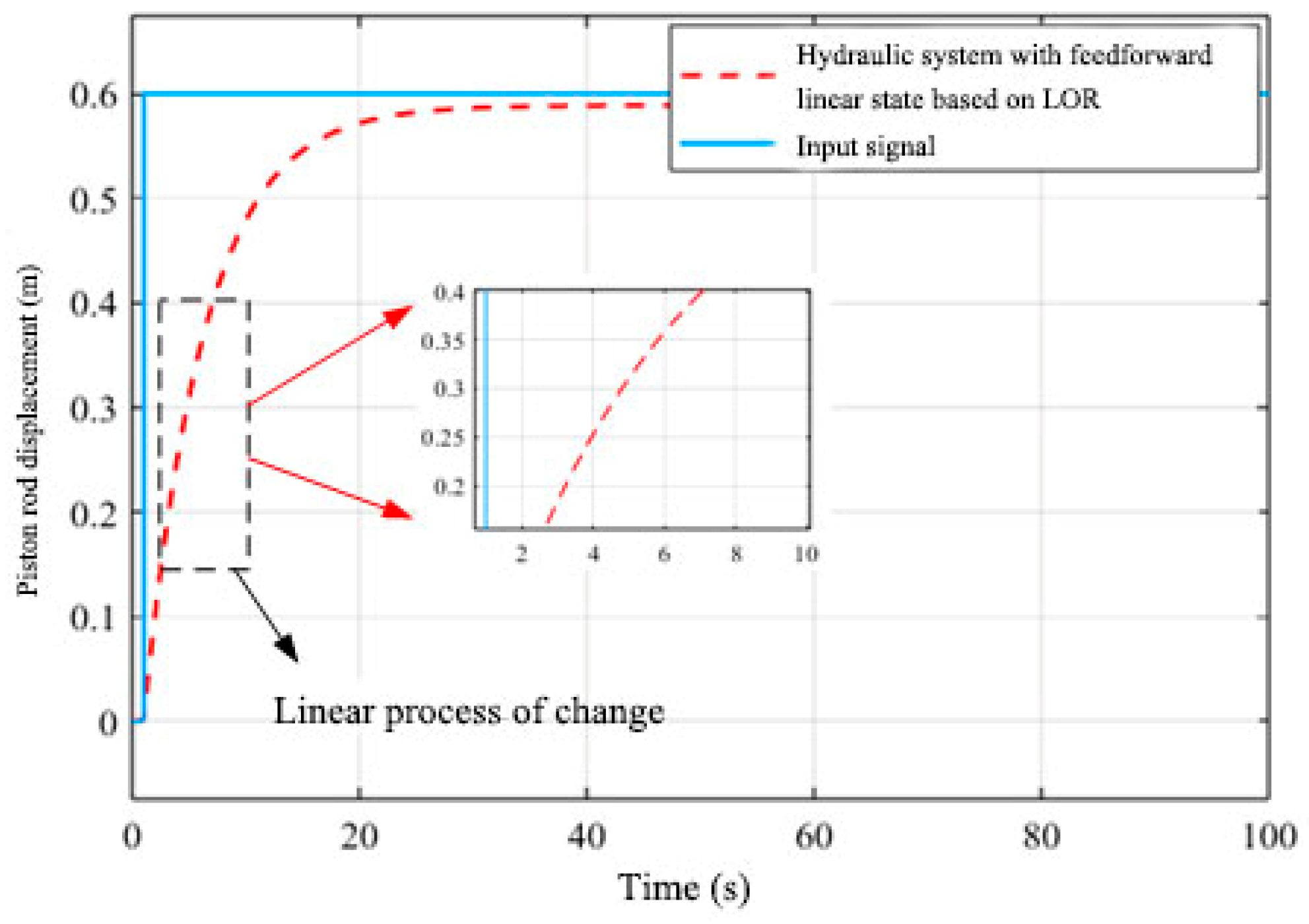
When the hydraulic actuating system is extended, then the constant velocity of the system is used as an evaluation index, i.e., a short period of time to achieve e = 0 , then set the state cost matrix Q = [ 3000 0 0 0 100000 0 0 0 1 ] , which shows that the velocity weights q2 >> q3 and q2 >> q1. Set the input cost matrix R = 1, which shows that the smoothness of the higher position and velocity is achieved at a smaller input cost, then obtain K = [     54.77       316.245       0.9959 ] . Thus, the time domain response curve of the system under the step response condition of the hydraulic system is obtained as shown in Figure 10.
As shown in Figure 10, comparing the pure closed-loop feedback system as in Figure 8a, using the LQR linear state feedback control strategy with feedforward, the system reaches a steady state in 30 s, while the steady-state time of the pure position closed-loop loop is 3.5 s, and its velocity ranges from 0.073 to 0.083 m/s at 0.2~0.35 m. The position of the corrected system is able to ensure 0~0.4 m in the position extension process, can ensure that the range of 0~0.4 m shows a linear outstretching trend, and the outstretching distance of the digging cylinder in the planting system is 0~0.35 m, so it is possible to ensure that the linear change can be satisfied within the stroke. The specific displacement of the digging cylinder is determined by the flywheel displacement sensor, which can realize the interruption effect.
The system in the retraction process should ensure that the position in a short period of time quickly returns to ensure the flywheel in a short period of time for energy storage, then set the state cost matrix Q = [ 100000 0 0 0 10 0 0 0 10 ] , which indicates that the velocity weights q1 >> q2 and q1 >> q3. Setting the input cost matrix, R = 1, it is shown in the smaller input cost to achieve the position of the output volume to quickly reach a steady state. When the condition of external disturbance force of the system is not considered, then the data in Table 1 are brought into the system state in Equation (49) during the system return process, then the system state matrix is obtained as shown in Equation (61).
[ x 1 x 2 x 3 ]   =   [ 0 1 0 0 0 1 0 0.5625 × 10 6 1.50 × 10 4 ] [ x 1 x 2 x 3 ] + [ 0 0 3.6 × 10 6 ] u v s
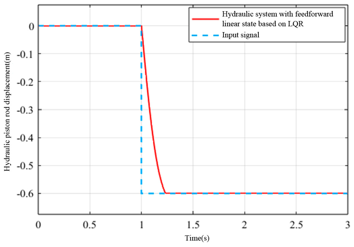
The system feedback parameters K = [     305.1356       10.3712       3.0451 ] can be known by LQR. Thus, the time domain response curve of the system under the hydraulic system step response condition is obtained as shown in Figure 11.
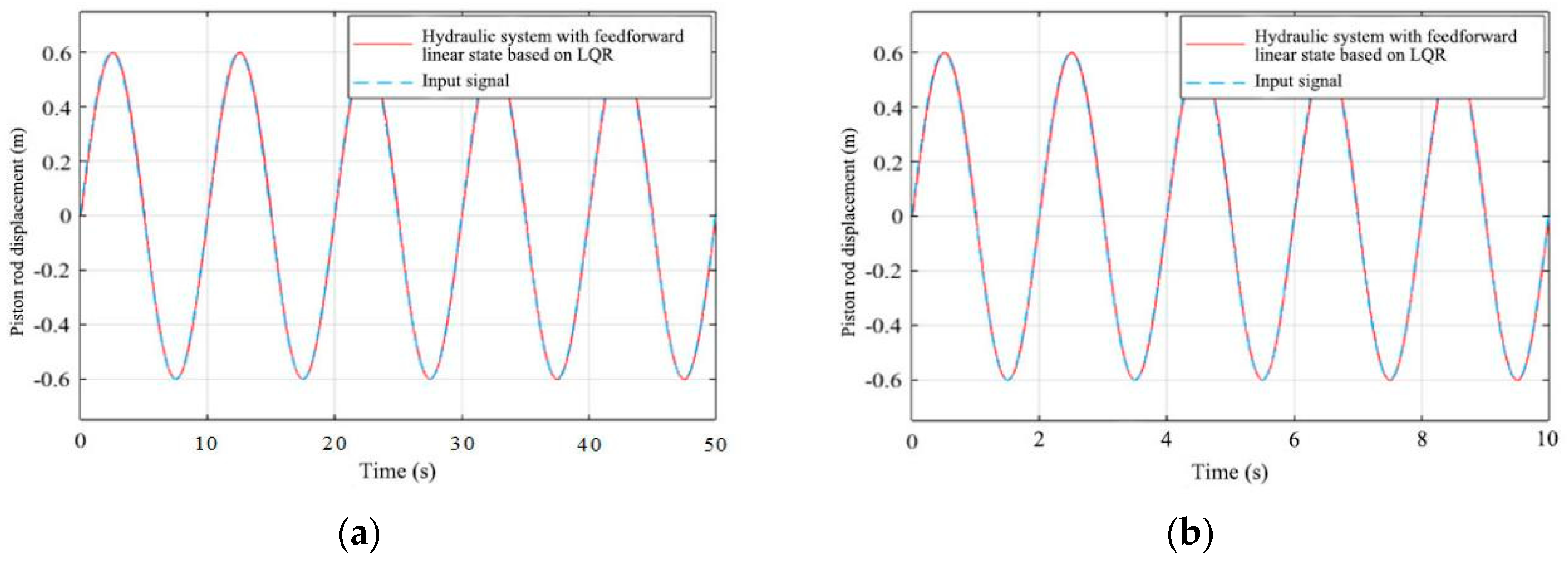
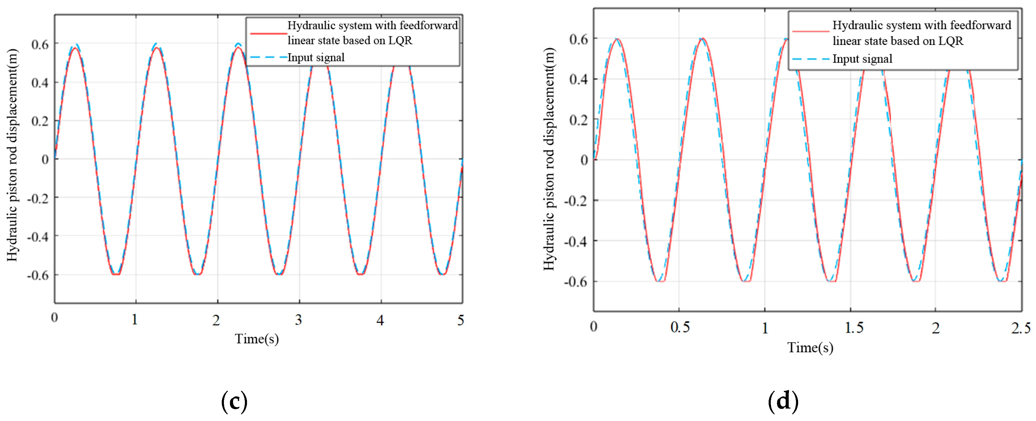
As shown in Figure 11, comparing the pure closed-loop loop feedback system as in Figure 12b, the speed of the system is significantly improved by using the linear state feedback control strategy of LQR with feedforward, and the system reaches the steady state in 1.2 s, while the steady-state time of the pure positional closed-loop loop is 2 s, and its rapidity is improved by 40%. To clarify the tracking performance of the system, a sinusoidal signal is used as the excitation signal of the system, then the sinusoidal response curve of the system is obtained as shown in Figure 12.
As shown in Figure 12, it can be seen that the system has better dynamic performance when it works at a low frequency, and when the system working frequency is greater than 1 Hz, the system will have obvious phase lag and the phenomenon of a flat top in amplitude. However, the digging process is a low-frequency process, so the simulation results show that the control strategy based on the LQR linear state feedback control with feedforward can meet the actual system requirements.

3.3. Experiments on a Hydraulic System Based on LQR Linear State Feedback Control with Feedforward

The composition structure of the electro-hydraulic position servo system of the digging cylinder is shown in Figure 13, which is mainly composed of two subsystems: electrical and hydraulic. The hydraulic system has flexible links such as mechanical fixed connection stiffness and load stiffness. Research indicates that the surface soil layer and the subsoil layer exhibit different density ranges and hardness indicators. The specific parameters are as follows: the moisture content of the surface soil layer is 12.98%, the soil density is 1.42 g/cm3, the soil firmness is 1415 Pa, and the soil Poisson’s ratio is 0.34; the moisture content of the subsoil layer is 16.12%, the soil density is 1.73 g/cm3, the soil firmness is 1652 Pa, and the soil Poisson’s ratio is 0.41. To simulate the excavation process in an actual hydraulic system, this study used a variable stiffness elastic plate to describe the external forces acting on the hydraulic system during the experiment. In the initial compression phase of the excavation process, the reaction force generated by the elastic plate is relatively small. As the hydraulic system continues to output, the reaction force gradually increases. This design better simulates the stress conditions of the soil in real engineering scenarios. The industrial control machine will control the signal through the data acquisition card and D/C module, the digital signal into a voltage signal, and the servo amplifier will be the input voltage signal into the current signal to drive the electro-hydraulic servo valve and then drive the electro-hydraulic servo valve work. The position sensor will feed back the actual position signal of the load to the servo valve amplifier, and through the data acquisition card and C/D module, the position signal will be converted into a digital signal and transmitted back to the computer, thus forming a closed-loop control. The servo amplifier consists of three parts: power amplifier circuit, speed feedback, and oscillation circuit. It adopts the current parallel negative feedback working principle, which can provide a linear output of ±5 V → ±40 mA, and at the same time, it provides a quiver signal to work together, and the amplitude of the quiver signal can be continuously adjusted between 0 V and the supply voltage, and the frequency of the quiver can be adjusted continuously between 50 Hz and 1000 Hz. The industrial controller utilizes Real-time Workshop (RTW), a real-time workspace in the MATLAB and Simulink environment, to control the hydraulic control system. A check mechanism is maintained between the Simulink model and the real-time application program, and the real-time kernel determines whether the structure of the Simulink model is the same as the structure of the real-time application program in the process of code generation. The structure of the Simulink model is consistent with that of the real-time application during code generation. In the process of model construction, Simulink 2014a software and Windows 10 operating system were used for model construction. Due to the need to generate a real-time code, a fixed-step solver was used in the simulation calculations. In this case, since there is no error control mechanism, and in order to meet the solution accuracy of the system, the step size of the fixed-step solver is set to 0.01.
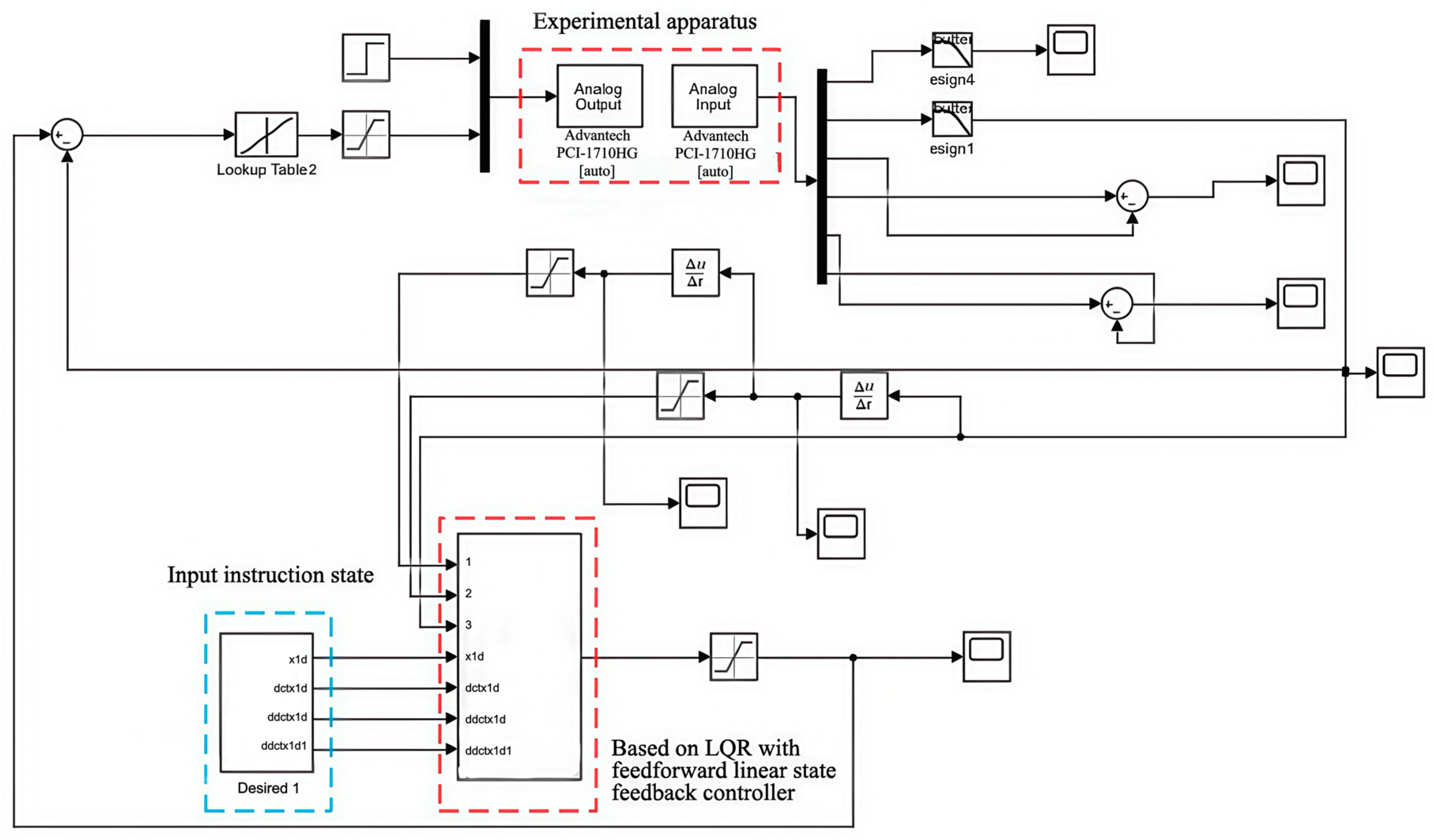
In order to clarify the practical application effect of the designed control strategy, the designed control strategy is imported into the host computer, and the sinusoidal and step response are used as the excitation signals, then the experimental model of the host computer is shown in Figure 14, which mainly consists of two parts: the control algorithm module and the controlled object. The experimental module is divided into Analog Output and Analog Input, of which Analog Output is the hydraulic system input command unit, and Analog Input is the actual hydraulic system state feedback information module.
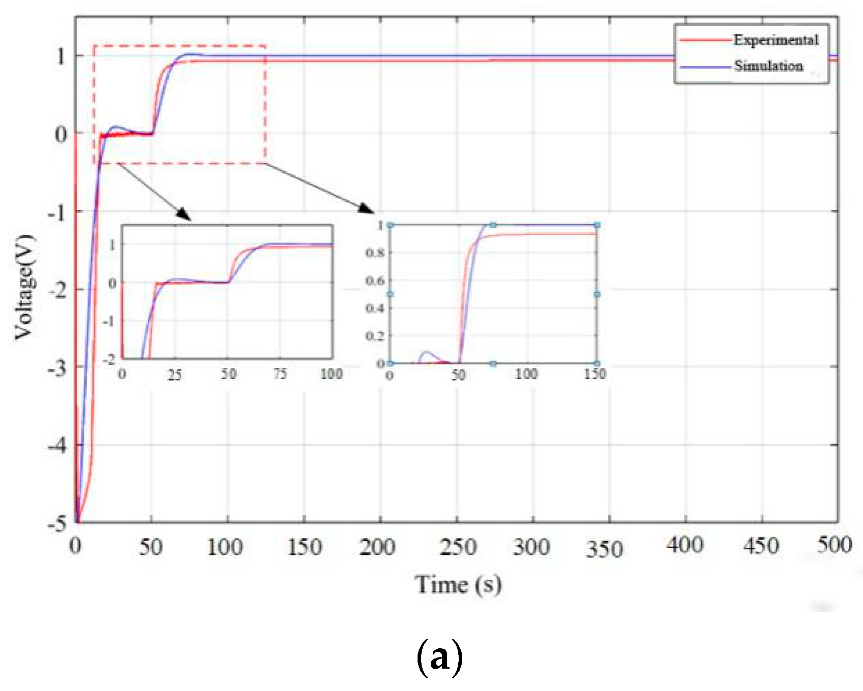
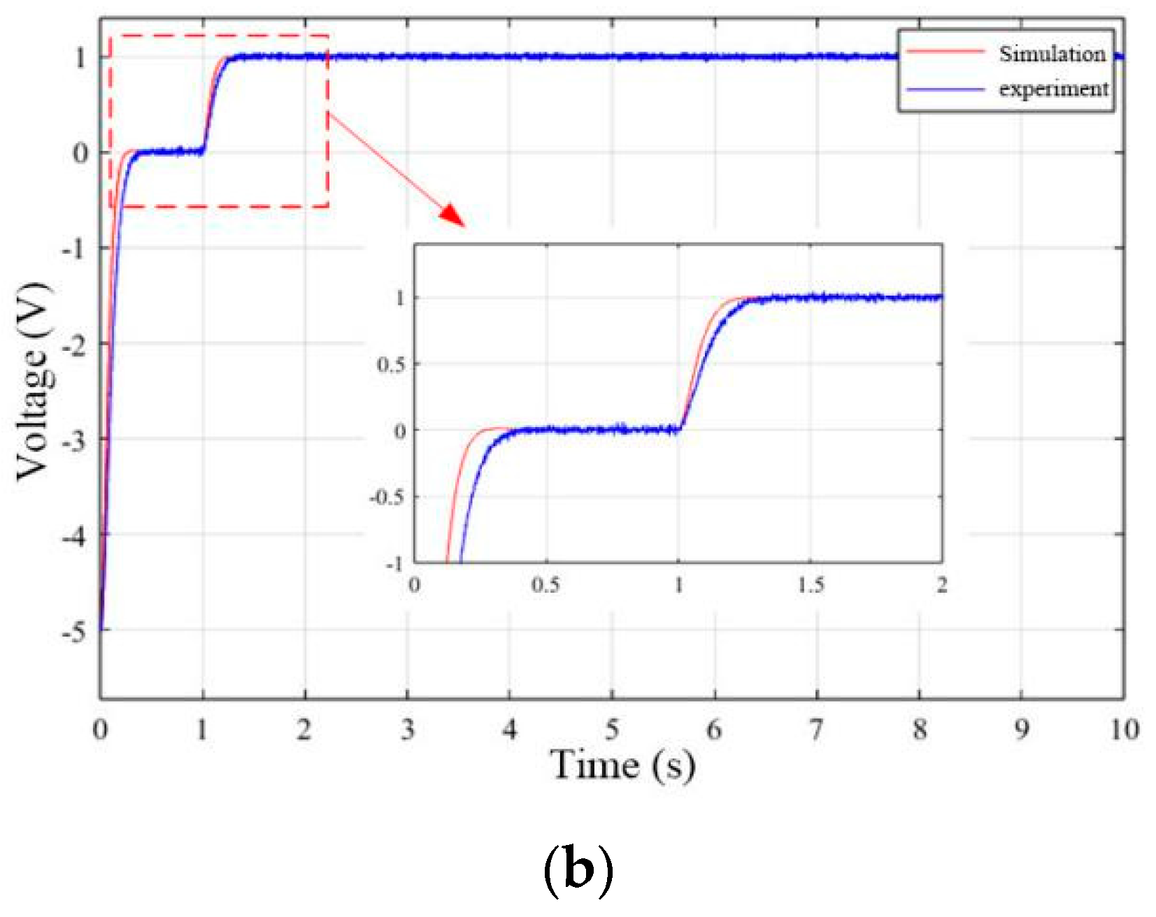
When the system extends, the process should ensure that the position accuracy to meet the conditions of the system speed should have high stability, in order to verify the effectiveness of the control strategy for the step response test, in which the step response curve is shown in Figure 15. When the system extends the command to 1 V, the actual output is 0.6 m. As shown in Figure 15a, the comparison of the simulation and experimental time domain curves shows that there is a difference between the simulation and the experiment, but the error is less than 10%, which indicates that the control strategy can effectively improve the dynamic performance of the system. When 50~58.6 s, the hydraulic system is a steady state reaching out, and there is a steady-state error in the system during the experiment, and the error is 7.3%, which meets the requirements of the “double ten index” index. As shown in Figure 15b, the hydraulic system in the retraction process, simulation, and experimental curve error is small, but the system will have the jitter phenomenon, which is due to the system in the working process mixed with the noise interference.
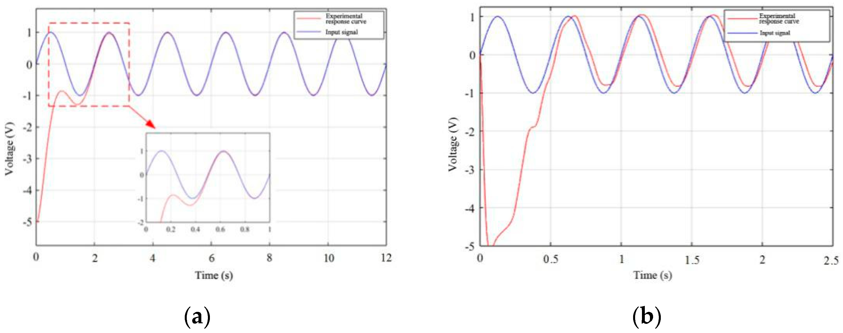
In order to further clarify the dynamic response performance of the system, take the sinusoidal signal as the system response, respectively, to verify the system 0.5 Hz, and 2 Hz sinusoidal excitation as the signal, when the system uses a low-frequency 0.5 Hz sinusoidal signal, as shown in Figure 16a, which has a better dynamic performance, in the process when the system extends and retracts, the system has a better dynamic characteristics and a smaller error and has a better robust performance. As shown in Figure 16b, when the 2 Hz sinusoidal signal is input, the dynamic performance of the system is significantly reduced, with obvious phase lag and error phenomenon, and when the piston of the hydraulic system extends, the process of the positional accuracy is poor, and there is a large error phenomenon. While the retraction process of the system piston extends the process, although there is a phase lag phenomenon, the position accuracy of the system is higher.
In summary, in order to ensure the dynamic performance of the hydraulic system in the process of digging holes, the linear state feedback controller based on LQR with feedforward is designed to improve the smooth performance of the system operation, and the position, velocity, and acceleration weights are considered, respectively, to regulate the state feedback gain of the system, which is a streamlined and economical control strategy without a complex solution and can meet the working engineering of the digging equipment. The simulation and experimental results show that there is a difference between the simulation and experiment, but the error is less than 10%, indicating that the control strategy is scientific and reasonable. During the experiment, there is a steady-state error in the displacement of the system during the stretching out process, and the error is 7.3%, while the system vibrates during the retraction process, and the vibration error is in the range of [−0.05 V, +0.05 V], which meets the requirement of a “double ten index”.

4. Conclusions

In this paper, a set intelligent planting control system based on a large seedling tree-planting machine is designed for the problems of high labor intensity, low efficiency, poor consistency of planting spacing, and planting depth of traditional manual tree planting methods. Through the study of the dynamic accuracy of the digging cylinder, an effective control strategy is proposed, which significantly improves the dynamic performance and planting quality of the tree planting machine.
In order to satisfy the fast response of the system and reach the ideal steady-state time, the dynamic performance of the cylinder in the process of digging holes is solved, and the planting quality is improved. In this paper, the relationship between the displacement trajectory of the rotating cutter disk and the displacement of the floating cylinder and digging cylinder is revealed by establishing the motion trajectory model of the intermittent digging mechanism. On this basis, the mathematical model of the electro-hydraulic servo system was established, and the operational performance of the hydraulic system under different excitation signals was simulated and analyzed using the Simulink simulation model. The test results show that the hydraulic piston rod displacement can demonstrate a linear outstretching trend in the range of 0~0.4 m, and the outstretching distance of the digging cylinder is 0~0.35 m, which ensures the linear change in this stroke. When the system extends the command to 1 V, the actual output is 0.6 m, and the relative error with the simulation value is less than 10%, which verifies the effectiveness of the control strategy. In addition, when 50~58.6 s when the hydraulic system is a steady state and outstretched, and the relative error with the simulation value is 7.3%, it meets the requirements of the “double ten index”.
The research of this paper provides new ideas and methods for the development of an intelligent tree planting machine, which is of great theoretical and practical significance for promoting the development of forestry mechanization and automation and realizing efficient and accurate automatic tree planting.

Author Contributions

Conceptualization and methodology, J.L., C.Y. and L.Y.; writing—original draft preparation, B.Z., H.Y. and Z.W.; software, H.Z.; formal analysis, H.Z. and B.Z.; writing—review and editing, B.Z., J.L. and L.Y. All authors have read and agreed to the published version of the manuscript.

Funding

This research was funded by the national key research and development project “Research and development of key technical equipment for light and simple cultivation of Camellia oleifera” (No. 2022YFD2202101).

Data Availability Statement

Data are contained within the article.

Conflicts of Interest

The authors declare no conflicts of interest.

References

  1. Ersson, B.T.; Laine, T.; Saksa, T. Mechanized tree planting in Sweden and Finland: Current state and key factors for future growth. Forests 2018, 9, 370. [Google Scholar] [CrossRef]
  2. Freedman, B.; Keith, T. Planting trees for carbon credits: A discussion of context, issues, feasibility, and environmental benefits. Environ. Rev. 2011, 4, 100–111. [Google Scholar] [CrossRef]
  3. Živković, M.; Urošević, M.; Komnenić, V. Technological and technical aspects of mechanized fruit tree planting. Poljopr. Teh. 2008, 33, 33–39. [Google Scholar]
  4. Zhu, B.; Yu, H.; Li, C. Design and Analysis of Intermittent Hole Digging Transplanter. For. Eng. 2020, 36, 39–44. [Google Scholar]
  5. Rantala, J.; Harstela, P.; Saarinen, V.-M.; Tervo, L. A Techno-Economic Evaluation of Bracker and M-Planter Tree Planting Device. Silva Fenn. 2009, 43, 659–667. [Google Scholar] [CrossRef]
  6. Zhang, P.; Wu, Z.; Yin, L. Research on Tree Planting Robots Based on Intelligent Control. Sci. Technol. Commun. 2017, 9, 42–43. [Google Scholar]
  7. Xu, C.; Lv, Z.; Xin, L.; Zhao, Y. Optimization Design and Experiment of Fully Automatic Strawberry Bowl Seedling Transplanting Mechanism. J. Agric. Mach. 2019, 50, 97–106. [Google Scholar]
  8. Liepins, K.; Lazdina, D.; Lazdins, A. Productivity and Cost-effectiveness of the M-Planter Tree Planting Machine in Latvian Conditions. Balt. For. 2011, 17, 308–311. [Google Scholar]
  9. Ma, L.; Wang, J.; Zong, W.; Huang, X.; Feng, J. Design and experiment of automatic feed mechanism with half nuts structure of portable digging machine. Trans. Chin. Soc. Agric. Eng. 2017, 33, 25–31. [Google Scholar]
  10. Jiang, C.; Yu, G. Development and experiment of efficient deep planting earth auger. Trans. Chin. Soc. Agric. Eng. 2013, 29, 75–83. [Google Scholar]
  11. Tang, Q.; Wu, J.; Jiang, L.; Wu, C.; Xiao, T.; Jiang, T. Design and experiment of hydraulic profiling system for rapeseed tillage and transplanting joint operation machine. J. Agric. Mach. 2021, 52, 95–102. [Google Scholar]
  12. Tang, Q.; Wu, C.; Wu, J.; Qin, C.; Jiang, L.; Wang, G. Research on the Electro hydraulic Proportional Control System for the Hole Distance of Rapeseed Rotary Tillage and Transplanting Joint Operation Machine. J. Agric. Mach. 2020, 51, 228–235. [Google Scholar]
  13. Fu, W.; Luo, X.; Zeng, S.; Wang, Z.; Wang, C.; Yuan, Q. Design and experiment of electro-hydraulic proportional control system for precise dry hole sowing machine for rice. J. Agric. Eng. 2015, 31, 25–31. [Google Scholar]
  14. Burce, M.E.; Kataoka, T.; Okamoto, H. Development of Seeding Depth Control System for Conservation Tillage Cultivation. J. Soc. Agric. Food Work. 2014, 76, 62–69. [Google Scholar]
  15. Yin, R.; Yuan, J.; Liu, X. Design and Test of Electro-Hydraulic Control System for Intelligent Fruit Tree Planter. In Advanced Manufacturing and Automation IX 9th; Springer: Singapore, 2020. [Google Scholar]
  16. Jin, K.; Song, J.; Li, Y.; Zhang, Z.; Zhou, H.; Chang, X. Linear active disturbance rejection control for the electro-hydraulic position servo system. Sci. Prog. 2021, 104, 15–23. [Google Scholar] [CrossRef]
  17. Li, J.; Li, W.; Du, X. Research on the characteristics of electro-hydraulic position servo system of RBF neural network under fuzzy rules. Sci. Rep. 2024, 14, 15332. [Google Scholar] [CrossRef]
  18. Sa, Y.; Zhu, Z.; Tang, Y.; Li, X.; Shen, G. Adaptive dynamic surface control using nonlinear disturbance observers for position tracking of electro-hydraulic servo systems. Proc. Inst. Mech. Eng. Part I J. Syst. Control Eng. 2022, 236, 634–653. [Google Scholar] [CrossRef]
  19. Nguyen, M.; Dao, H.; Ahn, K. Active disturbance rejection control for position tracking of electro-hydraulic servo systems under modeling uncertainty and external load. Actuators 2021, 10, 20. [Google Scholar] [CrossRef]
  20. Nguyen, M.; Dao, H.; Ahn, K. Adaptive robust position control of electro-hydraulic servo systems with large uncertainties and disturbances. Appl. Sci. 2022, 12, 794. [Google Scholar] [CrossRef]
  21. Naveen, C.; Meenakshipriya, B.; Tony, T.A.; Sathiyavathi, S.; Sathishbabu, S. Real-time implementation of iterative learning control for an electro-hydraulic servo system. IETE J. Res. 2023, 69, 649–664. [Google Scholar] [CrossRef]
  22. Zhang, D.; Liu, S.; Chen, Y.; Gu, C.C. Neural direct adaptive active disturbance rejection controller for electro-hydraulic servo system. Int. J. Control Autom. Syst. 2022, 20, 2402–2412. [Google Scholar] [CrossRef]
  23. Sun, C.; Dong, X.; Wang, M.; Li, J. Sliding mode control of electro-hydraulic position servo system based on adaptive reaching law. Appl. Sci. 2022, 12, 6897. [Google Scholar] [CrossRef]
  24. He, J.; Su, S.; Wang, H.; Chen, F.; Yin, B. Online PID Tuning Strategy for Hydraulic Servo Control Systems via SAC-Based Deep Reinforcement Learning. Machines 2023, 11, 593. [Google Scholar] [CrossRef]
  25. Wu, Z. Hydraulic Control System; Higher Education Press: Beijing, China, 2008; pp. 106–201. [Google Scholar]
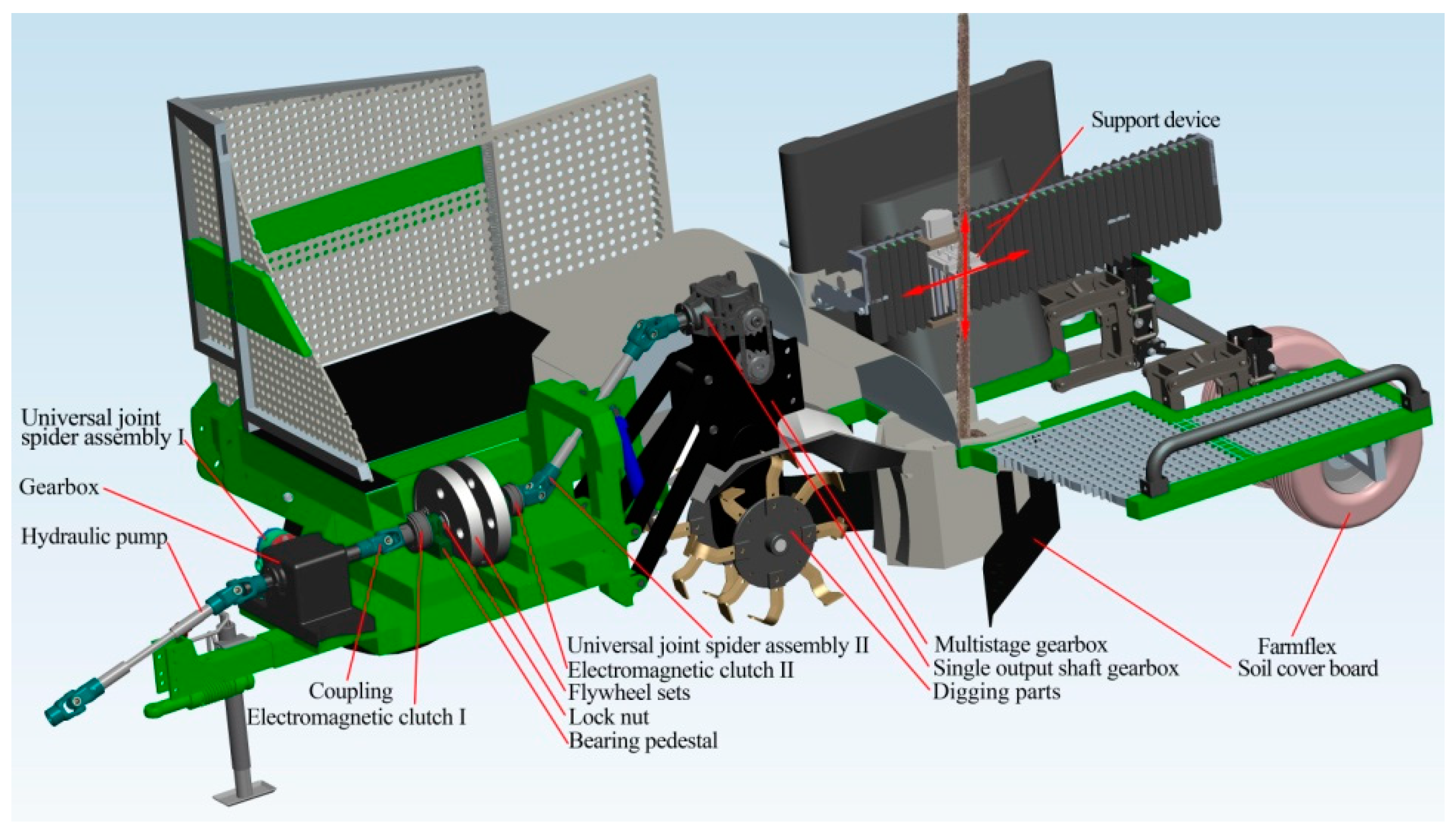
Figure 1. Three-dimensional modeling of a tree planting machine.
Forests 15 01744 g001
Figure 2. Simplified planar linkage mechanism.
Forests 15 01744 g002
Figure 3. Working principle of the hydraulic actuator for digging holes.
Forests 15 01744 g003
Figure 4. Values of Cr, Crc, Cs, and Csc time domain curves.
Forests 15 01744 g004
Figure 5. (a). Cr, Crc step response curves; (b). Cs, Csc step response curves. Time domain curves of the system are analyzed for the conditions of Cr, Crc, Cs, and Csc.
Forests 15 01744 g005
Figure 6. Simplified Simulink simulation model of the system.
Forests 15 01744 g006
Figure 7. Simulink simulation model of asymmetric hydraulic system.
Forests 15 01744 g007
Figure 8. (a). Step response curve; (b). Sine response curve. Time domain curves of the step and sinusoidal response.
Forests 15 01744 g008
Figure 9. (a). Simulink simulation model; (b). LQR code program. Simulation model of hydraulic system based on LQR linear state feedback control with feedforward.
Forests 15 01744 g009
Figure 10. Step response of piston rod extension system.
Forests 15 01744 g010
Figure 11. Step response of piston rod retraction system.
Forests 15 01744 g011
Figure 12. (a). The 0.1 Hz sinusoidal signal response curve; (b). 0.5 Hz sinusoidal signal response curve; (c). 1 Hz sinusoidal signal response curve; (d). 2 Hz sinusoidal signal response curve. Sine response curve of the system.
Forests 15 01744 g012aForests 15 01744 g012b
Figure 13. Composition structure of the electro-hydraulic position servo system.
Forests 15 01744 g013
Figure 14. Upper computer experiment model.
Forests 15 01744 g014
Figure 15. (a). Response curve of the hydraulic system during extension; (b). response curve of the hydraulic system during retraction. Step response curve.
Forests 15 01744 g015aForests 15 01744 g015b
Figure 16. (a). The 0.5 Hz sinusoidal response curve; (b). 2 Hz sinusoidal response curve. Sinusoidal response curve.
Forests 15 01744 g016
Table 1. Hydraulic cylinder system parameters.
ParameterValueParameterValue
Piston rodless chamber area A1 (m2)1 × 10⁻³Piston rodless cavity area A2 (m2)0.5 × 10⁻³
Initial volume of hydraulic cylinder Vt (m3)2 × 10⁻⁴Viscous friction of hydraulic system Bp (N/(m/s))500
Effective volume modulus of elasticity of hydraulic fluid βe (Pa)7 × 10⁸Electro-hydraulic proportional valve flow gain Kqr1.53
Electro-hydraulic proportional valve flow gain Kqs2.35Rated supply pressure Ps (MPa)21
Load mass m (kg)30Hydraulic oil density ρ (kg/m3)850
Total hydraulic cylinder flow-pressure coefficient Kcs (m3/s·Pa)4.6 × 10−9Total hydraulic cylinder flow-pressure coefficient Kcr (m3/s·Pa)6.7 × 10−9
Electro-hydraulic proportional valve gain Kv (mm/V)5 × 10−4Displacement sensor feedback gain Kx (V/m)5
Disclaimer/Publisher’s Note: The statements, opinions and data contained in all publications are solely those of the individual author(s) and contributor(s) and not of MDPI and/or the editor(s). MDPI and/or the editor(s) disclaim responsibility for any injury to people or property resulting from any ideas, methods, instructions or products referred to in the content.