Article

Influence of Salt Concentration and Treatment Cycles on Nail-Holding Power in Dimension Lumber

1
College of Materials Science and Engineering, Nanjing Forestry University, Nanjing 210037, China
2
Fujian Provincial Institute of Architectural Design and Research Co., Ltd., Fuzhou 350001, China
*
Author to whom correspondence should be addressed.
Forests 2024, 15(8), 1387; https://doi.org/10.3390/f15081387
Submission received: 28 June 2024 / Revised: 3 August 2024 / Accepted: 6 August 2024 / Published: 8 August 2024

Abstract

:
To rigorously analyze the effects of high-salt environments on dimension lumber and provide scientific and reliable data to facilitate the advancement of light-frame construction in such environments, this study subjected dimension lumber to salt solution treatment. The study investigated the trend of nail-holding power variations across the radial, tangential, and cross-sections of spruce–pine–fir (SPF) dimension lumber under varying salt concentrations and treatment durations. The experimental results exhibited a significant influence of salt on the nail-holding power across all sections of the SPF dimension lumber. As the concentration of salt solution increased, the holding power gradually decreased across all directions, exhibiting considerable differences across salinity gradients. Specifically, the radial and tangential sections exhibited a 15%–20% higher nail-holding power compared to the cross-section. An increase in the salt solution concentration above 3% corresponded to an approximate 1% decrement in nail-holding power per section for every 0.5% rise in concentration. Additionally, prolonged salt treatment initially resulted in an increase, followed by a subsequent decrease in nail-holding power, demonstrating a consistent pattern across all variations. Post hoc analyses confirmed that the differences between individual salt concentrations, including between 3.5%, 4%, and 4.5%, were statistically significant. These findings provide valuable data for understanding the degradation of timber connectors in high-salt environments, contributing to the development of more durable and resilient wood-frame buildings in such conditions.

1. Introduction

In the realm of wooden structural construction, the choice of connection methodology holds paramount importance. Nailed connections continue to be widely adopted due to their ease of fabrication and commendable performance in joints. However, a notable concern arises regarding the susceptibility of these metal connections to corrosion over prolonged usage, which significantly reduces joint strength. Wood structures in high-salt environments are prone to accelerated deterioration, manifesting in forms such as decay, perforations, cracks, and various other types of damage, thereby compromising structural safety [1]. Slamová et al. [2] developed a map outlining the atmospheric corrosion in coastal regions, utilizing a geo-statistical approach and modeling methodology derived from ISO 9223. The primary atmospheric corrosion factors considered in their study included airborne salinity, humidity, and sulfur dioxide emission [2]. The research results showed that on the global map, it can be seen that in the coastal regions of China and Brazil, the east coast of USA, in the Central American states, on the Arabian Peninsula, and in Turkey, high atmospheric corrosion can be found [2]. Timber has been used for centuries in marine structures such as revetments, jetties, breakwaters, and lock gates. These structures are subjected to a harsh environment, especially in the tidal zone where they are periodically exposed to high salinity such as seawater [3,4,5].
In light wood-frame structures, the connections between the floor/ceiling panels and the wall studs experience upward pull-out forces under horizontal loads such as earthquakes, where the nail-holding power plays a dominant role. Additionally, in resisting horizontal loads, the nail connections between the construction sheathing and the wall studs significantly contribute to the nail-holding power, with the magnitude of the nail-holding power directly affecting the nail’s withdrawal resistance [6]. Therefore, this study primarily focuses on nail-holding power as a key strength metric, reflecting the performance of timber joints.
Despite extensive research on various aspects of timber connectors, there is limited information on the specific influence of high-salt environments on these connections. Most scholars have focused on the wet and dry cycles rather than the high-salt environments. Fei et al. [7] ascertained that wood density plays a pivotal role in determining the nail-holding power, where a direct proportionality is observed between nail diameter and nail-holding capacity. Further studies by Wang et al. [8] explored the impact of repeated drying and wetting cycles on the withdrawal capability of wooden and metal nails. Their results indicated that wooden nails undergo a more rapid degradation in performance following exposure to dry and wet cycles, whereas galvanized ring nails exhibit minimal quality loss, thereby emphasizing the significance of employing galvanized fasteners in damp environments.
Teng et al. [9] conducted rigorous dimensional lumber tests, revealing that alterations in the nailing angle along the wood grain can lead to substantial variations in the retention capacity of both round steel nails and self-tapping screws. The study also highlighted that the density of different wood species directly impacts their holding power, while the choice of nail type significantly affects the degree of displacement under maximum pull-out load.
In a separate study, Zelinka et al. [10] conducted a comprehensive analysis of the corrosion rate of metal fasteners in treated wood, delving into the underlying corrosion mechanisms. They determined the corrosion rate through the mass residual rate and analyzed corrosion products using scanning electron microscopy, X-ray energy spectroscopy, and X-ray diffraction. In another study, Yermán et al. [11] evaluated the performance of plain and electro-galvanized fasteners on untreated and organic solvent-treated pine, subjecting them to eight wet and dry cycles. Their findings suggest that chemical corrosion can significantly influence nail-holding strength, with electro-galvanized fasteners exhibiting superior corrosion resistance.
Salt solution, a prevalent environmental factor, not only induces discoloration and aging in wood but also expedites the rusting and deformation of metal connectors within wood structures. This, subsequently, has a direct and significant effect on the load-bearing capabilities of connections, thereby diminishing the overall reliability and safety of wood structure buildings [12]. It is of the utmost importance to investigate the influence of high-salt environments on the performance of joints in wood structures. The current study endeavors to scrutinize the trend of variation in nail-holding power across the radial, tangential, and cross-sections of spruce–pine–fir (SPF) dimensional lumber, under varying salt concentrations and treatment durations. By assessing the impact of salt concentration on the degradation of nail-holding power over time, our goal is to formulate a linear model that accurately predicts the nail-holding power in high-salt environments. This research will bridge these gaps by providing detailed data on the influence of high-salt environments on timber connectors, contributing to the field of wooden structural construction in challenging environmental conditions.

2. Materials and Methods
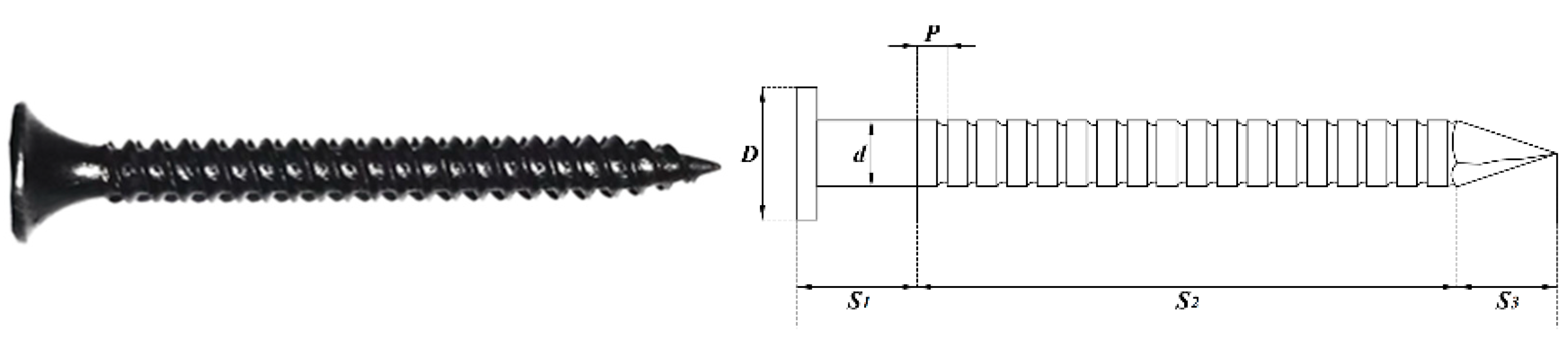
2.1. Nails

The nails employed in the construction of wooden structures encompass a variety of types, including steel nails, screws, U-nails, and others. Recently, there has been a surge in the popularity of wooden nails. Based on practical production considerations, we have chosen to utilize spiral nails, which are widely utilized in the construction of wooden structures [13]. The spiral nails used in this study are made of galvanized steel, providing enhanced corrosion resistance that is suitable for high-salt environments. The bending yield strength of these nails is 621 ± 26 MPa, which ensures adequate holding power and durability. The precise specifications of these nails are detailed in Table 1 and further illustrated in Figure 1.

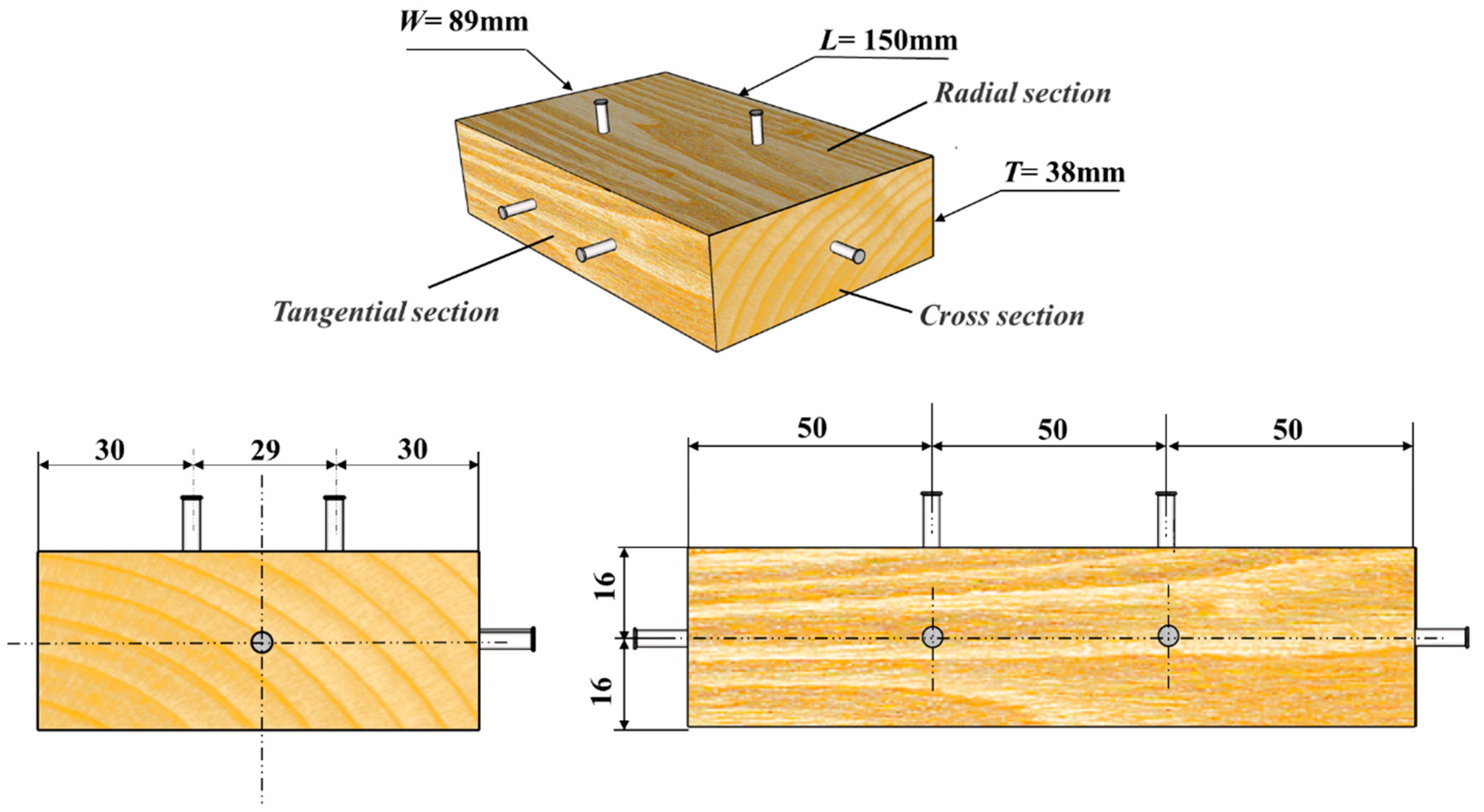
2.2. Dimension Lumber

SPF is widely used in light frame construction, ensuring the practical relevance of the study results, the physical and mechanical properties of SPF wood are suitable for experimental conditions and can simulate real-world environments well. So, it was chosen as the material for fabricating the specimens, with the main tree species being spruce. Five wet–dry cycles were conducted, and for each cycle, five samples were selected from each group for the tests. The study comprised 160 samples of SPF lumber, each measuring 150 mm in length, 89 mm in width, and 38 mm in thickness. The initial moisture content of the specimens was determined using oven drying at 103 °C. The average moisture content was recorded at 13.2% ± 1% [14], while the average density was measured to be 480 ± 20 kg/cm3 [15]. According to GB/T 1927–2022, the depth of penetration of the nail, excluding the sharpened tip, should be two-thirds of the nail length, including the sharpened tip. Therefore, before testing, the nails were carefully cleaned and marked at a distance of 12 mm from their tips [16]. Two nails were hand-hammered 5–10 times into the specimen at right angles to the surface in the radial, tangential, and grain directions according to the layout shown in Figure 2. The nails were inserted into the specimens at a consistent speed, perpendicular to the surface, in the radial, tangential, and cross-sectional planes until the marked position was reached. The depth of penetration of the nails were measured to an accuracy of ±1 mm [17]. The experiment lasted for a total of 30 days, with each cycle representing a 5-day period consisting of 3 days of soaking and 2 days of drying. The methodology for the soaking and drying durations was based on the previous literature [18], ensuring an adequate simulation of real-world wet–dry conditions. Refer to Table 2 for specific experimental steps.

2.3. Salt Solution Treatment

A rigorous experimental protocol was conducted utilizing a simulated high-salinity solution. This solution was meticulously prepared using biochemical sea crystals and featured various concentration gradients (mass fraction), specifically 0%, 3%, 3.5%, 4%, and 4.5%. These specific salt concentration levels were chosen to represent a realistic range of salinity levels found in coastal and high-salt environments, ensuring the study’s applicability to real-world conditions [18]. Furthermore, a control group was established using distilled water, and the specific preparation composition can be referenced in Table 3. During the soaking procedure, the specimens were completely submerged in the simulated solution, ensuring thorough permeation without contacting any container walls, as illustrated in Figure 3. The aim was to replicate the long-term exposure and recovery process of materials under practical conditions as accurately as possible. To minimize water evaporation during the experiment, a layer of plastic wrap was placed over the container. Additionally, the salt solution was replaced every two months and recalibrated to maintain precise salt concentration levels. To systematically evaluate the impact of salinity on lumber performance, particularly nail-holding capacity, a soaking duration of three days followed by a drying period of two days was established for each experimental cycle. This cycle aimed to simulate the periodic wetting and drying conditions that wooden structures typically experience in coastal environments. Figure 3 depicts some specimens tested across various cycles and concentrations. By incorporating these specific salt concentration levels and experimental conditions, the study seeks to provide comprehensive insights into the effects of high-salt environments on the structural integrity and performance of wooden connections.

2.4. Equipment

The testing apparatus utilized was the Suns Universal Mechanical Testing machine, capable of handling loads up to 100 KN. In accordance with the GB/T 1927.21-2022 standard [16], the test specimen was precisely positioned within the nail-holding fixture, with the nail head gripped at a controlled speed of 2 mm per minute [17]. Subsequently, the nail was extracted within a time frame of 1–2 min. The peak load was recorded with a precision of 10 N (refer to Figure 4). Subsequently, the nail-holding capacity was computed using Equation (1).
P = P m a x L
where
P is the nail-holding power of the sample (N∙mm−1);
Pmax is the maximum load (N);
L represents the depth that nails into the specimen (mm).

3. Results and Discussions

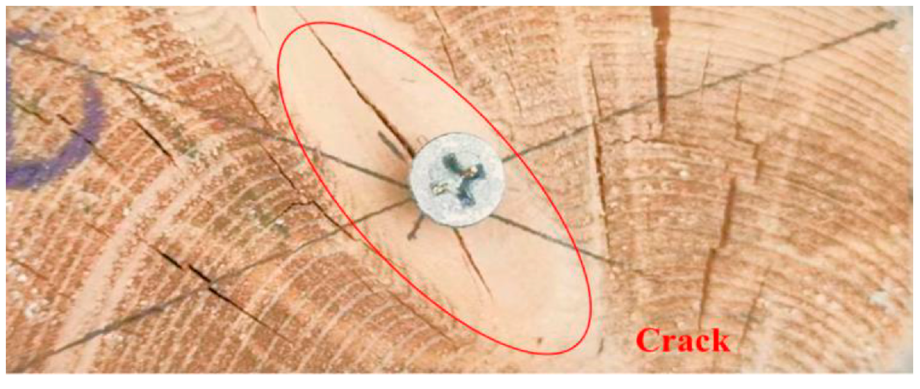
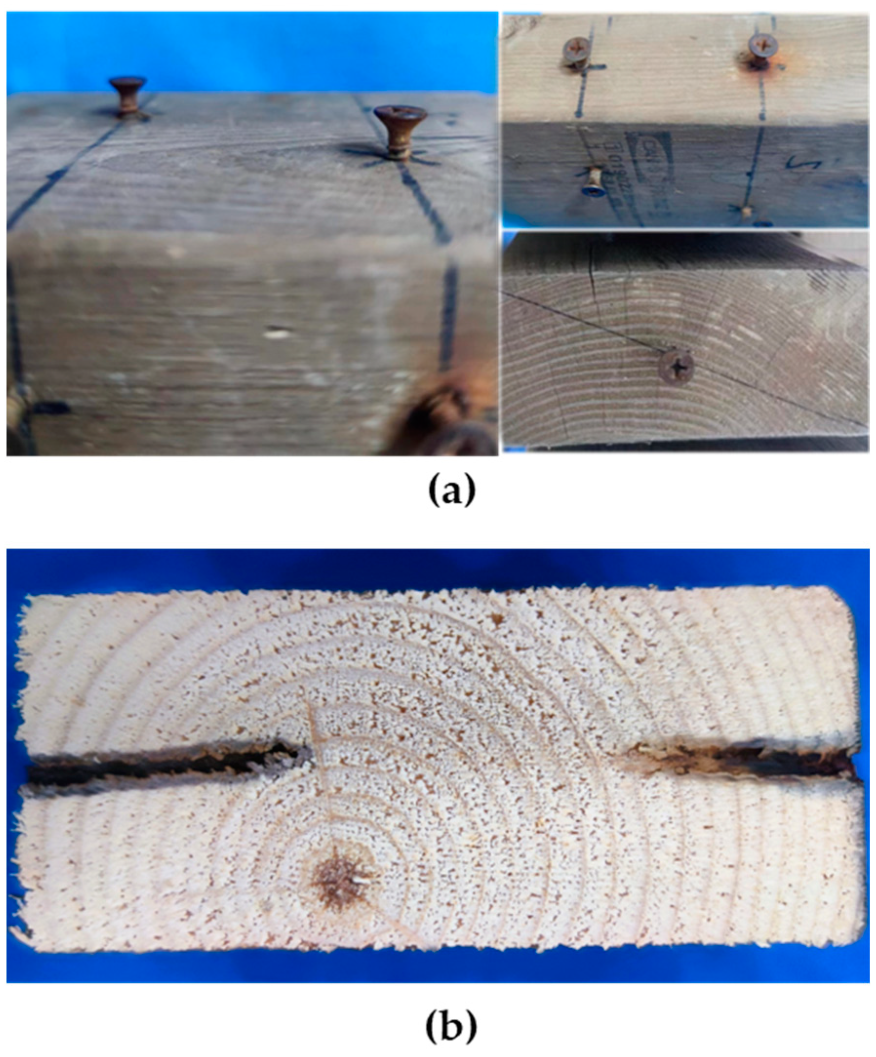
3.1. Visual Characterization of Wood Samples

Following cyclic treatment, numerous wood samples exhibited the development of cracks, including those extending through the fasteners. Figure 5 illustrates this occurrence. A marked increase in cracking propensity was observed with an elevation in the number of cycles, particularly among samples treated with highly concentrated salt solutions (≥3.5%). By the fourth cycle, over 40% of the samples displayed cracks.
Conversely, in instances involving high salt concentration and numerous treatment cycles, excessive corrosion of the nails was observed, occasionally leading to the embedding of rust particles into the contact surface between the wood and the nails. Rust particles visible on the contact surface between the wood and the nails indicated the corrosion process. Cracking and splitting of the wood around the nails would occur due to stress and moisture fluctuations. The internal cross-section of the wood showing the extent of rust penetration and the impact on the wood’s integrity are depicted in Figure 6.
During the experiment, it was noted that the grooves of the spiral nails were encased with small wood fibers. These fibers exhibited significantly larger dimensions in the radial direction compared to the tangential direction. The threads and chips displayed an almost perfect fit. This phenomenon can be attributed to the gradual relaxation and fracture of the wedge-shaped wood within the threads during the pull-out process. This leads to a gradual reduction in the force between the nail and the wood fibers, resulting in a decrease in the nail-holding power over time.

3.2. Load-Displacement Characteristics

The curve of distilled water treatment (control group) exhibited a distinct linear pattern during the initial stages. Upon reaching the peak load, they underwent a rapid linear decline, followed by a nearly linear and consistent decrease. This behavior is evident in Figure 7. Friction plays a significant role in determining the nail’s holding power. Although the untreated and treated samples exhibited similar trends in their load-displacement curves, the treated samples showed a slower initial increase in load and a faster decrease towards the end. This behavior can be explained by the increased adhesion between the wood fibers and nails in the treated specimens. Over time, corrosion products form due to prolonged exposure to saltwater, creating a bond between the wood fibers and the nails. When the failure occurs within this adhesive layer, it accelerates the rate at which the pullout load decreases, leading to a more rapid loss of holding power in the treated samples. Conversely, the untreated curves exhibited an abrupt decrease in load after reaching the peak, followed by a nearly linear and consistent decline due to the absence of adhesion. These observations align with the findings from similar studies that have documented the impact of corrosion on the mechanical properties of wood–metal connections. The presence of corrosion products has been shown to alter the failure mechanisms of the joints, as described by Skulteti et al. [6], where the degradation of the wood surrounding the fasteners due to prolonged exposure to corrosive environments significantly impacted the joint performance.

3.3. The Nail-Holding Power

Table 4 presents the nail-holding power for the three sections derived after cyclic treatment with varying concentrations and cycles. PS1 in the table represents the radial section of the nail-holding power. PS2 stands for tangential section. PS3 stands for cross section.

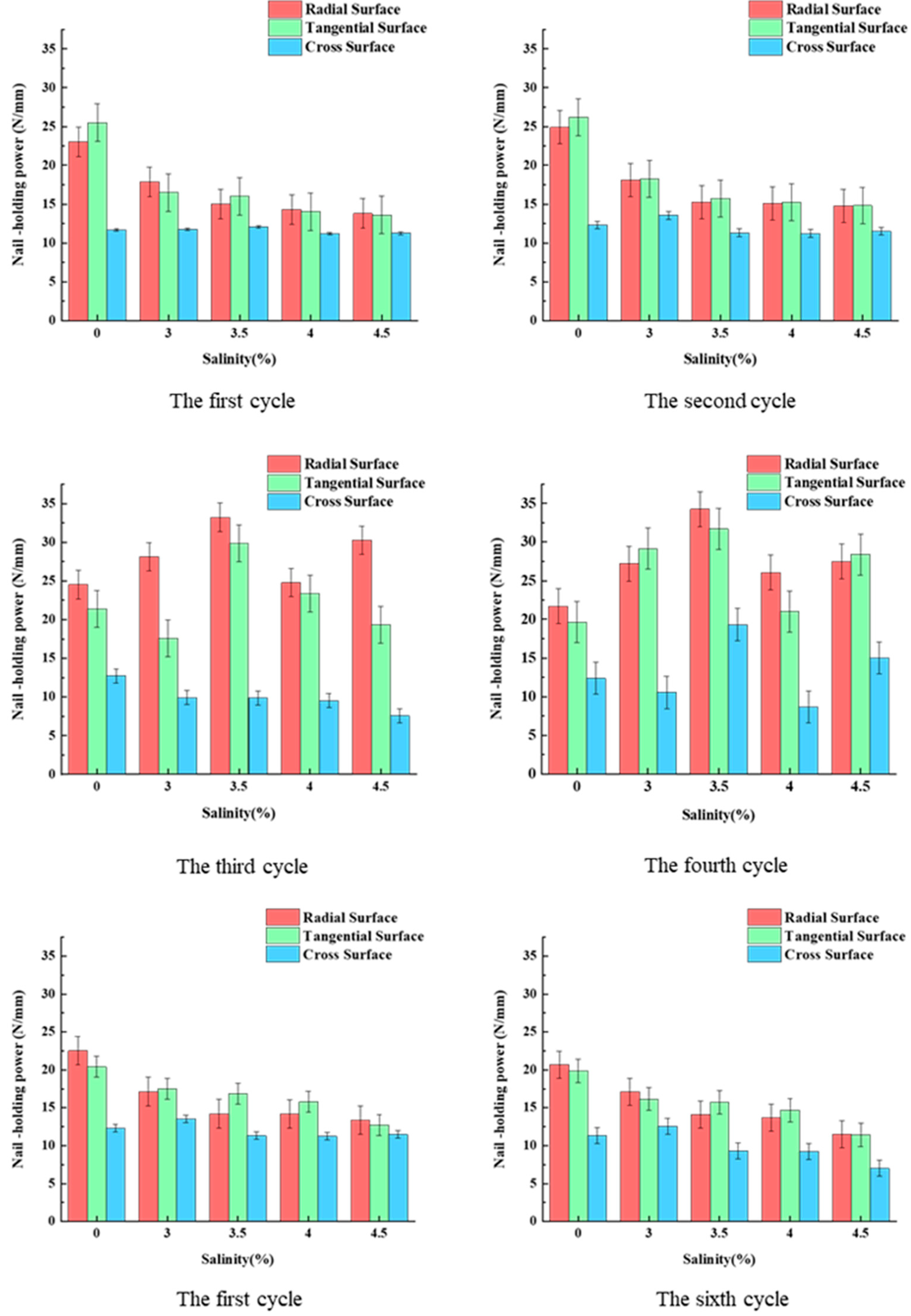
3.4. Differences in Nail-Holding Power across Three Sections

In coastal environments, various structures are critically dependent on the nail-holding power of their wooden components. In residential buildings, the connections between floor/ceiling panels and wall studs experience significant upward pull-out forces under horizontal loads such as wind or seismic activity, making robust nail-holding power essential for maintaining structural integrity and safety. Boardwalks and coastal pathways, often constructed with wooden planks fastened by nails or screws, face constant exposure to salt air and occasional direct contact with seawater, which can weaken fasteners over time [5]. Understanding and mitigating the effects of salt on nail-holding power is crucial for user safety. Similarly, beachfront infrastructure—including lifeguard towers, beach huts, and coastal observation decks—is directly impacted by salt fogs and seawater [10,11]. Ensuring strong nail-holding power in these structures is vital to withstanding harsh coastal conditions and ensuring their longevity and safety.
Some studies have shown that the radial and tangential sections exhibit higher holding power compared to cross-sections, which is consistent with our findings [19]. As shown in Figure 8, under identical salt treatment concentrations, the nail-holding power in the cross-section is significantly lower compared to that of the radial and tangential areas, representing only 23.4% of the latter two. Moreover, the fluctuation range in the holding power of the cross-sectional nails is considerably smaller than that of the radial and tangential holding powers. This discrepancy arises from the fact that the drying shrinkage in the tangential direction of the wood is much greater than in the radial and longitudinal directions. Consequently, the cross-section of the wood is more susceptible to cracking during natural drying, resulting in reduced friction between the wood and the nail and consequently, a smaller nail-holding power. With the prolongation of the treatment period, the cross-sectional holding power decreased by approximately 15.7%, and the cross-sectional holding power decreased by approximately 10.8% as well. Taking the 3.5% salt solution as an example, the third cycle exhibited a slight increase, whereas the fourth cycle demonstrated a notable decrease. It is noteworthy that the cross-sectional nail-holding power did not decline as rapidly as the radial and tangential holding powers. This phenomenon can be attributed to the repeated wet-and-dry treatment, which leads to dry shrinkage and wet swelling of the wood. This, in turn, increases the spacing between the wood fibers and the nail, resulting in a significant decrease in nail-holding power during the initial stages. Structural durability is crucial in determining the reliability of buildings [20]. The influence of salt on the withdrawal performance of wooden structures is significantly affected by the length of time that the wood members are exposed to saline environments [19]. As a result, the nail withdrawal capacity of the wooden structures can vary under differing treatment cycles in salt-rich conditions.
Additionally, chemical reactions are also the main factor affecting the change in nail-holding power. A galvanic reaction occurred in the galvanized spiral nails immersed in the NaCl solution, as depicted in Figure 9. The cathodic reaction was Zn-2e = Zn2+, and the anodic reaction was O2 + 2H2O + 4e = 4OH. Zinc gradually loses electrons and dissolves through oxidation, forming a dense and well-insulated corrosion product film of ZnCl2 and Zn(OH)2 that serves as a protective barrier. This film enhances friction between the wood fibers and the nail, leading to a slight increase during the fourth cycle [21]. However, as the reaction progresses, the galvanized layer gradually dissolves, and the internal iron atoms begin to corrode in the complex, high-salt solution environment. Furthermore, as corrosion products accumulate [22], excessive radial adhesion of the nail occurs, resulting in a decrease in nail-holding power. Rust formation was also observed on the outer diameter of the nail during the fifth cycle of the experiment, indicating the complete dissolution of the galvanized protective layer [23]. In conclusion, the corrosion of galvanized spiral nails in salt water involves the continuous accumulation and shedding of loose corrosion products.

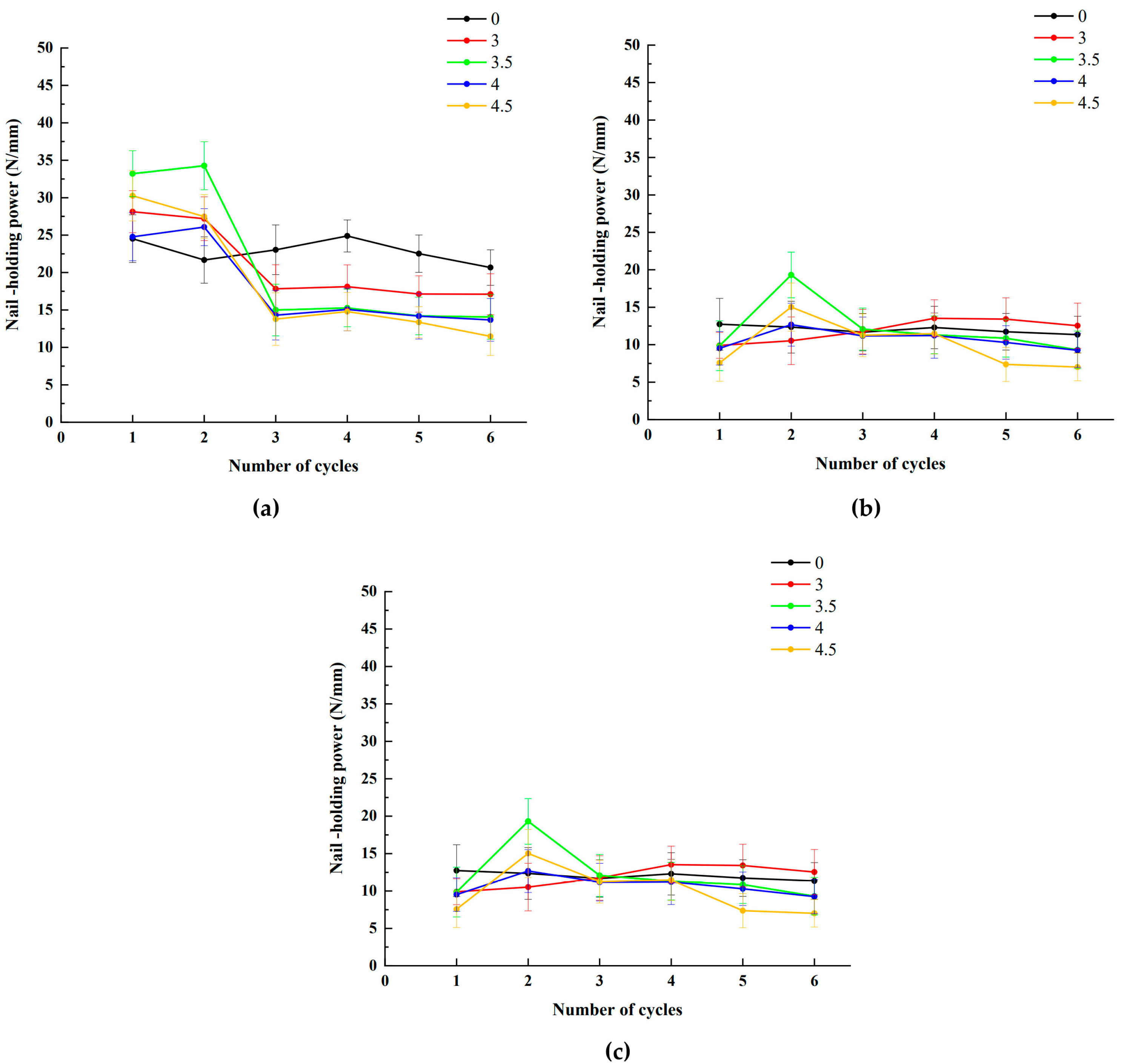
3.5. Effect of Salinity and Treatment Cycle on Nail-Holding Power

The variation in the specimen’s nail-holding power under different concentrations of salt environmental treatment depends on the concentration of the salt solution and the extent of hydrolysis. These results are illustrated in Figure 10.
The data presented in Figure 10 reveal a general trend of lower nail-holding power in saline environments compared to those in clean water. Furthermore, there is a gradual decrease in holding power with increasing salinity. For instance, during the fourth week, at a salt concentration of 3%, the nail-holding power values were 18.11 N∙mm−1, 18.25 N∙mm−1, and 13.53 N∙mm−1, respectively. However, upon increasing the concentration to 4.5%, the respective values decreased to 14.78 N∙mm−1, 14.80 N∙mm−1, and 11.48 N∙mm−1, indicating a decline of 15.2%, 18.4%, and 18.9% in nail-holding power on each side. Notably, when the salt concentration ranged between 3% and 3.5%, the nail-holding power decreased significantly by approximately 15%. Subsequently, with each 0.5% increase in salt solution concentration above 3.5%, the nail-holding power decreased gradually by approximately 1% on each side. Additionally, as the duration of salt treatment increased, the nail-holding power exhibited a consistent pattern across different salt concentrations, with consistently lower values in saline environments compared to regular water and a gradual decrease with increasing salinity, albeit at a gradual rate.
These observations are consistent with previous studies, which found that wood exposed to high salt concentrations exhibited significant hydrolytic degradation, resulting in reduced mechanical properties and lower nail-holding power [24], particularly the concentration of the solution and the degree of hydrolysis [25,26]. These two factors contribute significantly to the decline in nail-holding power. When wood is repeatedly exposed to sunlight, a dissolution reaction ensues between NaCl and water vapor present in the atmosphere. This reaction involves the dissolution of sodium chloride in water, yielding hydroxide ions (OH) and chloride ions (Cl). Subsequently, these hydroxide ions react with carbon dioxide present in the air to form carbonate ions (CO32−). In the final stage, carbonate ions combine with hydrogen ions (H+) to produce water and hydrochloric acid (HCl). The overall chemical reaction can be summarized as NaCl + H2O + CO2 → HCl + NaHCO3.
As a consequence of this chemical reaction, the ZnO protective layer coating the nail oxidizes to form ZnCl2, leading to the gradual dissolution of zinc. This dissolution process leads to a reduction in friction between the nail and wood fibers, resulting in a corresponding decrease in nail-holding power. Furthermore, higher concentrations of salt solution contain an increased number of chloride ions, amplifying the aforementioned reaction in accordance with Le Chatelier’s principle. Consequently, as salinity increases, nail-holding power decreases, and varying salt concentrations expedite metal corrosion to varying extents. However, due to the limited availability of water vapor in the test environment, the reaction remains incomplete, resulting in a gradual and subtle decline in nail-holding power.

3.6. Statistical Analysis

Table 5 shows the analysis of variance and significance test for the effect of salinity concentration and cycle period on nail-holding power. The ANOVA results reveal that both salinity and cycle significantly influence the nail-holding power across all three surface positions (PS1, PS2, PS3). Additionally, the interaction between salinity and cycle is significant, indicating that the effect of salinity on nail-holding power varies depending on the cycle. The large partial eta-squared values for the cycle and the interaction terms suggest that these factors explain a substantial proportion of the variance in nail-holding power.
Following the significant ANOVA results, the post hoc analysis using the Bonferroni correction revealed significant differences in the mean radial section nail-holding power (PS1) across various salinity levels and cycles (Table 6): The post hoc analysis of PS1 revealed several significant differences. At 0.0 salinity, the cycle pairs 2.0 vs. 4.0, 3.0 vs. 4.0, 3.0 vs. 6.0, 4.0 vs. 6.0, and 5.0 vs. 6.0 exhibited significant differences. Notably, the mean difference between 0.0 and 6.0 cycles was −6.104 (p = 0.010) and −6.150 (p = 0.009) for the 2.0 and 3.0 cycles, respectively. At 3.0 salinity, all cycle comparisons involving the 6.0 cycle displayed significant differences, with the largest being 19.706 (p < 0.0001). Additionally, salinities 3.5, 4.0, and 4.5 also showed significant differences across multiple cycle pairs, highlighting the substantial impact of cycle duration on nail-holding power under varying salinity conditions.
Due to space limitations, only the post hoc analysis of PS1 is listed in this Table.
Comparisons were made between the different salinity levels for the same cycle (Table 7). For Cycle 1.0, significant differences were observed between salinity levels 0.0 and 3.5, 0.0 and 4.0, and 0.0 and 4.5. For Cycle 2.0, significant differences were found between salinity levels 0.0 and 3.0, 0.0 and 3.5, and 0.0 and 4.5. Cycle 3.0 showed significant differences between salinity levels 0.0 and 3.5, and 0.0 and 4.5. Additionally, significant differences were found across various salinity levels in Cycles 4.0, 5.0, and 6.0, emphasizing the considerable impact of salinity on nail-holding power within different cycles.
Similarly, PS2 revealed significant differences in nail-holding power. Notably, Cycle 1.0 at 0.0 salinity significantly differed from 3.5 and 4.5 salinity. Significant differences were also found for Cycle 2.0 between 0.0 and 3.0, and 3.5, and 4.5 salinity, with 3.5 and 4.5 differing from 4.0. For Cycle 3.0, significant differences were observed between 0.0, 3.0, 3.5, and 4.0, and 4.5 salinity. Similarly, Cycle 4.0 showed significant differences with 0.0, 3.0, 3.5, 4.0, and 4.5 salinity, indicating the impact of varying salinity levels on nail-holding power across cycles.
Post hoc analysis for PS3 indicated significant differences in nail-holding power between several salinity levels and cycles. Specifically, Cycle 2.0 at 0.0 salinity significantly differed from 3.5, and differences were observed for Cycle 3.0 between 0.0 and 3.5, and 4.5 salinity. Cycle 3.5 showed significant differences with 4.0 salinity. For Cycle 4.0, significant differences were noted between 0.0 and 4.5, 3.0 and 4.5, 3.5 and 4.5, and 4.0 and 4.5 salinity. Lastly, Cycle 6.0 at 0.0 and 4.5 salinity also showed significant differences, highlighting the influence of salinity on nail-holding power.

3.7. Synthesize and Analyze

The regression curve and formula of each surface’s nail-holding power can be obtained from Figure 11 on the same cycle in different salinities.
The radial-sectional holding power model is as follows:
y = 2.204 x + 23.404
the tangential-sectional holding power is as follows:
y = 2.628 x + 23.404
the cross-sectional holding power is as follows:
y = 0.148 x + 12.002
where
x is the solution concentration (%),
y is the holding power (N∙mm−1).
The correlation coefficients of the radial-sectional and tangential-sectional nail-holding power were 0.91 and 0.86, respectively. The cross-sectional holding power is also within the reliable range of 0.63.
Different salt concentrations accelerate metal corrosion to varying degrees. Under certain temperature conditions, the corrosion rate is influenced by two main factors—salt concentration and the dissolved oxygen content in the solution [27]. At low concentrations, high oxygen solubility in the environment promotes unrestricted reactions, resulting in a high corrosion rate. Conversely, at high concentrations, reduced oxygen solubility impedes the electrochemical reaction, leading to a peak concentration where the reaction rate is constrained by both oxygen content and chloride ion concentration. Although extensive research has been conducted globally, the test results have demonstrated significant variations in corrosion across different regions due to diverse natural environments. Hence, there is considerable value in quantitatively analyzing corrosion in different environments [28]. The impact of the solution on wood is influenced by salt concentration and hydrolysis degree. Salt solutions at high temperatures and pressures partially dissociate wood, interacting with alkaline salts to decompose lignin with minimal effect on wood polysaccharides. Neutral salts hydrolyze polysaccharides at high temperatures without affecting lignin, while salt oxidation causes wood discoloration. Prolonged exposure to sunlight, ultraviolet light, and other forms of irradiation accelerates adhesive aging and reduces product performance over time.
Overall, it appears that changes in the load carrying capacity of metal connectors in high-salt environments primarily result from chemical interactions between the salt solution environment, wood, and galvanized nails [29]. The formation of chelates between the galvanized protective layer and tannins in the wood creates a film that reduces the physical adhesion between the zinc and the wood. This weakens the joints in the timber frame buildings, impacting overall stability and reliability. Additionally, chelate formation renders the zinc surface more vulnerable to environmental attack. Outdoor exposure to moisture, acidity, and other corrosive elements further accelerates zinc corrosion, increasing the risk of nail surface degradation, reducing service life, and challenging the durability of wood-framed structures. Interaction between zinc and tannins in wood may result in damage to the timber joint, potentially weakening or destabilizing them and compromising overall nail mechanical properties, including strength and durability.

4. Conclusions

Tests on the effect of the load bearing capacity of wood structural metal connectors in high-salt environments lead to the following conclusions:
(1)
The nail-holding power of SPF lumber is significantly influenced by salt concentration and treatment duration. Radial and tangential sections exhibit a 15%–20% higher holding power than the cross-section. Initially, nail-holding power increases by up to 10% after two cycles but then declines. Each 0.5% increase in salt concentration from a 3% baseline results in about a 1% decrease in holding power, demonstrating a clear correlation. Analysis of variance shows that salinity and cycle duration significantly affect nail-holding power across all positions, with substantial differences observed between various levels and cycles. The functional relationship of each side nail-holding power changing with the high-salt treatment cycle is as follows: The radial-sectional holding power model is y = −2.204x + 23.404 (R2 = 0.91), the tangential-sectional holding power model is y = −2.628x + 23.404 (R2 = 0.86), and the cross-sectional holding power model is y = −0.148x + 12.002 (R2 = 0.63).
(2)
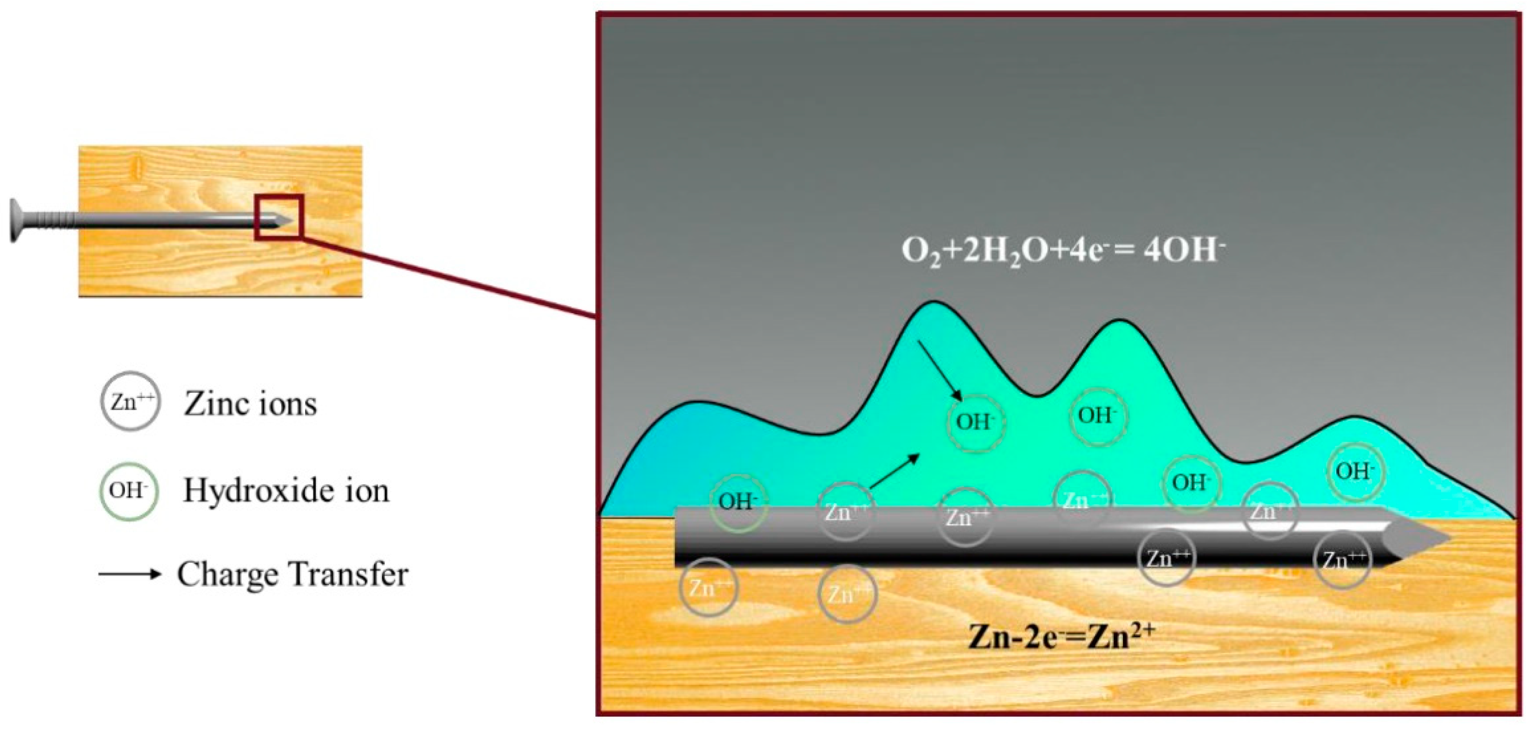
Varying salt concentrations significantly accelerate metal corrosion, with higher concentrations leading to increased corrosion rates. For example, a 5% salt solution can increase the corrosion rate by up to 30% compared to a 3% solution. This effect is compounded by dissolved oxygen content, which further exacerbates corrosion. Corrosion rates also exhibit regional variability due to differing natural environmental conditions, underscoring the necessity for localized, quantitative analyses.
(3)
The load-carrying capacity of metal connectors is affected by chemical interactions between the salt solution, wood, and galvanized nails. The formation of chelates due to these interactions can reduce the load-bearing capacity by up to 25%, significantly weakening the joints in the timber frame buildings. This reduction in capacity highlights the critical risk of corrosion and structural compromise in high-salt environments.
Therefore, when designing and constructing timber frame buildings, it is imperative to meticulously consider the use of wood-compatible preservation measures or alternate connecting elements. This ensures the sustainability and long-term stability of the structure. It is crucial to delve deeper into discussing the effectiveness of various wood preservation methods in mitigating the adverse effects of high-salt environments on wood structures. Additionally, exploring the performance and durability of different wood species under such conditions offers valuable insights for practitioners. Furthermore, a comprehensive analysis of the impact of alternative connecting elements on structural stability and longevity is necessary, taking into account factors such as material compatibility, corrosion resistance, and load-bearing capacity.
Future research directions could include the following:
  • Examining a wider range of nail types and coatings to determine the most effective materials for use in saline environments.
  • Investigating the long-term effects of saline exposure over multiple years to better understand the durability and reliability of nail connections in such conditions. Establish a model that can accurately predict corrosion failure.
  • Evaluating the effectiveness of various wood preservation methods in mitigating the adverse effects of high-salt environments.
  • Exploring the performance and durability of different wood species under such conditions.

Author Contributions

J.L. (Jia Lei): Writing—Original Draft, Methodology, Data Curation, Conceptualization. J.L. (Jingkang Lin): Experimental materials were provided. Z.C.: Writing—Review and Editing. S.J.: Writing—Review and Editing. Y.Z.: Investigation, Formal Analysis. Z.Q.: Super vision, Project Administration, Funding Acquisition. All authors have read and agreed to the published version of the manuscript.

Funding

This work was supported by the Fujian Provincial Department of Housing and Urban–Rural Development Science and Technology Plan Project (No.2023-K-14) and the Undergraduate Innovation Project of Nanjing Forestry University (No. 2023NFUSPITP0025). The authors would like to express their sincere thanks for this support.

Data Availability Statement

Data will be made available on request.

Conflicts of Interest

Author Jingkang Lin was employed by the company Fujian Provincial Institute of Architectural Design and Research Co., Ltd. The remaining authors declare that the research was conducted in the absence of any commercial or financial relationships that could be construed as a potential conflict of interest.

References

  1. Kirker, G.T.; Brischke, C.; Passarini, L.; Zelinka, S.L. Salt Damage in Wood: Controlled Laboratory Exposures and Mechanical Property Measurements. Wood Fiber Sci. 2020, 52, 44–52. [Google Scholar] [CrossRef]
  2. Slamová, K.; Glaser, R.; Schill, C.; Wiesmeier, S.; Köhl, M. Mapping Atmospheric Corrosion in Coastal Regions: Methods and Results. J. Phys. Conf. Ser. 2012, 2, 022003. [Google Scholar] [CrossRef]
  3. Crossman, M.; Simm, J.; Crossman, M. Manual on the Use of Timber in Coastal and River Engineering; Thomas Telford: London, UK, 2004. [Google Scholar]
  4. Prieto, A.J.; Silva, A. Service Life Prediction and Environmental Exposure Conditions of Timber Claddings in South Chile. Build. Res. Inf. 2020, 48, 191–206. [Google Scholar] [CrossRef]
  5. Treu, A.; Zimmer, K.; Brischke, C.; Larnøy, E.; Gobakken, L.R.; Aloui, F.; Cragg, S.M.; Flæte, P.-O.; Humar, M.; Westin, M.; et al. Durability and Protection of Timber Structures in Marine Environments in Europe: An Overview. BioResources 2019, 14, 10161–10184. [Google Scholar] [CrossRef]
  6. Skulteti, M.J.; Bender, D.A.; Winistorfer, S.G.; Pollock, D.G. Withdrawal Strength of Ring-Shank Nails Embedded in Southern Pine Lumber. Trans. ASAE 1997, 40, 451–456. [Google Scholar] [CrossRef]
  7. Fei, B.H. Nail Withdrawal Strength of Chinese Fir Plantation. Wood Process Mach. 2008, 5, 31–34. [Google Scholar]
  8. Wang, S.; Wang, F.; Kong, F.; Ma, P.; Chen, Z.; Que, Z. Influence of Repeated Wetting and Drying on Withdrawal Capacity of Wooden Nails and Metal Nails. Constr. Build. Mater. 2023, 409, 133991. [Google Scholar] [CrossRef]
  9. Teng, Q.; Que, Z.; Zeng, N. Effects of Angles on the Screw and Nail Withdrawal Strength in Dimension Lumber. Sci. Silvae Sin. 2020, 56, 154–161. [Google Scholar] [CrossRef]
  10. Zelinka, S.L.; Sichel, R.J.; Stone, D.S. Exposure Testing of Fasteners in Preservative Treated Wood: Gravimetric Corrosion Rates and Corrosion Product Analyses. Corros. Sci. 2010, 52, 3943–3948. [Google Scholar] [CrossRef]
  11. Yerman, L.; Ottenhaus, L.-M.; Montoya, C.; Morrell, J.J. Effect of Repeated Wetting and Drying on Withdrawal Capacity and Corrosion of Nails in Treated and Untreated Timber. Constr. Build. Mater. 2021, 284, 122878. [Google Scholar] [CrossRef]
  12. Que, Z.; Yang, L.; Wang, F.; Zhu, X.; Wang, Y.; Mori, T. Effects of Salinity on the Nail-Holding Power of Dimension Lumber Used in Light-Frame Wood Building. J. For. Res. 2015, 26, 765–770. [Google Scholar] [CrossRef]
  13. GB 50005—2017; Standard for Design of Timber Structures. China Architecture and Building Press: Beijing, China, 2018.
  14. GB/T 1927.4-2021; Test Methods for Physical and Mechanical Properties of Small Clear Wood Specimens—Part 4: Determination of Moisture Content. China Architecture and Building Press: Beijing, China, 2021.
  15. GB/T 1927.5-2021; Test Methods for Physical and Mechanical Properties of Small Clear Wood Specimens—Part 5: Determination of Density. China Architecture and Building Press: Beijing, China, 2021.
  16. GB/T 1927–2022; Test Methods for Physical and Mechanical Properties of Small Clear Wood Specimens, Part 21: Determination of Nail and Screw Holding Power. Chinese Standards Press: Beijing, China, 2022.
  17. ISO 9087:1998; Wood—Determination of Nail and Screw Holding Power Under Axial Load Application. International Organization for Standardization: Geneva, Switzerland, 1998.
  18. Tang, Y.J.; Meng, Q.; Ren, P. Spatial Distribution and Concentrations of Salt Fogs in a Coastal Urban Environment: A Case Study in Zhuhai City. Build. Environ. 2023, 234, 110156. [Google Scholar] [CrossRef]
  19. Celebi, G.; Kilic, M. Nail and Screw Withdrawal Strength of Laminated Veneer Lumber Made Up Hardwood and Softwood Layers. Constr. Build. Mater. 2007, 21, 894–900. [Google Scholar] [CrossRef]
  20. Wu, G.F.; Lang, Q.; Song, S.; Pu, J. Impregnation and Drying Schedule of Eucalyptus Wood. Adv. Mater. Sci. Eng. 2011, 71–78, 860–863. [Google Scholar] [CrossRef]
  21. Permeh, S.; Lau, K. Corrosion of Galvanized Steel in Alkaline Solution Associated with Sulfate and Chloride Ions. Constr. Build. Mater. 2023, 392, 131889. [Google Scholar] [CrossRef]
  22. Francis, R. Galvanic Corrosion. In Corrosion in Seawater Systems; Francis, R., Ed.; CRC Press: Boca Raton, FL, USA, 2019; pp. 109–126. [Google Scholar]
  23. Morcillo, M.; Diaz, I.; Cano, H.; Chico, B.; de la Fuente, D. Atmospheric Corrosion of Weathering Steels. Overview for Engineers. Part II: Testing, Inspection, Maintenance. Constr. Build. Mater. 2019, 222, 750–765. [Google Scholar] [CrossRef]
  24. Soufeiani, L.; Foliente, G.; Nguyen, K.T.Q.; San Nicolas, R. Corrosion Protection of Steel Elements in Facade Systems—A Review. J. Build. Eng. 2020, 32, 101759. [Google Scholar] [CrossRef]
  25. Zelinka, S.L.; Glass, S.V.; Boardman, C.R.; Derome, D. Comparison of the Corrosion of Fasteners Embedded in Wood Measured in Outdoor Exposure with the Predictions from a Combined Hygrothermal-Corrosion Model. Corros. Sci. 2016, 102, 178–185. [Google Scholar] [CrossRef]
  26. Yu, S.; Liu, Y.; Chen, Q.; Yu, X.; Hyun, G.; Wang, S.; Ye, Y.; Feng, J.; Chen, Z.; Jiang, F.; et al. Damage-Tolerant Wood Layers for Corrosion Protection of Metal Structures. Nano Lett. 2023, 24, 245–253. [Google Scholar] [CrossRef]
  27. Luszczki, G.E.; Clapp, J.D.; Davids, W.G.; Lopez-Anido, R. Withdrawal Capacity of Plain, Annular Shank, and Helical Shank Nail Fasteners in Spruce-Pine-Fir Lumber. For. Prod. J. 2013, 63, 213–220. [Google Scholar] [CrossRef]
  28. Ceylan, A.; Girgin, Z.C. Comparisons on Withdrawal Resistance of Resin and Phosphate Coated Annular Ring Nails in CLT Specimens. Constr. Build. Mater. 2020, 63, 213–220. [Google Scholar] [CrossRef]
  29. Brandner, R.; Ringhofer, A.; Grabner, M. Probabilistic Models for the Withdrawal Behavior of Single Self-Tapping Screws in the Narrow Face of Cross Laminated Timber (CLT). Eur. J. Wood Wood Prod. 2018, 76, 13–30. [Google Scholar] [CrossRef]
Figure 1. The main geometric features of the nails used.
Forests 15 01387 g001
Figure 2. Schematic diagram of nail-holding power specimens.
Forests 15 01387 g002
Figure 3. Salt treatment: (a) soaking (b) drying.
Forests 15 01387 g003
Figure 4. Universal test machine schematic set-up. (a) Diagram of the test assembly. (b) Examples of tests.
Forests 15 01387 g004
Figure 5. Examples of cracking in specimens subjected to repeated treatment (Salinity 3.5%, The fourth cycle).
Forests 15 01387 g005
Figure 6. Effect of increasing cycles and salinity on the untreated and treated samples was observed. (a) Examples of wood discoloration in three sections. (b) Cross-section of specimen at the end of the experiment.
Forests 15 01387 g006
Figure 7. Examples of load-displacement curves for nail withdrawal tests on cycle 4 and 4% salt solution.
Forests 15 01387 g007
Figure 8. The nail-holding power under different concentrations and test periods. (a) The radial section of the nail-holding power. (b) Tangential section. (c) Cross section.
Forests 15 01387 g008
Figure 9. Schematic diagram of corrosion mechanism of galvanized spiral nails.
Forests 15 01387 g009
Figure 10. The same cycle in different salinities of the nail-holding power.
Forests 15 01387 g010
Figure 11. Nail−holding power of the third period under different salinity conditions.
Forests 15 01387 g011
Table 1. Dimensions of nails (unit: mm).
TypeLS1S2S3DdP
Spiral nails3862753.53.31.5
Table 2. Steps taken during the experimental plan.
StepComments
1Cut timber specimensSee Figure 2 for size
2Determine the moisture content of each specimenUsing small samples. Oven-dry method
3Manually drive nails in the woodRefer to Table 1 for nail sizes and Figure 1 for nail geometry
4Perform the nail-holding power testsValues corresponding to Cycle 0
5Wet-dry cycle: soak samples in salt solution at ambient temperature for three daysSoak until the moisture content reaches 50%–60%, determined by gravimetry
6Wet-dry cycle: the sample is dried outdoors for two daysDry until the moisture content drops to 10%–20%, determined by gravimetry
7Perform the nail-holding power testsValues corresponding to Cycle 1
8Assess fastener conditionCheck the condition of the wood around the nails
Note: For values corresponding to Cycle n (n = 2, 3, 4, 5 and 6), steps 5 and 6 were repeated n times, then steps 7 to 8 were carried out.
Table 3. The proportion of simulated high-salt solution.
Salinity/%Crude Salt/KgDistilled Water/L
0.0%0.030.00
3.0%1.032.33
3.5%1.027.57
4.0%1.536.00
4.5%1.531.83
Table 4. Nail-holding power (N∙mm−1) after being treated in different cycle and concentrations.
Salinity
(%)
The First CycleThe Second CycleThe Third Cycle
Nail-Holding Power (N∙mm−1)Nail-Holding Power (N∙mm−1)Nail-Holding Power (N∙mm−1)
PS1PS2PS3PS1PS2PS3PS1PS2PS3
024.5221.3912.7321.6719.0712.3523.0425.5011.67
(3.19)(2.95)(3.46)(3.10)(2.61)(3.46)(3.32)(2.47)(2.49)
328.1317.619.9127.2029.1510.5317.8316.5011.74
(2.81)(3.03)(1.73)(2.92)(2.55)(3.18)(3.21)(2.85)(2.97)
3.533.2029.879.8634.2731.7119.3115.0016.0012.08
(3.07)(2.47)(3.32)(3.21)(2.43)(3.05)(3.45)(2.92)(2.81)
424.7823.349.5226.0721.0112.6714.3114.0211.18
(3.21)(3.18)(2.24)(2.47)(3.15)(2.86)(3.32)(3.07)(2.51)
4.530.2619.307.5727.4828.4015.0213.7813.6011.26
(3.36)(3.54)(2.45)(2.92)(2.43)(3.22)(3.51)(3.22)(2.86)
Salinity
(%)
The fourth cycleThe fifth cycleThe sixth cycle
Nail-holding power (N∙mm−1)Nail-holding power (N∙mm−1)Nail-holding power (N∙mm−1)
PS1PS2PS3PS1PS2PS3PS1PS2PS3
024.8926.1712.3022.5220.3911.7320.6719.8711.35
(2.14)(2.41)(2.83)(2.49)(1.92)(2.45)(2.37)(1.95)(2.45)
318.1118.2513.5317.1317.5113.4117.1016.1512.53
(2.92)(1.87)(2.47)(2.43)(2.68)(2.85)(2.74)(2.12)(3.02)
3.515.2715.7111.3114.2016.8710.8614.0715.719.31
(2.51)(2.21)(2.51)(2.51)(2.98)(2.51)(2.98)(2.51)(2.51)
415.0715.2311.2214.1715.7910.3013.6714.679.25
(2.85)(3.15)(3.03)(3.05)(2.66)(2.24)(2.85)(3.30)(2.28)
4.514.7814.8011.4813.3612.737.3711.4811.407.02
(2.55)(2.21)(2.72)(2.07)(3.39)(2.28)(2.55)(2.21)(1.84)
Note: The value of each row represents the average value of each group of specimens. The values in parentheses represent the standard deviation, and PS1 in the table represents the radial section of the nail-holding power. PS2 stands for tangential section. PS3 stands for cross section.
Table 5. Variance analysis and significance test of the effect of salinity and cycle on nail-holding power.
PropertiesFactorSum of SquaresDFF ValuePPartial η2
PS1Salinity264.23548.695<0.0010.225
Cycle4975.5785130.981<0.0010.845
Salinity × Cycle1709.9412011.253<0.0010.652
Error911.691120
PS2Salinity689.326424.787<0.0010.452
Cycle1863.134553.596<0.0010.691
Salinity × Cycle1600.0992011.507<0.0010.657
Error834.300120
PS3Salinity161.55946.774<0.0010.184
Cycle314.267510.542<0.0010.305
Salinity × Cycle463.273203.885<0.0010.393
Error715.496120
Note: Significance level α = 0.05.
Table 6. Pairwise Comparisons of Nail-Holding Power Across Different Cycles for Various Salinity Levels.
PropertiesSalinity(I) Cycle(J) CycleMean DifferenceP95% CI
Lower BoundUpper Bound
PS10.02.04.0−6.104 *0.010−11.325−0.883
3.04.0−6.150 *0.009−11.371−0.929
6.011.944 *0.0006.72317.165
4.06.011.238 *0.0006.01716.459
5.06.010.974 *0.0005.75316.195
3.01.03.0−11.944 *0.000−17.165−6.723
4.0−11.238 *0.000−16.459−6.017
5.0−10.974 *0.000−16.195−5.753
6.012.416 *0.0007.19517.637
2.03.012.328 *0.0007.10717.549
4.011.622 *0.0006.40116.843
5.011.358 *0.0006.13716.579
6.012.800 *0.0007.57918.021
3.51.03.019.494 *0.00014.27324.715
4.018.808 *0.00013.58724.029
5.020.006 *0.00014.78525.227
6.021.808 *0.00016.58727.029
2.03.017.392 *0.00012.17122.613
4.016.706 *0.00011.48521.927
5.017.904 *0.00012.68323.125
6.019.706 *0.00014.48524.927
4.01.02.09.156 *0.0003.93514.377
3.014.756 *0.0009.53519.977
4.018.594 *0.00013.37323.815
5.018.914 *0.00013.69324.135
6.019.286 *0.00014.06524.507
2.03.05.600 *0.0250.37910.821
4.09.438 *0.0004.21714.659
5.09.758 *0.0004.53714.979
6.010.130 *0.0004.90915.351
4.51.03.015.930 *0.00010.70921.151
4.016.986 *0.00011.76522.207
5.017.690 *0.00012.46922.911
6.017.692 *0.00012.47122.913
2.03.013.508 *0.0008.28718.729
4.014.564 *0.0009.34319.785
5.015.268 *0.00010.04720.489
6.015.270 *0.00010.04920.491
Note: Based on estimated marginal means. *. The mean difference is significant at the 0.05 level. Adjustment for multiple comparisons: Bonferroni.
Table 7. Pairwise Comparisons of Nail Holding Power Across Different Salinity Levels for Various Cycles.
PropertiesCycle(I) Salinity(J) SalinityMean DifferenceP95% Confidence Interval for Difference
Lower BoundUpper Bound
PS11.00.03.5−9.396 *0.000−14.381−4.411
4.0−9.396 *0.000−14.381−4.411
4.5−5.790 *0.012−10.775−0.805
3.03.5−5.492 *0.021−10.477−0.507
4.0−5.492 *0.021−10.477−0.507
2.00.03.0−8.240 *0.000−13.225−3.255
3.5−11.246 *0.000−16.231−6.261
4.5−7.320 *0.001−12.305−2.335
3.00.08.240 *0.0003.25513.225
3.54.07.054 *0.0012.06912.039
3.00.03.56.100 *0.0071.11511.085
4.56.142 *0.0061.15711.127
4.00.03.09.486 *0.0004.50114.471
3.511.564 *0.0006.57916.549
4.011.350 *0.0006.36516.335
4.513.348 *0.0008.36318.333
5.00.03.58.076 *0.0003.09113.061
4.06.984 *0.0011.99911.969
4.59.366 *0.0004.38114.351
6.00.03.05.826 *0.0110.84110.811
3.59.726 *0.0004.74114.711
4.07.204 *0.0012.21912.189
4.59.216 *0.0004.23114.201
Note: Based on estimated marginal means. *. The mean difference is significant at the 0.05 level. Adjustment for multiple comparisons: Bonferroni.
Disclaimer/Publisher’s Note: The statements, opinions and data contained in all publications are solely those of the individual author(s) and contributor(s) and not of MDPI and/or the editor(s). MDPI and/or the editor(s) disclaim responsibility for any injury to people or property resulting from any ideas, methods, instructions or products referred to in the content.

