Abstract
In this paper, we focus on the parking path planning and path tracking control under parallel parking conditions with automatic parking system as the research object. In order to solve the problem of discontinuity of curvature in the path planning of traditional arc-straight combined curve, a quintic polynomial is used to smooth the path. we design a path tracking controller based on the incremental model predictive control (MPC). The preview control based on pure tracking algorithm is used as the comparison algorithm for path tracking. The feasibility of the controller is verified by building a Simulink/CarSim co-simulation platform. In addition, the practicality of the parking controller is further verified by using the ROS intelligent car in the laboratory environment.
1. Introduction
With the improvement of living standards, the role of cars has gradually changed from a luxury to a necessity of people’s daily lives. Parking spaces are getting smaller and smaller, the parking environment is complex and changeable, the driver level is uneven, and other factors all affect the success rate of parking; a little carelessness may lead to the occurrence of parking accidents.
At present, the domestic and foreign researchers mainly adopt the following methods for automatic parking system research: (1) parking method based on intelligent control. Hanafy et al. used artificial fish swarm algorithm and bee swarm algorithm to optimize the parameters of the fuzzy controller, obtain the time required for parking, and optimize the performance of the parking controller [1]. Chengrui Zhang designed the control strategy of the automatic parking system based on the fuzzy control theory and verified the feasibility of the designed strategy through the Simulink/CarSim co-simulation and the vehicle controller built on dSPACE [2]. Demirli designed an Adaptive Neuro-Fuzzy Inference System. The vehicle does not need to know the desired polynomial path to track, but it will approximate such a way by knowing only the start configuration [3]. Huang proposed a model-free intelligent, self-organizing fuzzy controller for parking path tracking. This intelligent controller has a system-learning mechanism without expert knowledge or a trial-and-error process [4]. (2) parking method based on path planning and path tracking. Kim et al. proposed a Reeds-Shepp curve path planning that takes the minimum turning radius of the vehicle and the straight line from the starting point to the target point as the shortest path. Aiming at the problem that the path formula of the Reeds-Shepp curve is limited in the actual parking lot, the curve algorithm is modified, so as to realize the effective forward and backward automatic parking system [5]. Hao Ye designed a linear time-varying path tracking prediction through a series of transformations such as discretization and Taylor’s formula expansion [6].
MPC was proposed in the 1970s. It is an advanced control method that is usually used to control a process with constraints. It is a heuristic control algorithm applied in the industrial process and has rich theoretical and practical contents [7,8,9]. Model predictive controllers depend on models of the process, which are often linear models. There should be desirable properties of approximation accuracy, physical interpretation, suitability for control, and ease of development for a good model [10]. MPC is a typical approach in industrial advanced control. It has been widely used in various domains, such as supply chain management in semiconductor manufacturing [11], application to autoclave composite processing [12], energy efficiency control in buildings [13], integrated wastewater treatment systems [14], flight control [15], and magnetic spacecraft attitude control [16].
Compared with the parking system designed by intelligent algorithm, the parking system designed by path planning and path tracking has clear and simple design logic and can easily achieve global optimization. It is easy to integrate the pre-designed control strategy into the parking controller and facilitate the use of real cars. Therefore, it is the most studied automatic parking scheme at present. Hence, in this article, the parking path is planned based on the vehicle kinematics model and an automatic parking path tracking based on the incremental model predictive control (MPC). In order to improve the safety and reliability of the parking process, the article will analyze and study the path decision planning and path tracking control algorithms of the automatic parallel parking system.
2. Parking Path Planning
Parking path planning is essentially based on on-board sensors to obtain environmental information, combined with the kinematic constraints, vehicle parking environmental constraints, initial position of motor vehicles, and parking regulations. It is generated by a parking starting point into the parking space target preset position as the end point of the path curve, which is to meet the conditions of curvature, obstacle avoidance, and ease of tracking. Figure 1 is the basic structure of path planning in this paper.
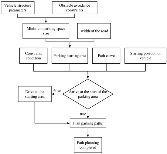
Figure 1.
Parking path planning structural schematic diagram.
2.1. Kinematic Model of Vehicle
The structural parameters of the vehicle, such as vehicle length, vehicle width, wheelbase, and front and rear suspension, have an important influence on the design of parking path planning and trajectory tracking controllers. In addition, the maximum steering wheel angle (the maximum steering wheel angle) and the maximum rotating speed of steering wheel Angle (the maximum rotating speed of steering wheel angle) also have a great relationship with the design of automatic parking system. The smaller the minimum turning radius of a vehicle, the smaller the required parking space size. This paper takes a certain model as the research object and simplifies the vehicle shape. Table 1 shows the vehicle structure parameters.

Table 1.
Vehicle structure parameters.
Because the parking speed is very low, there is no need to consider the vehicle’s handling, stability, and other dynamics issues. The tire side sliding is ignored, and the wheels only do rolling and steering [17]. As shown in Figure 2, the motion trajectory of the midpoint of the rear axle is used to represent the motion state of the vehicle. is used to represent the pose state of the vehicle at each moment. is used to represent the control quantity of the target vehicle to establish the kinematics model, and its kinematics equation is as follows [18]:
where, X and Y are the horizontal and vertical coordinates of the midpoint of the rear axle of the target vehicle (m); φ is the heading Angle of vehicle (°/s); δf is equivalent front wheel Angle ; l is wheelbase (m); v is rear axle midpoint velocity (km/h).
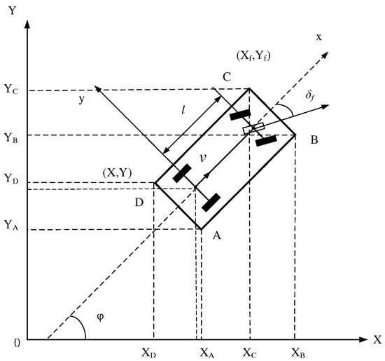
Figure 2.
Vehicle kinematics model.
2.2. Parking System Analysis
The speed of the vehicle is very low when parking. According to the above hypothesis, there is no wheel slip, so the speed at the center point of the rear axle in the direction of the rear axle is zero. Through analysis and calculation, the trajectory equation of the center point of the rear axle can be obtained:
Further observation of Equation (2) shows that:
According to Equation (3), when the equivalent front wheel rotation angle is fixed, the trajectory of the center point of the rear axle is only related to the wheelbase of the vehicle and has nothing to do with the reversing speed . The size of the reversing speed will not change the shape of the reversing trajectory. Given the front wheel rotation angle and speed, the reversing trajectory is strictly a circle [19]. According to the geometrical relation shown in Figure 2, the mathematical expression of the four vertex coordinates and the midpoint coordinates of the rear axle of the car body can be calculated.
Point A coordinates:
Point B coordinates:
Point C coordinates:
Point D coordinates:
As shown in Figure 3, we take the traditional arc-straight-arc path curve as an example to calculate the initial parking area that satisfies a series of constraints [20]. In order to reduce the length of parking space as much as possible and facilitate calculation, this paper sets the radius of two arcs equal to the minimum turning radius of the center of the rear axle of the vehicle, namely . Then, the driving track of P3P4 segment of the circular arc is the reverse process of P1P2 segment of the circular arc. After the positions of P3 and P4 are determined according to the constraint conditions, the coordinate of P1 position can be obtained only by adjusting the length of the straight line P2P3, and then the range of the starting point of parking can be calculated.
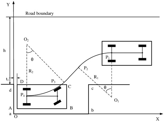
Figure 3.
Parallel parking start area analysis.
Through analysis and calculation, the lower limit value of P1 coordinate is P1min(,) = (8.076, 3.335). The upper limit value is P1max(,) = (10.981,4.588). The upper limit value of P2 coordinate is P2max(,) = (9.246,), and parking starting point area is as follows:
The starting point area of parking enclosed by Equations (8) and (9) is shown in the shaded part in Figure 4.
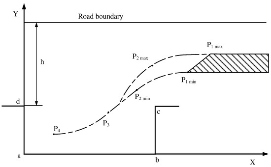
Figure 4.
Parking starting point area.
2.3. Parallel Parking Path Planning Based on Quintic Polynomial
For parallel parking path planning, the category of the fitting path curve needs to be determined first. In this paper, we hope that the curvature of the planned path is continuous, which requires the path to be second-order continuous. The output of the parking system is the steering angle of the front wheels, and the steering angle is controlled by the power-assisted motor. Due to the motor steering performance constraints and the inertial characteristics of the steering system, the steering angle of the wheels cannot change suddenly, which requires the planned path to be three-order continuous. Therefore, if a polynomial is used to fit the parking path, the curve is at least a fourth-degree polynomial.
The following requirements must be met when parking: the curvature of the path curve is continuous to prevent the vehicle from turning in place; the curvature of the starting and ending points of the path curve is zero to ensure that the vehicle body attitude is parallel to the parking space at these two points; the steering wheel at the end of parking is in the state of returning to normal. It can be seen from Table 2 that the curve that can meet these requirements and has a simple structure of the path curve and a small amount of calculation is a fifth-order polynomial curve.
Table 2.
Comparison of advantages and disadvantages of different path curves.
In this paper, combining the path planning constraints analyzed in the previous section and comparing the advantages and disadvantages of various path curves, a quintic polynomial is selected for path smoothing processing, and its expression is shown in Equation (10) [21].
where a0∼a5 are the coefficients of a quintic polynomial, and changing the coefficients can change the shape of the polynomial.
Substituting vehicle position constraints at the starting and ending points, heading angle constraints, steering stability constraints, and obstacle avoidance constraints into Equation (10), the unique path equation can be determined, which is the desired parallel parking path curve. The simulation program was written in MATLAB, and the simulation results are shown in Figure 5.
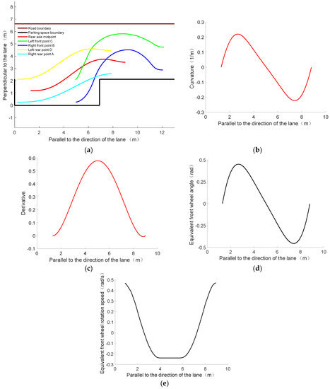
Figure 5.
Parallel parking path planning simulation results. (a) Vehicle rear axle midpoint trajectory. (b) The curvature of the path curve. (c) The derivative of the path curve. (d) Equivalent front wheel angle. (e) Equivalent front wheel rotation speed.
As can be seen from Figure 5, the planned path curve is a continuous curve connecting the starting and ending points of parking. The four vertices of the target vehicle body contour, A, B, C, and D, all meet the requirements of obstacle avoidance and reach the termination point without collision from their respective starting points. In other words, the parallel parking path curve using quintic polynomial programming can meet the constraint requirements. The curvature of the path curve meets the requirement that the curvature is less than the maximum curvature determined by the vehicle structure parameters, and the curvature is continuous without abrupt change during the whole parking process. Derivatives at the starting point and the ending point are approximately equal to zero, which meets the requirement that the vehicle body attitude is parallel to the horizontal direction of the parking space. In the whole parking process, the equivalent front wheel keeps rotating. The angle and speed are constantly changing to meet the constraints. Therefore, the parking path curve programmed by quintic polynomial has good tracking performance, and can satisfy the vehicle environment constraints, pose constraints, and vehicle kinematics constraints.
3. Motion Control of Path Tracking Based on MPC
In this section, the model predictive control algorithm is selected to track the parking path designed in the previous section [22].
3.1. Design of Parking Path Following Controller
In order to realize path tracking motion control effectively, a path tracking controller based on incremental model predictive control (MPC) is designed in this paper, and the preview control based on pure tracking algorithm is used as the comparison algorithm for path tracking. The kinematics model of Equation (1) is discretized, and and , then the system can be regarded as a control system with an input of and state quantity of . For a given reference trajectory, Taylor’s formula is used to expand, and higher-order terms are ignored, and the following can be obtained:
By making a difference between Equation (11) and the general form, a linearized parking vehicle error model can be obtained, which is further discretized and used as the input of MPC. The formula after discretization is as follows:
where, ; ; is the sampling time.
Considering the rapidity and stability of path tracking when parking, the deviation of system state quantity and control quantity need to be reflected in the objective function, so the objective function is designed as follows:
where represents the weight coefficient; denotes relaxation factor; represents the prediction time domain; represents the control time domain; and are weight matrices. The first item on the right side of the equal sign reflects the tracking ability of the controlled system to the reference path, and the last item reflects the change of the constraint control quantity of the controlled system.
In the control process of path tracking of parking system, some constraints need to be considered, which are mainly the limit control quantity constraint and control increment constraint, such as the constraint of front wheel rotation angle. The constraint expression of parking system control quantity is:
The corresponding system control increment constraint expression is as follows:
3.2. Mulation and Result Analysis of Parallel Parking
The quintic polynomial path curve planned in the path planning part was taken as the reference target curve, and the model predictive control algorithm was used to track the curve, and the comparison with the preview control algorithm was made. Figure 6 shows the parking scene in the CarSim software in the joint simulation test of parallel parking conditions.
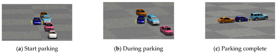
Figure 6.
CarSim parallel parking scene.
As can be seen from the above figure, the blue vehicle successfully finished parking in the co-simulation experiment. In MPC controller, parameters such as prediction time domain, control time domain, and relaxation factor are important parameters in controller design. We comprehensively consider the calculation time and calculation ability of the controller. Through literature review and actual testing, the basic parameters of the MPC controller designed in this paper are shown in Table 3:
Table 3.
MPC controller basic parameters.
The simulation results of parallel parking are shown in Figure 7:
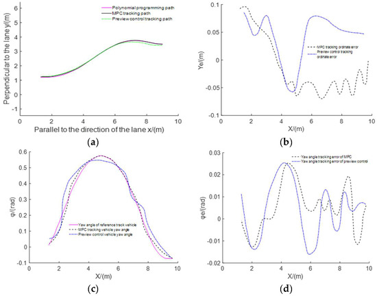
Figure 7.
Parallel parking path tracking simulation results. (a) Path tracking. (b) Ordinate tracking error curve. (c) Variation of yaw angle of vehicle. (d) Tracking error of vehicle yaw angle.
As can be seen from Figure 7a, the target vehicle can track the target path well under the control of both the MPC algorithm and the preview control algorithm, and the MPC algorithm has a better tracking effect than the preview control algorithm. In the process of vehicle tracking the desired path controlled by the two algorithms, there is no collision between the vehicle and the vehicle with obstacles before and after the target parking space and the obstacle avoidance requirements are met simultaneously. As can be seen from Figure 7b, the maximum ordinate error of path tracking based on MPC algorithm is 0.09638 m, while that based on preview control algorithm is 0.08602 m. Although the maximum ordinate error based on MPC is greater than that based on preview control, the overall error curve shows that the change of ordinate error based on MPC is smoother than that based on preview control. As can be seen from Figure 7c, at the end point of parking, the yaw angle of the vehicle tracked by the two control algorithms approaches 0, which meets the vehicle attitude requirements at the end point of parking. From the whole curve, the degree of fit between vehicle yaw angle and yaw angle of the desired path based on MPC tracking is higher than that based on preview control. As can be seen from Figure 7d, the maximum yaw error based on MPC is 0.02527 rad, and the yaw error at the parking termination point is −0.0013 rad, so the yaw tracking accuracy is high. The maximum yaw error based on the preview control is 0.026 rad, and the yaw error at the end point of parking is 0.0113 rad. The yaw tracking accuracy is less than that of the model predictive control. As can be seen from Table 4, the absolute value of ordinate error based on MPC is 0.018 m, while that based on preview controller is 0.039 m. And the average of yaw error based on MPC is less than that based on preview controller. To sum up, the path tracking algorithm designed by model predictive control is better than the path tracking algorithm designed by pure tracking algorithm.
Table 4.
Parking position error.
4. Parking Experiment of Intelligent Car
In order to verify the actual control effect of the control model and directly observe the test results, this paper carried out parallel parking experiments based on the industrial computer (Mini Intel i3) and the ROS intelligent car. Since the MPC algorithm is based on Simulink and cannot be used directly for the car, the MPC algorithm was rewritten in C++ and implemented on an industrial computer to support the following experiments. Table 5 shows the basic parameters of the smart car [23].
Table 5.
Basic parameters of intelligent car.
Firstly, the path tracking control algorithm based on MPC built by Simulink is duplicated in IPC by C++ language. Then, the serial port function of the ROS system is used to transfer the calculated expected angle and speed from the IPC to the control module with STM32F103RCT6 as the central chip. Finally, the control module transmits the control signal to the driving motor and steering gear, so as to control the transverse and longitudinal motion of the car. The basic structure of the intelligent car parking test platform built in this paper is shown in Figure 8.
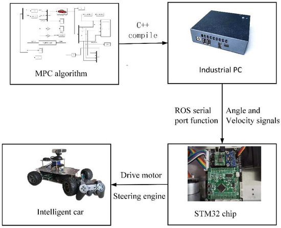
Figure 8.
Basic structure of intelligent car parking experiment.
Combined with the structural parameters of the intelligent car and according to the method of calculating the minimum parking size in the previous section, the minimum parallel parking size is determined to be 84 cm × 35 cm and the lane width to be 45 cm. After several experiments, the successful experimental results were recorded, as shown in Figure 9. It can be seen from the figure that the designed path tracking controller based on MPC can successfully control the car model parking and warehousing, and the car does not collide with the lane line and parking space line in the parking process, which meets the requirements of obstacle avoidance.
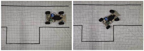
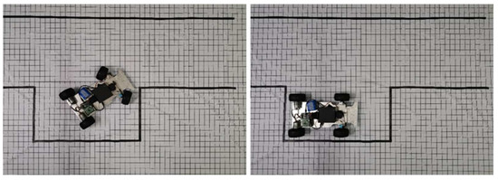
Figure 9.
Parallel parking car experiment.
5. Conclusions
This paper focuses on parallel parking path planning and tracking control. Firstly, a vehicle kinematic model is built to solve for the parking start point region, and path planning is performed by using the quintic polynomial. Then, we designed a path tracking controller based on incremental model predictive control (MPC). And the preview control based on pure tracking algorithm is used as the comparison algorithm for path tracking. The simulation results show that the designed path tracking controller can better control the vehicle tracking the desired path. Finally, we use the ROS smart car in a laboratory environment to verify the actual control effect of the control model and directly observe the test results.
6. Future Research Directions
The above experimental results verify the feasibility of the parking system, and the future research directions are as follows.
- Regarding parking conditions, this article only studies parallel parking conditions. For vertical parking conditions and parking with irregular parking spaces, further research is needed.
- Regarding the experiment, due to the lack of conditions, this article only uses the smart car to carry out the parking experiment. In the future, the designed controller needs to be verified on the actual vehicle.
- Regarding the development of automatic parking technology, automatic valet parking technology is an inevitable trend in the development of automatic parking technology in the future.
Author Contributions
Conceptualization, B.Z.; methodology, Z.L.; software, Y.N.; validation, Y.L. and Y.N.; formal analysis, Z.L.; investigation, Y.N.; resources, B.Z.; data curation, B.Z.; writing—original draft preparation, Z.L.; writing—review and editing, Z.L.; visualization, Y.N.; supervision, B.Z.; project administration, B.Z.; funding acquisition, B.Z. All authors have read and agreed to the published version of the manuscript.
Funding
This work was supported by Anhui provincial central committee guides local science and technology development project (Grant No. 202007d06020018) and the Fundamental Research Funds for the Central Universities of China (Grant No. PA2021GDSK0075).
Conflicts of Interest
The authors declare no conflict of interest.
References
- Hanafy, M.; Gomaa, M.M.; Taher, M.; Wahba, A.M. Development of a technology for car’s auto-parking using swarm search-based fuzzy control system. Int. J. Model. Identif. Control 2012, 17, 85. [Google Scholar] [CrossRef]
- Zhang, C.R. Research on Automatic Parking Route Decision Planning and Vehicle Control Algorithm; North University of China: Taiyuan, China, 2019. [Google Scholar]
- Demirli, K.; Khoshnejad, M. Autonomous parallel parking of a car-like mobile robot by a neuro-fuzzy sensor-based controller. Fuzzy Sets Syst. 2009, 160, 2876–2891. [Google Scholar] [CrossRef]
- Huang, S.-J.; Lin, G.-Y. Parallel auto-parking of a model vehicle using a self-organizing fuzzy controller. Proc. Inst. Mech. Eng. Part D J. Automob. Eng. 2010, 224, 997–1012. [Google Scholar] [CrossRef]
- Kim, J.M.; Lim, K.I.; Kim, J.H. Auto parking path planning system using modified reeds-shepp curve algorithm. In Proceedings of the 2014 11th International Conference on Ubiquitous Robots and Ambient Intelligence (URAI), Kuala Lumpur, Malaysia, 12–15 November 2014; pp. 311–315. [Google Scholar]
- Ye, H.; Jiang, H.; Ma, S.; Tang, B.; Wahab, L. Linear model predictive control of automatic parking path tracking with soft constraints. Int. J. Adv. Robot. Syst. 2019, 16, 1729881419852201. [Google Scholar] [CrossRef] [Green Version]
- Qin, S.; Badgwell, T.A. A survey of industrial model predictive control technology. Control Eng. Pract. 2003, 11, 733–764. [Google Scholar] [CrossRef]
- Mayne, D.Q.; Rawlings, J.B.; Rao, C.V. Constrained model predictive control: Stability and optimality. Automatica 2000, 36, 789–814. [Google Scholar] [CrossRef]
- Morari, M.; Barić, M. Recent developments in the control of constrained hybrid systems. Comput. Chem. Eng. 2006, 30, 1619–1631. [Google Scholar] [CrossRef]
- Pearson, R. Selecting nonlinear model structures for computer control. J. Process. Control 2003, 13, 1–26. [Google Scholar] [CrossRef]
- Wang, W.; Rivera, D.E.; Kempf, K.G. Model predictive control strategies for supply chain management in semiconductor manufacturing. Int. J. Prod. Econ. 2007, 107, 56–77. [Google Scholar] [CrossRef]
- Dufour, P.; Michaud, D.J.; Touré, Y. A partial differential equation model predictive control strategy: Application to autoclave composite processing. Comput. Chem. Eng. 2004, 28, 545–556. [Google Scholar] [CrossRef] [Green Version]
- Salsbury, T.; Mhaskar, P.; Qin, S.J. Predictive control methods to improve energy efficiency and reduce demand in buildings. Comput. Chem. Eng. 2013, 51, 77–85. [Google Scholar] [CrossRef]
- Brdys, M.; Grochowski, M.; Gminski, T.; Konarczak, K.; Drewa, M. Hierarchical predictive control of integrated wastewater treatment systems. Control Eng. Pract. 2008, 16, 751–767. [Google Scholar] [CrossRef]
- Keviczky, T.; Balas, G.J. Receding horizon control of an F-16 aircraft: A comparative study. Control Eng. Pract. 2006, 14, 1023–1033. [Google Scholar] [CrossRef]
- Silani, E.; Lovera, M. Magnetic spacecraft attitude control: A survey and some new results. Control Eng. Pract. 2005, 13, 357–371. [Google Scholar] [CrossRef]
- Jiang, M.G.; Lu, B. Ackerman principle and rectangular steering trapezoid design. Automob. Technol. 1994, 5, 16–19. [Google Scholar]
- Gong, J.W.; Liu, K.; Qi, J.Y. Model Predictive Control for Self-Driving Vehicles; Beijing Institute of Technology: Beijing, China, 2020; pp. 82–84. [Google Scholar]
- He, P. Research on Path Planning and Tracking Control of Parallel Parking; Chongqing University of Technology: Chongqing, China, 2020. [Google Scholar]
- Wu, Z.W. Path Planning and Simulation Analysis of Automatic Parking System for Passenger Car; South China University of Technology: Guangzhou, China, 2018. [Google Scholar]
- Li, T. Path Planning and Tracking of Automatic Parking System; Harbin Institute of Technology: Harbin, China, 2017. [Google Scholar]
- Yang, S.B.; Liu, H.; Jiang, Z.L. Automatic parking control method based on MPC. J. Instrum. Autom. Syst. 2019, 34, 20–23. [Google Scholar]
- Guo, Y.T. Research on Path Planning and Control System for Automatic Parallel Parking; Lanzhou Jiaotong University: Lanzhou, China, 2020. [Google Scholar]
Publisher’s Note: MDPI stays neutral with regard to jurisdictional claims in published maps and institutional affiliations. |
© 2022 by the authors. Licensee MDPI, Basel, Switzerland. This article is an open access article distributed under the terms and conditions of the Creative Commons Attribution (CC BY) license (https://creativecommons.org/licenses/by/4.0/).